Embed Size (px)
Citation preview

Energy Storage Cells Test Solution13 FEBRUARY 2019ANDREA VINCI – EMEA AUTOMOTIVE AND POWER BDM

13 FEBRUARY 2019 2
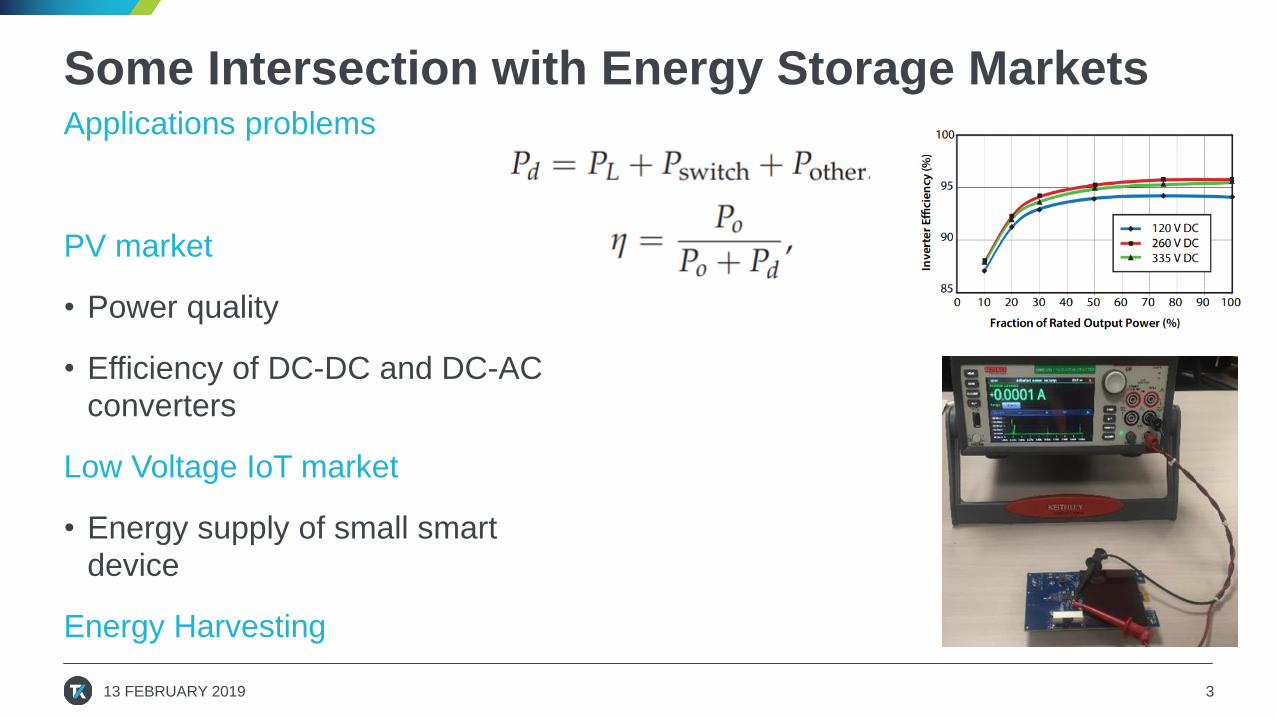
Some Intersection with Energy Storage MarketsApplications problems
PV market
• Power quality
• Efficiency of DC-DC and DC-AC converters
Low Voltage IoT market
• Energy supply of small smart device
Energy Harvesting
13 FEBRUARY 2019 3

What we may target (to be)Fast growing markets
• Electro-mobility
• Back-up power / renewables grid integration
What is the problem you are trying to solve?
• Requirements?
• Test problems?
• Custom Specific Needs?
• Software integration?
13 FEBRUARY 2019 4

Example of system we designed for IoT
13 FEBRUARY 2019 5
Higher Voltages
Smaller Size
More Energy per size
Improve Li-Ion
Electrodes -> Cathode materials
Membrane/Liquids
Smartphones
Electric Vehicles
Renewable Energies
Cost
Efficiency
Size
Lifetime
Safety
DC voltage ranges 40/60V
DC current ranges 100’s/1000’sA
IoT space
Integration in IoT for Vehicles
Vehicle trackers GPS
(3.7V backup, battery charging ICs)
Power Backup
(4.2V cell/1.5A, 2.5A output current)
Trends
Research
Demand markets
Metrics
Ranges

Batteries: Characteristics and Suitability• Composition of a
solution system kit:
• Power supply (AC/DC, DC/AC)
• Electronic load
• Voltmeter/ammeter (digitizer, datalogger)
• Thermal chamber
• Switches for series tests
• Control software
13 FEBRUARY 2019 6
Lithium Ion
Batteries
Consumer Electronics,
Electric mobility,
Energy Storage
Applications
Short Bursts of high current
Low current for long periods
…
Requirements
High
Energy
High Power
Density
To evaluate Battery Characteristics
and Suitability per Application you
need to check:
- Energy/Power (Ragone plot)
- Cell Impedance vs Temperature
- Cell Impedance vs Load
- Charge/Discharge Characteristics

How to test battery cell
• Short term performance◦ Battery function test: charge/discharge/protection
◦ Battery capacity
◦ Battery impedance (AC impedance)
• Long term performance◦ Aging performance
◦ Self-discharge
◦ Battery cell uniformity
• Research needs vs Industry needs
13 FEBRUARY 2019 7
CHARACTERIZE BATTERY CELL PERFORMANCE

Keithley in Research

Predict battery life by Columbic Efficiency
13 FEBRUARY 2019 9
• CE = Qd/Qc (discharge capacity/charge capacity)
◦ If CE = 1,battery has eternal life
◦ For real battery CE < 1,but very close
◦ CE is an constant throughout battery life
◦ CE could be used to predict battery long
term performance
Traditional battery tester could not be
used to measure CE because of the
accuracy
If CE = 0.9998, 1000 cycles lead to 81.87%
capacity left
Pioneering Li-Ion capacity test

Bring solutions to Industry

What is a Keithley SMU?
13 FEBRUARY 2019 11

What is Keithley TSP infrastructure?• Embedded Test Script Processor turns an instrument into a Smart Instrument
• Flexibility of Automated Test Programmer
• Much less GPIB transactions when a test sequence is executed rather than common SCPI command execution approach
13 FEBRUARY 2019 12

Program resides completely in the instrument
13 FEBRUARY 2019 13

Modeling the battery: cycle tests example• Use a Keithley 2461 SourceMeter® to simulate a battery.
• Get a battery model (with 101 points) generated by a separate TSP script
• Open circuit voltage and internal resistance as a function of the battery's state of charge
13 FEBRUARY 2019 14

Technical Background
13 FEBRUARY 2019 15
• The battery model used to create the simulation includes:◦ The battery’s capacity, in Amp-Hours
◦ The State of Charge (SoC) from 0 to 100%
◦ The Open Circuit Voltage at each SoC, in Volts
◦ The Internal Series Resistance at each SoC, in Ohms
• The Model 2461 measures current at 1MSample/sec and outputs voltage according to the formula:
• The voltage output has a response time of ~200µs ◦ i.e. it takes 200µs for Voutput to change after the current through the SMU changes

Technical Background• The simulation calculates the Amp-Hours output by/sunk by the SMU using the
trapezoidal integration method from the measured current and the SMU’s internal clock.◦ The simulation can handle both charging and discharging of the model
symmetrically
• Voc, ESR, SoC, and Capacity are interpolated (linearly) between the 101 points of the model
• This specific SMU has a current limit of 7A and an output limit of 7V. These limits may be reduced in the script if these high levels are not needed to increase responsiveness at lower current levels.
13 FEBRUARY 2019 16

Connections to your Device
13 FEBRUARY 2019 17
• The script requires a 4 wire connection to your device, leaving the sense leads disconnected may cause erratic behavior and damage to your device.
• Force Hi/Sense Hi should be connected to the device terminal expecting a positive voltage◦ Likewise, Force Lo/Sense Lo should be
connected to the device terminal expecting a
battery’s negative terminal.
• For highly sensitive devices, it is recommended to only make connections after the simulation starts.

Ways to Run the Script
13 FEBRUARY 2019 18
• The script can be loaded and run either from the front panel of the instrument or from an external computer using Keithley’s Test Script Builder (TSB) application.
13 FEBRUARY 2019 18
Script name
model name
Measured current
Open Circuit
Voltage
State of Charge (%)Internal Series Resistance (Ohms)
Terminal/Load Voltage
being output

Script
13 FEBRUARY 2019 19

Success cases in low power energy storage• SMU as constant current Load
13 FEBRUARY 2019 20

Discharge and recharge
13 FEBRUARY 2019 21

Example: battery self discharge
• Solution: Source very accurate/sable voltage and measure uA level current
13 FEBRUARY 2019 22
HOW TO AVOID WAITING FOR LONG TIME?
Self discharging
current
Compensation current
from SMU
Output
Voltage
Stable

Focus on Automotive• Characterizing the profile and the behavior of real rechargeable batteries
13 FEBRUARY 2019 23
Lithium Ion
Batteries
BMS
Battery Health
SOH
SOE
SOP
SOCImprove accuracy of SoC for
Lithium Ion Battery for EV
Mathematical Parameter
Estimation methods
Battery flowing
Integrators
Gauges
Available capacity
Value
Voltage, Current,
Temperature…

Example: Weld resistance test - EV batteries• Problem: Design a test bench for multiple
batteries weld resistance characterization
• Combine 7.5 digit DMM accuracy with switch capabilities and 4 wires measurements on several independent channels
• Find the right compromise between test time and accuracy to stay within single digit micro-ohms of noise) and stable reading
• Apply TSP-Link technology for multiple instruments master-slave test configuration and intergrate into LabView customer test environment
13 FEBRUARY 2019 24

Example: EV batteries production• China – Prismatic Cell batteries
• Insulator (separator) quality test
• Test Method : Apply HV (500V) to charge step by step, measure open circuit voltage (floating voltage) between pulses
• If drop is significant -> Issues with the separator
• Solution: SMU as Current source mode (20mA - 500V), switch to uArange quickly (0A, no leakage) -> measure voltage drop
13 FEBRUARY 2019 25

Battery Short Check Test 500V with 20mA
13 FEBRUARY 2019 26
Voltage waveform
w/o Battery
Voltage waveform
with Battery
0 V
0 V
500V
500V
Output On -> (20mA with 500V limit -> 0A with 500V) X 3 times -> Output Off(Discharge)
Measure Point at charging incomplete
V < 500V, I = 20mA(Imax) Low Resistance < 25k ohm
Measure Point at charging complete
V = 500V, I <10uA
Low Resistance > 100M ohm
V Measure Point
after charging
incomplete
Check self-
discharge