Embed Size (px)
DESCRIPTION
pump control & energy saving
Citation preview

Research Article
Advances in Mechanical Engineering2015, Vol. 7(7) 1–12� The Author(s) 2015DOI: 10.1177/1687814015589491aime.sagepub.com
Energy-saving control model ofinverter for centrifugal pump systems
Yin Luo, Shouqi Yuan, Hui Sun and Yihang Guo
AbstractThe inverter control strategy is the key to pump energy-saving operation and should be established based on the currentsystem configurations and system requirements, which is not the case in practice. As a result, the characteristics ofpump system requirements and a combination pump with inverter were studied, and the mathematical models wereestablished. A new model for an optimal inverter control strategy based on the current system configurations and sys-tem requirements was then established, and a method combining golden section search and genetic algorithm was for-mulated to solve this optimal model. This model sets up an optimal inverter control strategy to increase the efficiency ofpump operation following a process line near the minimum requirements to improve operation conditions. The imple-mentation difficulty of the control law was also reduced. Finally, the optimized model was applied to an industrial circu-lating pump system, and the result showed that the model can not only determine the optimal inverter control strategybut also evaluate the current operation situation of the pump configuration and determine the energy-saving potentialfor the current configuration, which can aid in the subsequent energy-saving reconstruction.
KeywordsEnergy-saving technology, inverter control strategy, variable pressure water supply, pump system characteristics
Date received: 21 November 2014; accepted: 1 March 2015
Academic Editor: Duc T Pham
Introduction
Pumps are widely used in industrial and service sectorapplications. Pumps consume approximately 10%–40% of electricity in these sectors.1,2 Pumping systemsare found to have a significant potential for energy effi-ciency improvements; using inverters in pumping appli-cations, variable speed pumping has been shown to beeffective in reducing total pumping costs, particularlyin systems that require a wide range.3–8
Despite being capable of adjusting the rotationspeed of the pump, an inverter cannot achieve energysavings directly. Energy saving can only be achievedthrough the optimal operation control strategy.5,6,9,10
Energy-saving efforts are affected by the optimizationdegree of the control strategy and the equipment con-figuration.9–11 As a result, the pump system shouldpossess an established inverter control law for energy-saving operations.
The variable pressure control law12–15 which fol-lowed the system characteristics could achieve the mini-mum supply for system requirements without throttleloss. However, the present pump configuration tends topromote the practice of sizing pumps conservatively toensure safety margins for the process, which couldcause the pump to operate under low efficiency. Thispractice results in low operating efficiency and highmaintenance costs with high noise. Second, due to thehigh price of the inverter, not all pumps are equipped
Research Center of Fluid Machinery Engineering and Technology, Jiangsu
University, Zhenjiang, China
Corresponding author:
Yin Luo, Research Center of Fluid Machinery Engineering and Technology,
Jiangsu University, Zhenjiang 212013, China.
Email: [email protected]
Creative Commons CC-BY: This article is distributed under the terms of the Creative Commons Attribution 3.0 License
(http://www.creativecommons.org/licenses/by/3.0/) which permits any use, reproduction and distribution of the work without
further permission provided the original work is attributed as specified on the SAGE and Open Access pages (http://www.uk.sagepub.com/aboutus/
openaccess.htm).
by guest on March 11, 2016ade.sagepub.comDownloaded from

with this device, and thus, the adjustment capability ofa pump system may be insufficient to enable the pumpto operate within the minimum requirements.
The constant pressure control law which keeps thepressure of pump outlet constant through the inverter isthe most common control law for pump systems. Thisapproach is easy to implement with closed-loop control.However, the constant pressure mode would cause pres-sure loss which means energy wastage when operatingunder small flow requirement, and the pump efficiencyis still not considered in actual operation.
Thus, the inverter control strategy should be estab-lished based on the current pump system configura-tions to achieve a supply that is close to minimumsystem requirements to save energy, as well as to enablethe pump to operate in an efficient operation area con-sidering the pump configuration with less switching fre-quency to prevent difficulty in implementation.However, there are few studies about that, especiallylack of the establish methods of the inverter controlstrategy.
In this work, a new model was established to achievean optimal inverter control strategy based on the cur-rent system configurations and system requirements.This optimal inverter control strategy enables pumpoperation in an efficient area following a process linenear the minimum requirements threshold to improveoperation conditions. The difficulty of implementingthe control law was also reduced.
Mathematical model of the efficientoperation area for pump group
A pump should be operated predominantly close to thebest efficiency point in the ‘‘preferred operation range.’’This mode of operation facilitates the lowest energy
and maintenance cost and reduces the risk of systemproblems because of hydraulic excitation forces andcavitation risk, as shown in Figure 1. Rules are thusneeded to define the allowable ranges and modes ofoperation to reduce the risk of damage and excessivewear.
Single-pump model
The range of the preferred continuous operation can bedefined according to some criteria; for instance, basedon the requirement that the efficiency must not fallbelow 80%–85% of the maximum efficiency of thepump in question. The allowable ranges can be definedby the efficiency must not fall below 70% of the maxi-mum efficiency.
Considering the general centrifugal pump, the Q–Hcharacteristics can be expressed as follows
H =Hx � SQ2 ð1Þ
Thus, the preferred operation range can also beexpressed as a curve section
H =Hx � SQ2 Q 2 ½QA,QB� ð2Þ
In this interval, with the head He, the flow range canbe recorded as
Qc(He)=
ffiffiffiffiffiffiffiffiffiffiffiHx�He
Sx
qHe 2 ½HA,HB�
0 He 62 (HA,HB)
(ð3Þ
With the flow Qe, the head range can be recorded as
Hc(Qe)=HX � SQ2
e Qe 2 ½QA,QB�HA
QAQ2
e Qe QA
�
Hea
d
% Flow
High tempertaure
rise
Low flow cavitation
Lower bearing & seal life
Suction recirculation
Lower inpeller lifeDischarge
Recirculation
Lower bearing & seal life
Cavitaion
80% 110%
Best Efficiency Point
Figure 1. Adverse effects of operating away from the BEP.
2 Advances in Mechanical Engineering
by guest on March 11, 2016ade.sagepub.comDownloaded from

When the pump is operated by an inverter, the rangeof speed regulation should be constrained. With anexcessive speed range, operation efficiency and reliabil-ity will decrease. Thus, considering the factors of oper-ation, the speed regulation range is constrained. Thepreferred operation range can be expressed as shown inFigure 2.
According to the affinity law in pump theory, l1 andl2 are set as similar lines in Figure 2. A, B, C, and D arethe boundaries of the operation zone, and l1 and l2 canbe expressed as
Hl1 =HA
QA
Q2l1, Hl2 =
HB
QB
Q2l2 ð4Þ
When the head He is needed for this water supplysystem, the boundary can change as
Qmin =QA
ffiffiffiffiffiHe
HA
qHe � HC
Qc He\HC
(ð5Þ
Qmax=QB
ffiffiffiffiffiHe
HA
qHe\HB
QB He � HB
(ð6Þ
When Qe is needed for this water supply system, theboundary can change as
Hmin =k2
minHX � SQ2e Qe\QD
HB
QBQ2
e Q � QD
�ð7Þ
Hmax =HX � SQ2
e Qe � QAHA
QAQ2
e Q\QA
�ð8Þ
Parallel operation pump group model
The advantages of multiple pump parallel combinationsare flexibility, redundancy, and the capability to meetchanging flow needs efficiently in systems. In particular,adjustable speed drive tends to be more efficient
solutions to variable demand requirements. As a result,the configuration equipped with an inverter is commonin engineering practice.
The operation point of each pump is derived fromthe intersection of the system characteristic with thecombined characteristics of all pumps in operation. Inparallel operation, each unit has to pump against thesame pressure difference imposed by the system. Thus,the combined characteristic of the pumps is obtainedby adding the flow rates of all operating pumps at con-stant head. This method can also be used for the opera-tion area by adding each single-pump operation area ina head, as shown in Figure 3.The mathematical model can be shown as follows:
When the headHe is needed for the water supply sys-tem, the boundary can be changed according to equa-tions (5) and (6)
QZ=
Xx
i= 1
wi � QCik(He)+Xn
i= x
wi � QVikmin(He),
"
Xn
i= 1
wiQCik(He)+Xn
i= x
wi � QVikmax(He)
# ð9Þ
where n is the number of pumps, x expresses the con-stant speed operation pump, i denotes the ith pump, kis the kth type of pump, and wi is the switch vector. Inthe configuration of the ith pump selection, if the pumpis in operation, we use 1; otherwise, the value is 0.
Mathematical model of the operationdemand area for a pump system withinverter
A pump system with inverter configuration has strongregulating capability. With increasing speed of the reg-ulating device, the capability of the pump system will
Q
H
n0
nmin
B
A
CD
l1l2
Operation zone
Figure 2. Efficient operation area for the variable speed pump.
Q
H
Efficiency area
Multi - pump characteristics
System characteristics
Single pump characteristics
Figure 3. Efficient area of a parallel operation pump groupwith single inverter.
Luo et al. 3
by guest on March 11, 2016ade.sagepub.comDownloaded from

be enhanced. A pump system with inverter is likely tobe capable of operating at the least demand line, whichrequires almost no additional energy consumption dur-ing regulation. The least demand line is the idealmethod for energy saving. The least demand line isoften equal to the system characteristic of no throttleloss.
However, not all pump systems with inverter canachieve such ideal conditions. Thus, a pump systemcannot supply sufficient energy to support normal sys-tem operation if operating at the minimum require-ments. As a result, the constant pressure water mode iswidely used for its high reliability and easy implementa-tion. Although its energy-saving effect was unremark-able, this application is the bottom line of variablefrequency speed control technology for energy saving.
The operation demand area can be represented as ashadow area, as shown in Figure 3. The red line isneeded for the constant pressure water supply modecontrol, which can be expressed as H=HDmax. Theblue curve is the minimum requirement process controlline, which can be expressed as H=Hst + KQ2.
The demand area in shadow can be expressed asfollows:
To implement the optimal operation strategy suc-cessfully, the high efficiency area of the candidate pumpshould cover the shadow area in the design flow section,as shown in Figure 4. The pump can then be operatedto achieve the desired water supply.
As shown in Figure 5, this relationship can beexpressed as follows:
For every flow requirement Qe, the supply boundarycan be expressed as
HRmax=Hst +KQ2Dmax
HRmin =Hst +KQ2e
�ð10Þ
A static head is an uncommon system characteristic,but some special cases, such as water intake pumpingstations, exist. Hs2 refers to the system characteristiccurve with the minimum design water-level difference,whereas Hs1 denotes the system characteristic curvewith the maximum design water-level difference. Theoperating control line within the range of the pump sys-tem can almost guarantee that the system will worknormally. The minimum system requirements areshown in Figure 6.
Changes in the static head enable the system to meetthe demand of water supply successfully. The supplyboundary also changes according to equation (10). Thepump can then operate at the maximum demand zone,as shown in Figure 7.
Q
H
HS
QDmax
HDmax
QDmin
HDmin
Figure 4. Operation area of the pump system with inverter.
Q
H
HS
QDmax
HDmax
QDmin
HDmin
HRmax
Q
HRmin
Figure 5. Feasibility relationship between the regionalconfiguration scheme and regional demand.
Q
H
QmaxQmin
Hs1
Hs2A
C
D
B
Figure 6. Minimum system requirements with static headchange.
4 Advances in Mechanical Engineering
by guest on March 11, 2016ade.sagepub.comDownloaded from

This relationship can be expressed as follows
HRmax(x)=Hst(x)+KQ2max
HRmin(x)=Hst(x)+KQ2
�Hst(x) 2 ½Hs1,Hs2�
ð11Þ
where the Hs1 curve is expressed as Hs1=Hst1 + KQ2
and the Hs2 curve is expressed as Hs2=Hst2 + KQ2; xexpresses the dynamic static head.
Optimized condition selection model
Modeling theoretical basis and model composition
On one hand, the optimization operation principle is toenable the system to operate under different conditionsin a highly efficient operation state. On the other hand,the principle is aimed at reducing the energy consump-tion during regulation, that is, the pump operation con-trol process line should be as close as possible to theminimum requirement line. This condition requires theintersection of the pump high efficient area and theminimum requirement line. Thus, the inverter controllaw should enable the system to meet the requirementsunder the high efficient area of the pump.
As shown in Figure 8, the efficient operation areaand operation demand area were calculated accordingto the configuration system and operation characteris-tics. The optional operating area was then selected toachieve energy-saving and reliable operation.
Finally, an optimization model was used for optimi-zation selection from the optional operating area basedon the energy cost and switch number. The invertercontrol law was established through the implementa-tion of this process from the maximum to the minimumrequired flow.
Optimized condition selection mathematical model
Optional operating area calculation model. From theenergy-saving and reliable operation perspectives, theoptional operation area should meet the followingcriteria:
1. Optional operating area must meet thesystem requirements and ensure that the pumpcan supply enough head for each required flowpoint.
2. Optional operating area should cover the pre-ferred operation range. This mode of operationis suitable to bring about the lowest energy andmaintenance cost. If the preferred operationrange is unsuitable for the current requirement,then the allowable operation range should bechosen as the main optional area.
3. Optional operating area should consider the fol-lowing factors: the difficulty in starting up thepumps, the significant increase in frequency dur-ing switching, and the fact that maintenancecost increases as the number of ‘‘pump switches’’increases.
The optional operation area can be calculated basedon these criteria:
Step 1. Determine the flow demand Qe and the cur-rent switch conditions w0i. w0j of 1 indicates that thepump is in operation, and 0 shows that the pump isoff.Step 2. According to the flow demand Qe, the modelcalculates the available area based on the require-ment characteristics, as shown in equations (10) and(11). Finally, the available area HR can becalculated.Step 3. According to a certain optimization rules,Hei is chosen from HR. The model then calculatesthe efficient operation area for pump group Qzi andthe switch conditions based on equation (9), suchthat numerous schemes are created.Step 4. According to the flow demand Qe, the modelensures that the scheme is available. The availableswitch conditions and the variable control switchschemes suggest that the variable speed pump selec-tion can be expressed as kij, where 1 indicates thatthe pump is in operation, and kij indicates that thejth pump is selected as the variable speed pump.Step 5. We classify the available state in accordancewith the number of pump switches. A value lessthan 2 is preferred.
The number of pump switches can be expressed as
Q
H
QmaxQmin
HS1
HS2
A
C
D
B
Figure 7. Maximum system requirements with static headchanged.
Luo et al. 5
by guest on March 11, 2016ade.sagepub.comDownloaded from

dH (w,w0)=
Xn
j= 1
wj � w0j
��� ��� ð12Þ
where I is the number of pumps, wi is the operating sta-tus of pump i for the next step, w0i is the present operat-ing status, and wi and w0i are both switch variables.
Finally, for every Hei2HR, some switch controlscheme wij and variable control switch schemes kij areavailable.
Optimal evaluation model. Based on the current switchconditions, a lower switch number yields more prefer-able results. For Qz, the switch conditions are used asinputs by the optimal evaluation model to calculate thecurrent power consumed to prepare for the optimalselection.
Evaluation objective function. In a typical pumping sys-tem, an inverter control law focuses on the effect ofenergy savings. The evaluation objective is the energyconsumption of the pump unit.16
The commonly used model considers the shaft horse-power of the pumps as objective function because the
energy consumption of the motor and inverter is signifi-cantly less than that of the pump. The objective func-tion can be mathematically expressed as
f 1=XI
i= 1
wiPi(Qi, ki) ð13Þ
where f1 is the total shaft horsepower to be minimized;I is number of pumps; and Qi and ki are the dischargeflow and pressure head, respectively, of pump i undercertain operating conditions. Pi is the shaft horsepowerof pump i under this condition, which can be expressedas equation (14) according to the characteristic of thepump and the affinity law. pi is the conversioncoefficient
P(Q, k)= p0k3 + p1k2Q+ p2kQ2 + p3Q3 ð14Þ
Constraints. To meet some of the water supplyrequirements for the pump system,17 the desired watersupply index, which is known for the pump system, canbe expressed as (HST, Qe) in a mathematical model.
Efficient operation area
Operation demand
area
Pump Configuration
Opeartion Characteristcs&Demand zone
Compare
Optimal scheduling
Energy cost
Invert control law
N
Optional operating area
Demand Flow
Switch number
Min ? <=1?N
Supply head
Figure 8. Modeling progress.
6 Advances in Mechanical Engineering
by guest on March 11, 2016ade.sagepub.comDownloaded from

For parallel-connected pump systems, the constraintscan be expressed as
Qe =Xn
i= 1
Qi ð15Þ
HST =Hi ð16Þ
For every Hi2HR, the switch control scheme wij
and variable control switch scheme were used as inputin this model. The minimum shaft horsepower of thepumps for every scheme can then be calculated.
Model solution method
The golden section search method was adapted to opti-mize the supply head.20 The golden section search is atechnique for finding the extreme (minimum or maxi-mum) of a strict function by successively narrowing therange of values inside which the extreme is known toexist. The technique derives its name from the fact thatthe algorithm maintains the function values for triplesof points whose distances form a golden ratio.
In this optimization process, the available area HR
was selected as the optimization interval. The minimumshaft horsepower in the selected supply operation pointwas selected as the objective function value. Thus, ineither case, we can construct a narrower search intervalthat is guaranteed to contain the function minimum toachieve the head optimization selection. The geneticalgorithm was selected as the optimization method forthe minimum shaft horsepower at the selected supplyoperation point because of its suitable characteristicsfor adaptability to complex optimization problems.18,19
In this optimization problem, the single-objectiveapproach developed by Mackle was adopted for its sim-plicity. The fitness function consists of the energy con-sumption cost and penalties for the constraints of thesystem. All these factors were linearly weighted.
Application
Profiles of the pump station
A sample model is a circulating water pumping station,one of the most important facilities in an alumina plant
used for the mother liquor evaporation process. Foursame-model pumps with single-stage and double-suction combined parallel were initially used in thepumping system. The pump model is shown in Table 1.The 4# pump was used for emergency.
The operation characteristics of these pumps are asfollows:
Q–H characteristics
H =70:393 k2 � 1:78e� 63 Q2
where k is the speed regulation ratio. If the pumpoperates at constant speed, k is equal to 1.
Q–P characteristics
P=230:53 k3 + 0:10253 k2 3 Q
+5:826e� 6k 3 Q2 � 2:1e� 93 Q3
Only one set of variable devices (inverters) isequipped in the system. The minimum speed regulationrange (kmin) is 0.75. he evaluation objective functioncan be established based on the Q–P characteristicsaccording to equations (12) and (13).
The pump efficient area mathematical model can beshown as follows:
For a single pump operating at variable speed, if thehead He2 [16.4, 60.1] is needed for this water supplysystem, the boundary can change as
Qvmin =
ffiffiffiffiffiffiffiffiffiffiffiffiffiffi29:74�He
1:789e�6
qHe � 25:4
2400 3
ffiffiffiffiffiffiffiffiffiffiffiffiffiffiffiffiffiffiffiffiffiffiffiffiffiffiffiffiffiffiHe
60:1 He\25:4q
8<:
Qvmax=
ffiffiffiffiffiffiffiffiffiffiffiffiffiffi70:39�He
1:789e�6
qHe � 38:8
4200 3
ffiffiffiffiffiffiHe
38:8
qHe\38:8
8<:
For a single constant speed pump, He2 [38.8, 60.1]
Qvmax =Qvmin =
ffiffiffiffiffiffiffiffiffiffiffiffiffiffiffiffiffiffiffiffiffiffi70:39� He
1:789e� 6
rFor this pump group, the efficient area can be
expressed as
Table 1. Configuration and the parameters of pumps.
Serial number Pump model Qden (m3/h) Hden (m) Qmin (m3/h) Qmax (m3/h) N (r/min)
1# 20SA-10 2850 58 1710 3848 9602# 20SA-10 2850 58 1710 3848 9603# 20SA-10 2850 58 1710 3848 9604# 20SA-10 2850 58 1710 3848 960
Luo et al. 7
by guest on March 11, 2016ade.sagepub.comDownloaded from

QZ=
X3
i= 1
wi 3 QC(He)+X1
i= x
wi 3 QVmin(He),
"
X1
i= 1
wiQC(He)+Xn
i= x
wi 3 QVmax(He)
#
For this pumping system, the basic demand charac-teristic obeys equation (10), the maximum design flowis 8500m3, and minimum design flow is 1500m3
Hdem = 31+ 3:51 3 10�7Q2 ð17Þ
Then as shown in Figure 9, the operation demandmodel can be expressed as
HRmax = 56:4HRmin = 31+ 3:51 3 10�7Q2
e
�Qe 2 ½1500, 8500�
The annual water law is shown in Figures 10 and 11.These values are obtained from the water demand curvebased on historical data.
Optimization inverter control law and the resultanalysis
The pump station is equipped with four units of thesame-model pump. Based on the equipment and theoptimized condition selection model, the single-invertercontrol law is shown in Figure 12.
As shown in Figure 12, the efficient area of single-inverter control with the same-model pump can coverthe entire operating area, and the non-efficient flowarea can be found from 1500 to 1800m3/h, from 4200to 5200m3/h, and from 7026 to 7923m3/h. Accordingto Figure 11, these three regimes comprise the mainoperation area. From this point, the equipment isunsuitable for this application.
Through the above situation, the range of efficiencyhas to be expanded by adopting the followingmeasures:
First, an assembly pump group with two frequencyconverter configuration conditions may be adoptedto achieve better results.
Figure 9. Operation area of the pump system with inverter.
0
2000
4000
6000
8000
10000
1 2 3 4 5 6 7 8 9 10 11 12
Q (m
3/h)
Month
Figure 10. Annual water demand law.
Figure 11. Statistics of water law.
Figure 12. Single inverter with same-model pump control law.
8 Advances in Mechanical Engineering
by guest on March 11, 2016ade.sagepub.comDownloaded from
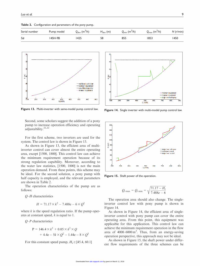
Second, some scholars suggest the addition of a ponypump to increase operation efficiency and operatingadjustability.21,22
For the first scheme, two inverters are used for thesystem. The control law is shown in Figure 13.
As shown in Figure 13, the efficient area of multi-inverter control can cover almost the entire operatingarea, except [1500, 1800]. This control law can achievethe minimum requirement operation because of itsstrong regulation capability. Moreover, according tothe water law statistics, [1500, 1800] is not the mainoperation demand. From these points, this scheme maybe ideal. For the second solution, a pony pump withhalf capacity is employed, and the relevant parametersare shown in Table 2.
The operation characteristics of the pump are asfollows:
Q–H characteristics
H =71:173 k2 � 7:488e� 63 Q2
where k is the speed regulation ratio. If the pump oper-ates at constant speed, k is equal to 1.
Q–P characteristics
P=146:43 k3 + 0:053 k2 3 Q
+4:4e� 5k 3 Q2 � 1:44e� 83 Q3
For this constant speed pump, He2 [45.4, 60.1]
Qvmax =Qvmin =
ffiffiffiffiffiffiffiffiffiffiffiffiffiffiffiffiffiffiffiffiffiffi71:17� He
7:488e� 6
r
The operation area should also change. The single-inverter control law with pony pump is shown inFigure 14.
As shown in Figure 14, the efficient area of single-inverter control with pony pump can cover the entireoperating area. From this point, this equipment wasapplicable for this application. This control law canachieve the minimum requirement operation in the flowarea of 4000–6000m3. Thus, from an energy-savingoperation perspective, this approach may not be ideal.
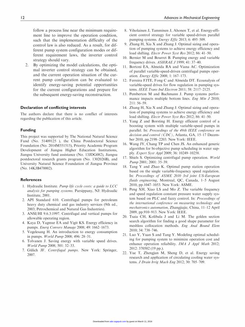
As shown in Figure 15, the shaft power under differ-ent flow requirements of the three schemes can be
Table 2. Configuration and parameters of the pony pump.
Serial number Pump model Qden (m3/h) Hden (m) Qmin (m3/h) Qmax (m3/h) N (r/min)
5# 14SH-9B 1425 58 855 1853 1450
Figure 13. Multi-inverter with same-model pump control law. Figure 14. Single inverter with multi-model pump control law.
Figure 15. Shaft power of the operation.
Luo et al. 9
by guest on March 11, 2016ade.sagepub.comDownloaded from

calculated using the optimal control law model. Basedon shaft power data shown in Table 3, the multi-inver-ter control can gain the best energy-saving effect, andthe signal inverter with pony pump also has an advan-tage over the form scheme.
For the economic analysis, the implementation costsand the energy consumption within a certain periodmust be calculated according to the flow demand prin-ciple of the pumping system. This study uses a 1-yearoperation condition as shown in Figure 10. Based onFigure 15, the annual power consumption can becomputed.
Given that the common industry electrovalenceamounts to 0.6 Yuan and that the configuration of theinvert with 10 kV and 710kW amounts to 150 millionYuan, the transition pump, high-voltage electromotor,and installation costs amount to a total of 25 millionYuan. Table 4 shows the general expenses of these dif-ferent schemes based on the cost–benefit ratio. Byassuming that the machine is free from any compro-mise, the relationship between time and gain can beobserved as shown in Figure 16.
The same figure shows that the single-invert config-uration scheme achieves the optimum profit with aworking period of less than 5 years. However, the sin-gle invert with pony pump configuration achieves thebest gain with an operation time that exceeds 20 years.Therefore, the single invert with pony pump configura-tion is applied in this energy-saving project. Finally, thecomprehensive energy-saving rate is 14% by the third-party testing.
Comparative analysis between optimal invert controllaw with other law
The most popular invert control law is the constantpressure mode and the variable pressure mode followed
minimum requirement line. All the invert control lawsare shown in Figure 17. As the constant pressure modewould cause lots of waste in pressure, which would
Table 3. Total energy consumption under different schemes.
Scheme Power consumption (kW h) Energy-saving rate (annual) (%)
Original scheme 9,075,400Single inverter configuration 1,329,500 14.6Single inverter with pony 1,434,100 15.8Two inverter configuration 1,504,800 16.6
Table 4. Total energy consumption under different schemes.
Scheme Electrovalence (million Yuan) Save Investment cost Payback time (year)
Original scheme 5.45Single inverter 4.65 0.7977 1.5 1.8Single inverter with pony 4.6 0.84138 1.75 2Two inverter 4.54 0.91572 3 3.3
-5
0
5
10
15
20
25
0 5 10 15 20 25 30
Gain
(MIllo
n RM
B)
Year
Single inverter Single with pony mul�
Figure 16. Relationship between time and gain.
Figure 17. Multi-control laws for single invert with pony pumpconfiguration.
10 Advances in Mechanical Engineering
by guest on March 11, 2016ade.sagepub.comDownloaded from

cause serious energy waste obviously, as a result, theconstant pressure mode was not considered in schemecomparison.
The shaft power under different flow requirementsof the three schemes can be calculated using the differ-ent control law models as shown in Figure 18. In mostoperation area, the shaft power was almost the same;however, in some area, the minimum requirementmight be smaller than the optimal law.
For the economic analysis, the flow demand princi-ple of the pumping system is also shown in Figure 10.
Then the annual power consumption is computed inTable 5.
From Table 5, the minimum requirement controlmight get better energy-saving effort than optimalinvert control law. So it may be ideal for energy savingfollowing minimum requirement control. But the opti-mal invert control law could also achieve good results.At the same time, the capability for efficient operationin the whole flow range for minimum requirements wasjust about 61.5%. Which means it could not enablepump to operate in reliable condition, whereas the opti-mal control law could cover 100% for the whole flowrange in efficient and reliable condition as shown inFigure 19. In short, the optimal invert control lawcould ensure the pump meet the basis of high effi-ciency, reliable to save energy as far as possible at thesame time.
Conclusion
In this work, a new model for an optimal inverter con-trol strategy based on the current system configurationand system requirements is presented. The main conclu-sions of this study are as follows:
1. The optimal inverter control strategy shouldcause the pump operation in an efficient area to
Figure 19. Efficient area operation ability of multi-control law with pony pump configuration: (a) region of efficient operation and(b) ability of efficient operation.
Table 5. Total energy consumption under different controls.
Scheme Power consumption (kW h) Energy-saving rate (annual) (%)
Original configuration 9,075,400Optimal invert control law 1,434,100 15.8Minimum requirement control 1,461,100 16.1
Figure 18. Shaft power of multi-control law with pony pumpconfiguration.
Luo et al. 11
by guest on March 11, 2016ade.sagepub.comDownloaded from
follow a process line near the minimum require-ment line to improve the operation condition,such that the implementation difficulty of thecontrol law is also reduced. As a result, for dif-ferent pump system configuration modes or dif-ferent requirement laws, the inverter controlstrategy should vary.
2. By optimizing the model calculations, the opti-mal inverter control strategy can be obtained,and the current operation situation of the cur-rent pump configuration can be evaluated toidentify energy-saving potential opportunitiesfor the current configurations and prepare forthe subsequent energy-saving reconstruction.
Declaration of conflicting interests
The authors declare that there is no conflict of interestsregarding the publication of this article.
Funding
This project was supported by The National Natural ScienceFund (No. 51409125 ), the China Postdoctoral ScienceFoundation (No. 2014M551515), Priority Academic ProgramDevelopment of Jiangsu Higher Education Institutions,Jiangsu University fund assistance (No. 13JDG082), Jiangsupostdoctoral research grants program (No. 1302026B), andUniversity Natural Science Foundation of Jiangsu Province(No. 14KJB470002).
References
1. Hydraulic Institute. Pump life cycle costs: a guide to LCC
analysis for pumping systems. Parsippany, NJ: Hydraulic
Institute, 2001.2. API Standard 610. Centrifugal pumps for petroleum
heavy duty chemical and gas industry services (9th ed.,
2003; Petrochemical and Natural Gas Industries).3. ANSI/HI 9.6.3:1997. Centrifugal and vertical pumps for
allowable operating region.4. Kaya D, Yagmur EA and Yigit KS. Energy efficiency in
pumps. Energ Convers Manage 2008; 49: 1662–1673.5. Vogelesang H. An introduction to energy consumption
in pumps. World Pump 2008; 496: 28–31.6. Tolvanen J. Saving energy with variable speed drives.
World Pump 2008; 501: 32–33.7. Gulich JF. Centrifugal pumps. New York: Springer,
2007.
8. Viholainen J, Tamminen J, Ahonen T, et al. Energy-effi-cient control strategy for variable speed-driven parallel
pumping systems. Energy Effic 2013; 6: 495–509.9. Zhang H, Xia X and Zhang J. Optimal sizing and opera-
tion of pumping systems to achieve energy efficiency andload shifting. Electr Power Syst Res 2012; 86: 41–50.
10. Bernier M and Bourret B. Pumping energy and variable
frequency drives. ASHRAE J 1999; 41: 37–40.11. Bortoni EA, Almeida RA and Viana AC. Optimization
of parallel variable-speed-driven centrifugal pumps oper-
ation. Energy Effic 2008; 1: 167–173.12. Ferreira FJTE, Fong C and Almeida DT. Ecoanalysis of
variable-speed drives for flow regulation in pumping sys-tems. IEEE Trans Ind Electron 2011; 58: 2117–2125.
13. Pemberton M and Bachmann J. Pump systems perfor-
mance impacts multiple bottom lines. Eng Min J 2010;211: 56–59.
14. Zhang H, Xia X and Zhang J. Optimal sizing and opera-tion of pumping systems to achieve energy efficiency and
load shifting. Electr Power Syst Res 2012; 86: 41–50.15. Yang Z and Borsting H. Energy efficient control of a
boosting system with multiple variable-speed pumps in
parallel. In: Proceedings of the 49th IEEE conference on
decision and control (CDC), Atlanta, GA, 15–17 Decem-ber 2010, pp.2198–2203. New York: IEEE.
16. Wang JY, Chang TP and Chen JS. An enhanced generic
algorithm for bi-objective pump scheduling in water sup-ply. Expert Syst Appl 2009; 36: 10249–10258.
17. Shiels S. Optimizing centrifugal pump operation. World
Pump 2001; 2001: 35–39.18. Tang Y and Zhao K. Optimal pump station operation
based on the single variable-frequency speed regulation.In: Proceedings of ASME 2010 3rd joint US-European
fluids engineering, Montreal, QC, Canada, 1–5 August2010, pp.1047–1053. New York: ASME.
19. Peng XH, Xiao LS and Mo Z. The variable frequencyand speed regulation constant pressure water supply sys-
tem based on PLC and fuzzy control. In: Proceedings ofthe international conference on measuring technology and
mechatronics automation, Zhangjiajie, China, 11–12 April
2009, pp.910–913. New York: IEEE.20. Tsaia CH, Kolibala J and Li M. The golden section
search algorithm for finding a good shape parameter for
meshless collocation methods. Eng Anal Bound Elem
2010; 34: 738–746.21. Luo Y, Yuan S and Tang Y. Modeling optimal schedul-
ing for pumping system to minimize operation cost and
enhance operation reliability. IMA J Appl Math 2012;2012: 370502 (19 pp.).
22. Yue T, Zhengjun M, Sheng D, et al. Energy saving
research and application of circulating cooling water sys-
tems. J Drain Irrig Mach Eng 2012; 30: 705–709.
12 Advances in Mechanical Engineering
by guest on March 11, 2016ade.sagepub.comDownloaded from