Embed Size (px)
Citation preview
ENERGY PRODUCTION AND DISTRIBUTION
Dr. Dezső Nagy
BME, Dept. of Control Engineering and Information Technology
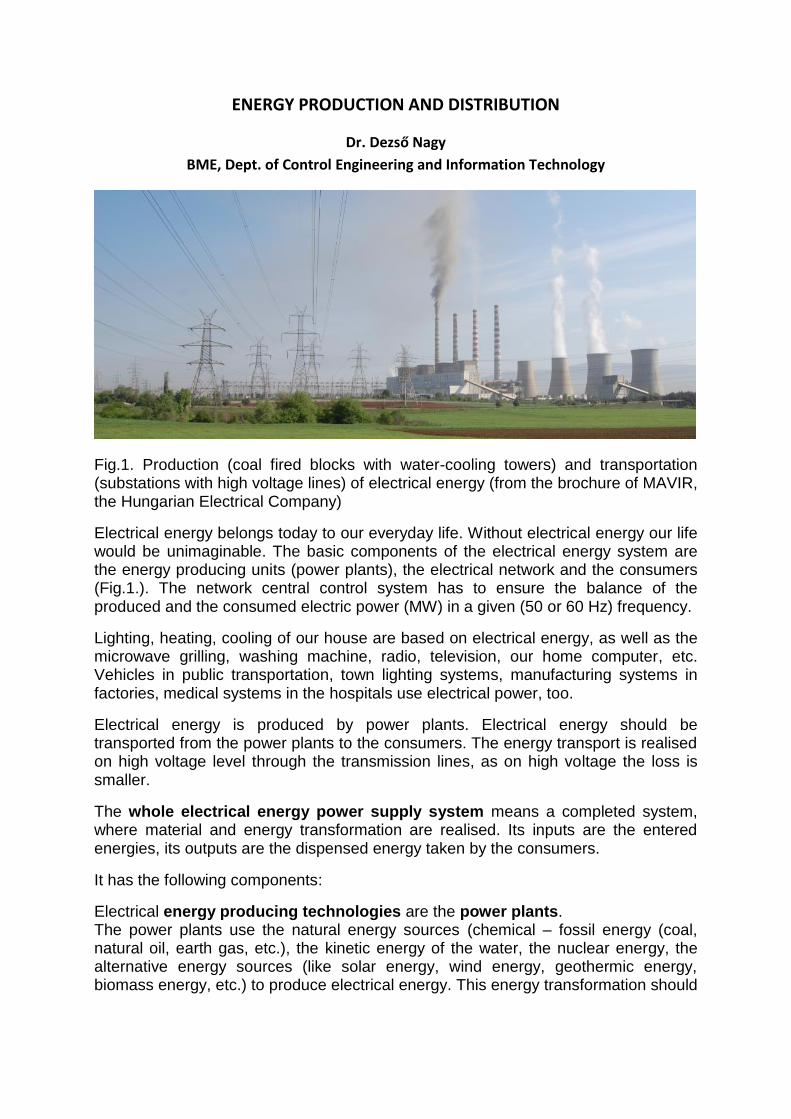
Fig.1. Production (coal fired blocks with water-cooling towers) and transportation (substations with high voltage lines) of electrical energy (from the brochure of MAVIR, the Hungarian Electrical Company)
Electrical energy belongs today to our everyday life. Without electrical energy our life would be unimaginable. The basic components of the electrical energy system are the energy producing units (power plants), the electrical network and the consumers (Fig.1.). The network central control system has to ensure the balance of the produced and the consumed electric power (MW) in a given (50 or 60 Hz) frequency.
Lighting, heating, cooling of our house are based on electrical energy, as well as the microwave grilling, washing machine, radio, television, our home computer, etc. Vehicles in public transportation, town lighting systems, manufacturing systems in factories, medical systems in the hospitals use electrical power, too.
Electrical energy is produced by power plants. Electrical energy should be transported from the power plants to the consumers. The energy transport is realised on high voltage level through the transmission lines, as on high voltage the loss is smaller.
The whole electrical energy power supply system means a completed system, where material and energy transformation are realised. Its inputs are the entered energies, its outputs are the dispensed energy taken by the consumers.
It has the following components:
Electrical energy producing technologies are the power plants. The power plants use the natural energy sources (chemical – fossil energy (coal, natural oil, earth gas, etc.), the kinetic energy of the water, the nuclear energy, the alternative energy sources (like solar energy, wind energy, geothermic energy, biomass energy, etc.) to produce electrical energy. This energy transformation should

have optimal efficiency. The electrical power should be ensured for the consumers at stable voltage level and frequency.
Electrical energy network. The energy transport will be realised in the network on high voltage level, because the same power needs lower current on high voltage, and the loss of transportation is proportional to the quadrat of the current. Moreover the cross-section of the power line will be smaller, but because of the high voltage the column sizes should be greater. In the power plant substations the middle voltage will be transformed into high voltage by transformers and connected to the high voltage transmission lines. In the substations the transformers reduce the high voltage into middle voltage and low voltage back for the consumers.
The electrical energy network consists of low voltage part (up to 1kV), middle voltage part (10, 20, 30kV) and high voltage part (120kV, 220kV, 400kV, 750kV). The electrical energy transported on high voltage will be transformed into middle voltage level in the substations for the industrial consumers, and for the institutional and household consumers to the required voltage level.
Consumers of the electrical energy supply system:
The consumers of the electrical energy system are the big state consumers, communal consumers (town lighting, public transportation, police and military consumers) generally on middle voltage, sometimes on low voltage level. The civil and industrial consumers (factories, productive firms, households, etc.) need energy mostly on low level voltage energy, sometimes on middle level.
The electric power dispatching system
The main task of the dispatching system is to ensure the balance of the produced and consumed electrical energy on a given stable voltage level and frequency. The electrical network working with alternating voltage is not able to store electrical energy. For this reason in case of unbalanced situation the Central Dispatching Centre modifies the produced power by the power plants to ensure in each second the equilibrium of the produced and the consumed electrical power within the network.
In Hungary the owner of the Basic High Voltage Network is the MAGYAR VILLAMOS MŰVEK RT, the operation of the Network is managed and controlled by the Magyar Villamosenergia-ipari Rendszerirányító ZRT (MAVIR ZRT).
The energy producing and dispatching system can be considered as a system whose input is the input energy (chemical, solar, etc.) transformed by the power plants into electrical power and then transported to the consumers. The output is the energy appearing on the consumer’s level and the physical parameters of the consumer equipment applying this energy.
On the other hand the electrical energy producing and dispatching system can be handled as a complex system consisting of subsystems. Analysing the subsystems the system and its environment, the inputs and the outputs should be defined again. For instance the power plant has inputs, like the entered power (chemical, water, nuclear, alternative, etc.) and outputs, like the electrical power with a given voltage and frequency. These outputs should be controlled to have a given accuracy and

reliability according to the time scheduled requirements depending from the seasons, daily consumptions, etc. The substation can be considered as a subsystem whose input is the input voltage and its output is the transformed voltage. The process is determined by the operation of the transformer. The next subsystem is the transmission line. It transports the electrical energy. The transport process has time delay, so-called dead time. The consumer is the last subsystem of the power supply process, which can be examined separately. Its input is the electrical power, its outputs are the outputs of the consuming device (temperature, angular velocity, etc.). In the sequel the models of two subsystems will be given. The first subsystem will be the boiler-turbine-generator model of the coal fired power plant block. The second model to be examined is the network model connected to energy producing and consuming units.
Boiler – turbine – generator model
source: http://www.tva.gov/power/coalart.htm
Fig.2. Scheme of coal fired power plant
In case of coal fired power plant the coal will be transported from the coal mine to the power plant boiler, the coal will be grinded then transported into the fire room then fired, producing steam. The high-pressure steam will be introduced into the turbine driving it. The heat power will be transformed into mechanical power, then by the generator into electrical power. The transformer connected after the generator transforms electrical power for the high voltage network. Fig. 2. demonstrates this process.
The simplified structural model is shown in Fig 3. The model is a special version made for the investigation of the block primer control.
Fig.3 shows the simplified structural scheme of a power plant block (boiler and turbine), the so called power control with active turbine. In this scheme the turbine has the primary role, as the turbine controller gets the MW set point and modifies the turbine inlet valve position.
If the MW set point is greater than the actual, measured MW value, the turbine controller (PI) opens the turbine control valve and the increasing steam flow

increases the generator MW while the measured MW and the set point MW will be equal. But as the consumed steam is greater than the boiler produced steam, so the boiler outlet pressure will decrease. The boiler outlet steam controller (PI) increases the speed of the coal supplier motor and the increased fuel flow increases the produced steam flow, until the required and produced MW will be equal.
Fig.3. Simplified scheme of a power plant block
To analyse the operation of the block MW control it is necessary to describe the dynamical behaviour of each element. Each sub process is given by mathematical blocks (described with transfer functions or differential equations, static characteristics, which give the relationship between the steady state values of the outputs and those of the inputs). These blocks are connected to each other according to the control scheme. This is the block diagram (signal flow diagram) of the process. Fig.4. shows the block diagram of the power plant given in Fig. 3. To create this diagram the following considerations were used. The boiler coal supplier gets the output signal of the boiler outlet pressure (PI) controller in % for its input, The steam generator can be approximated with a first order time delay block with dead time, its output is the produced steam flow (T/H). The superheater takes away the produced steam. The integral of the difference of the superheater input and output steam flow provides the drum pressure. The integral of the difference of the boiler outlet steam flow and the turbine inlet steam flow gives the fresh steam pressure. The superheater outlet steam flow is proportional to the square root of the drum pressure considering also the turbine ventil position. The block MW controller (taking into consideration the primary control effect) modifies the input flow of the turbine according to the MW control difference. This steam flow change modifies the boiler output pressure then the boiler pressure controller modifies the fuel flow. The deviation of the actual frequency and the frequency setpoint multiplied by a K factor will be added to the MW setpoint. This realises the so called primary frequency control function.

Fig 4. Block diagram of the control scheme of the energy producing block
On the basis of the block diagram the static and dynamical behaviour of the control system can be investigated. It can be checked weather the scheme fulfil the requirements of qualified operation. It is easy to modify the control parameters and to analyse the dynamical features of the control system. It is worthwhile to make a simulation before the construction of the final realisation.
Network model connected to energy producing and energy consuming units
The main task of the electrical power supply system is to ensure the balance of the produced and consumed electrical energy on a stable voltage level and frequency. The electrical network working with alternating voltage is not able to store electrical energy. The Central Dispatching Centre modifies the produced power by the power plants and consumed power of the consumers to ensure in each second the equilibrium of the produced and consumed electrical power within the network. In this way the power plants have to execute the commands coming from the Central Dispatching Centre.
First an overview scheme will be given about the national network. The national subnetworks are connected to the common national network. This national network is operating according to an agreement with outer partners taking into consideration the load exchange schedule. The system is prepared for different network disturbances and malfunction situations as well. Now the MW power control will be discussed only, the MVAR controlling and the disturbance management are not discussed here.
Model of electrical MW power producers and consumers connected to the Central Dispatching Centre
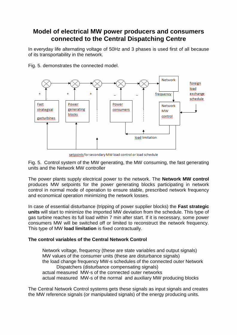
In everyday life alternating voltage of 50Hz and 3 phases is used first of all because of its transportability in the network. Fig. 5. demonstrates the connected model.
Fig. 5. Control system of the MW generating, the MW consuming, the fast generating units and the Network MW controller The power plants supply electrical power to the network. The Network MW control produces MW setpoints for the power generating blocks participating in network control in normal mode of operation to ensure stable, prescribed network frequency and economical operation minimizing the network losses. In case of essential disturbance (tripping of power supplier blocks) the Fast strategic units will start to minimize the imported MW deviation from the schedule. This type of gas turbine reaches its full load within 7 min after start. If it is necessary, some power consumers MW will be switched off or limited to reconstruct the network frequency. This type of MW load limitation is fixed contractually. The control variables of the Central Network Control
Network voltage, frequency (these are state variables and output signals) MW values of the consumer units (these are disturbance signals)
the load change frequency MW-s schedules of the connected outer Network Dispatchers (disturbance compensating signals) actual measured MW-s of the connected outer networks actual measured MW-s of the normal and auxiliary MW producing blocks
The Central Network Control systems gets these signals as input signals and creates the MW reference signals (or manipulated signals) of the energy producing units.

Operation of the network control
The main task of the network MW control is to ensure the balance of the produced
and consumed electrical energy with a stable voltage level and frequency. The
electrical network working with alternating voltage is not able to store electrical
energy. For this reason in case of unbalanced situation the Central Dispatching
Centre modifies the produced power by the power plants to ensure in each second
the equilibrium of the produced and consumed electrical power within the network.
Primary network control
The Block MW controller may have the following duties according to the designer
requirements:
Fast reaction (within 5-10 sec) to the network frequency changes in case of
disturbance. This is the so called k*DF additive to the turbo generator MW set
point and in this case the block participates to balance the power equilibrium of
the network. (usage the network frequency)
Load change caused by the primary network control does not set back the
frequency, this is the task of the secondary control, modifying the block MW-s
participating in the secondary control.
Secondary network control
The blocks in Fig.5. can participate in the so called secondary MW control of
the network, getting electrical energy setpoint (MWHour) for instants or every
minute, or for 15 minute time period from the central network MW control.
The secondary MW control has the task to realise the equilibrium of the produced and consumed MW in the network within 10-20 minutes resetting the 50 Hz network frequency. The MW supplier (the power plant) gives continuously a low and high limit for the setpoint and limits for their MW value and MW speed change, too. (using the Sec MW setpoint). To the MW set point pro minute the Network control Centre calculates the
necessary setpoint needed to the equilibrium of the supplied and consumed
power, considering the MW exchange schedule with foreign networks and of
the economically optimal operation.
The power plant agrees with the Network control Centre for the MW schedule
for the next day (for instance) with 15 min periods. This means, the block
receives in the next day for each 15 min time period the agreed MWhour
electric energy setpoint. Keeping the schedule will be well paid but all
deviations will be strictly punished (even the + deviation; the +deviation will be
paid with lower price). This is the usage of the schedule.

There is a third version for the central load dispatching, this is the so called
tercier network control, but it is first of all the job of the Central MW Control.
That means, that at the calculation of the secondary setpoints for the power
plants not only the equilibrium will be considered, but also the economic
factors of network operation (network losses, other economic factors of the
power plants and network). In this way the tercier network control has the
possibility to reach an economic operation optimum.
The next example shows the cooperation between one power plant block as a subsystem and the Central Network MW control.
Power plant block cooperation with the Central MW control The Central Network control produces MW setpoints for the power generating blocks
in normal mode of operation to ensure stable, prescribed network frequency.
Fig. 6. shows the simplified scheme of a power plant block working with the Network
MW Control.
Fig. 6. Simplified scheme of power plant block working with the Network MW Control
The typical power plant block consists of boiler, turbine, generator subsystems, block
Power Controller and is connected to the network with high voltage electrical line,
then to the Central Network MW Control with BlockMWcontroller.
The BlockMWcontroller receives to the cooperation needed signals, the MW
schedule, the secondary control setpoint, arriving from the Network MW control, the
network frequency and the needed boiler and turbine signals, which are needed to
the primer controller built into the blockMWcontroller.
The blockMWcontroller controls the turbine steamflow (and the generator MW) with
the turbine MW control, the boiler outlet steam pressure with the boiler fuel flow

control. The energy producing blocks supply their power into the National Electric
Basis network.
Some photos (fig 7.-10.) from the MAVIR ZRT documentation about some parts of
the energy supply system:
Fig .7. Power Plant Dunamenti from height
Fig.8. Substation Göd

Fig.9. Transmission line Szombathely
Fig.10. Transformer, 750kV
The Hungarian Electrical Power System and the load
exchange with the neighbouring countries
The first level of the electrical power system is the high voltage transmission network, which consists mostly of 400kV transmission lines. The basic power plants are connected to this network. The transmission lines crossing the boards are parts of the transmission network. The electrical power exchange among the neighbouring countries is executed through these transmission lines according to the trade agreements. The owner of the high voltage transmission network is MAVIR ZRT. The second level is the 120kV main dispatching network managed and operated by the current supplier firms, which ensure the electrical energy transport to the bigger consumer nodes (towns, districts, large-scale consumers). The main dispatching network receives the electrical power from the node-substations of the transmission network.

The local dispatching networks belong to the third level. These networks supply their consumers from the main dispatching network first on middle voltage (10 and 20kV), then on low voltage level (400/230V). The middle and low voltage dispatching networks are operated also by the current supplier firms. The main parts of the high voltage substations are the highpower transformers, the switchgears of the primary and secondary side, the controller and breakdown devices controlling them. These substations are located mostly out of towns, in outdoor closed area. In larger towns they are located in municipal indoor area. The low or middle voltage dispatching transformers and switchgears are located either on columns - built for this purpose -, or in special street containers, or closed area of buildings. The scheme of the Hungarian transmission network can be seen on Fig.11.
Fig. 11. The Hungarian transmission network The Hungarian electrical energy system belongs to the RGCE – the union of electrical energy systems of 24 countries. This unified system ensures technically the standardised operation of the internal current market of EU. The current exchange in Hungary with our neighbouring countries is operating within this system, controlled by

MAVIR. The actual diagram of the electrical energy exchange can be seen on the homepage of MAVIR (Fig. 12.). http://www.mavir.hu/web/mavir/home
Fig.12. Exchange of electrical energy with the neighbouring countries
Conventional and renewed energy sources The production and distribution of electrical energy has first class importance and it is a basic condition of our everyday life. Nowadays the alternative and renewed energy sources have more and more importance besides the utilisation of the conventional coal, oil, gas and water energies. The amount of chemical energy sources is limited, therefore the elaboration of safe and economical usage of the renewed, alternative energies is very important. The basic units of the power plants are the turbine and the synchronous generator. Rotating the blades of the turbine its shaft will start rotating. The shaft of the turbine is connected to the shaft of the synchronous generator. The coil of the rotor of the synchronous generator is energised with direct current or by a permanent magnet. On the stator there is a multiphase alternating current coil system. The rotating magnetic field generates alternating voltage in the stator coils. The synchronous generator transforms the mechanical energy into electrical energy. The different power plants transform the available chemical, water, nuclear or alternative energy into mechanical energy, the rotating energy of the turbine.

The E.O.N. Hungaria ZRT- a basic participant of the Hungarian economy and leader energy supplier of Hungary - elaborated a great class learning program called Energiakaland (Energyadventure). Its goal is to create energy-consciousness, to increase the knowledge about energy for everybody, from nursery upto adults. The following link shows spectacular explanation of the usage of the energy sources, their transformation into electrical energy. Animations help understanding. http://www.energiakaland.hu/energiaotthon/energiaforrasok
The next part gives a short description of the operation principle of the different power plants. Coal fired power plant The heat power produced by burning coal or lignit in a furnace will heat the water. Thus steam will be generated, which actuating the blades of the turbine rotates them. The rotating turbine shaft connected to the generator produces electrical current. Power plant using oil The oil is burned in a boiler. The heat power warms the water generating steam, which introduced to the blades of the turbine rotates them. The rotating turbine shaft connected to the generator produces electrical current. Gas turbine with heat recovery boiler The gas is burned in big gas turbines. The turbine rotates the generator, which generates electrical energy. The hot smoke leaving the gas turbine enters a heat recovery boiler producing steam and it drives a steam turbine with generator producing electrical current again. This technology has better efficiency. The heat recovery boiler’s steam can be used for remote heating of buildings. Water power plant built on river or using water storage Water power plants are built on rivers where because of the existing height difference or height difference ensured by water reservoirs the falling water rotates the turbines generating electrical power. Nuclear power plant The atomic energy is generated by the fission of the uranium atoms into smaller size atoms. The uranium is bombed by neutrons causing nucleon splitting. During nucleon splitting free neutrons will be produced which split newer nucleons, so chain reaction is trigged and significant amount of heat energy is released. To limit the chain reaction in order to avoid nuclear explosion and to make the process controllable and self-sustaining a moderator material is used, which brakes the neutrons. In former power plants graphite was used as moderator. Nowadays in the second generation reactors with pressured water light water is used as moderator (e.g. also in Paks).These plants use artificially enriched uranium as fuel. The energy coming from the fission of the uranium is used for water warming. Steam is produced, which

pressurises the turbine blades which rotate the turbine shaft connected to the generator. The rotating generator produces current. Further links: http://www.fordulo-portal.hu/index.php?page=news&id=26 http://aramhasznalok.network.hu/blog/villamosenergia-felhasznalok-kozossege-hirei/a-villamos-energia-eloallitasanak-modjai-atomeromu
Usage of alternative, renewed energy sources The limitation of the fossil energy sources (coal, crude oil, gas) and of water increases the importance of the usage of alternative, renewable energy sources for production of electrical energy. In the sequel some of them will be mentioned. Windturbine Wind causes pressure difference between the frontside and the backside of the windturbine blades which rotates the windturbine connected to the generator producing current. Solar plant The energy of the light is transformed into electrical energy by means of solar elements. These solar cells are connected into solar cell panels. The solar cell panels are mounted on the top or the sidewall of the building. The solar collectors produce warm water in the water heaters simply. Within the black solar collector tubes - positioned toward the sun - water is circulating and heated by sunshine. In the heat exchanger of the house the warmed up water gives its heat energy to the cooler water circulating in the pipeline of the house ensuring the heating. Biomass power plant All materials of animal or plant origin are parts of the biomass. There are special biomass plants, the so called energy plants which can be used as heating material. The biomass is burned in special steamboilers. The generated steam rotates a turbine with generator producing electrical energy. Metan gas can be obtained from the wastewater of a town. By burning this gas heat energy and electrical energy is produced. Usage of the geothermal energy The water in some places – deep under the earth level – is warmed up and raising up as hot spring water it can be used also as geothermic heat. Water can be pumped into artificial wells, drilled into the deeply under the earth level located high temperature areas. When the water is warmed up, it will be pumped up. Bringing up the hot water it can be used for heating houses, or if it is not hot enough, for steam generating for turbines. Using of hydrogen fuel cells If electrical current is introduced into water, the bonds of the water molecules will be decomposed to oxygen and hydrogen. The oxygen and hydrogen will leave the

electrolysis in form of gas. The opposite process will occur in the fuel cell. The fuel cells produce water from hydrogen and oxygen and create electrical current and heat energy during this process. Theoretically the process can be executed from the oxygen being in air and from the hydrogen being in water anywhere. The fuel cell is an energy storing device (special form of accumulator), which produces electrical current from hydrogen and from the oxygen existing in the air, and water is produced as a secondary effect. The fuel cells as products nowadays are in experimental phase. They are advantageous compared to the conventional accumulators, because they can store much more energy in the same volume and with the same weight.
References
Geszti P. Ottó: Villamosenergia rendszerek I-II, Tankönyvkiadó, 1984. Czinder Jenő: Erőművek szabályozása, Műegyetemi Kiadó, 2000. Faludi Andor, Szabó László: Villamosenergia rendszer üzeme és iranyitása, BMEVIVEM265, 2011. Jenő Kovács, Foster Wheeler Finnland: Advances in Coordinated Control, Powerplant Application of Advanced Control Technics. Editor: Pál Szentannai, 2010.