Embed Size (px)
Citation preview
Available online at www.sciencedirect.com
www.elsevier.com/locate/actamat
Acta Materialia 59 (2011) 283–296
Energy of slip transmission and nucleation at grain boundaries
Michael D. Sangid a, Tawhid Ezaz a, Huseyin Sehitoglu a,⇑, Ian M. Robertson b
a Department of Mechanical Science and Engineering, University of Illinois at Urbana-Champaign, 1206 W. Green St., Urbana, IL 61801, USAb Department of Material Science and Engineering, University of Illinois at Urbana-Champaign, 1304 W. Green St., Urbana, IL 61801, USA
Received 25 March 2010; received in revised form 14 September 2010; accepted 16 September 2010Available online 19 October 2010
Abstract
Grain boundaries (GBs) provide a strengthening mechanism in engineering materials by impeding dislocation motion. In a polycrys-talline material, there is a wide distribution of GB types with characteristic slip transmission and nucleation behaviors. Slip–GB reactionsare not easy to establish analytically or from experiments; furthermore, there is a strong need to quantify the energy barriers of the indi-vidual GBs. We introduce a methodology to calculate the energy barriers during slip–GB interaction, in concurrence with the generalizedstacking fault energy curve for slip in a perfect face-centered cubic material. By doing so, the energy barriers are obtained at variousclassifications of GBs for dislocation transmission through the GB and dislocation nucleation from the GB. The character and structureof the GB plays an important role in impeding slip within the material. The coherent twin (R3) boundary provides the highest barrier toslip transmission. From this analysis, we show that there is a strong correlation between the energy barrier and interfacial boundaryenergy. GBs with lower static interfacial energy offer a stronger barrier against slip transmission and nucleation at the GB. The resultsof our simulations are in agreement with experimental observations as demonstrated for R3, R13 and R19 boundaries. The R3 GB rep-resents a higher-energy barrier compared to the R13 and R19 GBs, where, for the latter case, complex stacking fault structures are presentin experiments and simulations.� 2010 Acta Materialia Inc. Published by Elsevier Ltd. All rights reserved.
Keywords: Grain boundary energy; Molecular dynamics simulations (MD simulations); Coincidence site lattice (CSL); Dislocation; Slip
1. Introduction
It is well established that grain boundaries (GBs) offer asubstantial strengthening mechanism within materials [1].At the atomic level, the physics of the energy barriers pro-duced by GBs is still an unresolved issue, including the indi-vidual strengthening benefit of various types of GBs. Theseenergy barriers are essential to the understanding of plasticdeformation and have tremendous implications, especiallyfor failure mechanisms such as fatigue, fracture and creep.In classical treatments, GBs were proposed to impede dislo-cation motion resulting in pile-ups at the GB, which in turnprovides a stress concentration that activates dislocationsources in neighboring grains [2,3]. In later works, the focushas been on incident dislocations reactions with GBs, which
1359-6454/$36.00 � 2010 Acta Materialia Inc. Published by Elsevier Ltd. All
doi:10.1016/j.actamat.2010.09.032
⇑ Corresponding author. Tel.: +1 217 333 4112; fax: +1 217 244 6534.E-mail address: [email protected] (H. Sehitoglu).
produce residual dislocations at the interface [1] and modifythe energy barriers for incorporation and transmission pro-cesses. The precise magnitude of the energy barriers, as influ-enced by the underlying reactions and obstacles, has notbeen established previously and is the main focus of thiswork. Specifically, the relative magnitudes of energy barriersfor transmission vs. nucleation are highlighted for varioustypes of GBs.
The role that individual interfaces play on the mechanicalbehavior of a material is a very hard phenomenon to observeexperimentally. To simplify this analysis, many experimentshave been conducted on a bicrystal, which allows researchersto study deformation and incompatibilities across a singlegrain boundary [1,4]. The research of Livingston andChalmers [5] created a criterion for slip across a grain bound-ary based on the geometry of the system. This geometricalcriterion was extended by Shen, Wagoner and Clark in1986, who noted that the resolved shear stress should bemaximized [6]. In 1989, Lee, Robertson and Birnbaum
rights reserved.
284 M.D. Sangid et al. / Acta Materialia 59 (2011) 283–296
(LRB) proposed the addition of a third requirement, namelythat the residual dislocation in the grain boundary be mini-mized [7]. The aforementioned studies [5–7] are very valuableand outline strain incompatibility at the grain boundary,although they do not address the energy barriers that dislo-cations must overcome to penetrate the grain boundary.
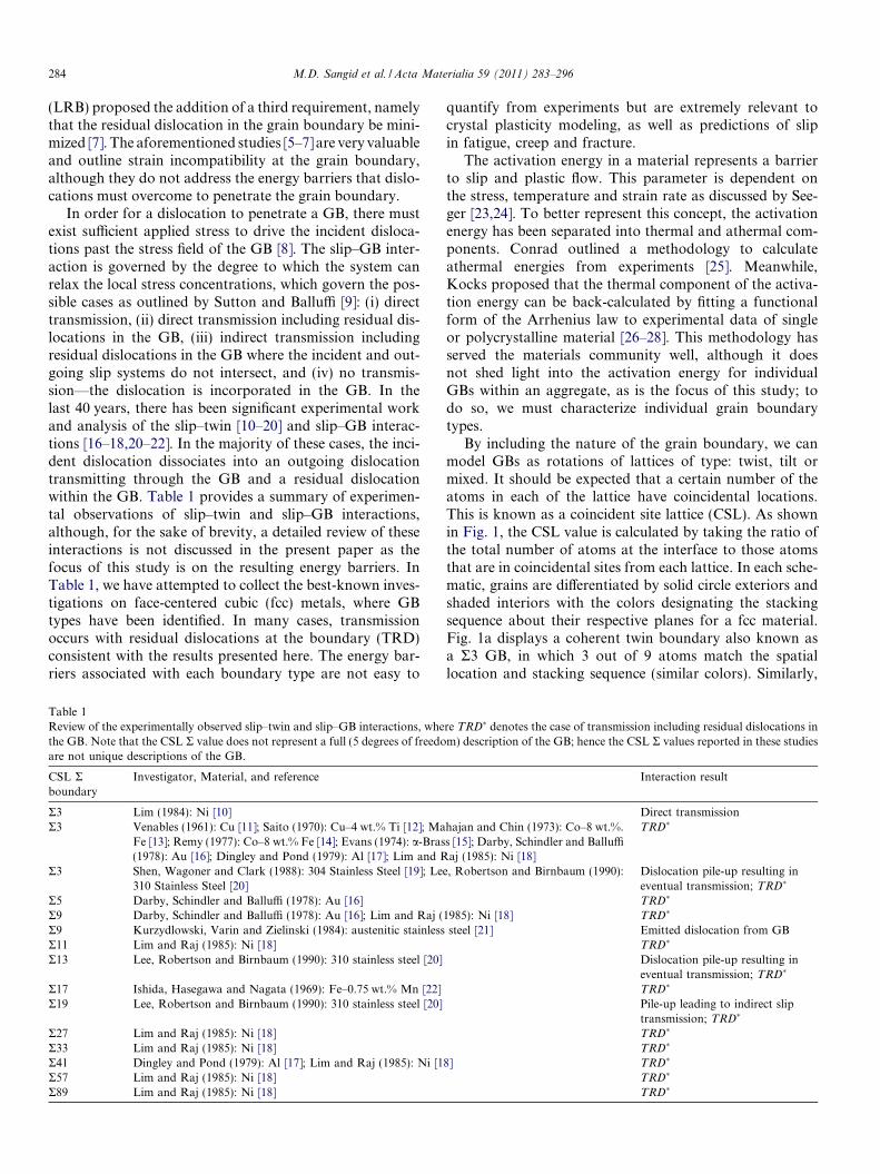
In order for a dislocation to penetrate a GB, there mustexist sufficient applied stress to drive the incident disloca-tions past the stress field of the GB [8]. The slip–GB inter-action is governed by the degree to which the system canrelax the local stress concentrations, which govern the pos-sible cases as outlined by Sutton and Balluffi [9]: (i) directtransmission, (ii) direct transmission including residual dis-locations in the GB, (iii) indirect transmission includingresidual dislocations in the GB where the incident and out-going slip systems do not intersect, and (iv) no transmis-sion—the dislocation is incorporated in the GB. In thelast 40 years, there has been significant experimental workand analysis of the slip–twin [10–20] and slip–GB interac-tions [16–18,20–22]. In the majority of these cases, the inci-dent dislocation dissociates into an outgoing dislocationtransmitting through the GB and a residual dislocationwithin the GB. Table 1 provides a summary of experimen-tal observations of slip–twin and slip–GB interactions,although, for the sake of brevity, a detailed review of theseinteractions is not discussed in the present paper as thefocus of this study is on the resulting energy barriers. InTable 1, we have attempted to collect the best-known inves-tigations on face-centered cubic (fcc) metals, where GBtypes have been identified. In many cases, transmissionoccurs with residual dislocations at the boundary (TRD)consistent with the results presented here. The energy bar-riers associated with each boundary type are not easy to
Table 1Review of the experimentally observed slip–twin and slip–GB interactions, whethe GB. Note that the CSL R value does not represent a full (5 degrees of freedoare not unique descriptions of the GB.
CSL Rboundary
Investigator, Material, and reference
R3 Lim (1984): Ni [10]R3 Venables (1961): Cu [11]; Saito (1970): Cu–4 wt.% Ti [12]; Ma
Fe [13]; Remy (1977): Co–8 wt.% Fe [14]; Evans (1974): a-Bras(1978): Au [16]; Dingley and Pond (1979): Al [17]; Lim and R
R3 Shen, Wagoner and Clark (1988): 304 Stainless Steel [19]; Le310 Stainless Steel [20]
R5 Darby, Schindler and Balluffi (1978): Au [16]R9 Darby, Schindler and Balluffi (1978): Au [16]; Lim and Raj (R9 Kurzydlowski, Varin and Zielinski (1984): austenitic stainlessR11 Lim and Raj (1985): Ni [18]R13 Lee, Robertson and Birnbaum (1990): 310 stainless steel [20]
R17 Ishida, Hasegawa and Nagata (1969): Fe–0.75 wt.% Mn [22]R19 Lee, Robertson and Birnbaum (1990): 310 stainless steel [20]
R27 Lim and Raj (1985): Ni [18]R33 Lim and Raj (1985): Ni [18]R41 Dingley and Pond (1979): Al [17]; Lim and Raj (1985): Ni [1R57 Lim and Raj (1985): Ni [18]R89 Lim and Raj (1985): Ni [18]
quantify from experiments but are extremely relevant tocrystal plasticity modeling, as well as predictions of slipin fatigue, creep and fracture.
The activation energy in a material represents a barrierto slip and plastic flow. This parameter is dependent onthe stress, temperature and strain rate as discussed by See-ger [23,24]. To better represent this concept, the activationenergy has been separated into thermal and athermal com-ponents. Conrad outlined a methodology to calculateathermal energies from experiments [25]. Meanwhile,Kocks proposed that the thermal component of the activa-tion energy can be back-calculated by fitting a functionalform of the Arrhenius law to experimental data of singleor polycrystalline material [26–28]. This methodology hasserved the materials community well, although it doesnot shed light into the activation energy for individualGBs within an aggregate, as is the focus of this study; todo so, we must characterize individual grain boundarytypes.
By including the nature of the grain boundary, we canmodel GBs as rotations of lattices of type: twist, tilt ormixed. It should be expected that a certain number of theatoms in each of the lattice have coincidental locations.This is known as a coincident site lattice (CSL). As shownin Fig. 1, the CSL value is calculated by taking the ratio ofthe total number of atoms at the interface to those atomsthat are in coincidental sites from each lattice. In each sche-matic, grains are differentiated by solid circle exteriors andshaded interiors with the colors designating the stackingsequence about their respective planes for a fcc material.Fig. 1a displays a coherent twin boundary also known asa R3 GB, in which 3 out of 9 atoms match the spatiallocation and stacking sequence (similar colors). Similarly,
re TRD� denotes the case of transmission including residual dislocations inm) description of the GB; hence the CSL R values reported in these studies
Interaction result
Direct transmissionhajan and Chin (1973): Co–8 wt.%.s [15]; Darby, Schindler and Balluffiaj (1985): Ni [18]
TRD�
e, Robertson and Birnbaum (1990): Dislocation pile-up resulting ineventual transmission; TRD�
TRD�
1985): Ni [18] TRD�
steel [21] Emitted dislocation from GBTRD�
Dislocation pile-up resulting ineventual transmission; TRD�
TRD�
Pile-up leading to indirect sliptransmission; TRD�
TRD�
TRD�
8] TRD�
TRD�
TRD�

Sigma 3: (111) plane
Sigma 7: (111) plane
Sigma 5: (001) plane
(a.) (b.)
(c.)
(d.)
Fig. 1. Schematic of CSL GBs. (a) R3 GB, coherent twin boundary (3 out of 9 atoms are in coincidence). (b) R5 GB (2 out of 10 atoms are in coincidence).(c) R7 GB (1 out of 7 atoms are in coincidence). (d) In each schematic, grain 1 is represented with solid circle exteriors, grain 2 is represented with shadedinteriors, and the stacking sequence is indicated by the various colors (ABC stacking (red, blue, black) for the (1 1 1) planes as shown in (a) and (c) and ABstacking (red, blue) for the (0 0 1) plane as shown in (b). When the symbols spatially align with similar colors, the atoms are in coincidental lattice positionsas indicated by for (a), and for (b), and for (c).
M.D. Sangid et al. / Acta Materialia 59 (2011) 283–296 285
schematics for the R5 (2 out of 10 atoms) and R7 (1 out of 7atoms) GBs are shown in Fig. 1b and c, respectively. Fur-ther, special GBs arise as a consequence of the CSL [29]. Asthe importance of the CSL became more widely recognized,the mathematics of GBs were developed to handle theirconfiguration [30].
Sutton and Vitek proposed that the GB energy be attrib-uted to the structural units that comprise the interface[31,32]. From this work, Rittner and Seidman clearlydescribed a technique for generating the GB energies forthe structure of the GBs and the resulting dislocation struc-ture [33]. The CSL configuration was adopted in these sim-ulations, where the calculations represent static energies;many of the procedures used in these studies aid the currentwork. Building on these investigations, modeling dislocationnucleation from GBs of nanocrystalline material has pro-vided insight at smaller length scales [34,35]. Although thestresses necessary to nucleate the dislocation from these pris-tine GBs were calculated correctly for ideal cases [36–39],they are much too high. The excessive value of the simula-tion stress is indicative of the molecular dynamics (MD).In the present work, we are concerned with the deformationin larger scales; thus we extract information from atomisticsimulations for modeling bulk material on the energy mag-nitudes, and circumvent the use of stress as a state variable.
There are several slip–GB interaction simulations thatoffer a qualitative understanding of the role of GBs instrengthening the material [40–51], although these studiesdo not address the energy barriers of slip–GB interactionswhich are the focus of our study. There have been fewattempts to use MD to quantify the activation energy asso-ciated with deformation, although these studies have
focused on Kocks’ approach for deformation of a nano-crystalline aggregate [52] or the use of the nudged elasticband method [53–55].
We produce a new methodology for the energy barriersthat dislocations must overcome to penetrate GBs. Theseenergy barriers are shown to depend on the characteristicof the individual GB. We predict the correct barriers forsimple cases, as shown based on the generalized stackingfault energy (GSFE). In addition, the correct trends arepredicted such as the difficulty to penetrate R3 boundaries(coherent twin boundaries), and the ease to penetrate adefect-free fcc lattice, consistent with experiments.
The paper discusses the simulation results in light ofexperimental evidence from the literature and also in situtransmission electron microscopy (TEM), which led tothe LRB criteria. The results show consistency with theLRB criteria for transmission, with specific illustrationsof simulations and in situ TEM comparisons for R13 andR19 GBs. We discuss all possible reactions for the sliptransmission through a R11 GB and demonstrate that thesimulation results are in agreement with the LRB criteria.The difficulty in penetrating the R3 GB is demonstratedexperimentally and in simulations. Most importantly, weprovide the energy barriers associated with nucleationand transmission of dislocations at specific GBs, whichoffers substantial advancement to future modeling efforts.
2. Simulation methods
To capture the physics at the GB interface, it is neces-sary to investigate this problem at a smaller scale. Atomicsimulations were utilized in the form of a MD code called

286 M.D. Sangid et al. / Acta Materialia 59 (2011) 283–296
LAMMPs [56,57] to study the effects of GB misorientationon the energy of its interface and to service our model. Asystem was set-up to investigate a grain with a specific(mis)orientation “sandwiched” between two similar grains,representing a specific tilt or twist GB with a correspondingCSL R value, as shown in Fig. 2. Grains 1 and 2 in thestructure were created with a specific orientation to repre-sent distinct CSL boundaries [58], in which the boundaryplane is represented by n. For tilt and twist GBs, the axisof rotation is aligned with c and n, respectively.
In each structure, the fcc lattice is comprised of atomswith the Foiles–Hoyt Ni embedded atom method (EAM)potential [59]. This EAM potential for Ni was chosen tomatch the intrinsic, cSF-127 mJ m–2, and unstable, cUS-255 mJ m–2, stacking fault energies of the material, whichcompare well with experimental values of 125–128 mJ m–2
and ab initio calculations of 273 mJ m–2 for the cSF andcUS energies, respectively [60]. It is critical to obtain reason-able values of the unstable stacking fault energy as thisparameter has been tied to the mechanics and nucleationof dislocations [61]. Also, the lattice constant of thisEAM potential, 3.52 A, exactly matches that of nickel.Periodic boundary conditions are enforced in all threedirections to represent bulk material, and the simulationcell is of sufficient size (L, B, W refer to Fig. 2) to negateboundary–boundary strain field interactions or “cross-talk” of the GBs:
L ¼ affiffiffiffiffiffiffiffiffiffiffiffiffiffiffiffiffiffiffiffiffiffiffiffih2 þ k2 þ l2
pP 8 nm; ð1Þ
B;W ¼ bffiffiffiffiffiffiffiffiffiffiffiffiffiffiffiffiffiffiffiffiffiffiffiffih2 þ k2 þ l2
pP 5 nm; ð2Þ
where h, k, l are the Miller indices for the three orthogonalvector representations of each grain orientation and a andb are scalars to satisfy the size requirements. The system isfirst annealed to 800 K and then quenched to 10 K; after-wards the atoms are statically equilibrated or “relaxed”
n n x c
c Grain 1
Grain 1
Grain 2
GB
GB
n
n L
WB
Applied Strain
Fig. 2. Grain boundary set-up for the atomic simulation. For tilt and twistGBs, the axis of rotation is represented by c and n, respectively.
using the conjugant gradient method to obtain the energyof the system. Further, the box dimension in only the direc-tion normal to the GB was allowed to relax in order to alle-viate any GB pressure.
For a dislocation to interact with a GB, it is necessary tohave a single controlled dislocation nucleating within thesimulation and traveling towards the GB. This is accom-plished by inserting a single spherical void within the simu-lation box below the GB, which acts as a stress concentratorto nucleate a dislocation and facilitate a slip–GB interaction.Care is taken to ensure that the strain field from the voiddoes not interact with the strain field produced by the G;thus the void is placed sufficiently far away from the GBs.After insertion of the void, the system is statically anddynamically relaxed using an NPT ensemble where the num-ber of atoms in the simulation box, N, the pressure in thethree directions (stress free boundaries), P, and the systemtemperature, T (10 K), are held constant throughout thesimulation.
In order to study the mechanical behavior of the GBsand measure their strengthening contribution via energybarriers to plastic flow, we must add forces and observethe kinetics of the GBs. Tension is applied in the simulationat a strain rate of 1010 s�1; the high strain rates are indica-tive of MD. We consider uniaxial tension perpendicular tothe GB, while multiaxial loading is left for future research.The atomic system is dynamically deformed with an NPT
ensemble to a predetermined strain along the axis normalto the GBs, n. During the simulation, the positions of theatoms, centrosymmetry parameter per atom [62], Virialstress and energy per atom are measured and dumped pera time-step increment. Visual molecular dynamics (VMD)is used to visualize the simulation [63]. In addition, the cen-trosymmetry parameter is utilized to locate and color thedefects within the material based on its position withrespect to its nearest neighbors (red indicates a partial dis-location, while gold denotes a stacking fault). For clarity,defect-free atoms that do not participate in the interactionare deleted from the MD simulation snapshots.
3. Results
The energy, EGBCSL, of N atoms containing the pair of CSL
GBs was measured by relaxing the system. The energyassociated with the grain boundary was calculated by thefollowing:
EGBStatic ¼
EGBCSL � N
M � EfccPerfect
2A; ð3Þ
where A is the area of the GB (B �W) and the factor of 2 isnecessary since the system contains two GBs. In order toisolate the GB energy, we must remove the potential energyof the atoms in the lattice, Efcc
Perfect (4.45 eV per M atoms).The simulation was repeated for various rotations aboutthe h1 1 0i tilt, h1 1 1i twist and h0 0 1i axes, and the resultsare shown in Fig. 3. It can be seen that the h1 1 0i tilt GBcurve contains local minima and cusps corresponding to

0
200
400
600
800
1000
1200
1400
1600
0 30 60 90 120 150 180Rotation Angle (degrees)
Gra
in B
ound
ary
Ener
gy (m
J/m
2 )
<110> Tilt <111> Twist <001> Tilt
Perfect FCC
Perfect FCC3
9
11
17
195 5
3 3
713
21
713
21
713
21
Fig. 3. The grain boundary energy shown as a function of the rotation angle for nickel in the h1 1 0i tilt, h1 1 1i twist, and h0 0 1i tilt directions.
Fig. 4. (a) Dislocation–R3 GB (coherent twin) interaction and (b) theresulting dislocation reaction. Please note that, for clarity, only the atomsrepresenting defects are shown. In this system, a void is introduced tofacilitate dislocation nucleation. (c) Schematic of a control box surround-ing the atoms involved in the slip–R3 GB interaction.
M.D. Sangid et al. / Acta Materialia 59 (2011) 283–296 287
preferred energy configurations as a result of the special RGBs in the CSL, which concurs with simplified defect struc-tures at the interface. At a rotation of 0�, the atoms are in aperfect lattice configuration. At a rotation of 50.48�, thedefect structure at the interface is simple, and therefore cor-responds to a local minimum in the energy and theR11 GB. A 109.47� tilt rotation about the h1 1 0i axis hasthe lowest energy of any GB, which corresponds to a verysimple defect structure known as a coherent twin bound-ary, also known as a R3 GB; this same boundary can alsobe obtained via a 60� or 120� twist rotation about theh1 1 1i axis. The local cusps at 36.9� tilt rotation aboutthe h0 0 1i axis correspond to the R5 GB.
As mentioned above, the strengthening behavior of eachGB was observed by deforming the simulation box. Thisresulted in a partial dislocation nucleating from the voidand traveling along a {1 1 1} plane until it reached theGB. In each case the GB acts as a barrier to impede dislo-cation motion. An example of such a reaction is shown forthe case of a coherent twin or R3 GB in Fig. 4a. For thiscase, the system is loaded in the [1 1 1] orientation andthe incident dislocation is comprised entirely of an edgecomponent; hence the dislocation reaction is two-dimen-sional and chosen for clarity. The trailing partial is pinnedat the source, resulting in a stacking fault in the wake of thedislocation. Since the loading is perpendicular to the GB,the Schmid factor of the coherent twin boundary is zero.As shown by the reaction in Fig. 4b, the high stabilityand coherency of the twin boundary forces the dislocationto transmit the GB on a non-Schmid, cubic {1 1 1} plane,thus nucleating a Lomer-type dislocation which glides inthe adjacent grain. For this loading configuration, the high-est Schmid factor, 0.47, is obtained on the (1 0 0) cubeplane resulting in a maximum value of the critical resolvedshear stress, 8 GPa, on the transmitted dislocation. In thiscase, there is no resolved shear stress on the GB and thesystem is loaded uniaxially in the [1 1 1] direction, thusno other glissile slip systems are available leading to cubicslip penetration. This phenomenon has been observed by
others in experiments (at room temperature of low stackingfault fcc alloys) [64,65] and in MD simulations [51,66]. Inthe presence of a resolved shear stress at the GB, however,slip transmission occurs on a glide plane [66].
To grasp the role of the GBs on the energetics of eachsystem, a contour plot was created of the potential energyof each atom during the slip–GB interaction. The potentialenergy is governed by the spatial packing of the crystal;hence the introduction of defects and slip–GB interactionsaffects their position and potential energy. A cross-sec-tional view of the contour energy plot for an incident dis-location interacting with a R3 GB is shown in Fig. 5; thiscorresponds to the same reaction observed in Fig. 4. Itcan be seen that the atoms around the void have higherenergy due to a deficient number of nearest neighbors.Upon loading, a dislocation nucleates from the void, whichis discernible by a heterogeneous rise in energy. The leadingpartial dislocation propagates towards the GB resulting ina stacking fault. During interaction, the dislocation is

288 M.D. Sangid et al. / Acta Materialia 59 (2011) 283–296
impeded as the energy in the vicinity of the interactionincreases until it is sufficiently large to allow the dislocationto transmit to the adjacent grain. In this case, it corre-sponds to nucleation of a Lomer dislocation at the interac-tion site. Local variations in the energy are small andnearly insignificant. It is possible to calculate the energybarrier for dislocation–GB interaction by viewing a controlbox around the interaction, as shown in Fig. 4c.
To date, the vast majority of MD studies provide qual-itative behavior into the mechanics of materials. Our goalis to understand quantitatively the atomistics of GBs usingMD. Hence, a control box is placed at the intersection ofthe dislocation and GB. In each case, the control box isonly placed along the atoms which play a role in the inter-action; hence it is not a simple cubic box. This process con-sists of writing codes to view the simulation using VMD ofthe defects identified by the centrosymmetry parameter,where definitions of stacking faults (P = 4.0–20.0, coloredgreen), partial dislocations (P = 0.5–4.0, colored red), andnon-defect atoms (P < 0.5, atoms removed from atomisticsnapshots) are in accordance with Ref. [62]. As the disloca-tion moves through the simulation and interacts with theGB, all the defect atoms in the reaction identified by thecentrosymmetry parameter are included in the controlbox. Extreme care is taken to select the positions of onlythe relevant defect atoms, and then running a Matlabalgorithm that selects these atoms and measures theirenergy:
EBarrier ¼Pn
i Eiload � Estatic
volume; ð4Þ
where for each atom i within the control box, the energyupon loading of that atom, Ei
load , is reduced by the energy
Fig. 5. Cross-sectional view of a contour plot of the energy (in units of e
of that atom in its static relaxed position, Estatic, and nor-malized by the volume of the control box. The controlbox can be partitioned into a series of parallelepipedsand the volume of the control box is equivalent to thesum of the parallelepiped’s volumes. Midpoints betweenthe atoms at the outskirts (i.e. surface) of the control boxand their nearest neighbors of non-defect atoms are deter-mined in the x-, y- and z-directions. The volumes of the par-titioned parallelepipeds are determined from the boundaryof the control box via the construction of these midpoints.The result of Eq. (4) produces the energy barrier for slip–GB interaction in units of mJ m–3. This process is depen-dent on the size of the control box, and hence only theatoms contributing to the reaction must be included andmonitored. Furthermore, for the cases of a residual dislo-cation incorporated within the GB plane, the control boxmust also include the spreading and dissociation of the dis-location within the boundary.
In order to verify our new method for determining theenergy barrier, a system was constructed without a GB.In this case, the dislocation nucleated from the void andthe control box measured the lattice resistance to slip in aperfect fcc crystal. For such a case, the energy was mea-sured according to Eq. (4) and multiplied by the slip lengthwithin the control box, f, to obtain the energy barrier interms of the fault energy per unit area. The result of thiswas compared to the GSFE calculated from molecular stat-ics, ab initio calculations [60] and experiments, as shown inFig. 6. There was only a 6% difference between the MDcontrol box method and the relaxed GSFE curve, thus val-idating our method. In these simulations, a trailing partialwas not produced; hence the second barrier of the controlbox curve is represented by a dashed line.
V) for the reaction shown in Fig. 4 for various simulated time-steps.

0
50
100
150
200
250
300
350
400
0 0.5 1 1.5 2Reaction Coordinate: Uz/<112>/6
Stac
king
Fau
lt En
ergy
(mJ/
m2 )
Static GSFE Curve Control Box Method
DFT Data from Siegel, 2005 Experimental Data
Fig. 6. Verification of the method for measuring the energy barrier to slipin a perfect fcc material by placing a control box around a set of atomsand measuring the energetics during a MD simulation. This is comparedto values from experiments, density functional theory [60] and themolecular statics response, where the atoms are allowed to fully relax. Thedynamic calculation is less than 6% different than the static curve.
M.D. Sangid et al. / Acta Materialia 59 (2011) 283–296 289
The slip–GB reactions were observed for various typesof GBs: h1 1 0i tilt – R3, 9, 11, 17, and 19; h1 1 1i twist –R3, 7, 13, and 21; h0 0 1i tilt – R5; and perfect fcc material.In each reaction, the incident leading partial dislocationglides along a {1 1 1} plane and interacts with the GB asshown in Fig. 7a–c for R3, R7 and R11 GBs, respectively.As shown in Fig. 7b and c, the incident dislocation is typ-ically a loop containing mixed screw and edge components.After interaction with the GB, a partial is transmitted intothe adjacent grain on a glissile Schmid {1 1 1} plane. Slip–R11 GB interaction results in a residual dislocationabsorbed in the boundary plane as shown in Fig. 7c bythe red1 loop within the GB, indicating a partial disloca-tion. The resulting energy barriers for slip to penetratethe GBs are shown in Fig. 7d–f for R3, R7 and R11 GBs,respectively. In each case, local fluctuations in energy areobserved as the system is loaded corresponding to vibra-tions of the atoms via a temperature thermostat. Thesefluctuations are small compared to the energy barriers.Also, prior to interaction, the elastic strain energy of thematerial is removed from the energy barrier plots. The sys-tems are loaded to a predetermined strain; meanwhile theenergy plots are linked to the visualization of the system,which indicate dislocation nucleation from the source anddislocation interaction with the GB. In each simulation,the dislocation nucleates at various applied strains due tothe differences in the loading axis. After the dislocationinteracts with the GB, the energy significantly rises to amaximum value and decreases after slip is transmitted intothe adjacent grain. This value is taken as the energy barrierfor slip transmission across a GB. It can be seen that the
1 For interpretation of color in Figs. 1–9 and 11–14, the reader isreferred to the web version of this article.
coherent twin boundary (R3 GB) provides a greater energybarrier to slip than the R7 and R11 GBs.
By removing the void and placing the control box alongthe entire GB, we can also measure the energy barrier fordislocation nucleation from a GB. This process wasrepeated for the same types of GBs as previously men-tioned: h1 1 0i tilt – R3, 9, 11, 17, and 19; h1 1 1i twist –R3, 7, 13, and 21; h0 0 1i tilt – R5; and perfect fcc material.From this analysis, the dislocation emission from R5, R9,and R19 GBs is shown in Fig. 8a–c, respectively. In eachcase, to satisfy compatibility of the system during theapplied deformation, dislocations are nucleated from theGBs on a glissile Schmid {1 1 1} plane. A single dislocationloop of mixed edge and screw components representing aleading partial is emitted for the R5 and R9 GBs, as shownin Fig. 8a and b. For the case of nucleation from a R19 GB,the dislocations are emitted in a homogeneous manner asthe intrinsic stacking fault facets extend from the GB.The dissociation of the GB corresponds to the structuralunits that comprise the static GB, which is in agreementwith the literature [39].
The corresponding energy barriers to dislocation emis-sion for the previous cases, R5, R9 and R19 GBs, are shownin Fig. 8d–f, respectively. In each case, the energy of theatoms within the control box, i.e. the GB interface region,increases until nucleation of the first dislocation. At thispoint, the system can relax around the dislocation andthe energy decreases. The result is an energy barrier to dis-location emission. These plots include the strain energydensity as this contributes to dislocation nucleation. Fromthe examples shown, the R9 GB offers the highest barrier todislocation nucleation, while the R19 GB has the lowestenergy barrier. For the cases of a dislocation nucleatingfrom R3 GB, R11 GB and perfect fcc material, these sys-tems have a simple dislocation structure and stable config-urations. Hence, in these simulations, dislocations areemitted in the matrix material, preventing a measurementof the energy barriers to nucleation.
4. Discussion
To our knowledge, this study represents the first timethe energy barriers preventing slip from penetrating a GB(Fig. 7) or nucleating from a GB (Fig. 8) have been mea-sured from a control box of atoms pertinent to the interac-tion. This process is repeated for relevant GBs and theenergy barrier results for slip interaction and slip penetra-tion are calculated. We rationalized the energy barriersfor various types of GB with their static GB energy; theseresults are shown in Fig. 9 as the energy barrier to sliptransmission across a GB plotted against the static GBenergy for each GB. For each type of GB, there is aninverse relationship between the energy barrier to slipand the static energy for each GB. A power-law functionwas fit to the data, resulting in the following:
ETransmissionBarrier ¼ 2:8� 1013 � EGB
Static
� ��0:6; ð5Þ

Fig. 7. Interactions of dislocations with (a) R3 GB (coherent twin), (b) R7 GB and (c) R11 GB with the resulting dislocation reactions; and thecorresponding energy barrier calculations for slip to penetrate the (d) R3 GB (coherent twin), (e) R7 GB, and (f) R11 GB, in terms of the energy barrierwithin the control box as calculated by Eq. (4) to the overall applied strain to the simulated system.
Fig. 8. Nucleation of dislocations from (a) R5 GB, (b) R9 GB and (c) R19 GB with the direction and plane of the emitted dislocation; and thecorresponding energy barrier calculations for dislocations to nucleate from the (d) R5 GB, (e) R9 GB and (f) R19 GB, in terms of the energy barrier withinthe control box as calculated by Eq. (4) to the overall applied strain to the simulated system.
290 M.D. Sangid et al. / Acta Materialia 59 (2011) 283–296
where the static GB energy, EGBStatic (units of mJ m–2), and the
GB energy barrier to slip transmission, ETransmissionBarrier (units of
mJ m–23), are the same quantities measured in Eqs. (3) and(4), respectively. This relation is only valid for GBs in therange of the simulation data.
As expected, the perfect fcc material does not provide astrong barrier against slip, as this represents a perfect crys-tal and thus only lattice resistance to flow. The energy bar-rier for slip in a perfect fcc lattice agrees with the GSFE ofthe material. Hence, we have validated that the energies

0.0E+00
5.0E+11
1.0E+12
1.5E+12
2.0E+12
2.5E+12
0 200 400 600 800 1000 1200 1400Static GB Energy (mJ/m2)
Ener
gy B
arrie
r for
Dis
loca
tion
- GB
In
tera
ctio
n (m
J/m
3 )
Σ7
Σ21Σ17
Σ9Σ19
Σ5
Σ3
Σ11Σ13
Perfect FCC
( ) 6.013108.2−⋅×= GB
StaticonTransmissi
Barrier EE
Fig. 9. Energy barriers for slip to penetrate a GB plotted against the staticGB energy for various types of CSL GBs. There is a relationship betweenthe static GB energy and GB energy barrier to slip as shown by the power-law fit of the data.
M.D. Sangid et al. / Acta Materialia 59 (2011) 283–296 291
calculated are accurate. The coherent twin boundary–R3GB offers the lowest interface energy and highest barrierto slip, thus providing a significant strengthening contribu-tion. As previously shown (Fig. 4), the R3 GB transmits aLomer dislocation in the cube plane within the adjacentgrain. Since this is not a close-packed plane, the energy bar-rier to slip along this plane is significantly higher. In orderto compare the energy barriers associated with differentGBs, we have normalized the value to the energy per vol-ume. By multiplying this value by the slip length (distancetraveled to traverse the GB or the Burgers vector’s magni-tude to nucleate a dislocation), we see that the energy bar-riers are consistent with the GSFE and the different levelsof barrier heights expected based on the known difficulty
Fig. 10. In situ TEM micrograph of slip in a low stacking fault energy materialdislocation pile-up. (b) As the applied load increases, slip transmits past the t
of penetrating different GB types [19] (a coherent twinboundary is a strong barrier against slip compared to thematerial’s lattice resistance (perfect fcc)).
Experimental evidence for the dislocation reactions withhigh-angle boundaries is very complex. There have beennumerous experimental and analytical studies detailingslip–twin interactions [67,68], since the static dislocationstructure at the GB is simplest for a coherent twin, R3,boundary [31–33]. CSL GBs with R > 3 values have morecomplex static defect structures at the GB [31–33], hencethe dislocation reactions are far more complicated forR > 3 GBs compared with twins (R3), which explains thedearth of analytical models. In the last 10 years, MD sim-ulations have proven to be valuable in predicting thesecomplex reactions for cases where experimental evidenceis lacking. Examples shown in the literature do not providequantitative values for energy barriers, although weobserve the same type of dislocation reactions in our MDsimulations compared with available cases in the literature.
Similar dislocation reactions were observed via in situTEM analysis of a low stacking fault material (310 stainlesssteel). As shown in Figs. 10–12, incident dislocations inter-act with the GB resulting in dissociation into an outgoingdislocation and a residual dislocation within the GB.Fig. 10a displays a R3, twin, boundary, whereas the incom-ing dislocations are initially impeded by the GB, resultingin a dislocation pile-up. Hence, the R3 boundary offers astrong barrier to slip. As the applied load is increased, dis-locations eventually traverse the GB, leaving behind aresidual dislocation within the GB (Fig. 10b), which is inagreement with our MD simulations (Fig. 5).
Experimental observation of slip transmission through aR13 GB is shown in Fig. 11a and compared to the simula-
R3 (twin) boundaries. (a) Slip is initially impeded by the twin resulting in awin boundary.

Fig. 11. (a) In situ TEM micrograph of slip transmission in a low stacking fault energy material for a R13 GB. This micrograph is a composite figureformed from images in which the diffraction condition was specific to each grain and based on Ref. [20]. (b) MD simulations of slip transmission through aR13 GB. The simulated slip–R13 GB interaction compares well with the experimental results.
Fig. 12. (a) In situ TEM micrograph of slip transmission in a low stacking fault energy material for a R19 GB. This micrograph is a composite figureformed from images in which the diffraction condition was specific to each grain and based on Ref. [20]. (b) Slip–R19 GB reaction resulting in sliptransmission. In addition, the R19 GB is comprised of intrinsic stacking faults (ISFs), which extend during loading (as shown in Fig. 8c and the TEMimage in figure a). Equivalent reactions are observed between experiment and simulation.
292 M.D. Sangid et al. / Acta Materialia 59 (2011) 283–296
tion results in Fig. 11b. In both cases, the plane of the inci-dent dislocation is the same, and the reaction results in aresidual dislocation within the GB and slip transmissionthrough the GB. The experimental and simulation resultsare similar for the R13 GB, although the GB plane is differ-ent in the two cases and consequently different outgoingdislocation planes are observed. A comparison betweenexperimental and simulation results for slip–R19 GB inter-actions is presented in Fig. 12. In both cases, we observedislocation transmission through the GB with the incidentdislocation dissociating into a residual dislocationabsorbed in the GB. From the analysis, we see excellentagreement between experiments and simulations, whereasthe overall reactions as well as the incident/outgoing dislo-cation planes are the same. The R19 GB is composed ofintrinsic stacking faults (ISFs), which lengthen during load-ing. This behavior is observed in both the simulations and
experiments as stacking faults extend from the GB. TheISFs have an associated stress field, which interacts withthe stress field produced by the incident dislocation. Conse-quently, these stress fields lower the energy barrier for sliptransmission through this boundary, thus explaining thenegligible difference between slip through a R19 GB anda perfect fcc lattice, as shown in Fig. 9.
Each simulated case of slip transmission agreed with thereactions outlined in Refs. [9,19] and the LRB strainincompatibility criteria (composed of three conditions)for strain incompatibility across a GB [7]. The first is a geo-metrical condition for predicting the active slip plane byminimizing the angle between the lines of intersection (l)of the incident/outgoing slip planes to the GB, thus maxi-mizing M:
M ¼ lin � lout: ð6Þ

brmin
Residual dislocation during transmission
b1
b2
Incident dislocation
Transmitted dislocation
Grain 1
Grain 2
GB l1
l2 )
Incident dislocation plane
Transmitted dislocation plane
Grain 1
Grain 2
11 GB
SFmax SFmax b2
b1 brmin
(b.) (a.)
Fig. 13. (a) Schematic of slip transmission through a GB displaying the LRB criterion; whereas the angle between the lines of intersection (slip plane – GBplane) must be minimized, the resolved shear stress on the outgoing slip system must be maximized (SFmax), and the residual dislocation within the GBmust be minimized. (b) MD results of slip transmission through a R11 GB. The simulation is in agreement with the LRB criterion, as shown in Table 2.
M.D. Sangid et al. / Acta Materialia 59 (2011) 283–296 293
The second part of the criterion determines the slipdirection based on the maximum resolved shear stress onthe active slip plane. The third condition requires a Burgersvector of the residual dislocation (difference in b of incom-ing and outgoing dislocation) to be minimized:
~bres ¼~bin � R012 �~bout; ð7Þwhere R12 is the misorientation tensor between grains 1 and2. A schematic displaying each of the three criteria is shownin Fig. 13a. In each slip–GB reaction investigated in thisstudy, the results agreed with these LRB criteria.
An example is shown for the case of transmissionthrough a R11 GB as the active outgoing slip system isa6½�1 1 �2�2ð1 �1 �1Þ2 (Fig. 13b). The geometric condition is sat-
isfied as the angle, a, is minimized, as we have specificallychecked all four slip planes for each of the potential outgo-ing dislocations. As shown in Table 2, the geometric condi-tion yields a 0� angle between the lines of intersects betweenthe GB and the ingoing/outgoing planes. Once the activeslip planes are chosen, the direction is calculated basedon maximizing the resolved shear stress, resulting in a Sch-mid factor for this system of 0.47 for the R11 GB (Table 2).As a result, the critical resolved shear stress on the trans-mitted dislocation is 4.8 GPa. Burgers vector analysis of
Table 2Prediction of the activated slip system for transmission through a R11 GB.a6h2 1 1i1ð�1 1 1Þ type, resulting in a line of intersection, l1 = [�0.8, 0, 0.2]. Slip tr
these conditions is satisfied here. From this analysis, the LRB predictions mat
the simulation results reveal that the residual dislocationsare in the form of either a stair rod or Frank dislocationand are minimized in all cases. This is confirmed througha computational investigation of the MD simulations [66]and analytically from the incident and outgoing dislocationreactions (Eq. (7)). For the R11 GB, the residual Burgersvector at the GB is minimized, which was calculated tobe 0:41a½1 0 �1� for the active slip systems. The results ofthe LRB criteria calculations are shown in detail for theR11 GB in Table 2, and are in perfect agreement with thesimulation results for the R11 GB, as shown in Fig. 13b.
Similarly, the energy barrier for slip nucleation from aGB is plotted against each GB’s static energy, as shown inFig. 14. Once again, there is an inverse relationship betweenthe static GB energy, EGB
Static (Eq. (3), units of mJ m–2), and theGB energy barrier to slip nucleation, ENucleation
Barrier (Eq. (4), unitsof mJ m–3), as shown by the power-law fit:
ENucleationBarrier ¼ 6:0� 1015 � ðEGB
Static�1:3
: ð8ÞAs previously mentioned, due to the stability of the
GBs, the energy barrier to dislocation nucleation couldnot be measured for GBs with low interfacial energy, asindicated in Fig. 14 by the gray vertical line. Due to theirstability, in the simulation, dislocations nucleated within
In this case, the loading direction is [0,0,1] and the incident slip is ofansmission follows the LRB criterion for strain incompatibility [7]. Each ofch the MD simulation results.

0.0E+00
2.0E+11
4.0E+11
6.0E+11
8.0E+11
1.0E+12
1.2E+12
1.4E+12
1.6E+12
1.8E+12
2.0E+12
0 200 400 600 800 1000 1200 1400
Static GB Energy (mJ/m2)
En
erg
y to
Nu
clea
te a
Dis
loca
tio
n (
mJ/
m3 )
7
2113
17
9
19
5
( ) 3.115100.6−⋅×= GB
StaticNucleationBarrier EE
Fig. 14. Energy barriers for slip to nucleate from a GB plotted against thestatic GB energy. There is a relationship between the static GB energy andGB energy barrier to dislocation nucleation as shown by the power-law fitof the data. To the left of the gray solid line, the energy barriers cannot bemeasured, since the R1 (perfect fcc), R3 (coherent twin) and R11 GBs havea simple dislocation structure and stable configurations. Hence disloca-tions were nucleated in the matrix material during the simulation,preventing the energy barrier calculations.
294 M.D. Sangid et al. / Acta Materialia 59 (2011) 283–296
the matrix material as opposed at the R3 and R11 GBs.Hence, the above relationship is only valid to the right ofthe gray vertical line in the range of the simulation data.
Recently, during the onset of plastic deformation in puremetals and alloys, GBs have been recognized as the princi-pal source for dislocations [69,70]; this includes an in situTEM study [21], in which a low-energy CSL (R9) GBrequired significantly higher stress to emit a dislocationcompared to other general types of boundaries tested inthis study. This further validates our findings that low-energy GBs require higher stresses and activation energiesto nucleate dislocations compared to inherently less stable,higher-energy GBs.
The energy barriers associated with dislocations nucleat-ing from a GB (Fig. 14) are higher compared to thosetransmitting through a similar GB (Fig. 9). There is anassociated stress–strain field with the incident dislocation,which acts to lower the energy barrier necessary for dislo-cation transmission through the GB. In cases of nucleation,the material surrounding the GB is pristine; hence itrequires more energy to emit a dislocation into the perfectmatrix material.
The energy barriers reported in this paper were calcu-lated for Ni, although the trends should hold for fcc mate-rials and scale according to the GSFE values [71]. Thesimulations have been verified at higher temperatures(300 K) and lower strain rates (108 and 109 s–1) as theresulting dislocation reactions were consistent at each ofthese various test parameters. At higher temperatures, thelocal fluctuations in energies are more significant. Sincethe control box method is a local method, we needed toensure minimal fluctuations, and hence a low temperaturewas chosen. We contend that the dislocation reactions inour analyses and room temperature experiments are in con-
formity; consequently our calculated energy barriers areaccurate. Additionally, we show nearly perfect agreementwith the GSFE, which is strain rate independent. Furtherstudy is needed to investigate scaling the energy barrierresults with temperature and strain rate as discussed byDeng and Sansoz [72] and earlier by Zhu et al. [54],although we point out the focus is on the diversity ofGBs presented in this paper.
Based on the results of this investigation, the slip–GBinteraction is strongly dependent on the geometry of thebicrystal system applied loading orientation, the Schmid fac-tor of the interface and the GB structure. The applied load-ing and Schmid factor play an important role in the kineticsof the dislocation behavior. The geometry and GB structuredetermine the static GB energy according to the structuralunits of the defects at the interface [31–33]. This plays animportant role in the transmission and nucleation processes.As can be seen in Figs. 8c and 12b, a GB with a dissociatedstructure results in the growth of intrinsic stacking faultsduring loading. From afar, this can be viewed as nearlyhomogeneous nucleation. As a consequence, the energy bar-rier for nucleation and transmission from a GB exhibiting adissociated structure is significantly lower. This is in directopposition to the simple defect structures, i.e. R3 and R11GBs, which have a low static GB energy and offer a substan-tial barrier to dislocation transmission.
From these measurements of the energy barriers, we candraw a quantitative description of each GB’s impact on thestrengthening behavior of a material, thus providing a pow-erful contribution to the kinetics of slip. These energy barri-ers have direct implications to the field of material modeling,specifically crystal plasticity, fatigue, fracture and creep.Which until now, the energy barriers were assumed values(fitted or back-calculated constants), in this work, we donot make such assumptions, thus offering significant pro-gress in the field. We accurately compute the energy barriersassociated with slip nucleation and transmission at GBs fornon-static cases. This information provides a valuable con-tribution, since we can more accurately interpret the roleof each GB on the impedance of deformation.
5. Conclusions
Molecular dynamics simulations are used to study theslip–GB interactions, including strain transmission and dis-location nucleation at a GB. The aim of this work is to quan-tify the strengthening mechanisms of individual GBs.Significant contributions of this study are summarized asfollows:
1. A new methodology is introduced to measure energybarriers based on placing a control box around the per-tinent defect atoms. By tracking the atom position andtheir corresponding energies, during the interaction, itis possible to obtain the energy barrier for slip transmis-sion or nucleation at a GB. This methodology is vali-dated by comparing the energy barrier of slip in a
M.D. Sangid et al. / Acta Materialia 59 (2011) 283–296 295
perfect fcc material to the general static fault energycurve; the results displayed a modest 6% difference.
2. The energy barriers for slip transmission are calculatedacross various classifications of GBs: h1 1 0i tilt – R3,9, 11, 17, 19; h1 1 1i twist – R3, 7, 13, 21; and h0 0 1i tilt– R5. Each reaction is in agreement with experimentalobservations of slip transmission and the LRB criterionfor strain incompatibility, which is specifically illustratedfor the R11 GB by surveying all outgoing dislocationscenarios. The coherent twin (R3) boundary providesthe highest barrier for slip transmission, while bound-aries such as the R13 and R19 provide lower resistanceto transmission. This is demonstrated by favorable com-parisons of trends in dislocation behaviors between sim-ulations and in situ TEM.
3. The energy barriers to dislocation nucleation from theaforementioned GBs are calculated. The R3 and R11GBs have a stable configuration, hence nucleation fromthe GB is not observed in the simulation. Upon loadingof GBs with dissociated structures, the intrinsic stackingfault regions extended in a periodic manner across theinterface. Hence, the nucleation event was nearly homo-geneous, resulting in a lower energy barrier.
4. The energy barrier from the slip–GB interaction is sig-nificantly affected by the character and the structure ofthe GB, as there is a strong correlation between theenergy barrier and interfacial boundary energy. GBswith lower static interfacial energy offer a stronger bar-rier against slip transmission and nucleation at the GB.Experimental observations support these findings asdemonstrated in this study.
Acknowledgements
Support for this work was provided by Rolls-RoyceCorporation and the National Science Foundation,DMR Grant No. 0803270. The authors would like toacknowledge Dr. Stephen M. Foiles of Sandia NationalLaboratory for sharing his nickel EAM potential. I.M.R.acknowledges support of DOE BES through GrantDEFG-02-07ER46443.
References
[1] Hirth JP. The influence of grain boundaries on mechanical properties.Metall Trans A Phys Metall Mater Sci 1972;3:3047.
[2] Hall EO. The deformation and ageing of mild steel III. Discussion ofresults. Proc Phys Soc Sect B 1951;64:747.
[3] Petch NJ. Cleavage strength of polycrystals. J Iron Steel Inst1953;26:601.
[4] Kashihara K, Inoko F. Effect of piled-up dislocations on straininduced boundary migration (SIBM) in deformed aluminum bicrys-tals with originally R3 twin boundary. Acta Mater 2001;49:3051.
[5] Livingston JD, Chalmers B. Multiple slip in bicrystal deformation.Acta Metall 1957;5:322.
[6] Shen Z, Wagoner RH, Clark WAT. Dislocation pile-up and grainboundary interactions in 304 stainless steel. Scripta Metall1986;20:921.
[7] Lee TC, Robertson IM, Birnbaum HK. Prediction of slip transfermechanisms across grain boundaries. Scripta Metall 1989;23:799.
[8] Hirth JP, Lothe J. Theory of dislocations. New York: WileyInterscience; 1992.
[9] Sutton AP, Balluffi RW. Interfaces in crystalline materi-als. Oxford: Oxford Classical Texts; 2006.
[10] Lim LC. Slip–twin interaction in nickel at 573 K at large strains.Scripta Metall 1984;18:1139.
[11] Venables JA. Deformation twinning in face-centred cubic metals.Philos Mag 1961;6:379.
[12] Saito K. Deformation twinning in an age-hardened Cu–4 wt.% Tialloy. Trans Natl Res Inst Metals 1970;12:158.
[13] Mahajan S, Chin GY. Twin–slip, twin–twin and slip–twin interac-tions in Co–8 wt.% Fe alloy single crystals. Acta Metall 1973;21:173.
[14] Remy L. Twin–twin interaction in FCC crystals. Scripta Metall1977;11:169.
[15] Evans JT. Heterogeneous shear of a twin boundary in a-brass. ScriptaMetall 1974;8:1099.
[16] Darby TP, Schindler R, Balluffi RW. On the interaction of latticedislocations with grain boundaries. Philos Mag A Phys CondensMatter Def Mech Prop 1978;37:245.
[17] Dingley DJ, Pond RC. On the interaction of crystal dislocations withgrain boundaries. Acta Metall 1979;27:667.
[18] Lim LC, Raj R. Continuity as slip screw and mixed crystaldislocations across bicrystals of nickel at 573 K. Acta Metall1985;33:1577.
[19] Shen Z, Wagoner RH, Clark WAT. Dislocation and grain boundaryinteractions in metals. Acta Metall 1988;36:3231.
[20] Lee TC, Robertson IM, Birnbaum HK. In situ transmission electronmicroscope deformation study of the slip transfer mechanisms inmetals. Metall Trans A Phys Metall Mater Sci 1990;21A:2437.
[21] Kurzydlowski KJ, Varin RA, Zielinski W. In situ investigation of theearly stages of plastic deformation in an austenitic stainless steel. ActaMetall 1984;32:71.
[22] Ishida Y, Hasegawa T, Nagata F. Grain-boundary fine structure in aniron alloy. J Appl Phy 1969;40:2186.
[23] Seeger A. Stacking faults in close-packed lattices. Defects in crystal-line solids. Bristol: The Physical Society; 1954. p. 328.
[24] Seeger A, Schoeck G. Activation energy problems associated withextended dislocations. Defects in crystalline solids. Bristol: ThePhysical Society; 1954. p. 328.
[25] Conrad H. The athermal component of the flow stress in crystallinesolids. Mater Sci Eng 1970;6:265.
[26] Kocks UF, Argon AS, Ashby MF. Thermodynamics and kinetics ofslip. Oxford: Pergamon Press; 1975.
[27] Kocks UF, Tome CN, Wenk H-R. Texture and anisotropy. Cam-bridge: Cambridge University Press; 2000.
[28] Kocks UF, Mecking H. Physics and phenomenology of strainhardening: the FCC case. Prog Mater Sci 2003;48.
[29] Kronberg ML, Wilson FH. Secondary recrystallization in copper.Am Inst Min Metall Eng J Metals 1949;1:501.
[30] Grimmer H, Bollmann W, Warrington DH. Coincidence-site latticesand complete pattern-shift lattices in cubic crystals. Acta CrystallogrA Crystal Phys Diffract Theor Gen Crystallogr 1974;A30:197.
[31] Sutton AP, Vitek V. On the structure of tilt grain boundaries in cubicmetals. I. Symmetrical tilt boundaries. Philos Trans Roy Soc LondonA Math Phys Sci 1983;309:1.
[32] Sutton AP, Vitek V. On the structure of tilt grain boundaries in cubicmetals. III. Generalizations of the structural study and implicationsfor the properties of grain boundaries. Philos Trans Roy Soc LondonA Math Phys Sci 1983;309:55.
[33] Rittner JD, Seidman DN. h1 1 0i symmetric tilt grain-boundarystructures in fcc metals with low stacking-fault energies. Phys Rev BCondens Matter 1996;54:6999.
[34] Yamakov V, Wolf D, Salazar M, Phillpot SR, Gleiter H. Length-scaleeffects in the nucleation of extended dislocations in nanocrystalline Alby molecular-dynamics simulation. Acta Mater 2001;49:2713.

296 M.D. Sangid et al. / Acta Materialia 59 (2011) 283–296
[35] Froseth AG, Derlet PM, Van Swygenhoven H. Dislocations emittedfrom nanocrystalline grain boundaries: nucleation and splittingdistance. Acta Mater 2004;52:5863.
[36] Spearot DE, Jacob KI, McDowell DL. Nucleation of dislocationsfrom [0 0 1] bicrystal interfaces in aluminum. Acta Mater2005;53:3579.
[37] Spearot DE, Jacob KI, McDowell DL. Dislocation nucleation frombicrystal interfaces with dissociated structure. Int J Plast 2007;23:143.
[38] Tschopp MA, McDowell DL. Dislocation nucleation in R3 asym-metric tilt grain boundaries. Int J Plast 2008;24:191.
[39] Capolungo L, Spearot DE, Cherkaoui M, McDowell DL, Qu J, JacobKI. Dislocation nucleation from bicrystal interfaces and grainboundary ledges: relationship to nanocrystalline deformation. J MechPhys Solids 2007;55:2300.
[40] Jin ZH, Gumbsch P, Ma E, Albe K, Lu K, Hahn H, et al. Theinteraction mechanism of screw dislocations with coherent twinboundaries in different face-centred cubic metals. Scripta Mater2006;54:1163.
[41] Jin ZH, Gumbsch P, Albe K, Ma E, Lu K, Gleiter H, et al.Interactions between non-screw lattice dislocations and coherent twinboundaries in face-centered cubic metals. Acta Mater 2008;56:1126.
[42] Hoagland RG, Mitchell TE, Hirth JP, Kung H. On the strengtheningeffects of interfaces in multilayer fcc metallic composites. Philos MagA Phys Condens Matter Def Mech Prop 2002;82:643.
[43] Hoagland RG, Kurtz RJ, Henager Jr CH. Slip resistance of interfacesand the strength of metallic multilayer composites. Scripta Mater2004;50:775.
[44] De Koning M, Miller R, Bulatov VV, Abraham F. Modeling theeffects of dislocation–grain boundary interactions in polycrystalplasticity: identification and characterization of unit mechanisms,vol. 677. San Francisco (CA): Materials Research Society; 2001. p.AA1.5.1.
[45] De Koning M, Miller R, Bulatov VV, Abraham FF. Modelling grain-boundary resistance in intergranular dislocation slip transmission.Philos Mag A Phys Condens Matter Def Mech Prop 2002;82:2511.
[46] De Koning M, Kurtz RJ, Bulatov VV, Henager CH, Hoagland RG,Cai W, et al. Modeling of dislocation–grain boundary interactions inFCC metals, vol. 323. Les Diableret (Switzerland): Elsevier; 2003. p. 281.
[47] Dewald MP, Curtin WA. Multiscale modelling of dislocation/grain-boundary interactions: I. Edge dislocations impinging on R11 (1 1 3)tilt boundary in Al. Modell Simulat Mater Sci Eng 2007;15:193.
[48] Dewald MP, Curtin WA. Multiscale modelling of dislocation/grainboundary interactions. II. Screw dislocations impinging on tiltboundaries in Al. Philos Mag 2007;87:4615.
[49] Cheng Y, Mrovec M, Gumbsch P. Atomistic simulations of interac-tions between the 1/2(1 1 1) edge dislocation and symmetric tilt grainboundaries in tungsten. Philos Mag 2008;88:547.
[50] Deng C, Sansoz F. Uniaxial compression behavior of bulk nano-twinned gold from molecular dynamics simulation, vol. 1049. Boston(MA): Materials Research Society; 2008.
[51] Afanasyev KA, Sansoz F. Strengthening in gold nanopillars withnanoscale twins. Nano Lett 2007;7:2056.
[52] Van Swygenhoven H, Spaczer M, Caro A. Role of low and high anglegrain boundaries in the deformation mechanism of nanophase Ni: amolecular dynamics simulation study. Acta Mater 1998;10:819.
[53] Zhu T, Li J, Samanta A, Kim HG, Suresh S. Interfacial plasticitygoverns strain rate sensitivity and ductility in nanostructured metals.Proc Natl Acad Sci 2007;104:3031.
[54] Zhu T, Li J, Samanta A, Leach A, Gall K. Temperature and strain-rate dependence of surface dislocation nucleation. Phys Rev Lett2008;100:025502.
[55] Chen Z, Jin Z, Gao H. Repulsive force between screw dislocation andcoherent twin boundary in aluminum and copper. Phys Rev BCondens Matter Mater Phys 2007;75:212104.
[56] Plimpton S. Fast parallel algorithms for short-range moleculardynamics. J Comput Phys 1995;117:1.
[57] Plimpton S. Large-scale atomic/molecular massively parallel simula-tor. Sandia National Laboratories; 2007.
[58] Sangid MD, Sehitoglu H, Maier HJ, Niendorf T. Grain boundarycharacterization and energetics of superalloys. Mater Sci Eng A2010;527:7115.
[59] Foiles SM, Hoyt JJ. Computation of grain boundary stiffness andmobility from boundary fluctuations. Acta Mater 2006;54:3351.
[60] Siegel DJ. Generalized stacking fault energies, ductilities, andtwinnabilities of Ni and selected Ni alloys. Appl Phys Lett2005;87:121901.
[61] Rice JR. Dislocation nucleation from a crack tip: an analysis basedon the Peierls concept. J Mech Phys Solids 1992;40:239.
[62] Kelchner CL, Plimpton SJ, Hamilton JC. Dislocation nucleation anddefect structure during surface indentation. Phys Rev B CondensMatter 1998;58:11085.
[63] Humphrey W, Dalke A, Schulten K. VMD: visual moleculardynamics. J Mol Graph 1996;14:33.
[64] Karthaler HP. The study of glide on {0 0 1} planes in f.c.c. metalsdeformed at room temperature. Philos Mag A 1978;38:141.
[65] Korner A, Karthaler HP. Glide dislocations on cube planes in a lowstacking-fault energy alloy. Phys Status Solidi 1983;75:525.
[66] Ezaz T, Sangid MD, Sehitoglu H. Energy barriers associated withslip-twin interactions. Philos Mag A, submitted for publication.
[67] Remy L. Twin–slip interaction in FCC crystals. Acta Metall1977;25:711.
[68] Christian JW, Mahajan S. Deformation twinning. Prog Mater Sci1995;39:1.
[69] Murr LE. Strain-induced dislocation emission from grain boundariesin stainless steel. Mater Sci Eng 1981;51:71.
[70] Valiev RZ, Gertsman VY, Kaibyshev OA. Grain boundary structureand properties under external influences. Phys Status Solidi A1986;97:11.
[71] Deng C, Sansoz F. Fundamental differences in the plasticity ofperiodically twinned nanowires in Au, Ag, Al, Cu, Pb and Ni. ActaMater 2009;57:6090.
[72] Deng C, Sansoz F. Effects of twin and surface facet on strain-ratesensitivity of gold nanowires at different temperatures. Phys Rev BCondens Matter Mater Phys 2010;81:155430.