Embed Size (px)
Citation preview

Specifications are subject to change without notice WM12 96 DS ENG 100317 1
• Accuracy ±0.5 F.S. (current/voltage)• Multifunction indicator• Display of instantaneous variables: 3x3 digit • Variable system and phase measurements: W, Wdmd, var, VA, VAdmd, PF, V, A, An, Hz• Amax, Wdmd max indication• TRMS meas. of distorted sine waves (voltages/currents)• Power supply: 24V, 48V, 115V, 230V, 50-60Hz; 18 to 60VDC• Protection degree (front): IP65• Front dimensions: 96x96mm• Optional RS422/485 serial output• Alarms (visual only) VLN, An
Product Description3-phase multifunction powerindicator with built-in pro-gramming key-pad. Particu-larly recommended for dis-playing the main electricalvariables.
Housing for panel mounting,(front) protection degree IP65as standard, and optionalRS485 serial output.
Energy ManagementMultifunction indicatorType WM12-96
ModelRange codeSystemPower supplyOption
How to order WM12-96 AV5 3 D XX
Type SelectionPower supply
A: 24VAC -15+10%, 50-60HzB: 48VAC -15+10%, 50-60HzC: 115VAC -15+10%, 50-60HzD: 230VAC -15+10%, 50-60Hz3: 18 to 60VDC
Range codes
AV5: 380/660VL-L/5(6)AAC VL-N: 185 V to 460
V VL-L: 320 V to 800 VAV6: 120/208VL-L/5(6)AAC VL-N: 45 V to 145 V VL-L: 78 V to 250 V
Phase current: 0.03A to 6ANeutral current: 0.09 to 6A
Options
X: NoneS: RS485 output
System
3 : 1-2-3-phase, unbalanced load, with or without neutral
Rated inputs Current 3 (shunt) Voltage 4Accuracy (display, RS485) with CT=1 and VT=1 AV5:
(@25°C ±5°C, R.H. ≤60%) 1150W-VA-var, FS:230VLN, 400VLL; AV6: 285W-VA-var, FS:57VLN, 100VLL
Current 0.25 to 6A: ±(0.5% FS +1DgT) 0.03A to 0.25A: ±7DgT
Neutral current 0.25 to 6A: ±(1.5% FS +1DgT) 0.09A to 0.25A: ±7DgT
Phase-phase voltage ±(1.5% FS +1 DgT) Phase-neutral voltage ±(0.5% FS + 1 DgT) Active and Apparent power, 0.25 to 6A: ±(1% FS +1DgT); Power factor 0.03A to 0.25A: ±(1% FS
+5DgT)Reactive power 0.25 to 6A: ±(2% FS +1DgT);
0.03A to 0.25A: ±(2% FS +5DgT)
Frequency ±0.1%Hz (48 to 62Hz)Additional errors
Humidity ≤0.3% FS, 60% to 90% RHTemperature drift ≤ 200ppm/°C
Sampling rate 1400 samples/s @ 50Hz 1700 samples/s @ 60Hz
Display refresh time 700msDisplay
Type LED, 14mm Read-out for the instant. var. 3x3 DgTMeasurements Current, voltage, power,
power factor, frequency TRMS measurement of distorted waves.
Coupling type DirectCrest factor < 3, max 10A peakInput impedance
380/660VL-L (AV5) 1 MW ±5% 120/208VL-L (AV6) 453 KW ±5% Current ≤ 0.02ΩFrequency 48 to 62 HzOverload protection
Continuous voltage/current 1.2 F.S.For 500ms: voltage/current 2 Un/36A
Input specifications
2 Specifications are subject to change without notice WM12 96 DS ENG 100317
WM12-96
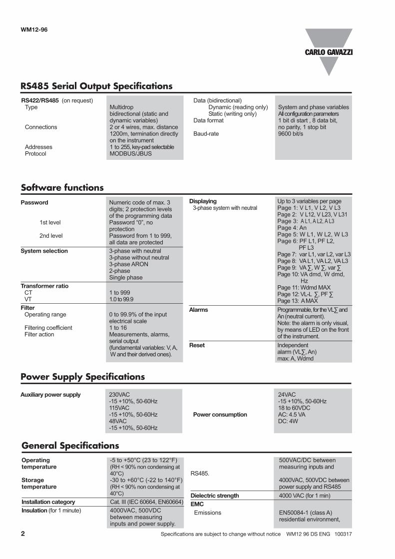
Data (bidirectional)Dynamic (reading only) System and phase variablesStatic (writing only) All configuration parameters
Data format 1 bit di start , 8 data bit, no parity, 1 stop bit
Baud-rate 9600 bit/s
RS422/RS485 (on request) Type Multidrop
bidirectional (static and dynamic variables)
Connections 2 or 4 wires, max. distance 1200m, termination directly on the instrument
Addresses 1 to 255, key-pad selectable Protocol MODBUS/JBUS
RS485 Serial Output Specifications
Displaying Up to 3 variables per page 3-phase system with neutral Page 1: V L1, V L2, V L3
Page 2: V L12, V L23, V L31 Page 3: A L1, A L2, A L3 Page 4: An Page 5: W L1, W L2, W L3 Page 6: PF L1, PF L2, PF L3 Page 7: var L1, var L2, var L3 Page 8: VA L1, VA L2, VA L3 Page 9: VA ∑, W ∑, var ∑ Page 10: VA dmd, W dmd, Hz
Page 11: Wdmd MAX Page 12: VL-L ∑, PF ∑
Page 13: A MAXAlarms Programmable, for the VL∑ and
An (neutral current). Note: the alarm is only visual, by means of LED on the front of the instrument.
Reset Independent alarm (VL∑, An) max: A, Wdmd
Password Numeric code of max. 3 digits; 2 protection levels of the programming data 1st level Password “0”, no protection2nd level Password from 1 to 999, all data are protected
System selection 3-phase with neutral 3-phase without neutral 3-phase ARON 2-phase Single phase
Transformer ratio CT 1 to 999VT 1.0 to 99.9Filter
Operating range 0 to 99.9% of the input electrical scale
Filtering coefficient 1 to 16Filter action Measurements, alarms,
serial output (fundamental variables: V, A,
W and their derived ones).
Software functions
Auxiliary power supply 230VAC -15 +10%, 50-60Hz 115VAC -15 +10%, 50-60Hz 48VAC -15 +10%, 50-60Hz
24VAC -15 +10%, 50-60Hz 18 to 60VDC
Power consumption AC: 4.5 VA DC: 4W
Power Supply Specifications
500VAC/DC between measuring inputs and
RS485. 4000VAC, 500VDC between power supply and RS485
Dielectric strength 4000 VAC (for 1 min)EMC
Emissions EN50084-1 (class A) residential environment,
Operating -5 to +50°C (23 to 122°F)temperature (RH < 90% non condensing at
40°C)Storage -30 to +60°C (-22 to 140°F)temperature (RH < 90% non condensing at
40°C)Installation category Cat. III (IEC 60664, EN60664)Insulation (for 1 minute) 4000VAC, 500VDC
between measuring inputs and power supply.
General Specifications

Specifications are subject to change without notice WM12 96 DS ENG 100317 3
WM12-96
General Specifications (cont.)
Waveform of the signals that can be measured
Figure ASine wave, undistortedFundamental content 100%Harmonic content 0%Arms = 1.1107 | A |
Figure BSine wave, indentedFundamental content 10...100%Harmonic content 0...90%Frequency spectrum: 3rd to 16th harmonicAdditional error: <1% FS
Figure CSine wave, distorted Fundamental content 70...90%Harmonic content 10...30%Frequency spectrum: 3rd to 16th harmonicAdditional error: <0.5% FS
commerce and light industry Immunity EN61000-6-2 (class A)
industrial environment.Pulse voltage (1.2/50µs) EN61000-4-5Safety standards IEC60664, EN60664Approvals CE, cULusConnections 5(6) A Screw-type
Max cable cross sect. area 2.5 mm2
Housing
Dimensions (WxHxD) 96 x 96 x 63 mmMaterial ABS
self-extinguishing: UL 94 V-0Mounting PanelProtection degree Front: IP65 (standard),
NEMA4x, NEMA12 Connections: IP20
Weight Approx. 400 g (pack. incl.)
Display variables in 3-phase systems (in a 3-phase system with neutral)No 1st variable 2nd variable 3rd variable Note1 V L1 V L2 V L3 2 V L12 V L23 V L31 Decimal point blinking on the right of the display3 A L1 A L2 A L3 4 An AL.n AL.n if neutral current alarm is active5 W L1 W L2 W L3 Decimal point blinking on the right of the display if generated power6 PF L1 PF L2 PF L3 7 VAR L1 VAR L2 VAR L3 Decimal point blinking on the right of the display if generated power8 VA L1 VA L2 VA L3 9 VA system W system VAR system 10 VA dmd W dmd Hz dmd = demand (integration time (system) (system) (system) selectable from 1 to 30 minutes)11 W dmd MAX Maximum sys power demand12 V LL system AL.U PF system AL.U= is activated only if one of VLN is not within the set limits13 A MAX max. current among the three phases
Display pages

4 Specifications are subject to change without notice WM12 96 DS ENG 100317
WM12-96
Wiring diagrams
Used calculation formulas
ARON connection3CT and 3VT connectionCT connection
Fig. 3
ARON and VT connection
NOTE: the current inputs can be connected to the lines ONLY by means of current transformers. The direct connection is notallowed.ATTENTION: Only one ammeter input can be connected to earth, as shown in the electrical diagrams.
2-phase connection
[1] [2] [3]
1-Last instrument2-1...n Instrument3-SIU-PC
4-wire connection
Fig. 4
Fig. 2Fig. 1
Fig. 5 RS485 serial connection Fig. 6
Instantaneous apparent power
Instantaneous reactive power
System variablesEquivalent 3-phase voltage
3-phase reactive power
Phase variablesInstantaneous effective voltage
Instantaneous active power
Instantaneous power factor
Instantaneous effective current
3-phase active power
3-phase apparent power
3-phase power factor
Neutral current
An = AL1 + AL2 + AL3
17 19 21 15 24 23 26 25 28 27
L1L2L3N
F1
17 19 21 15 24 23 26 25 28 27
L1L2L3N
17 19 21 24 23 26 25
L1L2L3
17 19 15 24 23 26 25
L1L2
N
F1
17 15 24 23
L1L2L3N
F1
F1= 315mA

Specifications are subject to change without notice WM12 96 DS ENG 100317 5
WM12-96
1. Key-pad To program the configuration parameters and the display of the variables.
Key to enter programming and confirm selections;
Keys to: - programme values; - select functions; - display measuring pages.
2. DisplayLED-type with alphanumeric indications to:
- display configuration parameters; - display all the measured variables.
▲▲
S
Front Panel Description
1
2
Dimensions and Panel Cut-out
96mm
91mm
61.4mm15.4mm
96m
m
96m
m