Embed Size (px)
Citation preview
Page 256
Energy-Efficient Resource Allocation in OFDMA Systems with
Large Numbers of Base Station Antennas
N. Pavan Kumar
Assistant Professor
Department of ECE
Vignan Institute of Technology & Science.
INTRODUCTION
Wireless technologies have evolved remarkably since
Guglielmo Marconi first demonstrated radio's ability
to provide continuous contact with ships sailing in the
English Channel in 1897. New theories and
applications of wireless technologies have been
developed by hundreds and thousands of scientists and
engineers through the world ever since. Wireless
communications can be regarded as the most
important development that has an extremely wide
range of applications from TV remote control and
cordless phones to cellular phones and satellite-based
TV systems. It changed people's life style in every
aspect. Especially during the last decade, the mobile
radio communications industry has grown by an
exponentially increasing rate, fueled by the digital and
RF (radio frequency) circuits design, fabrication and
integration techniques and more computing power in
chips. This trend will continue with an even greater
pace in the near future. The advances and
developments in the technique field have partially
helped to realize our dreams on fast and reliable
communicating “any time anywhere”. But we are
expecting to have more experience in this wireless
world such as wireless Internet surfing and interactive
multimedia messaging so on. One natural question is:
how can we put high-rate data streams over radio links
to satisfy our needs? New wireless broadband access
techniques are anticipated to answer this question.
For example, the coming generation cellular
technology can provide us with up to 2Mbps (bits per
second) data service. But that still does not meet the
data rate required by multimedia media
communications like HDTV (high-definition
television) and video conference.
Recently MIMO systems have gained considerable
attentions from the leading industry companies and the
active academic community. A collection of problems
including channel measurements and modeling,
channel estimation, synchronization, IQ (in phase-
quadrature) imbalance and PAPR (peak-to-average
power ratio) have been widely studied. High
transmission data rate, spectral efficiency, and
reliability are necessary for wireless communications
systems.
Unlike Gaussian channels, wireless channels suffer
from attenuation due to multipath in the channel.
Multiple copies of a single transmission arrive at the
receiver at slightly different times. Without diversity
techniques, severe attenuation makes it difficult for
the receiver to determine the transmitted signal.
Diversity techniques provide potentially less-
attenuated replica(s) of the transmitted signal at the
receiver.
Multiple-Input Multiple-Output (MIMO) antenna
systems are a form of spatial diversity. In a multipath-
rich wireless channel, deploying multiple antennas, at
both the transmitter and receiver, achieves high data
rate without increasing the total transmission power or
bandwidth. Additionally, the use of multiple antennas
at both the transmitter and receiver provides
significant increase in capacity. When perfect channel
knowledge is available at the receiver, the capacity has
been shown to grow linearly with the number of
antennas. Most MIMO detection schemes are based on

Page 257
perfect channel knowledge being available at the
receiver.
Nowadays, next generation mobile communication
systems have became popular all around the world.
However, its services cannot provide a very big
dynamic range of data rates, nor can it meet the
requirements of a variety of business types. Besides,
voice transportation in 4G still relies on circuit
switching technology, which is the same method as
used in second-generation (2G) communication
systems, rather than pure Internet Protocol (IP)
approach. Thus, based on consideration listed above,
many countries have already carried out research on
the next completely evolutionary fourth generation
(4G) communication systems which provide a
comprehensive and secure IP solution where voice,
data, and multimedia can be offered to users at
"anytime, anywhere" with higher data rates than
previous generations [1]. Multiple input multiple
output (MIMO) and orthogonal frequency division
multiplexing (OF- DM) have therefore been adopted
due to their superior performance. They promise to
become key high-speed wireless communication
technologies and combining them can provide
wireless industry evolution from 4G to 5G system.
Most of the wireless communication systems are
designed to support large number subcarriers, offer
high data rates and to ensure the fulfillments of quality
of service (QoS) requirements, under the constraint
frequency spectrum and limited number of channels.
Multiple-input multiple-output (MIMO) technology
provides extra degrees of freedom which facilitate
multiplexing gains and diversity gains. It can be
shown that the ergodic capacity of a MIMO fading
channel increases practically linearly with the
minimum of the number of transmit and receive
antennas. Hence, it is not surprising that MIMO has
attracted a lot of research interest in the past decade
since it enables significant performance enhancement
without requiring additional transmit power and
bandwidth resources. However, the complexity of
MIMO receivers limits the gains that can be achieved
in practice, especially for handheld devices. An
alternative is multiuser MIMO where a transmitter
with a large number of antennas serves multiple single
antenna users. In the authors investigated the uplink
sum capacity (bit-per-second-per-Hertz) of cellular
networks assuming unlimited numbers of antennas at
both the base station (BS) and the users. In high
throughputs for both the uplink and the downlink were
shown for a time-division du- plex multi-cell system
which employed multiple BSs equipped with large
numbers of antennas. In substantial capacity gains and
better interference management capabilities were
observed for MIMO, compared to single antenna
systems.
OVERVIEW OF OFDM
OFDM is becoming a very popular multicarrier
modulation technique for transmission of signals over
wireless channels. It converts a frequency-selective
fading channel into a collection of parallel flat fading
subchannels, which greatly simplifies the structure of
the receiver.
The time domain waveform of the subcarriers are
orthogonal (subchannel and subcarrier will be used
interchangeably hereinafter), yet the signal spectral
corresponding to different subcarriers overlap in
frequency domain.
Hence, the available bandwidth is utilized very
efficiently in OFDM systems without causing the ICI
(inter-carrier interference). By combining multiple
low-data-rate subcarriers, OFDM systems can provide
a composite high-data-rate with a long symbol
duration. That helps to eliminate the ISI (inter-symbol
interference), which often occurs along with signals of
a short symbol duration in a multipath channel.
Simply speaking, we can list its pros and cons as
follows
Advantage of OFDM systems are:
High spectral efficiency;

Page 258
Simple implementation by FFT (fast Fourier
transform);
Low receiver complexity;
Robustability for high-data-rate transmission
over multipath fading channel
High flexibility in terms of link adaptation;
Low complexity multiple access schemes such
as orthogonal frequency division multiple
access.
Disadvantages of OFDM systems are:
Sensitive to frequency offsets, timing errors
and phase noise;
Relatively higher peak-to-average power ratio
compared to single carrier system, which
tends to reduce the power efficiency of the RF
amplifier.
OFDM System Model:
The OFDM technology is widely used in two types of
working environments, i.e., a wired environment and a
wireless environment. When used to transmit signals
through wires like twisted wire pairs and coaxial
cables, it is usually called as DMT (digital multi-tone).
For instance, DMT is the core technology for all the
xDSL (digital subscriber lines) systems which provide
high-speed data service via existing telephone
networks.
However, in a wireless environment such as radio
broadcasting system and WLAN (wireless local area
network), it is referred to as OFDM. Since we aim at
performance enhancement for wireless
communication systems, we use the term OFDM
throughout this thesis. Furthermore, we only use the
term MIMO-OFDM while explicitly addressing the
OFDM systems combined with multiple antennas at
both ends of a wireless link.
The history of OFDM can all the way date back to the
mid 1960s, when Chang published a paper on the
synthesis of band limited orthogonal signals for
multichannel data transmission. He presented a new
principle of transmitting signals simultaneously over a
band limited channel without the ICI and the ISI.
Right after Chang's publication of his paper, Saltzburg
demonstrated the performance of the efficient parallel
data transmission systems in 1967, where he
concluded that \the strategy of designing an efficient
parallel system should concentrate on reducing
crosstalk between adjacent channels than on
perfecting the individual channels themselves". His
conclusion has been proven far-sighted today in the
digital baseband signal processing to battle the ICI.
Figure 2.2 : OFDM Model used for simulations
Serial to Parallel Conversion:
The input serial data stream is formatted into the word
size required for transmission, e.g. 2 bits/word for
QPSK, and shifted into a parallel format. The data is
then transmitted in parallel by assigning each data
word to one carrier in the transmission.
Modulation of Data:
The data to be transmitted on each carrier is then
differential encoded with previous symbols, then
mapped into a Phase Shift Keying (PSK) format.
Since differential encoding requires an initial phase
reference an extra symbol is added at the start for this
purpose. The data on each symbol is then mapped to a
phase angle based on the modulation method. For
example, for QPSK the phase angles used are 0, 90,
180, and 270 degrees. The use of phase shift keying
produces a constant amplitude signal and was chosen
Page 259
for its simplicity and to reduce problems with
amplitude fluctuations due to fading.
Inverse Fourier Transform:
After the required spectrum is worked out, an inverse
fourier transform is used to find the corresponding
time waveform. The guard period is then added to the
start of each symbol.
Guard Period:
The guard period used was made up of two sections.
Half of the guard period time is a zero amplitude
transmission. The other half of the guard period is a
cyclic extension of the symbol to be transmitted. This
was to allow for symbol timing to be easily recovered
by envelope detection. However it was found that it
was not required in any of the simulations as the
timing could be accurately determined position of the
samples.
After the guard has been added, the symbols are then
converted back to a serial time waveform. This is then
the base band signal for the OFDM transmission.
Channel:
A channel model is then applied to the transmitted
signal. The model allows for the signal to noise ratio,
multipath, and peak power clipping to be controlled.
The signal to noise ratio is set by adding a known
amount of white noise to the transmitted signal.
Multipath delay spread then added by simulating the
delay spread using an FIR filter. The length of the FIR
filter represents the maximum delay spread, while the
coefficient amplitude represents the reflected signal
magnitude.
Receiver:
The receiver basically does the reverse operation to
the transmitter. The guard period is removed. The FFT
of each symbol is then taken to find the original
transmitted spectrum. The phase angle of each
transmission carrier is then evaluated and converted
back to the data word by demodulating the received
phase. The data words are then combined back to the
same word size as the original data.
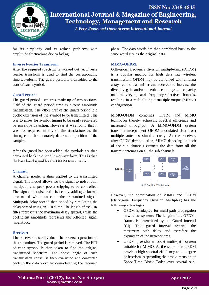
MIMO-OFDM:
Orthogonal frequency division multiplexing (OFDM)
is a popular method for high data rate wireless
transmission. OFDM may be combined with antenna
arrays at the transmitter and receiver to increase the
diversity gain and/or to enhance the system capacity
on time-varying and frequency-selective channels,
resulting in a multiple-input multiple-output (MIMO)
configuration.
MIMO-OFDM combines OFDM and MIMO
techniques thereby achieving spectral efficiency and
increased throughput. A MIMO-OFDM system
transmits independent OFDM modulated data from
multiple antennas simultaneously. At the receiver,
after OFDM demodulation, MIMO decoding on each
of the sub channels extracts the data from all the
transmit antennas on all the sub channels.
However, the combination of MIMO and OFDM
(Orthogonal Frequency Division Multiplex) has the
following advantages.
OFDM is adapted for multi-path propagation
in wireless systems. The length of the OFDM-
frames is determined by the Guard Interval
(GI). This guard Interval restricts the
maximum path delay and therefore the
expansion of the network area.
OFDM provides a robust multi-path system
suitable for MIMO. At the same time OFDM
provides high spectral efficiency and a degree
of freedom in spreading the time dimension of
Space-Time Block Codes over several sub-

Page 260
carriers. This results in a stronger system
based on the principle described previously.
ANTENNA BASICS
An antenna is a metallic object which acts as a
medium for receiving and transmitting
electromagnetic energy. It acts as a transitional
structure between the transceivers and the free space.
Officially the Institute of Electrical and Electronics
Engineers (IEEE) defines an antenna as “The part of
a transmitting or receiving system that is designed
to radiate or receives electromagnetic waves”. By
moving electrons in the antenna, electromagnetic
waves are formed. The antenna is connected to a
transmitter which is designed to output current as a
function of time. This current is an electromotive force
(EMF) which forces free charge in the conductive
element of the antenna to travel back and forth along
the transmitting antenna. In the receiving antenna,
there is free charge in the conductive element. They
are affected by the movement of charge in the
transmitting antenna. As there is usually a long
distance between the transmitting antenna and the
receiving antenna, that movement of charge in the
receiving antenna is much smaller than the quantity of
charge and movement in the transmitting antenna.
This small and somewhat distorted signal is then
amplified by the receivers. In order to understand the
basic antenna principle, there are some parameters
which have been taken into account. The basic
antenna parameters include radiation pattern, antenna
efficiency, bandwidth, directivity and antenna gain.
Radiation Pattern
An antenna radiation pattern is the angular distribution
of the power dissipated by the antenna. It is a
graphical explanation of the relative field strength
transmitted and received by an antenna. As an antenna
radiates through open space, several graphs are
sometimes needed to describe the characteristics of an
antenna. The graphs can be drawn using Cartesian
(rectangular) coordinates or a polar plot. The radiation
pattern of a half-wave dipole antenna is shown in
figure 1.
Figure 1: Radiation pattern of half-wave dipole
antenna
Antenna Efficiency
The ratio of the total radiated power to the total input
power is the antenna efficiency. The total radiated
power is the measure of how much power is radiated
by an antenna while it is connected to a transmitter.
Most of the power from a high efficiency antenna is
radiated away while a low efficiency antenna has most
of the power absorbed as losses within the antenna or
reflected away due to impedance mismatch. The
antenna efficiency can be described by the following
equation:
∈𝐑=𝐏𝐫𝐚𝐝𝐢𝐚𝐭𝐞𝐝
𝐏𝐢𝐧𝐩𝐮𝐭
Where, ∈𝐑is the antennas radiation
efficiency, Pradiated is the radiated power and, Pinput is
the input power. Efficiency is a ratio which is often
described as a percentage. It is quoted in decibels
(dB).
Bandwidth
Bandwidth is the range of frequencies in which the
antenna remains effective. According to IEEE,
bandwidth is “the range of frequencies within which
the performance of the antenna, with respect to some
characteristic, conforms to a specified standard".
Bandwidth is a key factor upon choosing the right

Page 261
antenna. For instance, antennas with narrow
bandwidths cannot be used for wide band operations.
Bandwidth is typically quoted in VSWR (Voltage
Standing Wave Ratio).
For example, an antenna may be described as
operating at 100-400 MHz with a VSWR<1.5. This
statement implies that the reflection coefficient is less
than 0.2 across the quoted frequency range. Hence, of
the power delivered to the antenna, only 4% of the
power is reflected back to the transmitter.
Directivity
A commonly used parameter to measure the overall
ability of an antenna to direct radiated power in a
given direction is directive gain. The maximum
directive gain of an antenna is called the directivity of
the antenna. It is the ratio of the maximum radiation
intensity to the average radiation intensity. Then the
formula for directivity (D) can be written as
𝐃 =𝟒𝛑 𝐄𝐦𝐚𝐱
𝟐
𝐄 𝛉,∅ 𝟐 𝐬𝐢𝐧𝛉𝐝𝛉𝐝∅𝛑
𝟎
𝟐𝛑
𝟎
Where, “E” is the electric field intensity.
MULTIPLE ANTENNA TECHNIQUES
Traditionally, wireless communications mainly
focused on voice and smaller data transfers, whereas
most high-rate data transfer products were using wired
communications. In recent years, however, there has
been a dramatic boost in wireless multimedia
applications, such as cell phones having an integrated
camera, emailing capability and GPS. As a result, the
focus has now shifted towards wireless high speed
data transfers which traditional antennas are not
capable of delivering because of multipath and co-
channel interference. Apart from the needs of high
speed data transfers, there is also an issue of quality
control, which includes low error rate and high
capacity.
In order to maintain certain Quality of Service (QoS),
multipath fading effect has to be dealt with. As the
transmitted signal is reflected onto various objects on
its way to the receiver, the signal is faded and
distorted. This phenomenon is called multipath fading.
Co-channel interference refers to the interference
caused by different signals using the same frequency.
Hence as an alternative, multiple antennas can be used
to reduce the error rate as well as, improve the quality
and capacity of a wireless transmission by directing
the radiation only to the intended direction and
adjusting the radiation according to the traffic
condition and signal environment. All multiple
antennas are equipped with several antennas either in
the transmitter or the receiver or both of them. A
sophisticated signal processor and coding technology
is the key factor in multiple antennas. Multiple
antenna technique can be broken down into three
categories, Spatial Diversity (SD), Spatial
Multiplexing (SM) and Adaptive Antenna System
(AAS).
Spatial Diversity (SD)
Spatial diversity is a part of antenna diversity
techniques in which multiple antennas are used to
improve the quality and reliability of a wireless link.
Usually in densely populated areas, there is no clear
Line of Sight (LoS) between the transmitter and
receiver. As a result, multipath fading effect occurs on
the transmission path. In spatial diversity several
receive and transmit Antennas are placed at a distance
from each other. Thus if one antenna experiences a
fade, another one will have a LoS or a clear signal.
Figure 6 shows the basic principle of Spatial
Diversity.
Figure 6: Spatial diversity

Page 262
The same signal is fed through a single antenna or
multiple antennas, and the same signal is captured by
a single antenna or multiple antennas. In figure 6
several antennas are placed in a distance from each
other. There are various obstacles on the signal’s path.
In the case of base stations in a macro cellular
environment, with large cells with high antennas, a
distance up to 10 wavelengths is needed to ensure a
low mutual fading correlation. However, in case of
handheld devices, because of lack of space, half a
wavelength is enough for the expected result. The
reason behind this space is usually in the macro/cell
scenario, the fading of which is caused by multipath
correlations that have occurred in the near zone of the
terminal. Therefore, from the terminal side, different
paths arrive in a much wider angle, thus requiring
smaller distances, whereas from the transmitter side,
the path angle is relatively slow. That is why a larger
distance is required. Recognized spatial diversity
techniques involving multiple transmit antennas are,
for example, Alamouti’s transmit diversity scheme as
well as space-time trellis codes invented by Tarokh,
Seshadri, and Calderbank. For systems in which
multiple antennas are available only at the receiver,
there is well-established linear diversity combining
techniques dating back to the 1950’s.
Spatial Multiplexing
Multiple antenna systems are capable of establishing
parallel data streams through different antennas. This
is done in order to increase the data transfer rate. This
process is called spatial multiplexing. The bit stream
to be transmitted is divided or de-multiplexed into
several data segments. These segments are then
transmitted through different antennas simultaneously.
As several antennas are in use, bit rate increases
dramatically without the requirement of extra
bandwidth or extra transmission power. The signal
captured by the receiving antenna is a mixture of all
individual segments. They are separated at the
receiver using an interference cancellation algorithm.
A well-known multiplexing scheme was developed by
Bell Labs, known as BLAST.
Antenna Array
Single element antennas are not always sufficient for
required antenna gain and radiation pattern.
Combining several single element antennas into an
array provides a much better solution. When multiple
active antennas are joined together to a common
source in order to achieve a directive radiation pattern,
this is called an antenna array. Each individual
antenna is known as the element of an array antenna.
The radiation pattern from the array in a linear
medium is determined by vector addition of the
components of the electromagnetic fields radiated
from the individual antennas or elements. This process
is also known as the principle of superposition.
Antenna arrays can be one, two or three dimensional.
A typical array antenna is shown is figure 7.
Figure 7: A typical array antenna
There are several different configurations available for
array antennas. If the elements are arranged in a
straight line, then it is called linear array. If they are
arranged parallel to each other, then a plane array in
two dimensions is made. An array is linear when all
the elements are placed at a constant distance. The
array is called uniform when current of the same
magnitude is fed into the array. A broadside array is
formed when all the current fed into the arrays are of
the same time-phase. There are some key elements
otherwise known as array factors that are responsible
for the shaping of the radiation pattern of an antenna
array.

Page 263
MULTIPLE-INPUT MULTIPLE-OUTPUT
Multiple-Input Multiple-Output (MIMO) uses
multiple antennas on both the transmitter and receiver.
They have dual capability of combining the SIMO and
MISO technologies. They can also increase capacity
by using Spatial Multiplexing (SM). The MIMO
method has some clear advantages over Single-input
Single-output (SISO) methods. The fading is greatly
eliminated by spatial diversity; low power is required
compared to other techniques in MIMO.
Basic Building Block
A basic building block of the MIMO system is
presented in figure.
Figure :Buildingblocks of MIMO
In the figure, x and y represents transmit and received
signal vectors respectively. At first, the information to
be transmitted Is encoded and interleaved. The symbol
mapper maps the encoded information to data
symbols. These data symbols are then fed into a space-
time encoder which creates some spatial data streams.
The data streams are then transmitted by different
antennas. The transmitted signals propagate through
channels and are received by receiving arrays. The
receiver then collects all the data from the antennas
and reverses the operation to decode the data using a
space-time processor, space time decoder, symbol de-
mapper and at last the decoder.
Forms of MIMO
The Multiple Input multiple Output (MIMO) method
can be divided into various forms depending on uses.
MIMO is basically the combination of all the multiple
antenna techniques such has SISO, SIMO and MISO.
It can use the beam forming or the spatial
Multiplexing methods. MIMO can be categorized into
two types, multi-antenna types and multi-user types.
Multi-antenna types are listed below:
SISO (Single-input Single-output)
SIMO (Single-input Multiple-output)
MISO (Multiple-input Single-output)
MIMO (Multiple-input Multiple-output)
MIMO Transmitter and Receiver Structure
A basic two chain MIMO transmitter is shownin
figure.
Figure : MIMO transmitter diagram
A few explanations of the transmitter diagram are
given below:
Scrambler: The scrambler replaces the zeros and ones
in the data.
Encoder Parser: De-multiplexes the scrambled bits
and encodes them, among the number of FEC
(Forward Error Correction) encoders.
FEC Encoder: Encrypts the data to allow error
adjustment.
Stream Parser: Splits the output of the encoders into
blocks for sending to different
interleaverandmappingdevices.Theblocksofthebitssentt
otheinterleaverare known as spatial streams.
Inter leaver: Encloses the bits of each spatial stream
to avoid long sequences of noisy bits from entering
into the FEC decoder.

Page 264
QAM (Quadrature Amplitude Modulation)
Mapping: Charts the sequence of bits in each spatial
stream to different patterns.
Uses of Multiple Antenna Techniques
Smart antenna technology can be added to any
existing antenna technology in order to improve its
performance. As an ever growing technology, multiple
antenna techniques are proved to be useful in the
following areas:
Wi-Fi (Wireless Fidelity): Small devices with in an
indoor environment generally support adaptive array
systems. The main benefits that multiple antennas
have to offer incase of Wi-Fi include range increase,
modifying interference and uniform coverage. Various
VoIP (Voice over Internet Protocol) applications can
be benefited from uniform coverage where static
Quality of service (QoS) is needed. Multiple antennas can
be implemented either in access points or in mobile
clients, as the same frequencies are always in use.
Higher data rates are a perfect solution given by smart
antennas.
MIMO CHANNEL
Multiple-Input Multiple-Output (MIMO) systems
yield vast capacity increases when the rich scattering
environment is properly exploited. When examining
the performance of MIMO systems, the MIMO
channel must be modeled properly. The MIMO
channel models used throughout this thesis are
described in this section. The primary MIMO channel
model under consideration is the quasi-static,
frequency non-selective, Rayleigh fading channel
model. Figure 25 shows a block diagram of a MIMO
system with Nt transmit antennas and Nr receive
antennas.
Figure: MIMO system block diagram
OFDM DOWNLINK NETWORK
Notation:
A complex Gaussian random variable with mean μ
and variance σ2 is denoted by CN (μ,σ2), and
means “distributed as”. In this paper the following
conventions are adopted. 0(g(x)) . if limx→∞f(x)
g(x) ≤ N
for o<N<∞ [x]+=max{o,x}, [x]ba =x,if b≤x≤a; [x]b
a =
b, if b>x. .0(g(x)) denotes the asymptotic upper
bound CN×M
is the space of all N×M matrices with
complex entries. _·_ and |·| denote the Euclidean norm
of a matrix/vector and the absolute value of a
complex-valued scalar, respectively. [·]† , [·]T, and [·]
represent the conjugate transpose, transpose, and
conjugate operations, respectively. tr(S) denotes the
trace of matrix S. _R(·) denotes the real part of a
complex number. 1(·) denotes an indicator function
which is 1 when the event is true and 0 otherwise.
Channel Model:
We consider an OFDMA network which consists of a
BS with multiple antennas and K mobile users
equipped with a single antenna. The impulse
responses of all channels are assumed to be time-
invariant (slow fading). There are nF subcarriers in
each orthogonal frequency division multiplexing
(OFDM) symbol. The downlink received symbol at
user K ∈ {1, . . . , k} on subcarrier i ∈ {1, . . . , nF} is
given by
yi,k = Pi,k lkgkhi,kT f i,kxi,k + hi,k
T f i,jxi,j Pi,jlkgksi,j
j≠k
+ zi,k
where xi,k and fi,k ∈ CNTi,k × 1 are the transmitted
data symbol and the precoding vector used by the BS
to transmit to user k on subcarrier i, respectively.
NTi ,kis the number of active antennas allocated to user
k on subcarrier i for transmission. Pi,k is the transmit
power for the link from the BS to user k in subcarrier
i. si,j ∈{0,1} is the subcarrier allocation indicator in
subcarrier i for user j. hi,k ∈ CNTi,k × 1 contains the
small scale fading coefficients between the BS and
user k on subcarrier i. lkand gk represent the path loss

Page 265
and the shadowing between the BS and user k,
respectively. zi,k is the additive white Gaussian noise
(AWGN) in subcarrier i at user k with distribution
CN(0,N0), where N0 is the noise power spectral
density
Channel State Information:
In the following, since path loss and shadowing are
slowly varying random processes which both change
on the order of seconds for low mobility users, we
assume that the path loss and shadowing coefficients
can be estimated perfectly. For the multipath fading,
we assume that the users can obtain perfect estimates
of the BS-to-user fading gains hi,kT f i,k ∈ C1×1, i∈{1, . .
. , nF }, k∈{1, . . .,K} for signal detection purpose.
However, the corresponding CSIT, i.e., hi,k ∈
CNTi,k × 1 may be outdated/inaccurate at the BS
because of the mobility ofthe users or errors in uplink
channel estimation. To capture this effect, we model
the multipath fading CSIT of the link between the BS
and user k on subcarrier i as
hi,k = h i,k +∆ hi,k
where h i,k and ∆ hi,k denote the estimated CSIT vector
and the CSIT error vector, respectively. h i,k and
∆ hi,kare Gaussian random vectors and each vector has
independent elements with respect to user index k.
Besides, the elements of vectors hi,k, h i,k and ∆ hi,k
have zero means and normalized variances of 1, 1−σe2
and σe2, respectively. Assuming a minimum mean
square error (MMSE) estimator, the CSIT error vector
and the actual CSIT vector are mutually uncorrelated.
However, the fading gains of a given user may be
correlated across different subcarriers.
SIMULATION RESULTS
Outage capacity Vs Transmit Power:
Below figure shows the simulation results for the
outage capacity of the MIMO system with respective
to the transmit power. As discussed in above sections
the outage capacity or carrying capacity of the MIMO
system increases only when the number of active
antennas increases and which is indirectly need to
higher power requirements. Whenever the transmit
power increases then correspondingly the outage
capacity of the system increases. Here we have to
remember that, the meaning of increasing the transmit
power is indirectly increasing the active antennas.
In figure, whenever the transmitting and receiving
antennas both are 2 then their required transmitting
power is small and therefore their corresponding
outage capacity is also less. And in other hand
whenever the transmitting and receiving antennas both
are increased to 4 then automatically the transmitting
power also increased and the total outage capacity of
the system increases gradually as shown in figure 3.
Thus the simulation results for Outage capacity Vs
Transmit Power shows a clear description among the
capacity of the MIMO system, Transmit power
requirement and number of active antennas.

Page 266
From the simulation results of our proposed method it
is clear that the objectives our project achieves
successfully. From the above simulation results, the
energy efficiency of the MIMO system good for high
amount of power transmission, compared to less
power transmission system under equal iterations i.e.
from our discussions at equal number of iteration the
MIMO system which has more number of active
achieves high energy efficiency than with less antenna
MIMO system ender available unique power resource
only
CONCLUSION
From the above simulation results, the energy
efficiency of the MIMO system good for high amount
of power transmission, compared to less power
transmission system under equal iterations i.e. from
our discussions at equal number of iteration the
MIMO system which has more number of active
achieves high energy efficiency than with less antenna
MIMO system ender available unique power resource
only. The use of a large number of antennas is always
beneficial for the system outage capacity, even if the
CSIT is imperfect. However, an exceedingly large
number of antennas may not be a cost effective
solution for improving the system performance, at
least not from an energy efficiency point of view.
In simple words, by efficiently allocating the power
among all the active antennas and by gradually
increasing the outage capacity using proposed iterative
scheme the energy efficiency of the OFDMA system
increased which is our “An Efficient Resource
Allocation in MIMO-OFDMA Networks”.
REFERENCES
[1] D. Tse and P. Viswanath, Fundamentals of
Wireless Communication, 1st edition. Cambridge
University Press, 2005.
[2] V. K. N. Lau and Y. K. Kwok, Channel
Adaptation Technologies and Cross Layer Design for
Wireless Systems with Multiple Antennas- Theory
and Applications, 1st edition. Wiley John Proakis
Telecom Series, 2005.
[3] D. Aktas, M. Bacha, J. Evans, and S. Hanly,
“Scaling results on the sum capacity of cellular
networks with MIMO links,” IEEE Trans. Inf. Theory,
vol. 52, pp. 3264–3274, 2006.
[4] T. Marzetta, “Noncooperative cellular
wireless with unlimited numbers of base station
antennas,” IEEE Trans. Wireless Commun., vol. 9, pp.
3590–3600, Nov. 2010.
[5] J. Zeng and H. Minn, “A novel OFDMA
ranging method exploitingmultiuser diversity,” IEEE
Trans. Commun., vol. 58, pp. 945–955, Mar. 2010.
[6] P. Chan and R. Cheng, “Capacity
maximization for zero-forcing MIMOOFDMA
downlink systems with multiuser diversity,” IEEE
Trans. Wireless Commun., vol. 6, pp. 1880–1889,
May 2007.