Embed Size (px)
Citation preview

Answers for infrastructure.
Energy efficiency in building automation and controlApplication guidefor heating and cooling supply

2

3
Content
1 About this document ..............................................................................5 1.1 Source, literature.......................................................................................5 1.2 Trademarks ...............................................................................................5 1.3 Copyright...................................................................................................6 1.4 Quality assurance .....................................................................................6 1.5 Target readership ......................................................................................6 2 Energy efficiency fundamentals............................................................7 2.1 Factors that influence energy consumption in buildings...........................7 2.2 Building automation and control as the basis for energy-optimized
operation ...................................................................................................8 2.3 Term energy efficiency ..............................................................................9 3 Energy efficiency in building automation and control......................10 3.1 Directives, standards...............................................................................10 3.2 Principles of energy-efficient operation...................................................12 3.3 Requirements for energy-efficient control ...............................................13 3.4 Structure of optimum energy generation.................................................14 3.4.1 Heating....................................................................................................14 3.4.2 Cooling ....................................................................................................15 3.5 Demand control.......................................................................................16 3.5.1 Model for demand and supply.................................................................16 3.6 Function overview: Heating/Cooling .......................................................17 3.6.1 General ...................................................................................................17 3.6.2 Heating....................................................................................................17 3.6.3 Cooling ....................................................................................................18 4 Explanation of energy efficiency functions .......................................19 4.1 General functions....................................................................................19 4.1.1 Scheduler ................................................................................................19 4.1.2 Operating modes and setpoints ..............................................................20 4.2 Heating supply ........................................................................................22 4.2.1 Outside air temperature dependent supply temperature control ............22 4.2.2 Reduce supply temperature....................................................................24 4.2.3 Heating limit switch .................................................................................25 4.2.4 Night setback/quick setback ...................................................................27 4.2.5 Switch-on/switch-off optimization (OSSC) ..............................................28 4.2.6 Individual room control using thermostatic valves ..................................30 4.2.7 Individual room control with electronic controller ....................................32 4.2.8 Integrated individual room control with demand control .........................34 4.2.9 Heating demand signal ...........................................................................36 4.2.10 Differential pressure pump control ..........................................................37 4.2.11 Predictive heating control........................................................................39 4.2.12 Control of TABS ......................................................................................42 4.2.13 Generator temperature control by outside air temperature ....................44 4.2.14 Generator temperature control based on load........................................45 4.2.15 Operational sequence control of various generators based on load ......46 4.2.16 Operational sequence control of various generators based on load and
generator capacities................................................................................48

4
4.2.17 Operational sequence control of various generators based on generator efficiency .................................................................................................50
4.2.18 Monitor flue gas temperature ..................................................................52 4.2.19 Charging control for domestic hot water .................................................53 4.2.20 Circulation pump control .........................................................................54 4.3 Cooling supply.........................................................................................55 4.3.1 Outside air temperature dependent supply temperature control ............55 4.3.2 Switch-on/switch-off optimization (OSSC) ..............................................57 4.3.3 Individual room control with electronic controller ....................................59 4.3.4 Integrated individual room control with demand control .........................61 4.3.5 Cooling demand signal............................................................................63 4.3.6 Differential pressure pump control ..........................................................64 4.3.7 Control of TABS.......................................................................................66 4.3.8 Interlock of heating and cooling-side control...........................................68 4.3.9 Generator temperature control by outside air temperature.....................69 4.3.10 Generator temperature control based on load........................................70 4.3.11 Operational sequence control of various generators based on load ......71 4.3.12 Operational sequence control of various generators based on load and
generator capacities................................................................................72 4.3.13 Operational sequence control of various generators based on generator
efficiency .................................................................................................74

5
1 About this document
1.1 Source, literature
The content of this manual is based on a description of principles at Siemens Building Technologies, applicable standards and directives and supplemental technical literature.
1.2 Trademarks
The table below lists the third-party trademarks used in this document and their legal owners. The use of trademarks is subject to international and domestic provisions of the law. Trademarks Legal owner BACnet American National Standard (ANSI/ASHRAE 135-
1995) KNX® KNX Association, B - 1831 Brussels-Diegem Belgium
http://www.konnex.org/ LonLink™ LON® / LonManager® LonMark® LonTalk® LonWorks®
Echelon Corporation
Microsoft … Microsoft Corporation; see http://www.microsoft.com/TRADEMARKS/t-mark/nopermit.htm
MODBUS® The Modbus Organization, Hopkinton, MA, USA Neuron® Echelon Corporation Windows Microsoft Corporation
All product names listed in the table are registered (®) or not registered (™) trademarks of the owner listed in the table. We forgo the labeling (e.g. using the symbols ® and ™) of trademarks for the purposes of legibility based on the reference in this section.

6
1.3 Copyright
This document may be duplicated and distributed only with the express permission of Siemens, and may only be passed on to authorized persons or companies with the required technical knowledge.
1.4 Quality assurance
This document was prepared with great care. The contents of all documents are checked at regular intervals. All necessary corrections are included in subsequent versions. Documents are automatically amended as a consequence of modifications and
corrections to the products described. Please make sure that you are aware of the latest document revision date. If you find any lack of clarity while using this document, or if you have any criticisms or suggestions, please contact the product manager in your nearest branch office. Addresses for Siemens RCs are available at http://www.siemens.com/buildingtechnologies.
1.5 Target readership
This guide is targeted at all persons dealing with the energy efficiency of building technical plants and who want to become familiar with the most important energy savings functions in the building automation and control system. This includes engineers of HVAC plants or measuring and control technology, installers of building technical plants, plant operators in the area of heating and cooling supply systems and persons consulting and selling building automation and control systems. This guide can serve as the basis for training in the area of energy efficiency as well as a reference book.

7
2 Energy efficiency fundamentals 2.1 Factors that influence energy consumption
in buildings The following six factors primarily impact the energy demand of a building1): Outdoor climate Building shell Building technology and energy technology Operation and maintenance of the building Building use and user behavior Interior room quality
Outside conditions
Energy consumption
Bui
ldin
g sh
ell
Bui
ldin
g an
d en
ergy
te
chno
logy
Ope
ratio
n a
nd
mai
nten
ance
Bui
ldin
g us
e an
d us
er
beha
vior
Inte
rior
room
qua
lity
Fig. 1 Energy consumption of buildings
The building shell protects the building user from the elements. The exterior shell is considered and optimized as part of the planning for new buildings. This is to some extent not possible for existing buildings (historical or protected objects) or can only be achieved at considerable effort in terms of cost and time. Energy is consumed and green house gases (CO2) are emitted in the manufacture of construction materials. Increasing a building's insulation reduces energy consumption. Energy consumption to manufacture it increases, however, which in turn increase the amount of "gray energy". In other words, increased insulation only makes sense where the reduction in energy consumption is greater than the "gray energy" of the applied materials. Building automation and control influences operation and use of building services plants thanks to clever control, monitoring and optimization functions and plays a decisive role in reducing a building's energy consumption. These measures can be implemented in the short term and are distinguished by short amortization periods.
1) according to Hiroshi Yoshino, Professor, Tohoku University, Sendai, Japan

8
2.2 Building automation and control as the basis for energy-optimized operation
The realization that careful engineering and implementation of building automation and control is the only way to achieve energy efficient building operation is increasingly gaining wider acceptance. But it is primarily the task of building automation and control to determine whether energy is applied efficiently in the building for the following areas. Building technology and energy technology Control technology matched to the building services plants and with the appropriate energy savings functions make it possible to operate the plant in an energy efficient manner. Service and maintenance Building technology requires maintenance to operate efficiently over a number of years. With monitoring, alarm and optimization functions on building automation and control systems playing an important role. Building use and user behavior The building user requires the proper operating and display elements, e.g. easy-to-understand (intuitive) operator units in the room or heating and ventilation plant operation on the panel. Allowing the user or operator to undertake the correct actions during operation. Operation matched to a building's use must be carefully engineered and implemented. User behavior plays a decisive role with regard to a building's energy consumption. Studies indicate that differences of up to 30% in consumption may occur for identically constructed buildings. A comparatively high level of consumption can occur, for example, if room temperatures are set too high or windows are left open for too long to air out rooms or, even worse, opened to lower the room temperature. Interior room quality Building technology is designed for certain room conditions including temperature, humidity, brightness, noise and air flow. Building automation and control is tasked with recording these variables and controlling the plants to ensure the conditions are met during occupancy at the lowest possible energy costs.
9
2.3 Term energy efficiency
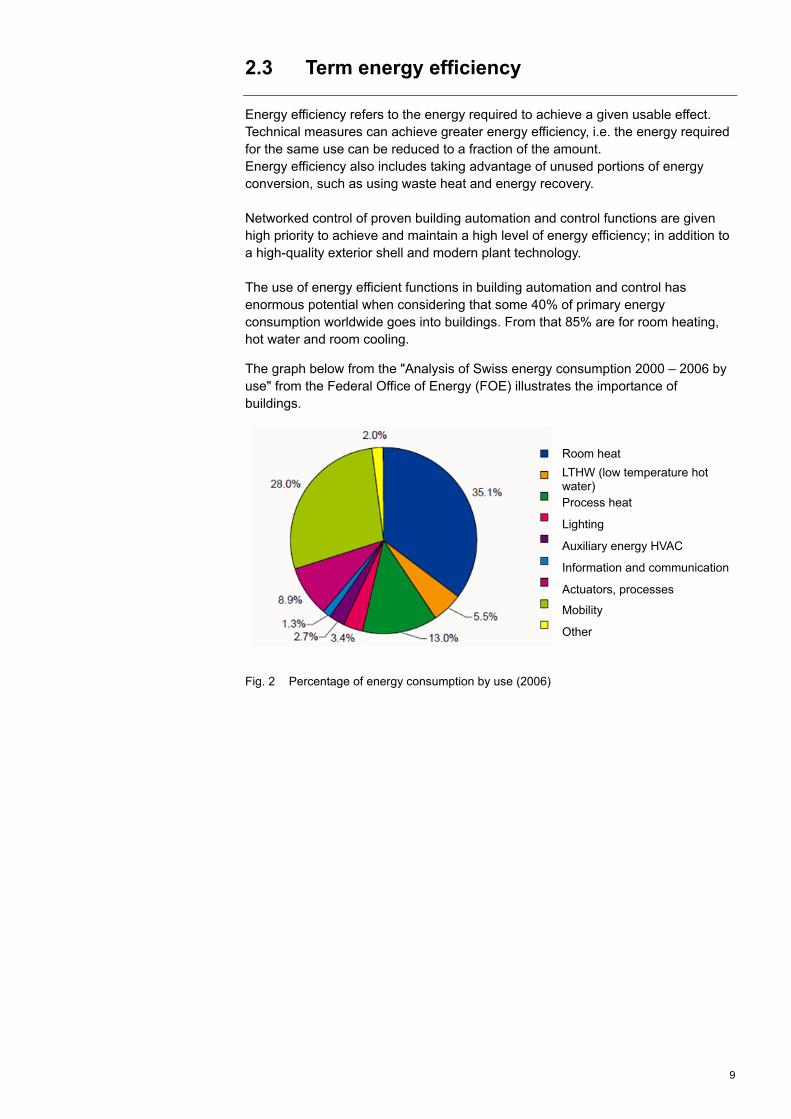
Energy efficiency refers to the energy required to achieve a given usable effect. Technical measures can achieve greater energy efficiency, i.e. the energy required for the same use can be reduced to a fraction of the amount. Energy efficiency also includes taking advantage of unused portions of energy conversion, such as using waste heat and energy recovery. Networked control of proven building automation and control functions are given high priority to achieve and maintain a high level of energy efficiency; in addition to a high-quality exterior shell and modern plant technology. The use of energy efficient functions in building automation and control has enormous potential when considering that some 40% of primary energy consumption worldwide goes into buildings. From that 85% are for room heating, hot water and room cooling.
The graph below from the "Analysis of Swiss energy consumption 2000 – 2006 by use" from the Federal Office of Energy (FOE) illustrates the importance of buildings.
Fig. 2 Percentage of energy consumption by use (2006)
Room heat
LTHW (low temperature hot water) Process heat
Lighting
Auxiliary energy HVAC
Information and communication
Actuators, processes
Mobility
Other
10
3 Energy efficiency in building automation and control
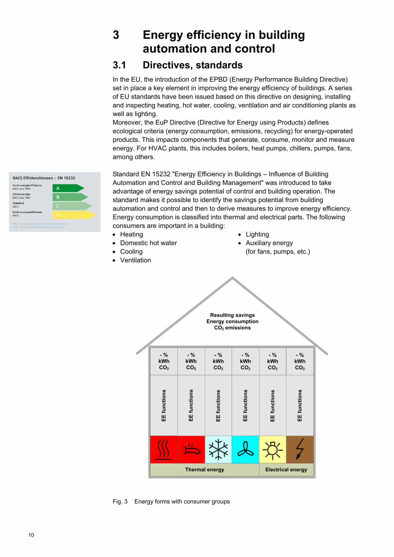
3.1 Directives, standards In the EU, the introduction of the EPBD (Energy Performance Building Directive) set in place a key element in improving the energy efficiency of buildings. A series of EU standards have been issued based on this directive on designing, installing and inspecting heating, hot water, cooling, ventilation and air conditioning plants as well as lighting. Moreover, the EuP Directive (Directive for Energy using Products) defines ecological criteria (energy consumption, emissions, recycling) for energy-operated products. This impacts components that generate, consume, monitor and measure energy. For HVAC plants, this includes boilers, heat pumps, chillers, pumps, fans, among others. Standard EN 15232 "Energy Efficiency in Buildings – Influence of Building Automation and Control and Building Management" was introduced to take advantage of energy savings potential of control and building operation. The standard makes it possible to identify the savings potential from building automation and control and then to derive measures to improve energy efficiency. Energy consumption is classified into thermal and electrical parts. The following consumers are important in a building: Heating Domestic hot water
Lighting Auxiliary energy
Cooling Ventilation
(for fans, pumps, etc.)
Fig. 3 Energy forms with consumer groups
Thermal energy Electrical energy
EE
fu
nct
ion
s
- % kWhCO2
- % kWhCO2
- % kWhCO2
- % kWhCO2
- % kWhCO2
EE
fu
nct
ion
s
- % kWhCO2
Resulting savingsEnergy consumption
CO2 emissions
EE
fu
nct
ion
s
EE
fu
nct
ion
s
EE
fu
nct
ion
s
EE
fu
nct
ion
s

11
As illustrated in Figure 3, energy efficiency (EE) functions can be used to achieve both thermal and electrical energy savings. Another consequence is a reduction in CO2 emissions. All energy consumers must be considered and optimized to minimize overall building consumption. eu.bac (european building automation and controls association) established a certification and testing process to ensure that the building automation and control products used meet high level quality and energy-efficiency criteria. The EU evaluated and approved eu.bac certification. Certifications for buildings with the labeling below are becoming increasingly more important for larger construction projects. BREEAM: Building Research Establishment’s Environmental Assessment Method http://www.breeam.org Classification using a point system with four quality levels: Pass, Good, Very Good, Excellent Issuer: Licensed assessor. LEED: Leadership in Energy and Environmental Design http://www.usgbc.org
A classification system for energy and environmentally friendly engineering of buildings using a point system with four quality levels: Certified, Silver, Gold, Platinum Issuer: Green Building Certification Institute, USA.
DGNB: Deutsches Gütesiegel Nachhaltiges Bauen (German seal of approval for sustainable construction) http://www.dgnb.de Certificate based on life-cycle principles for a building. Using a point system for gold, silver and bronze. Issuer: Deutsche Gesellschaft für nachhaltiges Bauen (German Society for Sustainable Construction). HQE: Haute Qualité Environnementable http://www.assohqe.org Distinguishes between three levels of building quality:
Base, Performant, Très performant Issuer: Association pour la Haute Qualité Environnementable
CASBEE: Comprehensive Assessment System for Building Environmental Efficiency http://www.ibec.or.jp/CASBEE/english/index.htm
Establishes "Building environmental efficiency" and considers in particular Japanese and Asian aspects: C (poor), B, B+, A (excellent) Issuer: Japan Sustainable Building Consortium.
GREEN STAR http://www.gbca.org.au Evaluation of building performance using stars: Four stars: Best, five stars: Australian Excellence,
Six stars: World Leadership. Issuer: Green Building Council of Australia.

12
3.2 Principles of energy-efficient operation
The following principles apply to operate building services plants in an energy-efficient manner:
Demand-dependent distribution and generation of energy Energy should be generated and distributed demand-dependent in only the required amount and at the appropriate temperature level.
Minimize losses at generation and in distribution networks. Proper hydraulic balancing of the plant is the prerequisite to enable optimum
energy distribution and transfer. Networking energy-efficient individual control components into one system. Shut down all plants or parts thereof if no demand is pending. Adapt operating times to occupancy. Group and provide common supply to areas with the same use or similar
behavior (building orientation with the corresponding solar radiation). Different room operating modes (Comfort, PreComfort, Economy, Protection)
and their varying setpoints allow for operation adapted to various uses. Maintain room conditions such as temperature, humidity and air quality within
comfort range during occupancy. Define an operating concept with information on room conditions, occupancy
and operating times, etc. Demand-oriented energy transfer to achieve comfortable room conditions. Transfer of energy must be unimpeded (e.g. do not cover radiators). For unintentional user interventions (e.g. ventilation losses from open windows),
energy transfer is reduced and then only released again in case safety limits are breached.
Take advantage of energy gains in the room (sun, internal loads, etc.). Visualize energy consumption and report violations of tolerance values (e.g. in
green, yellow and red). Visualize and report violations of defined tolerance levels for individual data
points (e.g. physical variables, switch-on frequencies, switch-on period). Energy reporting, trend functions to follow-on analysis, etc.

13
3.3 Requirements for energy-efficient control
It is not enough to only use the best available components to achieve a high-level of energy efficiency in a building. The components must be matched as well - technically, but also in the way they are controlled. As a rule, a building automation and control system is needed to achieve optimum interaction. Consumption can still be too high even where the subsystems are optimally matched if the subsystems are not operated to actual demand; for example, a refrigeration plant operating outside of normal occupancy or cooling storage that was unnecessarily charged, etc. The building services plant must meet the following requirements for energy-optimized operation:
High-efficient components Boiler, heat pumps, hot water heater, cooling plants, energy recovery, etc.
Optimum interaction All components feature energy-optimized design, installation, commissioning and acceptance. In this regard, lean / correctly sized (oversizing should be consciously avoided) and balanced plants are quite important.
Plant concept Designed accordingly to use and actual user demand. Separate plants into consumers that permit energy-optimized operation (forming groups by simultaneity, temperature level, etc.)
Control concepts Equipped for automated control including networking of all information carriers for demand control. Consider user behavior, take best-possible advantage of free heat including solar radiation, waste heat from people and devices (winter), prevent unnecessary cooling loads, prevent losses from integration and evaluation of appropriate messages (window contacts).
Operation Operation to actual use with continuous adaption of operation to changing demand.
Technical services/operator Trained personnel only used to take care of plants and systems.
Building automation and control must meet the following requirements for energy-optimized operation:
Decentralized functions, networked with superposed functions. Operation and monitoring (sufficient possibilities for user-friendly operation and
monitoring). Log, process, monitor and visualize relevant data (physical and virtual data
points). Etc.

14
3.4 Structure of optimum energy generation 3.4.1 Heating
The following principles illustrate the design and elements of a heating plant:
Components: Radiator, floor heating, thermally activated building systems (TABS), fan coils, heating coil, domestic hot water (DHW), control equipment, valves, hydraulic balancing valves. Components: Distribution network is properly insulated pumps, control circuit for each group, valves, hydraulic circuit depending on requirements, hydraulic balancing valves. Shutoff elements and energy measuring.
Hea
ting
gene
ratio
nH
eatin
g d
istr
ibut
ion
Hea
ting
cons
umer
s
M
Components: Boiler using various fuels, including: Oil, natural gas, wood chips, pellets; condensing boiler for oil and gas, heat pumps and geothermal plants, district heating, solar heat recovery, cogeneration plants, heat storage tanks, pumps.
Fig. 4 Principle of a heating plant
Real plants have any number of possible combinations that place high demands on hydraulic design and the control concept. Energy-efficient plants are distinguished by having components that are correctly sized, installed and commissioned. System temperatures are set as low as possible (ca. 30 °C) in modern, energy-efficient plants. This allows the use of renewable energy carriers at a high level of efficiency (e.g. heat pumps) and minimizes losses from generation and distribution. We recommend using differential pressure dependent hydraulic circuits to control flow in the piping network. A considerable amount of electrical energy can be saved from supply pumps thanks to variable water flow since plants largely operate at partial load operation. Building automation and control functions control each of the control loops in the aforementioned three areas – heating consumer, distribution and generation. The three areas must be networked to exchange the necessary information as an important prerequisite to achieve energy-efficient building automation and control.
15
3.4.2 Cooling
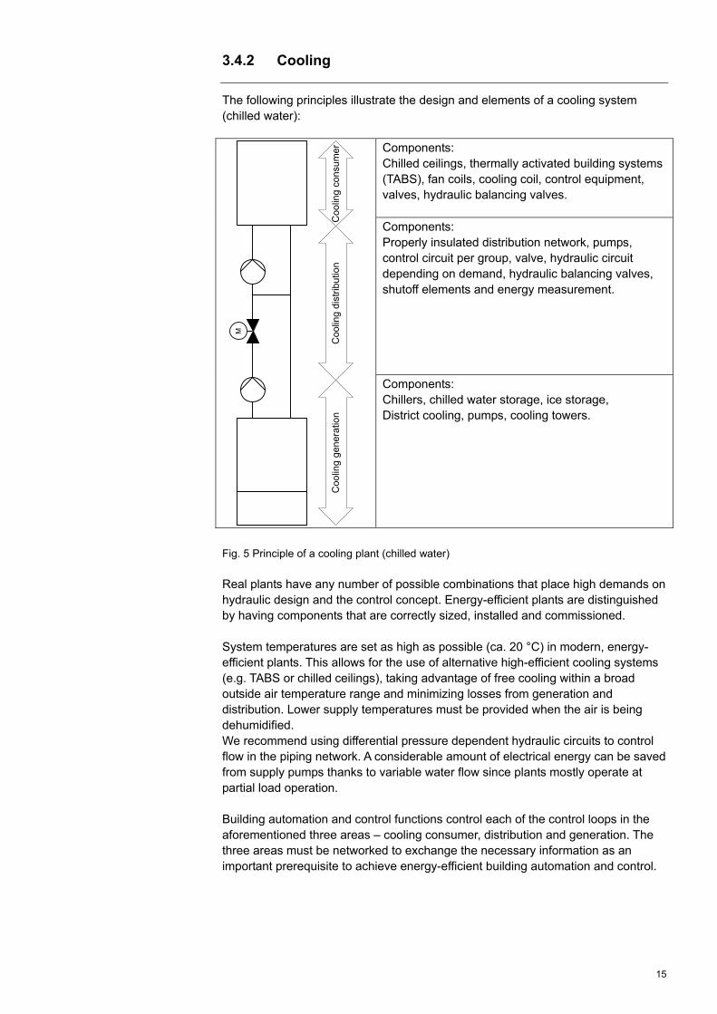
The following principles illustrate the design and elements of a cooling system (chilled water):
Components: Chilled ceilings, thermally activated building systems (TABS), fan coils, cooling coil, control equipment, valves, hydraulic balancing valves. Components: Properly insulated distribution network, pumps, control circuit per group, valve, hydraulic circuit depending on demand, hydraulic balancing valves, shutoff elements and energy measurement.
Coo
ling
gen
erat
ion
Coo
ling
dist
ribu
tion
Coo
ling
con
sum
er
M
Components: Chillers, chilled water storage, ice storage, District cooling, pumps, cooling towers.
Fig. 5 Principle of a cooling plant (chilled water)
Real plants have any number of possible combinations that place high demands on hydraulic design and the control concept. Energy-efficient plants are distinguished by having components that are correctly sized, installed and commissioned. System temperatures are set as high as possible (ca. 20 °C) in modern, energy-efficient plants. This allows for the use of alternative high-efficient cooling systems (e.g. TABS or chilled ceilings), taking advantage of free cooling within a broad outside air temperature range and minimizing losses from generation and distribution. Lower supply temperatures must be provided when the air is being dehumidified. We recommend using differential pressure dependent hydraulic circuits to control flow in the piping network. A considerable amount of electrical energy can be saved from supply pumps thanks to variable water flow since plants mostly operate at partial load operation. Building automation and control functions control each of the control loops in the aforementioned three areas – cooling consumer, distribution and generation. The three areas must be networked to exchange the necessary information as an important prerequisite to achieve energy-efficient building automation and control.

16
3.5 Demand control 3.5.1 Model for demand and supply
Supply media
Consumer
Consumer
Consumer
Consumer
Consumer
Generator
Distribution
Demand control
Energy demand signals
Rooms
Fig. 6 Energy demand and supply model
The room is the source of demand (e.g. heating and cooling demand). Suitable building services plants and matched control ensure demand-controlled, comfortable conditions in the rooms with regard to temperature, humidity, air quality and lighting. Operating times for the partial plants can be optimized when supply media is provided based on consumer demand which in turn minimizes losses in distribution and generation. Energy-efficient building automation and control functions are distinguished by optimized, individual energy-savings components from consumer to generation using networked control. Matching the components guarantees that building automation and building technology components are integrated into one energy-efficient overall system.

17
3.6 Function overview: Heating/Cooling 3.6.1 General
The superposed, generally applicable functions to operate plants in an energy-efficient manner: Scheduler. Operating modes and setpoints.
3.6.2 Heating
Consumer, room: Individual room control with thermostatic valve. Individual room control with electronic controller. Individual room control with information exchange to distribution and generation.
Presence detector. Window contact to limit heat loss in room. Close blinds as heat insulation to prevent heat loss. Maximum limitation of room temperature. Demand signal heat.
Consumer, domestic hot water: Charging control for domestic hot water. Interval operation circulation pump. Heating distribution: Heating limit switch. Differential pressure control (primary pump, group pump). Heating demand signal. Switch-on/switch-off optimization (OSSC). Night setback/quick setback. Outside air-temperature dependent supply temperature control. Reduction in supply temperature from
Room influences or solar radiation. Maximum limitation of the supply temperature.
Predictive control. TABS control. Heating generation: Heating limit switch. Generator temperature control by outside air temperature. Generator temperature control based on load. Operational sequence control of various generators based on load. Operational sequence control of various generators based on load and
generator capacities. Operational sequence control of various generators based on generator
efficiency of use..
Various: Monitor flue gas temperature.

18
3.6.3 Cooling
The following is a selection of available functions to generate and distribute cooling energy. Consumer, room: Individual room control with electronic controller. Individual room control with information exchange to distribution and generation. Presence detector.
Window contact to limit cold loss in room. Dew point monitoring. Close blinds as heat insulation to reduce heat gain from solar radiation. Room temperature setpoint shift based on outside air temperature (summer
compensation). Cooling demand signal..
Cooling distribution: Interlock heating/cooling. Outside air-temperature dependent supply temperature control. Switch-on/switch-off optimization (OSSC). Demand signal for cooling. Differential pressure control (primary pump, group pump). TABS control. Cooling generation: Generator temperature control by outside air temperature. Generator temperature control based on load. Operational sequence control of various generators based on load. Operational sequence control of various generators based on load and
generator capacities. Operational sequence control of various generators based on generator
efficiency.

19
4 Explanation of energy efficiency functions
4.1 General functions 4.1.1 Scheduler
The function is intended to Minimize operating times for plants and components and thereby lower energy
consumption. The function can be used in a number of applications to switch building technical plants. A scheduler offers functions associated with well-known time switches with the following extensions: Weekly program for seven days
for repetitive events multiple entries for various days and time windows possible
Exception day program for entries with date and time.
Calendar for data, week and/or date range entries, e.g. vacation.
Switching various outputs including single and multi-state plants Setpoints operating modes, etc.
Resolution (the smallest switching value) for the scheduler is generally one minute. Time sync and summer/winter changeover is ensured within networked controllers with system functions. The example below illustrates a two-stage output with weekly schedule that includes various exceptions.
Fig. 7 Example for a weekly scheduler Enables class C. Entry of all scheduler entries matched to occupancy. Sigmagyr, Synco, DESIGO
Target
Use
Functioning
BAC efficiency class as per EN 15232
Prerequisites
Product range

20
4.1.2 Operating modes and setpoints
The function is intended to Easily adapt setpoints and operating modes to the user's individual needs, Simplify scheduler entries. The function can be used as operational support in conjunction with plant states with the appropriate setpoints. Operator intervention, automation facility or the process determines the operating mode. Operating modes have various states and associated setpoints. The following states are available for room control: Comfort
The operating mode for an occupied room. The room state is within the comfort range with regard to temperature, humidity, air quality and movement as well as brightness and blinding.
PreComfort Is an energy-savings operating mode for a room. The room state quickly achieves the comfort range when switching to operating mode Comfort. Control operates using setpoints in PreComfort operation that may deviate from Comfort setpoints. A presence detector/key is normally used for changing over from PreComfort to Comfort, but may also take place using the scheduler.
Economy Is an energy-saving operating mode for the room where Comfort mode is not required for longer periods. Control operates using setpoints in Economy mode that may deviate from PreComfort and Comfort setpoints. A scheduler is normally use for the changeover to Economy mode.
Protection mode Is an operating mode where a plant is switched on for cool down, frost and overheat protection of a building and its facilities. An event message from a window contact or condensation monitor or scheduler may be used to changeover to Protection mode.
The following terms are typically used for hot water heating: Normal operation
In conjunction with the normal temperature setpoint for the hot water. Reduced operation
In conjunction with the reduced temperature setpoint for hot water. Protection mode
In conjunction with the setpoint for the shut down plant. Only protection functions (e.g. frost protection) remain enabled.
Not mentioned.
Target
Use
Functioning
BAC efficiency class as per EN 15232

21
The neutral zone between heating and cooling must be as large as possible. Select different setpoints for operating modes Comfort, PreComfort, and
Economy to take advantage of achievable energy savings. Sigmagyr, Synco, DESIGO
Prerequisites
Product range

22
4.2 Heating supply 4.2.1 Outside air temperature dependent supply temperature
control
The function is intended to control building zones to… Balance heat loss from heated rooms as the outside air temperature declines, Consider occupancy. The function is used in heating control for… Radiators, Convectors, Floor heating, Ceiling heating. In larger buildings, the heating circuits are divided by directions (e.g. north, south) to adapt temperature level, boost heating and setback operation.
Heating generation Heating distribution Heating consumers
M
The required heat output for a building zone is determined using the outside air temperature value for outside air temperature dependent control. A sensor attached to the building's exterior shell records outside air temperature; the required supply temperature is then calculated per this measured value. This relationship provides the so-called heating curve. You must be able to individually set the heating curve to operate the heating plant economically. The function is also referred to as weather-dependent supply temperature control Heat loss in heated rooms increases as the outside air temperature decreases. More heat must be provided to the rooms to maintain the room temperature within the comfort range. At the given radiator size, output can be changed by adapting the temperature of the heating water (supply temperature).
Outside temperature
Water temperature
0-10 2010 155-5
10
20
30
40
50
°C
Supply temperature
Return temperature
°C
Fig. 8 Heating curve
Target
Use
Effect
Functioning

23
The outside air temperature is not always the measurement for current heating energy demand. Well-insulated buildings or buildings with considerable storage mass do not need to be immediately supplied with higher supply temperatures as the outside air temperature drops. The effective outside air temperature that considers the dynamics of the exterior shell (attenuation of the influence of changes to the outside air temperature on supply temperature) takes care of the adaptation. Further considered are foreign energy sources inside that are not recorded by an outside sensor. This disadvantage can be minimized using a temperature sensor in the reference room that influences the supply temperature. Caution: A lower supply temperature is required after building insulation has been improved. In other words, the heating curve (setback) must be optimized each time insulation is added. Enables class C. Optimized heating curve, in other words, reduce the heating curve temperature
in stages until the supply temperature is just right for heating purposes. Or as flat a heating curve as possible.
Heating circuit with control valve and circulating pump. Current scheduler with information on occupancy periods and times for setback
operation (vacation, night, holidays, etc.). Sigmagyr, Synco, DESIGO
BAC efficiency class as per EN 15232
Prerequisites
Product range

24
4.2.2 Reduce supply temperature
The function is intended to Lower the supply temperature for a heating circuit by recording the room
temperature, considering solar radiation or through an adjustable maximum limitation. Reduces energy consumption due to smaller heat loss and shortened runtimes for circulating pumps.
The function can be used to control … Heating circuits, Pre-control.
Heating generation Heating distribution Heating consumers
Demand
M
The supply temperature for radiators can be reduced if the room temperature exceeds the setpoint due to internal foreign sources or solar radiation. Internal heat gains that result in an undesired increase in the room temperature, can be recorded by installing a room temperature reference sensor and then using it to reduce the supply temperature. Solar radiation can also result in impermissible increases in the room temperature. You can compensate for rooms with a heating circuit on the same side of the building by installing a solar sensor. High winds cool off the rooms even faster, especially with leaky exterior shells. A supply temperature adjustment can be calculated using a wind speed sensor to compensate for a cooling down of the room temperature. An adjustable maximum value for the supply temperature can correct wrong user entries or better meet system-related room conditions (e.g. for heat pumps). Limiting the supply temperature can result in considerable energy savings depending on system temperatures. The application reduces energy use. It lowers… Operating hours of the circulating pumps, Heat loss in the piping network. Enables class A. Heating circuit with control valve and circulating pump. Current scheduler with information on occupancy periods and times for setback
operation (vacation, night, holidays, etc.). Temperature sensor in the reference room or solar sensor or wind sensor. Sigmagyr, Synco, DESIGO
Target
Use
Effect
Functioning
BAC efficiency class as per EN 15232
Prerequisites
Product range

25
4.2.3 Heating limit switch
The function is intended to Switch off consumer groups for outside air temperatures that achieve the room
setpoint without heat output. Treat daytime and night time operation differently. The function can be used for all types of heating plants. In larger buildings, the heating circuits are divided by directions (e.g. north, south) or occupancy, to adapt individual modifications to the heating limit switch setting.
An outside air temperature value is set for the heating limit above which the heating function is locked. The present, effective and filtered outside air temperature is assessed as the criteria. The effective outside air temperature considers the dynamics of the exterior shell, whereas the filtered outside air temperature also includes the ability of the entire building to store heat. A building time constant (construction: light, medium or heavy) is used to modify the storage ability. Winter operation is enabled for heat generation if the filtered outside air temperature is below the current heat limit. The switching limits to switch on and off heating are set separately for day / night operation. The switching limit is provided with a switching differential (e.g. 1 K) to prevent unnecessary switch on and off. The present and effective outside air temperature must breach the selected limit setpoint for day / night for heat distribution to switch on. Heat distribution is, however, switched off (i.e. pump off, actuator closed) if one of the two temperatures exceeds the select limit setpoint for day or night.
Fig. 9 Enable heating limit switch
Target
Use
Effect
Functioning

26
Enables class C. (not explicitly mentioned, but indirectly included as part of outside air temperature-dependent control). Time constant building is modified. Sigmagyr, Synco, DESIGO
BAC efficiency class as per EN 15232
Prerequisites
Product range
27
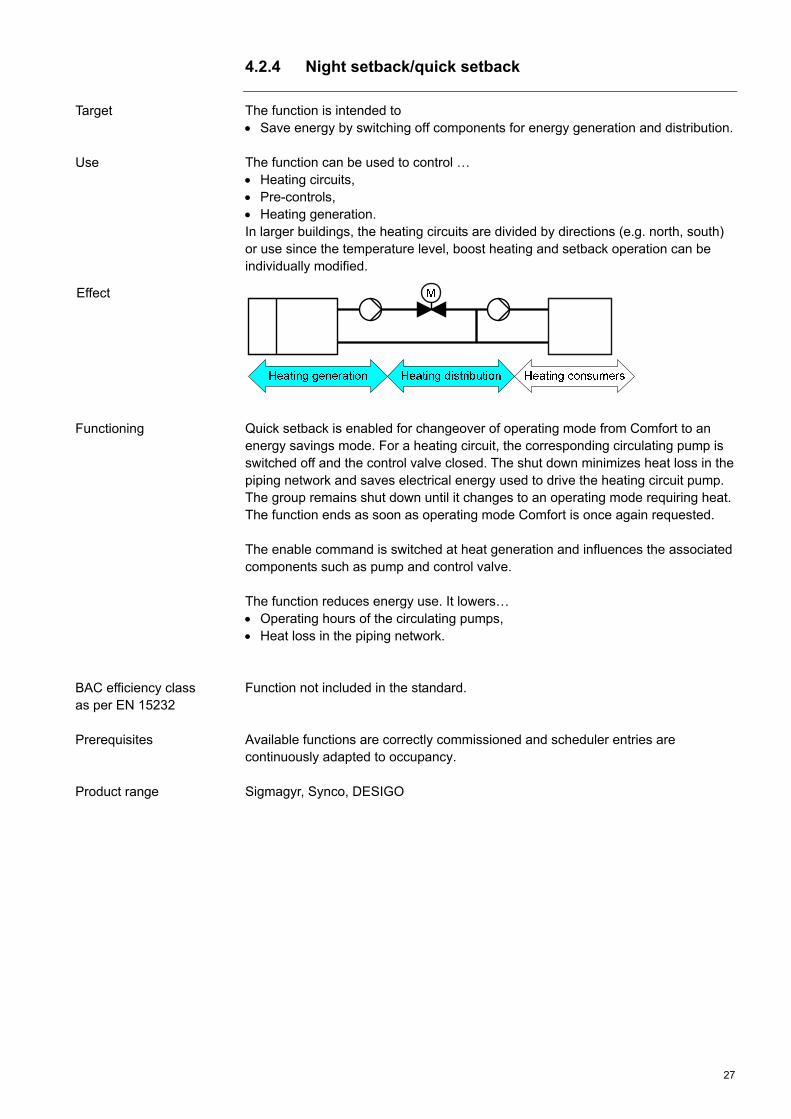
4.2.4 Night setback/quick setback
The function is intended to Save energy by switching off components for energy generation and distribution. The function can be used to control … Heating circuits, Pre-controls, Heating generation. In larger buildings, the heating circuits are divided by directions (e.g. north, south) or use since the temperature level, boost heating and setback operation can be individually modified.
Quick setback is enabled for changeover of operating mode from Comfort to an energy savings mode. For a heating circuit, the corresponding circulating pump is switched off and the control valve closed. The shut down minimizes heat loss in the piping network and saves electrical energy used to drive the heating circuit pump. The group remains shut down until it changes to an operating mode requiring heat. The function ends as soon as operating mode Comfort is once again requested. The enable command is switched at heat generation and influences the associated components such as pump and control valve. The function reduces energy use. It lowers… Operating hours of the circulating pumps, Heat loss in the piping network. Function not included in the standard. Available functions are correctly commissioned and scheduler entries are continuously adapted to occupancy. Sigmagyr, Synco, DESIGO
Target
Use
Effect
Functioning
BAC efficiency class as per EN 15232
Prerequisites
Product range
28
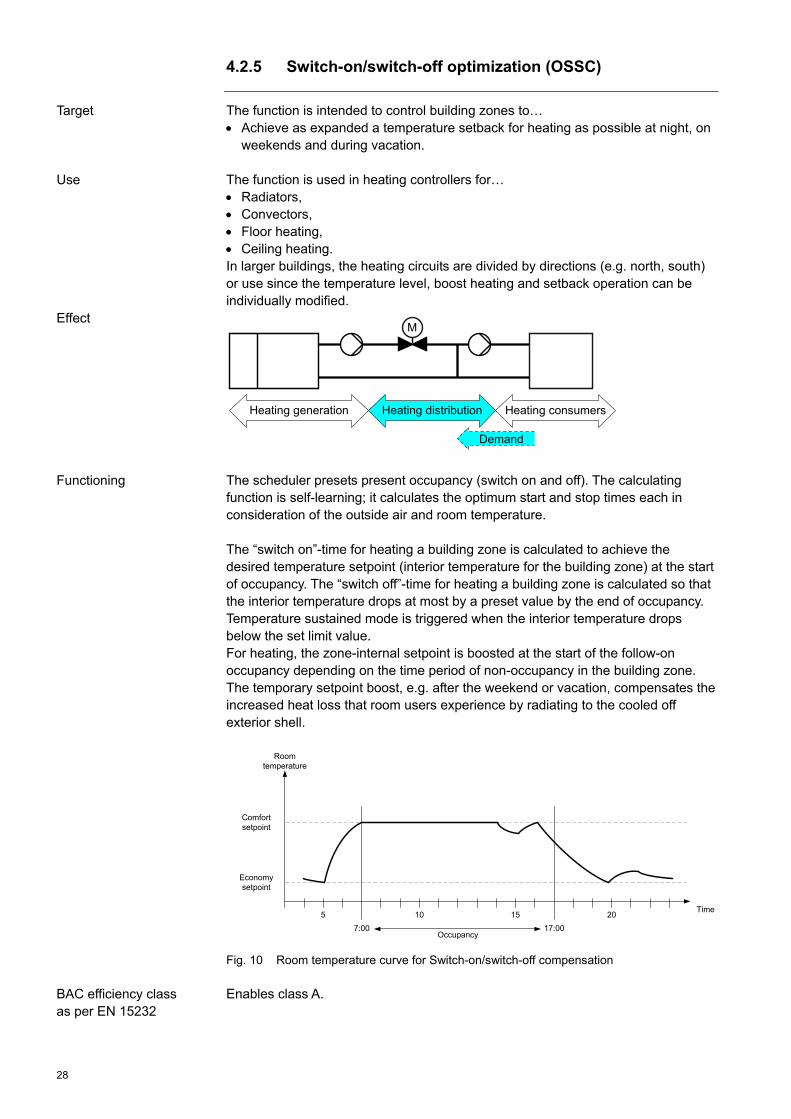
4.2.5 Switch-on/switch-off optimization (OSSC)
The function is intended to control building zones to… Achieve as expanded a temperature setback for heating as possible at night, on
weekends and during vacation. The function is used in heating controllers for… Radiators, Convectors, Floor heating, Ceiling heating. In larger buildings, the heating circuits are divided by directions (e.g. north, south) or use since the temperature level, boost heating and setback operation can be individually modified.
Heating generation Heating distribution Heating consumers
Demand
M
The scheduler presets present occupancy (switch on and off). The calculating function is self-learning; it calculates the optimum start and stop times each in consideration of the outside air and room temperature. The “switch on”-time for heating a building zone is calculated to achieve the desired temperature setpoint (interior temperature for the building zone) at the start of occupancy. The “switch off”-time for heating a building zone is calculated so that the interior temperature drops at most by a preset value by the end of occupancy. Temperature sustained mode is triggered when the interior temperature drops below the set limit value. For heating, the zone-internal setpoint is boosted at the start of the follow-on occupancy depending on the time period of non-occupancy in the building zone. The temporary setpoint boost, e.g. after the weekend or vacation, compensates the increased heat loss that room users experience by radiating to the cooled off exterior shell.
Comfort setpoint
Economysetpoint
5 10 15 20Time
7:00 17:00
Room temperature
Occupancy
Fig. 10 Room temperature curve for Switch-on/switch-off compensation
Enables class A.
Target
Use
Effect
Functioning
BAC efficiency class as per EN 15232

29
A building zone may encompass one or multiple rooms controlled by the same
plant and with the same occupancy. A reference room is selected in each building zone. Its measured interior
temperature is used as the actual value for the comfort temperature to control all the rooms belonging to this building zone. A room model may be used to calculate room temperature if no representative room temperature measurement is possible.
The hydraulic network must be balanced. The building time constant must be known. The reference room cannot be equipped with controlled valves. Sigmagyr, Synco, DESIGO
Prerequisites
Product range

30
4.2.6 Individual room control using thermostatic valves
The function is intended to Maintain the desired temperature in the room, Adapt room temperature to occupancy, Compensate for external influences. The function can be used to control … Radiators, Floor heating.
Heating generation Heating distribution Heating consumers
M
The thermostatic radiator valve is a mechanical temperature controller without auxiliary energy that supplies depending on the actual room temperature a radiator via a valve with lower or higher heating water flow to maintain a constant room temperature. The temperature sensor consists of one expansion element filled with gas or liquid. The element expands as the room temperature increases, the transfer pin presses against the valve stem. The valve closes slowly and lowers in this manner water flow. The radiator now radiates less heat. The expansion element recedes as the temperature in the room drops, the spring return opens the valve. Water flow is increased and the radiator now radiates more heat. The desired room temperature is selected by turning the thermostatic valve knob. The entire knob with expansion element and transfer pin are tightened closer to the valve housing as you turn the knob to the right. This reduces the valve opening and lowers the set room temperature. Turning the knob to the left opens the valve and increases heat transfer. The desired setting for a thermostatic radiator valve corresponds to the desired room temperature setpoint. This should only be changed if the intent is to continuously adapt the setpoint (higher or lower). Temporarily "Turning up" beyond the preset setting does not achieve boost heating, but rather overheats a room since "turning up" sets a higher setpoint temperature. The thermostatic actuator cannot be covered by radiator covers, furniture and drapes or be influenced by direct sunlight or cold air / draughts. In this case, we recommend using temperature controllers with detached sensors. A night setback of the supply temperature has the effect of opening the thermostatic radiator valves for the same setpoint setting, since the room temperature is not achieved due to the reduced supply temperature. The circulating pump must be equipped with the appropriate control to reduce heating water flow and, therefore, electricity use. The control deviation is normally at around 2 K; for higher energy-savings, optimized controllers at 1 K. The tolerance range and less than exact setting of the setpoint limits energy savings.
Target
Use
Effect
Functioning

31
Enables class C. The hydraulic network allows for the use of thermostatic radiator valves. The hydraulic network is balanced. The supply temperature should be controlled dependent on the outside air
temperature to achieve a satisfactory control response from thermostatic radiator valves.
A pressure-controlled pump needs to be installed to maintain a constant differential pressure level on the thermostatic radiator valve. Installing an overflow valve between supply and return lines to balance pressure is no longer considered state of the art.
TRV
BAC efficiency class as per EN 15232
Prerequisites
Product range

32
4.2.7 Individual room control with electronic controller
The function is intended to Maintain the desired temperature in the room, Adapt room temperature and scheduled operation to occupancy, Compensate for external influences. The function can be used to control … Radiators, Convectors, Floor heating, Ceiling heating, Electric direct heating, Fan coils.
Heating generation Heating distribution Heating consumers
DemandDemand
M
An electronic temperature controller records the actual value for the room temperature with the help of a temperature sensor; compares it to a setpoint and then controls to the desired setpoint via a positioning unit. Intervention by the temperature controller is either triggered by a change to the setpoint or change in load. For example, a change of the ambient temperature. It is referred to as disturbance variable. Each change to a disturbance variable affects a change to the controlled variable. The element that executes the comparison between actual and setpoint value and specifies the value for the positioning equipment is referred to as controller. The positioning signal to the required actuating device, consisting of an actuator and positioning unit, is wireless or via fixed wiring. The following control strategies are possible corresponding to the selected actuator: 2-point control and pulse-width modulation (PWM) (quasi-modulating). 3-point control (quasi-modulating). Modulating control. The thermostat is the most important form of a temperature controller and may have significant control deviations of up to 2 K (2-point) or small control deviations < 0.5 K (quasi-modulating and modulating) depending on the control type. In addition to control functions, electronic temperature controllers also include other functions, among others: Scheduler and calendar functions. Demand control with presence detector. Economy mode by evaluating window contacts. Operation and display. Operating modes such as:
Comfort mode, Economy mode, protection mode. Operating hours counter Communication.
Target
Use
Effect
Functioning

33
A scheduler integrated on the controller allows for time-controlled operation of a room using temperatures dependent on occupancy, such as… Setback of temperature for absences (holidays, working hours), Night setback, Comfort mode for occupancy. The function minimizes energy use. It permits… Different temperatures in separate rooms, Compensation for the influence of exterior sources of heat (sun), Compensation for the influence of interior sources of heat (people, light fixtures,
machines), With a time-controlled curve of the room air temperature. Enables Class C – for control without communication on a BAC system. Enables Class B – for control with communication on a BAC system. Enables Class A – for demand-control. All rooms are equipped with electronic controllers. Available functions are correctly commissioned and scheduler entries are
continuously adapted to occupancy. The runtimes and supply temperature for distribution and generation
components are controlled for demand due to the required amount of energy in the room
RDG/RDF, Synco, Synco living, DESIGO
BAC efficiency class as per EN 15232
Prerequisites
Product range

34
4.2.8 Integrated individual room control with demand control
The function is intended to Maintain the desired temperature in the room, Achieve room conditions through user control, Generate heat demand and transmit it to heat distribution and generation for
processing, Evaluate window contacts to limit heat output in the room, Allow scheduled preconditioning (PreComft) of the room, Compensate for external influences. The function can be used to control … Radiators, Convectors, Floor heating, Ceiling heating, Electric direct heating, Fan coils.
Individual room control is primarily responsible for controlling room temperature. A temperature sensor is used to record the actual value for room temperature; it is compared with the setpoint and calculated heating water flow is controlled via a positioning unit. The individual room controller further processes all user interventions (setpoint, operating state) and room demands (room occupancy with presence detector, window contact, disturbance variables) and determines the heating demand. The demand information is transmitted to heating distribution and generation control for processing. Where it is used to determine whether the plant components must be switched on and the temperature level for consumers. An adjustable maximum limitation of room temperature helps prevent excessive heating during control override (manual mode, actuator fault, etc.). The components room sensor, presence detector (with setpoint readjustment and display), window contact and control elements are normally wired to individual room controllers. A scheduler is available for each controller or room group for time-controlled operation of a room using temperatures dependent on occupancy, such as… Preconditioning (PreComfort mode) prior to room occupancy, Setback of temperature for absences (holidays, working hours), Night setback. The following control strategies are possible corresponding to the selected actuator: 2-point control with pulse width modulation (PWM) (quasi-modulating). 3-point control (quasi-modulating). Modulating control.
Target
Use
Effect
Functioning

35
Using individual room control improves control quality in the rooms, since it generally does not indicate any control deviations as is the case with traditional thermostats. This allows you to maintain more precise desired temperatures and take greater advantage of heat gains. The function minimizes energy use. It permits… Different temperatures in separate rooms, Occupancy and time-controlled curves for desired room temperature, Compensation for the influence of exterior sources of heat (sun), Compensation for the influence of interior sources of heat (people, light fixtures,
machines), Recognition of external influences (e.g. window contact), Open blinds to take advantage of solar heat, Close blinds to reduce radiated heat. Enables class A. – All rooms are equipped with individual room control and connected via a
network. – Available functions are correctly commissioned and scheduler entries are
continuously adapted to occupancy. – Demand control must evaluate the relevant controller information and control
supply temperature and operating times for distribution and generation components.
Synco living, Synco, DESIGO
BAC efficiency class as per EN 15232
Prerequisites
Product range

36
4.2.9 Heating demand signal
The function is intended to Control heating distribution and generation components by evaluating heating
consumer valve settings, Generate and distribute heating energy quantity and temperature level by
demand. The function can be used to control … Heating circuits, Domestic hot water charge, Pre-controls, Heating generators.
The relevant information on all rooms belonging to a heating circuit is collected. The values may consist of valve settings, room temperature or operating states. The demand signals from multiple sources are gathered, evaluated and mapped to resulting heating demand signals. The valves and pumps are controlled based on these demand signals; the demand signals for the heating generation are determined. The demand signals for the heating generation from multiple sources are also gathered, evaluated and mapped to resulting heating demand signals. The enable command is switched at the impacted heating generation and influences the associated components such as pump and control valve. The function reduces energy use. It lowers… Operating hours of the circulating pumps, Heat loss in the piping network. Enables class A. Room controllers must be connected via network with the controllers for heat distribution and generation and provide the necessary information. Sigmagyr, Synco, DESIGO
Target
Use
Effect
Functioning
BAC efficiency class as per EN 15232
Prerequisites
Product range

37
4.2.10 Differential pressure pump control
The function is intended to Equip circulating pumps with pressure differential control for heating circuits and
heating generation as well as district pumps in variable volume piping networks to reduce electrical energy consumption.
The function is used in supply networks where pressure differentials may occur due to variable heating consumption; the differentials are compensated for by controlling flow volume: Heating circuits where consumers are equipped with two-port valves. Main pumps supplying pressurized distribution. District pumps with variable water flow.
The pressure differential increases in the piping network as valves for heating consumers close due to lower heating demand (Fig. 11: 1). A pressure sensor records the change as a differential measurement. This pressure differential is maintained at a constant level by controlling volume flow rate with the help of a variable speed drive. Maintaining the pressure differential over the pump at a constant level already reduces the power consumption (Fig. 11: 2). Savings are increased by installing the pressure sensor at the "minus point" for the plant since this lowers pump pressure (pump head) and thus pump power consumption even more (Fig. 11: 3). The "minus point" for the plant is the spot at which a minimum pressure differential is required to supply the consumer(s) with the necessary amount of water.
Fig. 11 Pump characteristic curve
Target
Use
Effect
Functioning

38
The function reduces power consumption. Enables class A. The function is only used for hydraulic circuits where the amount of water at partial load operation is less than nominal load operation. Synco, DESIGO
BAC efficiency class as per EN 15232
Prerequisites
Product range

39
4.2.11 Predictive heating control
The function is intended to Include a building’s behavior and outside air and room temperature results in a
predictive control of a heating circuit, Minimizes energy consumption. Predictive heating control is a component of a heating circuit with supply temperature control. It can be used as an alternative to the functions "Outside air temperature dependent supply temperature control" (see Section 4.2) "Heating limit switch" (see Section 4.2.3) and "Switch-on/switch-off optimization (OSSC)" (see Section 4.2.5) and is suitable for the following heating consumers: Radiators Convectors Floor heating Ceiling heating Fan coils.
The function applies a dynamic model for the building and heating distribution systems, that can optionally be adapted based on present measured values for room temperature, supply temperature and outside air temperature. A forecast of the outside air temperature is created and the future curve for the room temperature setpoint is calculated. An optimization calculation is conducted periodically (every 15 minutes) using the model and the forecast. The goal of the calculation is to achieve the desired room comfort over the next 64 hours supplying as little energy as possible. The results of the optimization calculation include the optimum, future curve for supply temperature and associated future curve for room temperature. The future curves cover at least the next 64 hours to consider any possible weekend setback. The supply temperature setpoint, calculated in this manner, then applies until the next cycle (i.e. for 15 minutes). The function determines enable heating distribution as well. Heating distribution is enabled when the future room temperature value significantly breaches the corresponding, future room temperature setpoint.
Target
Use
Effect
Functioning

40
Fig. 12 Example room temperature curve
Fig. 13 Example supply temperature curve
Model-based predictive control is an advantageous alternative to classic outside air temperature dependent heating circuit control based on a heating curve, scheduler with switch on/switch-off optimization and heating limit switch. The function "Predictive control" can also be used "only" for adaptive heating curves. Predictive control is used in conjunction with heating circuit control to control the pump and a control valve. Presence detectors or window contacts in the room may also be used as an option. The function reduces energy use. It lowers… Heat loss in the piping network, Operating hours of the circulating pumps, Heat loss at generation. Exceeds class A.
BAC efficiency class as per EN 15232

41
Room temperature measurement is highly recommended. Operating predictive
heating controllers without recording room temperature results in more costs for settings and tends to increase energy consumption. The room temperature should be recorded in the room with the highest heating demand, as is the case for alternative functions, and any disturbances to measurement should be prevented as much as possible.
The adaption of the dynamic building model parameter values can only correctly occur if setback operations or phases with different room temperature setpoints are available.
The building model parameters must be correctly configured. This is particularly important if the function is operated without a room temperature sensor.
Thermostatic radiator valves are not allowed in the reference room. DESIGO
Notes
Product range

42
4.2.12 Control of TABS
The function is intended to Ensure year-round fully automated operation of TABS (thermally activated
building structure) while simultaneously meeting comfort requirements at the lowest possible energy consumption..
The function controls thermally activated building structures (TABS).
Heating generation Heating distribution Heating consumers
Demand
M
TABS control consists of modules "heating curve/(cooling curve)", "room temperature control", "Cycle operation for circulating pump" and "sequence control". The module "Heating curve / (cooling curve)" determines the outside air temperature compensated supply temperature for a heating circuit. The curve is based on the medium outside air temperature over the past 24 hours (gliding time window). The heating curve uses this outside air temperature to establish the required supply temperature that ensures the desired comfort in the room. The nominal heating curve applies to the nominal room temperature setpoint. The heating curve gets shifted parallel when the desired room temperature setpoint is not equal to the nominal room temperature setpoint. The time-controlled adjustment for the heating curve should be used when the rooms for the zone demonstrate different heating and cooling loads in advance on known days. The adjustment is typically used to compensate for a lack of heat gains cased by non-occupancy over the weekends: The heating curve is adjusted upward over the weekend. The heating limit determines whether to enable heating based on the medium outside air temperature. The broad thermal inertia from TABS allows only a day-by-day correction to the room temperature using an optional room temperature control. It adjusts the position of the heating curve to actual measured conditions. If measurements from one or more representative room temperatures in the zone are possible, room temperature control will contribute to maintaining the desired comfort without overheating. Cycle operation saves, also available as an option, auxiliary energy, by temporarily switching off the zone pump. Otherwise, cycle operation can be used to set the “switch on” phases to allow for energy efficient or inexpensive heating production. For example, using a heat pump, heating can be supplied when energy is inexpensive (i.e. during low tariff periods). Cycle operation can be adapted to the relevant circumstances – the characteristic of TABS and the type of heating generation. Sequence control acts on control valves and the pump. It is designed for hydraulic circuits that allow the zone to control water flow and supply temperature via separate heating (and cooling) valves. The function supports in principle all hydraulic circuits that allow for constant flow through TABS when the zone pump is switched on. Summer/Winter compensation is available to adjust room temperature setpoints depending on the outside air temperature.
Target
Use
Effect
Functioning

43
Fig. 14 Modular TABS zone control
The function reduces energy use. It lowers… Heat loss (due to low supply temperatures) and allows the efficient use of heat
pumps, electrical energy consumption for circulating pumps significantly. Enables class A. The manual "TABS Control" (ISBN: 978-3-905711-05-9) describes in detail how to apply, design and control TABS. The book is currently only available in German. DESIGO
BAC efficiency class as per EN 15232
Prerequisites
Product range

44
4.2.13 Generator temperature control by outside air temperature
The function is intended to Control main supply temperature of the heating generation based on outside air
temperature and thus per forecasted heating demand by the consumer. Lowers energy losses in this manner.
The function can be used to control … Boilers, Heat pumps, District heating relay station.
Heating generation Heating distribution Heating consumers
M
In principle, the goal is to lower the generation operating temperature as much as possible by that limiting heat loss. For heat pumps, the coefficient of performance (COP) and yearly energy efficiency ratio increases due to the smaller difference (lift) between condensation and evaporation temperature. In contrast to generating domestic hot water, heat demand from the rooms responds in a quasi linear manner to the outside air temperature. As a result, the supply temperature at generation should be controlled by outside air temperature to save energy. The setpoint must be increased if temperatures are required that are higher than would otherwise be derived from outside air temperature (e.g. domestic hot water generation). The setpoint, based on the outside air temperature, should once again be used as soon as heat demand for domestic hot water generation is no longer pending. Limiting generation temperature to an adjustable value can prevent supply temperatures that are too high, thus optimizing energy efficiency. Power control occurs at the boiler via staged or modulating burners; for heat pumps, power consumption is optimized using a multi-stage compressor or through modulating control of compressor speed. The function improves the yearly energy efficiency ratio at generation. It lowers… Boiler losses (exhaust and heat), Heat loss in piping network, Runtime of burners, pumps and compressors. Enables class A. Outside air temperature must be precisely recorded. Sigmagyr, Synco, DESIGO
Target
Use
Effect
Functioning
BAC efficiency class as per EN 15232
Prerequisites Product range

45
4.2.14 Generator temperature control based on load
The function is intended to Guide supply temperature at heat generation by actual heat demand at the
consumer. Keeps energy losses to a minimum. The function can be used to control … Boilers, Heat pumps, District heating relay stations.
In principle, the goal is to lower the operating temperature at generation as much as possible. For heat pumps, the output number and yearly energy efficiency ratio increases due to the smaller difference (lift) between condensation and evaporation temperature. Heat demand for all consumers (heating circuits, domestic hot water heating, pre-control) and manual setpoint specifications are collected. The maximum value is derived from these setpoints. This value represents the actual load conditions and is used as setpoint for generation supply temperature. The risk exists when using a maximum selection for a single room as the temperature level, that this temperature is too high for other consumers. Using the average of multiple rooms to determine the temperature level ensures that all consumers can cover their heat demand. Limiting generation temperature to an adjustable value can prevent supply temperatures that are too high and thus optimizes energy efficiency. Power control occurs at the boiler via staged or modulating burners; for heat pumps, energy is optimized using a multi-stage or modulating control of compressor speed. Domestic hot water generation should be accomplished in a manner that increases the setpoint temperature at generation for as short a period as possible. The function improves the yearly energy efficiency ratio of the generation. It lowers… Losses from standstill, standby losses at boiler plants, Heat loss in piping network, Runtime of burners, pumps and compressors. Enables class A. Consistently employ demand control from room to generation Sigmagyr, Synco, DESIGO
Target
Use
Effect
Functioning
BAC efficiency class as per EN 15232
Prerequisites
Product range

46
4.2.15 Operational sequence control of various generators based on load
The function is intended to use priority control to adapt the available generation output to current load in an
energy efficient manner. The function can be used to control … Multi-boiler plants, Multiple heat pumps, Multiple district heating relay stations, Combinations of aforementioned generators.
Heating generation Heating distribution Heating consumers
DemandDemand
M
The main supply temperature is formed by evaluating the heating demand of all consumers (heating circuits, domestic hot water generation, pre-control). Individual heating generators are controlled based on this temperature. We distinguish between lead and lag generators. The lead generator is always the first to be started. It always controls to the preset setpoint. An automated changeover of the lead generator and thus the connected operating sequence can occur depending on the operating hours of the lead generator. An adjustable priority specification controls the “switch-on” sequence of the generators. Additional generators are switched on as output demand increases; starting initially with the first stage and then to the second for additional output demand or generation modulation is enabled. The function decides in consideration of all influences on enabling generation, specifies a setpoint for the enabled generation and then additionally enabled individual stages based on demand. Additional generators are only enabled when the main supply temperature is below the neutral zone around the setpoint during a given period. Adjustable delay times ensure a balanced output curve. Generators with a fault remain switched off by the application. Generators are once again brought online as soon as the fault is eliminated. The function improves the yearly energy efficiency ratio of the generation. It lowers… Losses from standstill, standby losses at boiler plants, Heat loss in piping network, Runtime of burners, pumps and compressors. Enables class C.
Target
Use
Effect
Functioning
BAC efficiency class as per EN 15232

47
No problems with the hydraulic integration of the generators in the overall plant Control of the components belonging to the relevant generator (pump, control
valve) support energy-efficient operation Consistently employ demand control from room to generation Synco, DESIGO
Prerequisites
Product range

48
4.2.16 Operational sequence control of various generators based on load and generator capacities
The function is intended to use priority control to adapt available generation output to current load in an
energy efficient manner considering the generation output. The function can be used to control … Multi-boiler plants, Multiple heat pumps, Multiple district heating relay stations, Combinations of aforementioned generators.
Heating generation Heating distribution Heating consumers
DemandDemand
M
The main supply temperature is formed by evaluating the heat demand of all consumers (heating circuits, domestic hot water generation, pre-control). Individual heating generators are controlled based on this temperature. We distinguish between lead and lag generators. Lead generator is always the first to be started. It always controls to the preset setpoint. The “switch-on” sequence of generators is preset based on generator output. For generators with different output (e.g. the second generator is twice as large as the first), it is possible to bring second generator on line and then switch off the first generator. The first generator is only switched on again after both stages from the second generator are switched on. This achieves improved output staging. The function decides in consideration of all influences on enabling a generator, specifies a setpoint for the enabled generator and then additionally enables individual stages based on demand. Additional generators are only enabled when the main supply temperature is below the neutral zone around the setpoint during a certain period. Adjustable delay times ensure a balanced output curve. Generators with a fault remain switched off by the application. Generators are once again brought online as soon as the fault is eliminated. The function improves the yearly energy efficiency ratio of the generation. It lowers… Losses from standstill, standby losses at boiler plants, Heat loss in piping network, Runtime of burners, pumps and compressors. Enables Class B
Target
Use
Effect
Functioning
BAC efficiency class as per EN 15232

49
No problems with the hydraulic integration of the generators in the overall plant Control of the components belonging to the relevant generator (pump, control
valve) supports energy-efficient operation Consistently employ demand control from room to generation Generator outputs and load ratios must be considered in the operating sequence Synco, DESIGO
Prerequisites
Product range

50
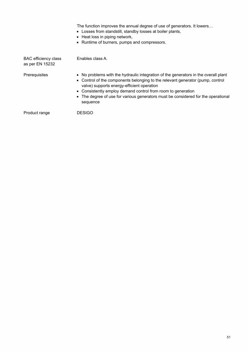
4.2.17 Operational sequence control of various generators based on generator efficiency
The function is intended to use priority control to adapt available generation output considering generator
degree of use. The function can be used to control … Multi-boiler plants, Multiple heat pumps, Multiple district heating relay stations, Combinations of aforementioned generators.
Heating generation Heating distribution Heating consumers
DemandDemand
M
The main supply temperature is formed by evaluating the heat demand of all consumers (heating circuits, domestic hot water generation, pre-control). Individual heating generators are controlled based on this temperature. We distinguish between lead and lag generators. The lead generator is always the first to be started.It always controls to the preset setpoint. The “switch-on” sequence of generators is set individually in the manner that the available generators achieve an overall high level of use. The application calculates the degree of use for the different generators, assigns the generator with the highest level of use as lead generator and specifies a setpoint for the enabled generator,and additionaly the individual stages are enabled based on demand. Additional generators are enabled in the sequence of their degree of use when the main flow temperature is below the neutral zone around the setpoint during a certain period. Adjustable delay times ensure a balanced output curve. Generators with a fault remain switched off by the application. Generators are once again brought online as soon as the fault is eliminated.
Sequence
Demand
HPHP
B2 St1
HP
B1
B1
B1
B1
HP
B2 St1
B2 St2
Boiler 2Boiler 1 Heat pump
Fuel oil
2-step
100 kW
η=0,9
Gas
modulating
100 kW
η=1,1continuous
50 kW
COP=4.7
Fig. 15 Example operational sequence control
Target
Use
Effect
Functioning
51
The function improves the annual degree of use of generators. It lowers… Losses from standstill, standby losses at boiler plants, Heat loss in piping network, Runtime of burners, pumps and compressors. Enables class A. No problems with the hydraulic integration of the generators in the overall plant Control of the components belonging to the relevant generator (pump, control
valve) supports energy-efficient operation Consistently employ demand control from room to generation The degree of use for various generators must be considered for the operational
sequence DESIGO
BAC efficiency class as per EN 15232
Prerequisites
Product range
52
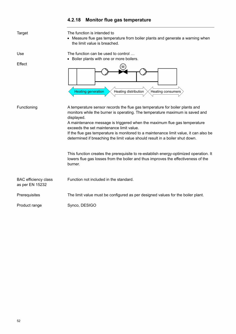
4.2.18 Monitor flue gas temperature
The function is intended to Measure flue gas temperature from boiler plants and generate a warning when
the limit value is breached. The function can be used to control … Boiler plants with one or more boilers.
Heating generation Heating distribution Heating consumers
M
A temperature sensor records the flue gas temperature for boiler plants and monitors while the burner is operating. The temperature maximum is saved and displayed. A maintenance message is triggered when the maximum flue gas temperature exceeds the set maintenance limit value. If the flue gas temperature is monitored to a maintenance limit value, it can also be determined if breaching the limit value should result in a boiler shut down. This function creates the prerequisite to re-establish energy-optimized operation. It lowers flue gas losses from the boiler and thus improves the effectiveness of the burner. Function not included in the standard. The limit value must be configured as per designed values for the boiler plant. Synco, DESIGO
Target
Use
Effect
Functioning
BAC efficiency class as per EN 15232
Prerequisites Product range

53
4.2.19 Charging control for domestic hot water
The function is intended to Generate and store domestic hot water (DHW) in buildings in an energy-
optimized manner. The function can be used to control … Domestic hot water generation.
A scheduler program enables the domestic hot water charge. The charge time enable results in energy savings (losses in storage tank) by defining the charger duration and preventing too frequent charges. A recharge occurs when the reduced domestic hot water temperature is breached even if the scheduler did not enable the charge. The supply temperature for domestic hot water charge is matched to the storage temperature dependent on demand. A demand-dependent supply temperature causes less heat loss at generation and distribution and spreading the load out over time (e.g. versus heat circuits) lowers the maximum output at generation which has a positive effect on the effectiveness of heating generation. Heating generation is often not designed to heat rooms and charge hot water at the same time. For multiple storage tanks, it is important to charge all storage at the same time to avoid maintaining a high supply temperature on a continuous basis or frequently increasing the temperature. Charging includes at least two sensors. Multiple sensors allow for dividing the storage tank into various charge zones and thus better adapt it to use. This reduces heat loss in the domestic hot water storage tank. The return temperature for the charge is controlled to as low a value as possible using variable water flow. It is required for condensing boilers (takes advantage of condensation heat) and districting heating (reduces transport losses) and heat pumps and saves energy. Enables class A. The function for managing domestic hot water storage tanks and flow generation controls (direct control without hot water storage tank) are not included. Sigmagyr, Synco, DESIGO
Target
Use
Effect
Functioning
BAC efficiency class as per EN 15232
Prerequisites
Product range

54
4.2.20 Circulation pump control
The function is intended to Supply domestic hot water in a building in a energy-optimized way. The function can be used to control … Circulation pump to immediately provide the desired temperature level in a
distributed domestic hot water network.
The water stored in a domestic hot water storage tank is continuously recirculated via hot water piping. The reason is that the water in the pipe cools down without a circulation pump and a user who turns on warm water initially gets cooled down water. This comfort disadvantage is balanced out via a circulation pump. High energy prices mean that a continuously operating circulation pump can become a considerable cost issue, especially if hot water piping is not or insufficiently insulated.
Heat loss from domestic hot water circulation is limited to actual occupancy and demand-dependent controlled. Measuring consumption or recording the return temperature (comparing desired and actual values) can be used to determine demand. The “windshield washer function” (periodic pump run, recording return temperature, deciding on whether a pump run is needed) can also be used to determine use. Enables class A. Hot water supply is equipped with a circulation pump. Sigmagyr, Synco, DESIGO
Target
Use
Effect
Functioning
BAC efficiency class as per EN 15232
Prerequisites Product range

55
4.3 Cooling supply 4.3.1 Outside air temperature dependent supply temperature
control
The function is intended to control building zones to… Supply rooms with the necessary cooling energy as the outside air temperature
rises, Consider occupancy. The function is used in chilled water control for… Fan coils, Chilled ceilings, TABS, Pre-control.
With outside air temperature based control, the required cooing output for a building zone is determined based on the outside air temperature. A sensor attached to the building's exterior shell records the outside air temperature. The required supply temperature is calculated per this measured value. This relationship provides the so-called cooling curve. You must be able to individually set the cooling curve to operate the cooling plant economically. Heat loss decreases or heat penetrates through the exterior shell to rooms as the outside air temperature increases. Rooms must be cooled to maintain the room temperature within the comfort range. For cooling surfaces (e.g. chilled ceilings) the cooling output changes by adapting the supply temperature of the water. The change in output is proportional to the temperature difference between room temperature and average cooling surface temperature. The outside air temperature is not always the measure for current cooling demand. Well-insulated buildings or buildings with effective solar protection facilities or with considerable storage mass do not need to be immediately supplied with lower supply temperatures as the outside air temperature increases. Outside air temperature compensation (attenuating the influence of changes to outside air temperature on the supply temperature) is used for the adjustment. Further considered are foreign energy sources inside that are not recorded by an outside sensor. This disadvantage can be minimized using a temperature sensor in the reference room that influences the supply temperature. Enables class C.
Target
Use
Effect
Functioning
BAC efficiency class as per EN 15232

56
Cooling circuit with control valve and circulating pump. Current scheduler with information on occupancy periods and times for setback
operation (vacation, night, holidays, etc.). Synco, DESIGO
Prerequisites
Product range

57
4.3.2 Switch-on/switch-off optimization (OSSC)
The function is intended to control building zones to… achieve as expanded a room temperature rise for cooling as possible at night,
on weekends and during vacation. The function is used in chilled water control for… Fan coils, Chilled ceilings. In larger buildings, the cooling circuits are divided by directions (e.g. north, south) or occupancy since, for example, the temperature level may vary.
The scheduler presets present “switch on”- and “switch off”-times for building zones. The calculation function is self-learning; it calculates the optimum start and stop times each in consideration of the outside air and room temperature. The “switch on”-time for cooling a building zone is calculated to achieve the desired temperature setpoint (interior temperature for the building zone) at the start of occupancy. The “switch off”-time for cooling a building zone is calculated so that the interior temperature increases at most by a preset value at the end of occupancy. Temperature sustained mode is triggered when the interior temperature increase above the set limit value. For cooling, the zone-internal setpoint is reduced at the start of the follow-on occupancy regardless of the time period of non-occupancy in the building zone. The temporary setpoint setback, e.g. after weekends or holidays, compensates for increased heating up of the building's exterior shell.
Fig. 16 Room temperature curve Switch on/switch off optimization Enables class A.
Target
Use
Effect
Functioning
BAC efficiency class as per EN 15232

58
A building zone may encompass one or multiple rooms controlled by the same plant and with the same occupancy.
A reference room is selected in each building zone. Its measured interior temperature is used as the actual value for the comfort temperature to control all the rooms belonging to this building zone. A room model may be used to calculate room temperature if no representative room temperature measurement is possible.
The hydraulic network must be balanced. The building time constant must be known. The reference room cannot be equipped with controlled valves. DESIGO
Prerequisites
Product range

59
4.3.3 Individual room control with electronic controller
The function is intended to Maintain the desired temperature in the room, Adapt room temperature and scheduled operation to occupancy, Compensate for external influences. The function can be used to control … Chilled ceilings, Fan coils.
An electronic temperature controller records the actual value for the room temperature with the help of a temperature sensor; compares it to a setpoint and then regulates to the desired setpoint via positioning unit. Intervention by the temperature controller is either triggered by a change to the setpoint or change in load. For example, a change of the ambient temperature. It is referred to as disturbance variable. Each change to a disturbance variable affects a change to the controlled variable. The element that executes the comparison between actual and setpoint value and specifies the value for the positioning equipment is referred to as controller. The positioning signal to the required actuating device, consisting of an actuator and positioning unit, is wireless or via fixed wiring. The following control strategies are possible corresponding to the selected actuator: 2-point control and pulse width modulation (PWM) (quasi-modulating). 3-point control (quasi-modulating). Modulating control. The thermostat is the most important form of a temperature controller and may have significant control deviations of up to 2 K (2-point) or tighter control deviations <0.5 K (quasi-modulating and modulating) depending on the controller type. In addition to control functions, electronic temperature controllers also includes other functions, including: Scheduler and calendar functions. Demand control with presence detector. Economy mode by evaluating window contacts. Operation and display. Operating modes such as:
Comfort mode, Economy mode, protection mode Dew point monitoring. Operating hours counter Communication
Target
Use
Effect
Functioning

60
A scheduler integrated on the controller allows for time-controlled operation of a room using temperatures dependent on occupancy, such as… Increase temperature for absences (holidays, working hours), Night increases, Comfort mode for occupancy. The function minimizes energy use. It permits… Different temperatures in separate rooms, Compensation for the influence of exterior sources of heat (sun), Compensation for the influence of interior sources of heat (people, light fixtures,
machines), Summer compensation of room temperature setpoints, And a time-controlled curve of the room air temperature. Enables Class C – for control without communication on a BAC system. Enables Class B – for control with communication on a BAC system. Enables Class A – for demand-control.. All rooms are equipped with electronic controllers Available functions are correctly commissioned and scheduler entries are
continuously adapted to occupancy. The runtimes and supply temperature for distribution and generation
components are controlled for demand control based on the required amount of energy in the room
Synco living, Synco, DESIGO
BAC efficiency class as per EN 15232
Prerequisites
Product range

61
4.3.4 Integrated individual room control with demand control
The function is intended to Maintain the desired temperature in the room, Achieve room conditions through user control, Generate cooling demand and transmit it to cooling distribution and generation
for processing, Evaluate window contacts to limit cooling output in the room, Allow scheduled preconditioning (PreComfort) of the room, Compensate for external influences. The function can be used to control … Chilled ceilings, Fan coils.
Individual room control is primarily responsible for controlling room temperature. A temperature sensor is used to record the actual value for room temperature; it is compared with the setpoint and calculated chilled water flow is controlled via a positioning unit. The individual room controller further processes all user interventions (setpoint, operating state) and room demands (room occupancy with presence detector, window contact, disturbance variables) and determines the cooling demand. The demand information is transmitted to cooling distribution and generation control for processing where it is used to determine whether the plant components must be switched on and the temperature level for consumers. An adjustable minimum limitation of room temperature helps prevent excessive cooling during control override (manual mode, actuator fault, etc.). The components room sensor, presence detector (with setpoint readjustment and display as applicable), window contact and control elements are normally wired to individual room controllers. A scheduler is available for each controller or room group for time-controlled operation of a room or zone using temperatures dependent on occupancy, such as… Preconditioning (PreComfort mode) prior to room occupancy, Increase in temperature for absences (holidays, working hours), The following control strategies are possible corresponding to the selected actuator: 2-point control with pulse width modulation (PWM) (quasi-modulating). 3-point control (quasi-modulating). Modulating control. Using individual room control improves control quality in the rooms, since it generally does not indicate any control deviations as is the case with traditional
Target
Use
Effect
Functioning

62
thermostats. This allows to maintain more precisely desired temperatures and more efficiently compensate heat gains. The application minimizes energy use. It permits… Different temperatures in separate rooms, Occupancy and time-controlled curves for desired room temperature, Compensation for the influence of exterior sources of heat (sun), Compensation for the influence of interior sources of heat (people, light fixtures,
machine), Summer compensation of room temperature setpoints, Close blinds to reduce incoming, radiated heat. a demand-controlled curve of the room air temperature. Enables class A. All rooms are equipped with individual room controllers and connected via a
network. Available functions are correctly commissioned and scheduler entries are
continuously adapted to occupancy. Demand control must evaluate the relevant controller information and control
supply temperature and operating times for distribution and generation components.
Synco living, Synco, DESIGO
BAC efficiency class as per EN 15232
Prerequisites
Product range

63
4.3.5 Cooling demand signal
The function is intended to Control cooling distribution and generation components by evaluating cooling
consumer valve settings, Generate and distribute cooling energy and temperature level by room demand. The function can be used to control … Cooling circuits, Charge chilled water storage, Pre-controls, Cooling generators.
The relevant information on all rooms belonging to a cooling circuit is collected. The values may consist of valve settings, room temperature or operating states. The demand signals from multiple sources are gathered, evaluated and mapped to resulting cooling demand signals. The valves and pumps are controlled based on these demand signals and the demand signals for the cooling energy generation are determined. The function reduces energy use. It lowers… – Operating hours of the circulating pumps, – Cooling loss in the piping network. Enables class A. Room controllers must be connected via network with the controllers for cooling distribution and generation and provide the necessary information. Synco, DESIGO
Target
Use
Effect
Functioning
BAC efficiency class as per EN 15232
Prerequisites
Product range

64
4.3.6 Differential pressure pump control
The function is intended to To equip circulating pumps with pressure differential control for cooling circuits
and generation as well as district pumps in variable volume piping networks to reduce electrical energy consumption.
The function should be used in supply networks where pressure differentials may occur due to variable cooling consumption; the differentials are compensated for by controlling flow volume: Cooling circuits where consumers are equipped with two-port valves. Main pumps supplying pressurized distribution District pumps with variable water flow
The pressure differential increases in the piping network as valves close due to reduced cooling demand (Fig. 17: 1). A pressure sensor records the change as a differential measurement. This pressure differential is maintained at a constant level by controlling volume flow rate with the help of a variable speed drive. Maintaining the pressure differential over the pump at a constant level significantly reduces the power consumption (Fig. 17: 2). Savings are increased by installing the pressure sensor at the "minus point" for the plant since this lowers pump pressure (pump head) and thus pump power consumption even more (Fig. 17: 3) to 3). The "minus point" for the plant is the point at which a minimum pressure differential is required to supply the consumer(s) with the necessary amount of water.
Fig.17 Pump characteristic curve
Target
Use
Effect
Functioning

65
The function reduces electrical energy consumption. Enables class A. The function is only used for hydraulic circuits where the volume flow rate at partial load operation is less than nominal load operation. Synco, DESIGO
BAC efficiency class as per EN 15232
Prerequisites
Product range

66
4.3.7 Control of TABS
The function is intended to Ensure year-round fully automated operation of TABS (thermally activated
building structure) while simultaneously meeting comfort requirements at the lowest possible energy consumption.
The function controls thermally activated building structures (TABS).
TABS control consists of modules "(heating curve)/cooling curve", "room temperature control", "Cycle operation for circulating pump" and "sequence control". The module "(Heating curve) / cooling curve" determines the outside air temperature compensated supply temperature for a cooling circuit. The curve is based on medium outside air temperature over the past 24 hours (gliding time window). The cooling curve uses this outside air temperature to establish the required supply temperature that ensures the desired comfort in the room. The nominal cooling curve applies to the nominal room temperature setpoint. The cooling curve gets shifted parallel when the desired room temperature setpoint is not equal to the nominal room temperature setpoint. The time-controlled adjustment to the cooling curve should be used when the rooms for the zone demonstrate different cooling loads in advance on known days. The adjustment is typically used to compensate for a lack of heat gains caused by non-occupancy over the weekends: The cooling curve is adjusted upward the weekend. The cooling limit determines whether to enable cooling based on the medium outside air temperature. The broad thermal inertia from TABS allows only a day-by-day correction to the room temperature using an optional room temperature control. It adjusts the position of the cooling curve to actual measured conditions. If recording is possible from one or more representative room temperatures in the zone, room temperature control will contribute to maintaining the desired comfort without under-cooling. Cycle operation saves, also available as an option, auxiliary energy, by temporarily switching off the zone pump. On the other hand, cycle operation also serves to establish the “switch on”-phases to allow for energy efficient and/or low-cost cooling production (for example, by re-cooling at night). Cycle operation can be adapted to the relevant circumstances – the characteristic of TABS and the type of cooling generation. Sequence control acts on control valves and the pump. It is designed for hydraulic circuits that allows the zone to control water flow and supply temperature via separate (heating and) cooling valves.
Target
Use
Effect
Functioning

67
The function supports in principle all hydraulic circuits that allow for constant flow through TABS when the zone pump is switched on. Summer/Winter compensation is available to adjust room temperature setpoints depending on the outside air temperature.
Fig. 18 Modular TABS zone control
The function reduces energy use. It lowers… Cooling loss (due to higher supply temperature) and allows for the efficient
operation of chillers or to take advantage of free cooling for longer periods, electrical energy consumption for circulating pumps significantly. Enables class A. The manual "TABS Control" (ISBN: 978-3-905711-05-9) describes in detail how to apply, design and control TABS. The book is currently only available in German. DESIGO
BAC efficiency class as per EN 15232
Prerequisites
Product range

68
4.3.8 Interlock of heating and cooling-side control
The function is intended to prevent A room from being heated and cooled simultaneously. The function can be used to control … Individual rooms or zones (building zone or/and room zone), Heating circuits, Cooling circuits, Heating and cooling generators.
The interlock between heating and cooling-side control in the room and/or distribution is one of the most important functions to save energy on heating and cooling in buildings. There are two ways to interlock: For partial interlock the setpoints of the generation and distribution are controlled by outside air temperature and can therefore only partially prevent the after treatment temperature controller from reheating in summer or recooling in winter. The interlock of the generation and distribution is more efficient, the wider apart the setpoints for heating and cooling are of all individual room controllers. The complete interlock represents the better and thus highly-efficient variant. It prevents any simultaneous heating and cooling in the room. This can be ensured by using sequence control in the individual room control. For distribution/generation, supply setpoints for cooling and heating must be prepared based on demand. This prevents the after treatment temperature controller from reheating in summer or recooling in winter. The function reduces energy use. It lowers… The useless generation of cooling or heating energy, Operating hours of the circulating pumps. Enables class A. The neutral zone between heating and cooling setpoints must be as large as
possible. Consistently use demand control Synco, DESIGO
Target
Use
Effect
Functioning
BAC efficiency class as per EN 15232
Prerequisites
Product range
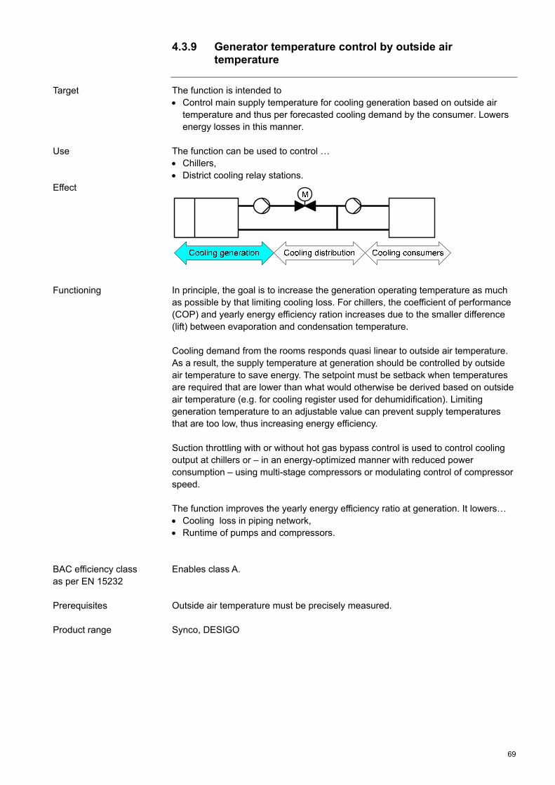
69
4.3.9 Generator temperature control by outside air temperature
The function is intended to Control main supply temperature for cooling generation based on outside air
temperature and thus per forecasted cooling demand by the consumer. Lowers energy losses in this manner.
The function can be used to control … Chillers, District cooling relay stations.
In principle, the goal is to increase the generation operating temperature as much as possible by that limiting cooling loss. For chillers, the coefficient of performance (COP) and yearly energy efficiency ration increases due to the smaller difference (lift) between evaporation and condensation temperature. Cooling demand from the rooms responds quasi linear to outside air temperature. As a result, the supply temperature at generation should be controlled by outside air temperature to save energy. The setpoint must be setback when temperatures are required that are lower than what would otherwise be derived based on outside air temperature (e.g. for cooling register used for dehumidification). Limiting generation temperature to an adjustable value can prevent supply temperatures that are too low, thus increasing energy efficiency. Suction throttling with or without hot gas bypass control is used to control cooling output at chillers or – in an energy-optimized manner with reduced power consumption – using multi-stage compressors or modulating control of compressor speed. The function improves the yearly energy efficiency ratio at generation. It lowers… Cooling loss in piping network, Runtime of pumps and compressors. Enables class A. Outside air temperature must be precisely measured. Synco, DESIGO
Target
Use
Effect
Functioning
BAC efficiency class as per EN 15232
Prerequisites Product range

70
4.3.10 Generator temperature control based on load
The function is intended to Control supply temperature at cooling generation by actual cooling demand at
the consumer. Keeps energy losses to a minimum. The function can be used to control … Chillers, District cooling relay stations.
In principle, the goal is to increase the operating temperature at generation as much as possible. For chillers, the coefficient of performance (COP) and yearly energy efficiency ratio increases due to the smaller difference (lift) between evaporation and condensation temperature. Cooling demand from all consumers (cooling circuits, pre-controls) and manual setpoint requirements, as applicable, are collected. The minimum value is derived from these setpoints. This value represents the actual load conditions and is used as setpoint for generation supply temperature. The risk exists when using a minimum selection for a single room as the temperature level that this temperature is too low for other consumers. Using the average of multiple rooms to determine the temperature level ensures that all consumers can cover their cooling demand. Limiting generation temperature to an adjustable value can prevent supply temperatures that are too low, thus increasing energy efficiency. Suction throttling with or without hot gas bypass control is used to control cooling output at chillers or – in an energy-optimized manner with reduced power consumption – using multi-state compressors or modulating control of compressor speed. The function improves the annual degree of use at generation. It lowers… Cooling loss in piping network, Runtime of pumps and compressors. Enables class A. Consistently employ demand control from room to generation. Synco, DESIGO
Target
Use
Effect
Functioning
BAC efficiency class as per EN 15232
Prerequisites
Product range

71
4.3.11 Operational sequence control of various generators based on load
The function is intended to use priority control to adapt the available generation output to current load in an
energy efficient manner. The function can be used to control … Multiple chillers, Multiple district cooling relay stations, Combinations of aforementioned generators.
The main supply temperature is formed by evaluating the cooling demand of all consumers (cooling circuits, pre-control). Individual cooling generators are controlled based on this temperature. We distinguish between lead and lag generators. The lead generator is always the first to be switched on. It always controls to the preset setpoint. An automated changeover of lead generator and thus the connected operating sequence can occur depending on the operating hours for lead generator. An adjustable priority specification controls the “switch-on” sequence of generators. Additional generators are switched on as output demand increases; starting initially with the first stage and then to the second for additional output demand or generation modulation is enabled. The application decides in consideration of all influences on enabling generation, specifies a setpoint for the enabled generation and then additionally enables individual stages based on demand. Additional generators are only enabled when the main supply temperature is above the neutral zone around the setpoint during a certain period. Adjustable delay times ensure a balanced output curve. Generators with a fault remain switched off by the application. Generators are once again brought online as soon as the fault is eliminated. The function improves the yearly energy efficiency ratio of the generation. It lowers… Cooling loss in piping network, Runtime of pumps and compressors. Enables class C. No problems with the hydraulic integration of the generators in the overall plant Control of the components belonging to the relevant generator (pump, control
valve) supports energy-efficient operation Consistently employ demand control from room to generation Synco, DESIGO
Target
Use
Effect
Functioning
BAC efficiency class as per EN 15232
Prerequisites
Product range

72
4.3.12 Operational sequence control of various generators based on load and generator capacities
The function is intended to use priority control to adapt available generation output to current load in an
energy efficient manner considering the generation output. The function can be used to control … Multiple chillers, Multiple district cooling relay stations, Combinations of aforementioned generators.
The main supply temperature is formed by evaluating the cooling demand of all consumers (cooling circuits, pre-control). Individual cooling generators are controlled based on this temperature. We distinguish between lead and lag generators. The lead generator is always the first to be switched on. It always controls to the preset setpoint. The “switch-on” sequence of generators is preset based on generator output. For generators with different output (e.g. the second generator is twice as large as the first) it is possible to bring second generator on line and then switched off the first generator. The first generator is only switched on again when the second generator has both stages switched (the maximum output is achieved, includes both multi-stage and modulating generation). This achieves improved output stages. The function decides in consideration of all influences on enabling a generator, specifies a setpoint for the enabled generator and then additionally enables individual stages based on demand. Additional generators are only enabled when the main supply temperature is above the neutral zone around the setpoint during a certain period. Adjustable delay times ensure a balanced output curve. Generators with a fault remain switched off by the application. Generators is once again brought online as soon as the fault is eliminated. The function improves the yearly energy efficiency ratio at generation. It lowers… Cooloing loss in piping network, Runtime of pumps and compressors. Enables Class B.
Target
Use
Effect
Functioning
BAC efficiency class as per EN 15232

73
No problems with the hydraulic integration of the generators in the overall plant Control of the components belonging to the relevant generators (pump, control
valve) supports energy-efficient operation Consistently employ demand control from room to generation Generator outputs and load ratios must be considered in the operating sequence Synco, DESIGO
Prerequisites
Product range

74
4.3.13 Operational sequence control of various generators based on generator efficiency
The function is intended to use priority control to adapt of available generation output considering generator
degree of use. The function can be used to control … Multiple chillers, Multiple district cooling relay stations, Combinations of aforementioned generators.
The main supply temperature is formed by evaluating the cooling demand of all consumers (cooling circuits, pre-control). Individual cooling generators are controlled based on this temperature. We distinguish between lead and lag generators. The lead generator is always the first to be switched on. It always controls to the preset setpoint. The “switch-on” sequence of generators is set individually in the manner that the available generators achieve an overall high level of use. The application calculates the degree of use for various generators, assigns the generator with the highest degree of use as lead generator and specifies a setpoint for enabled generator. And additionaly the individual stages are enabled based on demand. Additional generators are enabled in the sequence of their degree of use when the main flow temperature is above the neutral zone around the setpoint during a certain period. Adjustable delay times ensure a balanced output curve. Generators with a fault remain switched off by the application. Generators are once again brought online as soon as the fault is eliminated. The function improves the yearly energy efficiency ratio of the cooling generation. It lowers… Cooling loss in piping network, Runtime of pumps and compressors. Enables class A. No problems with the hydraulic integration of generators in the overall plant Control of the components belonging to the relevant generator (pump, control
valve) supports energy-efficient operation Consistently employ demand control from room to generation. The degree of use for various generators must be considered for the operational
sequence DESIGO
Target
Use
Effect
Functioning
BAC efficiency class as per EN 15232
Prerequisites
Product range

75
Index
B Building automation and control as the basis for
energy optimized operation................................. 8
C Charging control for domestic hot water............... 53 Circulation pump control ....................................... 54 Control of TABS .............................................. 42, 66 Cooling demand signal ......................................... 63 Copyright ................................................................ 6
D Differential pressure control of pumps.................. 37
E Energy efficiency in building automation and control
.......................................................................... 10
F Factors influencing energy consumption in buildings7
G Generator temperature control based on load 45, 70 Generator temperature control by outside air
temperature................................................. 44, 69
H Heating demand signal......................................... 36 Heating limit switch............................................... 25
I Individual room control using thermostatic radiator
valves ................................................................ 30 Individual room control with electronic controller.. 32 Integrated individual room control with demand
control................................................................ 34 Interlock of heating and cooling-side control ........ 68
M Model for demand and supply .............................. 16 Monitor flue gas temperature................................ 52
N Night setback / quick setback................................27
O Operating modes and setpoints ............................20 Operational sequence control of various generators
based on generator efficiency......................50, 74 Operational sequence control of various generators
based on load ..............................................46, 71 Operational sequence control of various generators
based on load and generator capacities............48 Operational sequence control of various generators
based on load and generator capacities............72 Outside air-temperature dependent supply
temperature control......................................22, 55
P Predictive heating control ......................................39 Principle of energy-efficient operation...................12
Q Quality assurance....................................................6
R Reduce supply temperature ..................................24 Requirements for energy-efficient control .............13
S Scheduler ..............................................................19 Structure of optimum energy generation generation
...........................................................................14 Switch-on/switch off optimization (OSSC).............28
T Target readership ....................................................6 Term energy efficiency ............................................9

76/80
Building Technologies Index

77
Notes

78


www.siemens.com/energy-efficiency
■ Megatrends driving the futureThe megatrends – demographic change, urbanization, climate change, and globali zation – are shaping the world today. These have an unprecedented impact on our lives and on vital sectors of our economy.
■ Innovative technologies to answer the associated toughest questions
Throughout a 160year history of proven research and engineering talent, with more than 50,000 active patents, Siemens has continuously provided its customers with innovations in the ar eas of healthcare, energy, industry, and in frastructure – globally and locally.
■ Increase productivity and efficiency through complete building life cycle management
Building Technologies offers intelligent integrated solutions for industry, commercial and residential buildings, and public infrastructure. Over the entire fa cility’s life cycle, our comprehensive and environmentally conscious port fo lio of products, systems, solutions, and services for lowvoltage power distribution and electrical installation technology, building automation, fire safety and security ensures the:– optimum comfort and highest energy
efficiency in buildings,– safety and security for people,
processes, and assets,– increased business productivity.
Answers for infrastructure.
The information in this document contains general descriptions of technical options available, which do not always have to be present in individual cases. The required features should therefore be specified in each individual case at the time of closing the contract.
© Siemens Switzerland Ltd, 2010
Siemens Switzerland LtdIndustry SectorBuilding Technologies DivisionInternational HeadquartersGubelstrasse 226301 ZugSwitzerlandTel +41 41 724 24 24
Siemens Building TechnologiesIndustry SectorBrunel HouseSir William Siemens Square, FrimleyCamberleySurrey, GU16 8QDUnited KingdomTel +44 1276 696000
Siemens LtdIndustry SectorBuilding Technologies Division22/F, Two Landmark East100 How Ming Street, Kwun Tong Kowloon, Hong KongTel +852 2870 7888