Embed Size (px)
Citation preview

ULG Montefiore. 18/11/09
© Siemens AG 2006
Power Transmission and DistributionA.Belvaux
Energy –a core sector at Siemens
Industry SectorEnergy SectorHealthcare Sector

ULG Montefiore. 18/11/09
© Siemens AG 2006
Power Transmission and DistributionA.Belvaux
Siemens Energy Sector –Answers for energy supply
Energy Products and Solutions - in 6 Divisions
Power Distribution
Power Trans-mission
Energy Service
RenewableEnergy
Fossil PowerGeneration
Oil & Gas

ULG Montefiore. 18/11/09
© Siemens AG 2006
Power Transmission and DistributionA.Belvaux
The electricity network ensure an efficient supply of energy
High Voltage Transformers Medium VoltageComponents, switchgear and turnkey projects for AC and DC power
technology for power transmission ≤ 52 kV.
Components, switchgear and turnkey
projects for AC and DC power technology for power transmission
> 52 kV.
Power transformers, distributiontransformers with oil or cast-resin
insulation.
Energy AutomationNetwork control systems, protection
and substation automation, telecontrol systems, power quality.
ServicesNetwork planning & consulting, asset
maintenance and maintenance management for grids and networks, metering services.
ULG Montefiore. 18/11/09
© Siemens AG 2006
Power Transmission and DistributionA.Belvaux
Energy flow in electricity networks
Domestic Industry
Main power station
0.4 kV
15 kV
150 kV
DomesticCombinedheat power
Solar
Storage
Combinedindustrialprocesses
WindHydro
Biomass
Fuel cell
150 kV
15 kV
0.4 kV
+ -
ULG Montefiore. 18/11/09
© Siemens AG 2006
Power Transmission and DistributionA.Belvaux
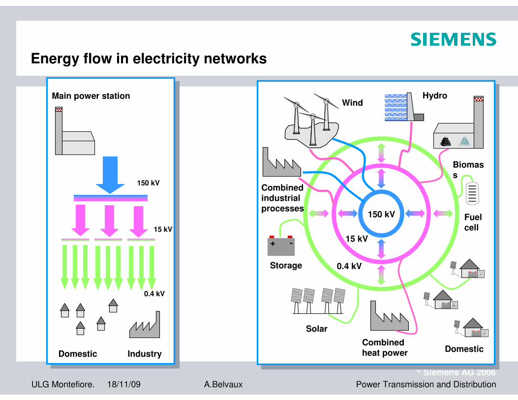
Power Transmission Division –The link between power generation and distribution
ULG Montefiore. 18/11/09
© Siemens AG 2006
Power Transmission and DistributionA.Belvaux
63
50
40
31,5
25
0
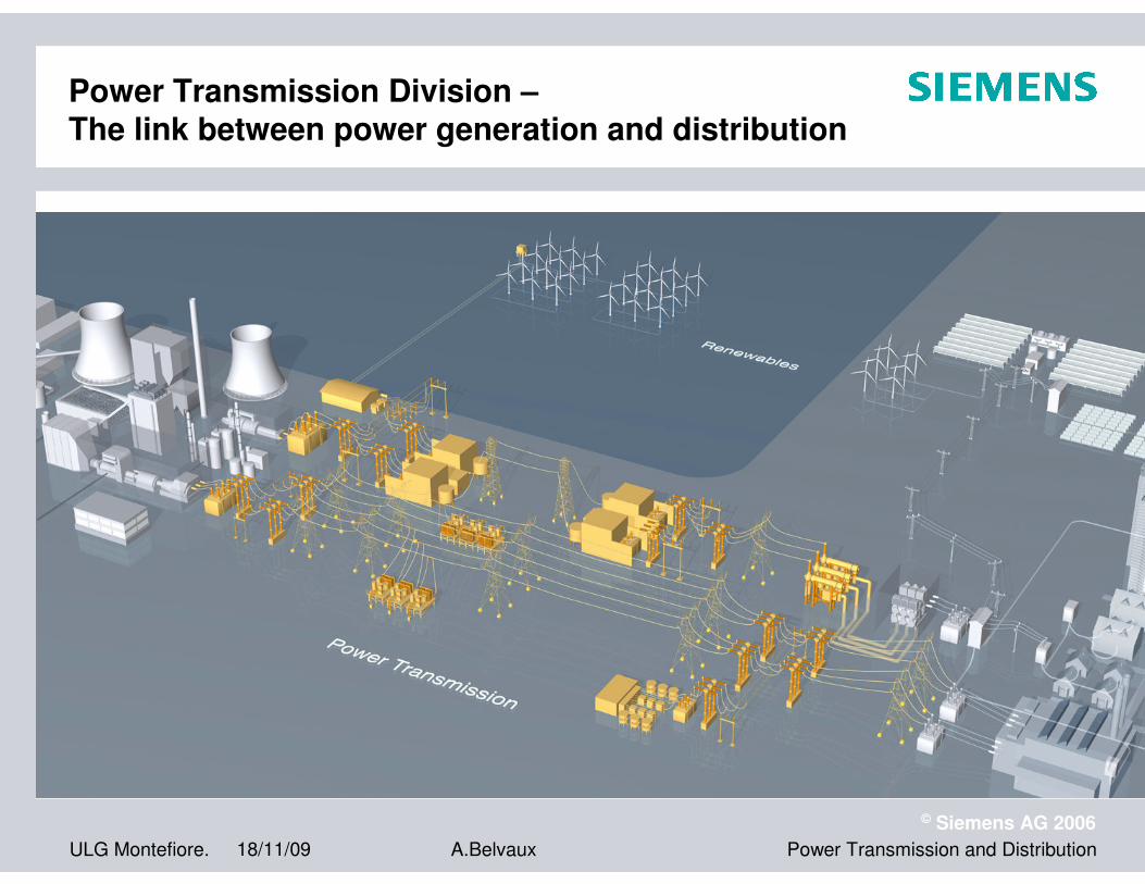
Rated short-circuit breaking current [kA]
72,5 123 145 300 362 420 550 800Rated voltage [kV]
170 245
80
3AT2/3 3AT4/5
3AP1 FI3AP1 FG 3AP2 FI
Key Product for High VoltageNetwork: Circuit Breaker

ULG Montefiore. 18/11/09
© Siemens AG 2006
Power Transmission and DistributionA.Belvaux
Type 3AP1 FG up to 245 kV
�For all applications: reliable and economical
�Stored energySpring Drive Mechanism
�Self compression arc quenching principle
�Rated voltages up to 245 kV
�Rated short circuit breaking current up to 50 kA
�Type tested to the new IEC 62271-100
�Available for one or three pole operation (FG/FI)
�Delivered more than 50,000 breakers to more than 120 countries
Type 3AP1 FI up to 300 kV
� Stored energy Spring Drive Mechanism
� Self compression arc quenching principle
� Rated voltages up to 300 kV
� Rated short circuit breaking current up to 50 kA
� Type tested to the new IEC 62271-100
High-Voltage Circuit-Breaker Product Characteristics
ULG Montefiore. 18/11/09
© Siemens AG 2006
Power Transmission and DistributionA.Belvaux
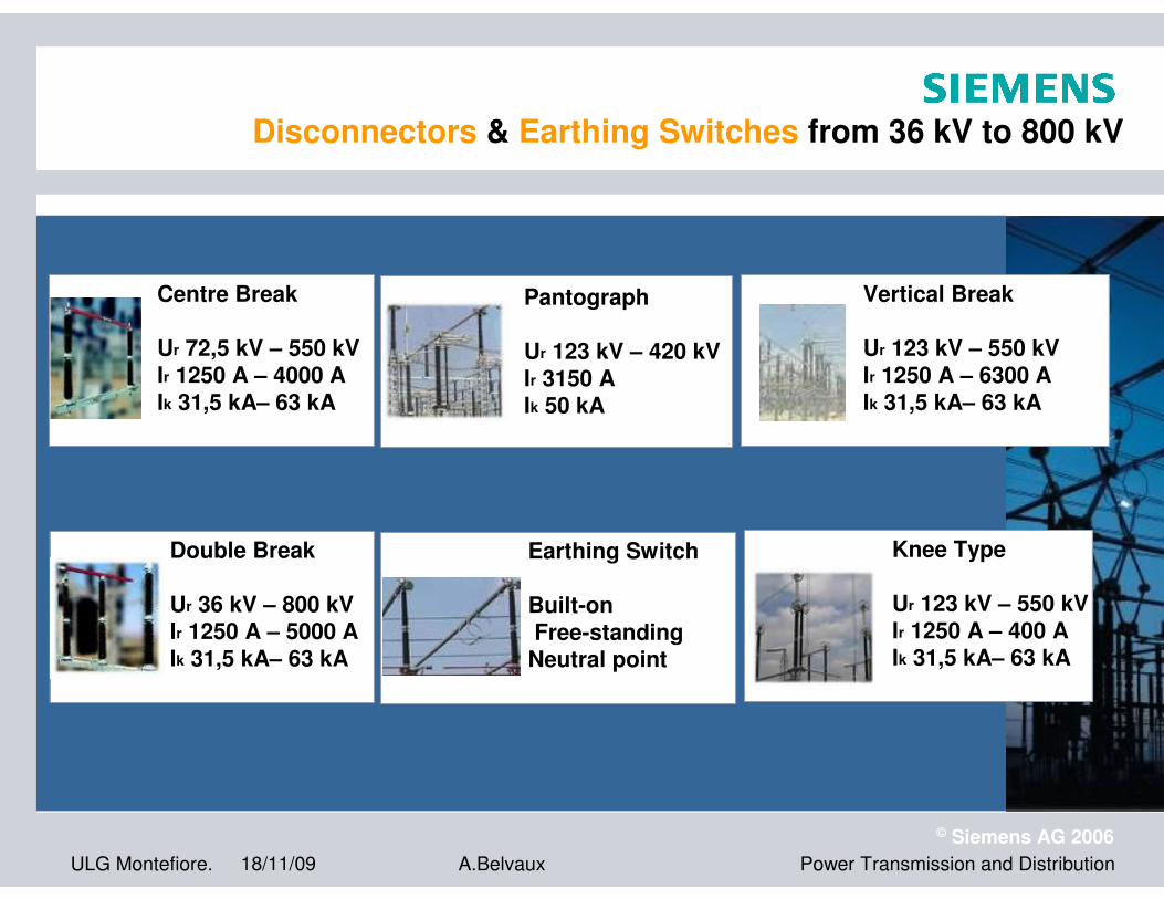
Centre Break
Ur 72,5 kV – 550 kVIr 1250 A – 4000 AIk 31,5 kA– 63 kA
Pantograph
Ur 123 kV – 420 kVIr 3150 AIk 50 kA
Vertical Break
Ur 123 kV – 550 kVIr 1250 A – 6300 AIk 31,5 kA– 63 kA
Earthing Switch
Built-onFree-standing
Neutral point
Double Break
Ur 36 kV – 800 kVIr 1250 A – 5000 AIk 31,5 kA– 63 kA
Knee Type
Ur 123 kV – 550 kVIr 1250 A – 400 AIk 31,5 kA– 63 kA
Disconnectors & Earthing Switches from 36 kV to 800 kV

ULG Montefiore. 18/11/09
© Siemens AG 2006
Power Transmission and DistributionA.Belvaux
Instrument Transformers
� Current Transformers
� Voltage Transformers
Bushings
� Air Core Dry Type Reactors
� Line Traps
� Arc Suppression Coils
Coils
� Air Core Dry Type Reactors
� Line Traps
� Arc Suppression Coils
Arrester
� HV: AIS (Porcellain, Polymer) & GIS; HVDC, FACTS
� MV: Distribution & Traction Vehicles
Products for High VoltageArrestors, Bushings, Coils & Instrument Transformers
ULG Montefiore. 18/11/09
© Siemens AG 2006
Power Transmission and DistributionA.Belvaux
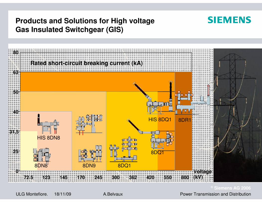
Voltage (kV)
80
72.5
63
50
40
25
0
123 145 300 362 420 550 800
8DR1
8DQ1
8DN9
170 245
HIS 8DN8
HIS 8DQ1
8DN8
Rated short-circuit breaking current (kA)
8DQ1
31,5
Products and Solutions for High voltageGas Insulated Switchgear (GIS)
ULG Montefiore. 18/11/09
© Siemens AG 2006
Power Transmission and DistributionA.Belvaux
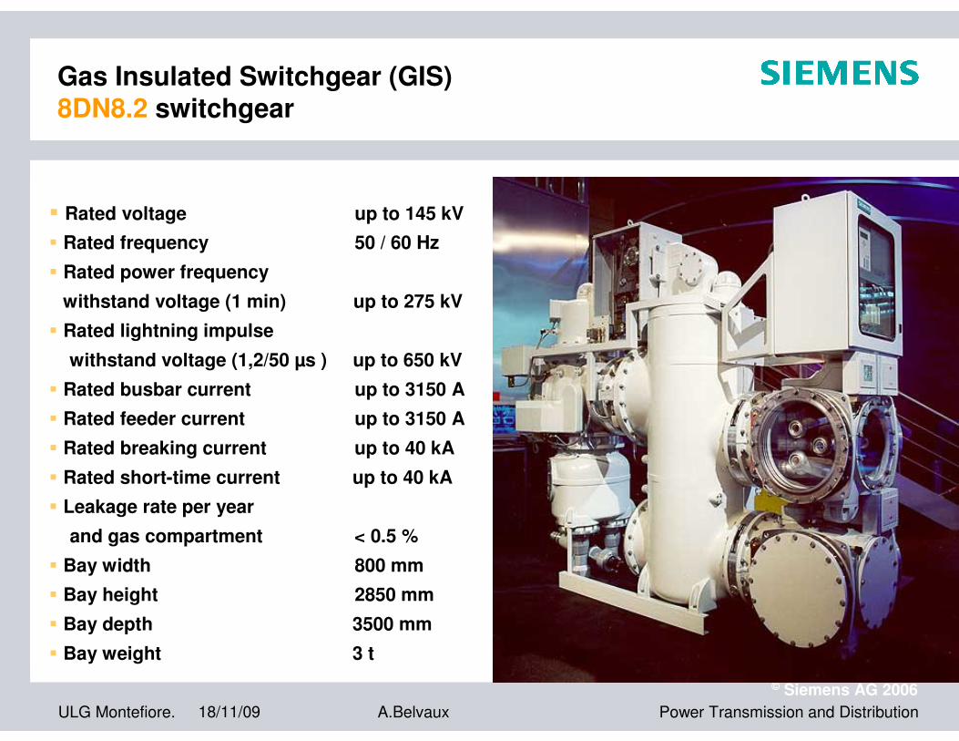
� Rated voltage up to 145 kV
� Rated frequency 50 / 60 Hz
� Rated power frequency
withstand voltage (1 min) up to 275 kV
� Rated lightning impulse
withstand voltage (1,2/50 µs ) up to 650 kV
� Rated busbar current up to 3150 A
� Rated feeder current up to 3150 A
� Rated breaking current up to 40 kA
� Rated short-time current up to 40 kA
� Leakage rate per year
and gas compartment < 0.5 %
� Bay width 800 mm
� Bay height 2850 mm
� Bay depth 3500 mm
� Bay weight 3 t
Gas Insulated Switchgear (GIS)8DN8.2 switchgear

ULG Montefiore. 18/11/09
© Siemens AG 2006
Power Transmission and DistributionA.Belvaux
Gas Insulated Switchgear (GIS) 8DN9 switchgear
�Rated voltage up to 245 kV
�Rated frequency 50 / 60 Hz
�Rated power frequency
withstand voltage (1 min) up to 460 kV
�Rated lightning impulse
withstand voltage (1,2/50 µs) up to 1050 kV
�Rated busbar current up to 3150 A
�Rated feeder current up to 3150 A
�Rated breaking current up to 50 kA
�Rated short-time current up to 50 kA
�Leakage rate per year and
gas compartment < 0.5 %
�Bay width 1500 mm
�Bay height 3500 mm
�Bay depth 4700 mm
�Bay weight 5 t
ULG Montefiore. 18/11/09
© Siemens AG 2006
Power Transmission and DistributionA.Belvaux
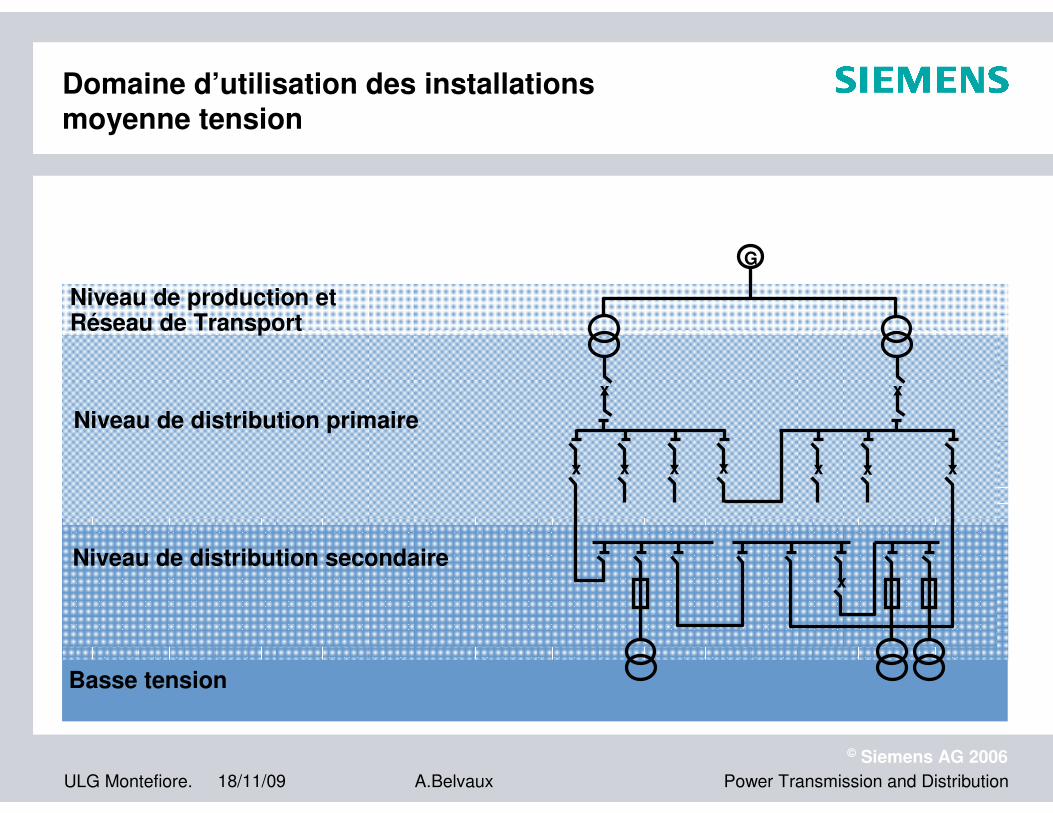
Domaine d’utilisation des installationsmoyenne tension
G
x x
x xxx xx x
x
Niveau de production et Réseau de Transport
Niveau de distribution primaire
Niveau de distribution secondaire
Basse tension

ULG Montefiore. 18/11/09
© Siemens AG 2006
Power Transmission and DistributionA.Belvaux
� High reliability
� Excellent field experience with more than 2
million vacuum interrupters
� Tailormade development
� Wide product range for any application
� For use in
� LV and MV circuit-breakers, load-break
switches and contactors
� Autoreclosers
� Transformer Tap Changers
Delivery Program
690 up to 1300 V up to 65 kA up to 2500 A
7.2 up to 40.5 kV up to 72 kA up to 6300 A
Medium Voltage ComponentsVacuum Tubes

ULG Montefiore. 18/11/09
© Siemens AG 2006
Power Transmission and DistributionA.Belvaux
8DA
� Type-tested, single-phase encapsulation, metal-clad
� Proved design, Single Busbar
� Modular design with standard enclosures allows single- and double phase applications
� More than 15 years of operating experience
Medium Voltage Products for Primary DistributionSF6-Insulated Switchgear
8DB
� Type-tested, single-phase encapsulation, metal-clad
� Proved design, Double Busbar
� Modular design with standard enclosures
� Busbars and busbar-disconnectors in separate gas compartments
� More than 15 years of operating experience
Delivery Program
up to 40.5 kV up to 40 kA up to 4000 A
Delivery Program
up to 40.5 kV up to 40 kA up to 4000 A

ULG Montefiore. 18/11/09
© Siemens AG 2006
Power Transmission and DistributionA.Belvaux
8DJ20
� Type-tested
� Independent of climate
� Maintenance-free
� Block-type construction, for 1-5 bays
� Hermetically-sealed welded switch-gear enclosures
� Compact and clear design
� No sealings
� Highest Quality Level
� Shortest Delivery Periods
8DJ10
� Type-tested
� Independent of climate
� Maintenance-free
� Block-type construction, for 3-6 bays
� Hermetically-sealed welded switch-gear enclosures
� Compact and clear design
� No sealings
� Highest Quality Level
� Shortest Delivery Periods
� Smallest floor space for substations
Delivery Program
up to 24 kV up to 25 kA up to 630 A
Delivery Program
up to 24 kV up to 25 kA up to 630 A
Medium Voltage Products for Secondary DistributionSF6-Insulated Switchgear
ULG Montefiore. 18/11/09
© Siemens AG 2006
Power Transmission and DistributionA.Belvaux
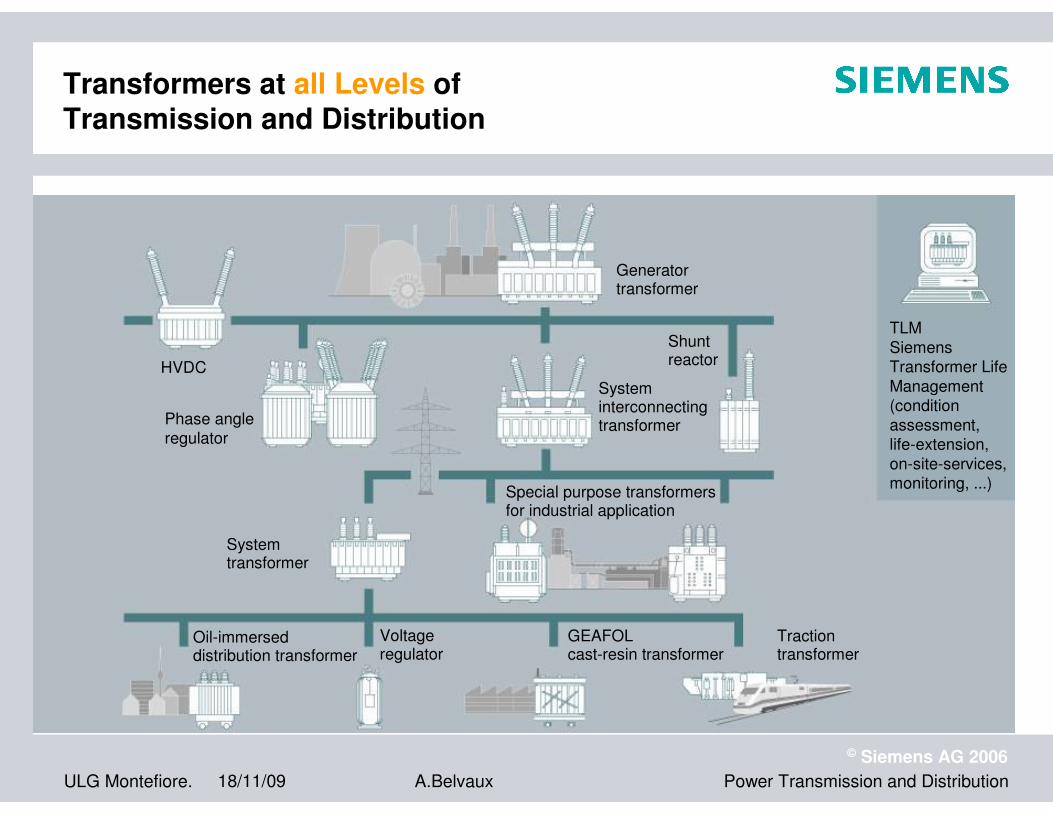
Generatortransformer
Systeminterconnectingtransformer
Shunt reactor
Oil-immerseddistribution transformer
GEAFOLcast-resin transformer
Tractiontransformer
HVDC
Systemtransformer
Special purpose transformers for industrial application
Voltageregulator
Phase angle regulator
TLM
Siemens Transformer Life
Management(condition
assessment,life-extension,
on-site-services,monitoring, ...)
Transformers at all Levels of Transmission and Distribution

ULG Montefiore. 18/11/09
© Siemens AG 2006
Power Transmission and DistributionA.Belvaux
Energy Automation
Do lor situs cum
habilitarum itum
alus causticus
imanenter Status
landum exus rius
laudanum tum.
Lorem exit vulnareus
plexus est. Vulna
pausta rhus tex, per
itum falor sit wunt.
Sit itum causticus
aurum eum et expli
ndus.Cum
� Information and
network control
technology
� Protection and
substation auto-
mation, telecon-trol
systems, power
quality
ULG Montefiore. 18/11/09
© Siemens AG 2006
Power Transmission and DistributionA.Belvaux
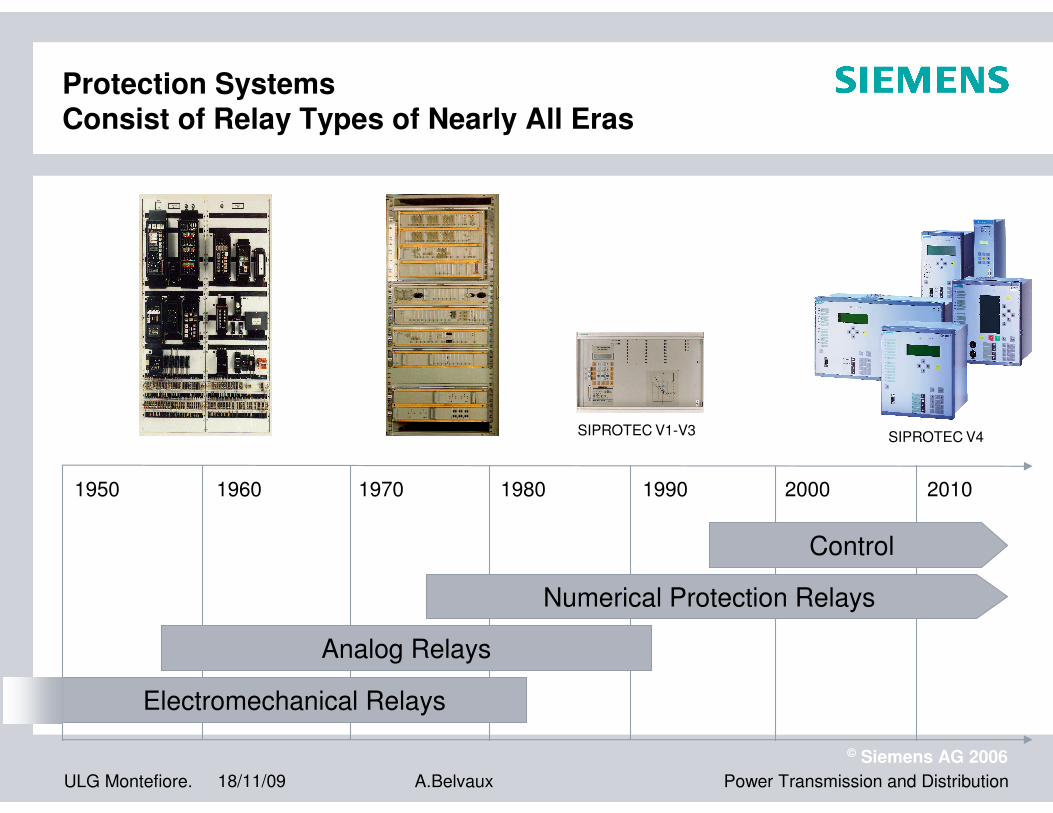
Protection SystemsConsist of Relay Types of Nearly All Eras
1950 1960 1970 1980 1990 2000 2010
Analog Relays
Control
Numerical Protection Relays
SIPROTEC V1-V3 SIPROTEC V4
Electromechanical Relays

ULG Montefiore. 18/11/09
© Siemens AG 2006
Power Transmission and DistributionA.Belvaux
Protection SystemsConsist of Relay Types of all Nearly All Manufacturers

ULG Montefiore. 18/11/09
© Siemens AG 2006
Power Transmission and DistributionA.Belvaux
LE BUT DE LA PROTECTION SELECTIVE EST:-Assurer la continuité de service du réseau d’energie , par
élimination de l’élément défaillant et de lui seul-Eviter des dégâts au niveau des équipements affectés par
les défauts(câbles,transformateurs…)
SIPROTEC 4
ULG Montefiore. 18/11/09
© Siemens AG 2006
Power Transmission and DistributionA.Belvaux
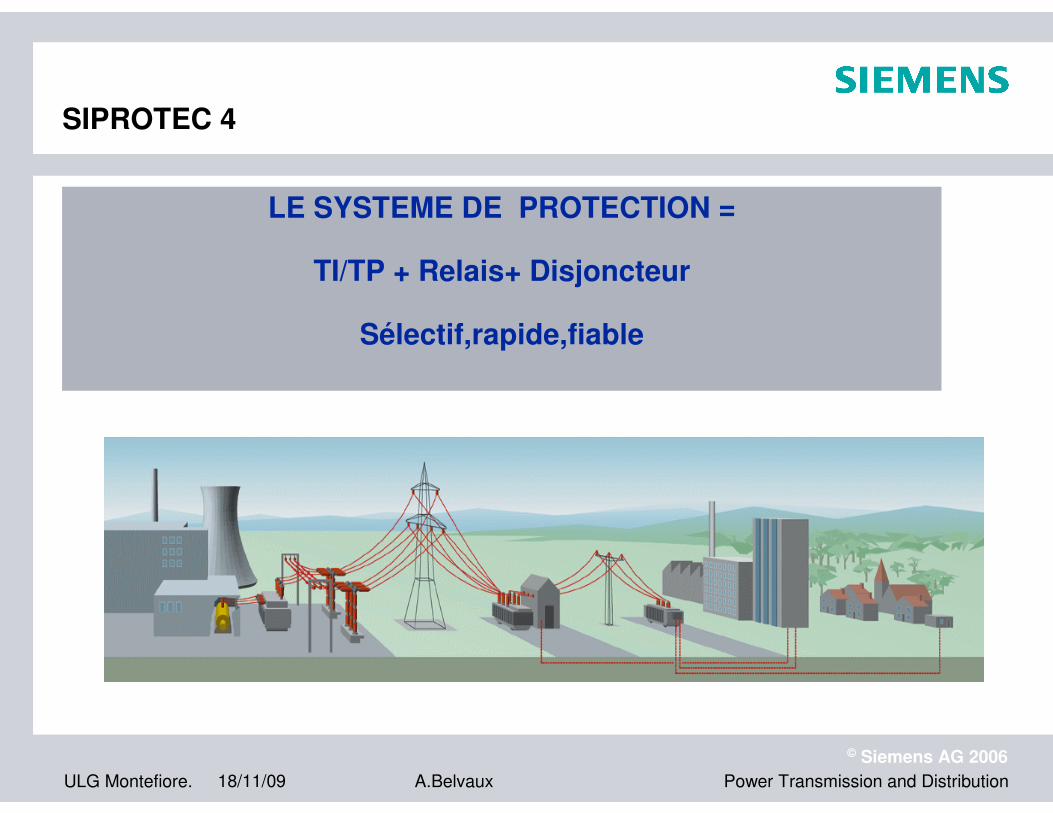
LE SYSTEME DE PROTECTION =
TI/TP + Relais+ Disjoncteur
Sélectif,rapide,fiable
SIPROTEC 4

ULG Montefiore. 18/11/09
© Siemens AG 2006
Power Transmission and DistributionA.Belvaux
Protection SystemsStandard Structure
circuitbreakercontrol
circuitbreaker
signalsampling
signalprocessing
signalanalysis
Trip signal formation
Protection Equipment
auxiliarypower
SystemV, A
signaladaption
SystemkV, kA
protectionobject

ULG Montefiore. 18/11/09
© Siemens AG 2006
Power Transmission and DistributionA.Belvaux
Protection SystemsQuality and Security
Stabilityavoids breakdown by false tripping
Speedlimits damages
maintains stability
limits breakdown amountincreases availability
Selectivity
avoids overfunctionavoids underfunction
Security
Modern
Protection System
ULG Montefiore. 18/11/09
© Siemens AG 2006
Power Transmission and DistributionA.Belvaux
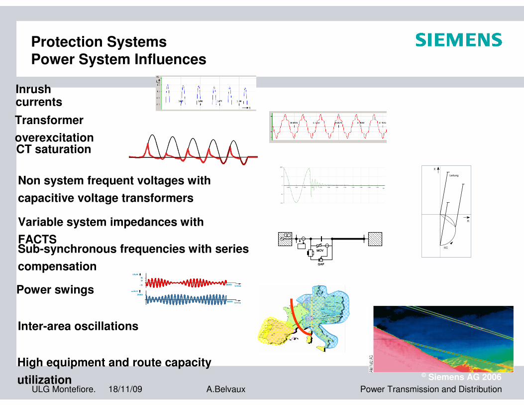
Protection SystemsPower System Influences
High equipment and route capacity
utilization
i1
t
i1
t
Inrush currents
Transformer
overexcitationCT saturation
t/s0,995 1,000 1,005 1,010 1,015 1,020 1,025 1,030 1,035 1,040 1,045 1,050
U/V
-100
-50
0
50
Non system frequent voltages with
capacitive voltage transformers
-XC
Leitung
R
X
-XC
Leitung
R
X
Variable system impedances with
FACTS
GAP
MOV
ZS
GAP
MOV
ZS
Sub-synchronous frequencies with series
compensationi/kA
t/ms500
u/kV
t/ms500
200
-3
6
3
i/kA
t/ms500
u/kV
t/ms500
200
-3
6
3
Power swings
Inter-area oscillations
ULG Montefiore. 18/11/09
© Siemens AG 2006
Power Transmission and DistributionA.Belvaux
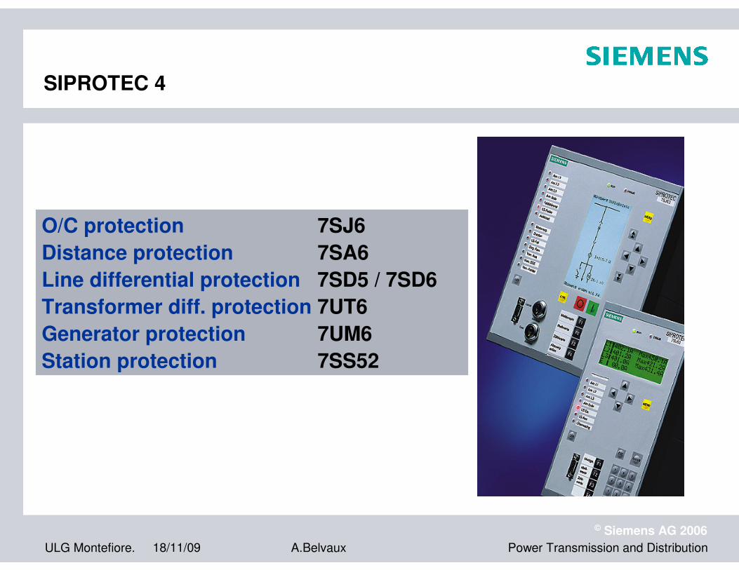
O/C protection 7SJ6
Distance protection 7SA6
Line differential protection 7SD5 / 7SD6
Transformer diff. protection 7UT6
Generator protection 7UM6
Station protection 7SS52
SIPROTEC 4
ULG Montefiore. 18/11/09
© Siemens AG 2006
Power Transmission and DistributionA.Belvaux
O/C protection7SJ6
SIPROTEC 4

ULG Montefiore. 18/11/09
© Siemens AG 2006
Power Transmission and DistributionA.Belvaux
Time-overcurrent protection Functions
Time-overcurrent protection
Criteria for fault: overcurrent
Criteria for selectivity: time
ULG Montefiore. 18/11/09
© Siemens AG 2006
Power Transmission and DistributionA.Belvaux
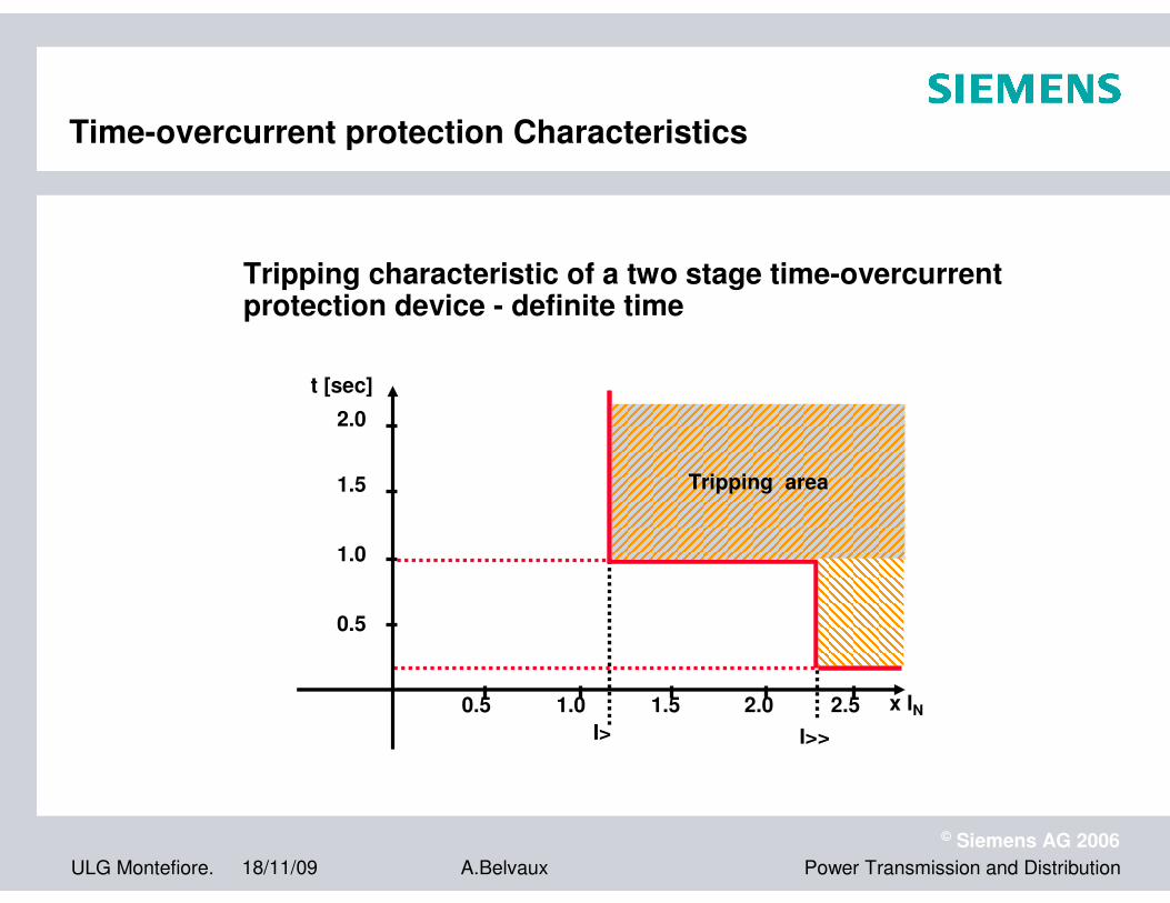
Time-overcurrent protection Characteristics
t [sec]
0.5
1.0
1.5
2.0
x IN0.5 1.0 1.5 2.0 2.5
I> I>>
Tripping area
Tripping characteristic of a two stage time-overcurrent protection device - definite time

ULG Montefiore. 18/11/09
© Siemens AG 2006
Power Transmission and DistributionA.Belvaux
Time-overcurrent protection Application
Used as:
Line protectionSelectivity by time-grading
1
x
O/C
x
O/C
1
x
M
O/C
2
x
O/C
3
As main protection
2 Motor protectionwith short circuit- and overload protection,start protection,start inhibit
3 Transformer protectionfor network transformerswith short circuit- and overload protection,Inrush-stabilisation

ULG Montefiore. 18/11/09
© Siemens AG 2006
Power Transmission and DistributionA.Belvaux
Time-overcurrent protection Application
Main protection as line protection
x x x x
O/C O/C O/C O/C
t = 0mst = 300mst = 600mst = 900ms
Advantage: simple device,only current transformers are necessary
Disadvantage: near infeed higher tripping time
Ttrip
distance
backup
ULG Montefiore. 18/11/09
© Siemens AG 2006
Power Transmission and DistributionA.Belvaux
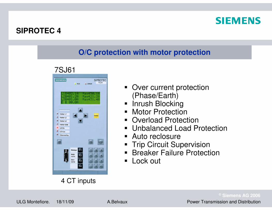
4 CT inputs
7SJ61
O/C protection with motor protectionO/C protection with motor protection
� Over current protection(Phase/Earth)
� Inrush Blocking� Motor Protection� Overload Protection� Unbalanced Load Protection� Auto reclosure� Trip Circuit Supervision� Breaker Failure Protection� Lock out
SIPROTEC 4

ULG Montefiore. 18/11/09
© Siemens AG 2006
Power Transmission and DistributionA.Belvaux
Distance protectionDistance protection
SIPROTEC 4
ULG Montefiore. 18/11/09
© Siemens AG 2006
Power Transmission and DistributionA.Belvaux
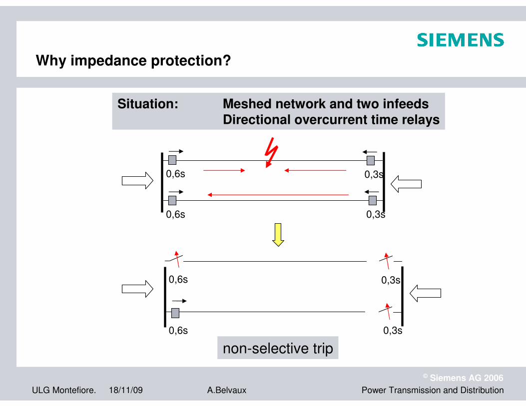
Why impedance protection?
Situation: Meshed network and two infeedsDirectional overcurrent time relays
0,6s
0,6s
0,3s
0,3s
0,6s
0,6s
0,3s
0,3s
non-selective trip

ULG Montefiore. 18/11/09
© Siemens AG 2006
Power Transmission and DistributionA.Belvaux
Localization of short-circuits by means of an impedance measurement:
� fault on the protected line
� fault outside the protected line
Z1
relay A
selectivity
relay A
Z2
Basic principle of impedance protection

ULG Montefiore. 18/11/09
© Siemens AG 2006
Power Transmission and DistributionA.Belvaux
Distance measurement (principle)
6 loops: 3 phase- phase loops and3 phase- ground loops
phase- phase -loop:
The same applies to the remaining loops
UL1-L2 = ZL ( IL1 - IL2)
Measured current
measured voltage
06.08.97dtgerdis3
ZL = RL + j XL
ZE = RE +j XE
IL1
IL2
IL3
IE
Z
L
Z
EUL1UL2UL3

ULG Montefiore. 18/11/09
© Siemens AG 2006
Power Transmission and DistributionA.Belvaux
phase-ground-loop:UL1 = ΙL1 · ( RL + j XL )- ΙE · ( RE +j XE)
ΙL1, ΙE measured current
UL1 measured voltage
06.08.97dtgerdis3
The same applies to the remaining loops
Distance measurement (principle)
IL1
IL2
IL3
IE
ZL
Z
EUL1UL2UL3
ZL = RL + j XL
ZE = RE +j XE

ULG Montefiore. 18/11/09
© Siemens AG 2006
Power Transmission and DistributionA.Belvaux
Numerical filtered phasor measurement
1. Fast operation ⇒ Use short data window
2. High accuracy ⇒ High selectivity
3. Signal distortion does not cause delay or maloperation
X
R

ULG Montefiore. 18/11/09
© Siemens AG 2006
Power Transmission and DistributionA.Belvaux
ni2sin ⋅π
ni2cos ⋅π
C(k)S(k)(k)j III ⋅+=
S(k)I
C(k)Ij ⋅ )(k
I
)( inki
+−
k-n
0 1 2 . . . n
ϕ
i
C(k)I
S(k)I
k
Fourier analysis of measured values
Sampledmeasuring values
Resulting phasor
ULG Montefiore. 18/11/09
© Siemens AG 2006
Power Transmission and DistributionA.Belvaux
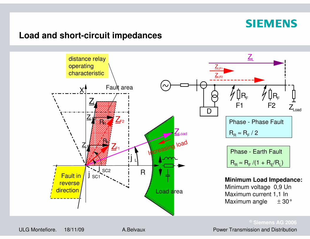
Load and short-circuit impedances
ZL
ZLF1
ZLF2
RF RF
ZLoadDF1 F2
X
R
ZL
ZLF2
j SC1
j SC2
j L
RR
ZF1
ZF2
RR
ZLoad
ZLF1
Fault area
distance relay
operating characteristic
Increasing load
Fault in reverse
direction Load area
Minimum Load Impedance:Minimum voltage 0,9 UnMaximum current 1,1 In
Maximum angle ± 30°
Phase - Phase Fault
RR ≈ RF / 2
Phase - Earth Fault
RR ≈ RF /(1 + RE/RL)

ULG Montefiore. 18/11/09
© Siemens AG 2006
Power Transmission and DistributionA.Belvaux
Graded distance zones
time
D1 D2 D3
t1
t2
t3
Z1
Z2
Z3
distance
∆t = grading time
A CB D
Z1 = 0,85 ZAB
Z2 = 0,85 (ZAB + 0,85 ZBC)
Z3 = 0,85 (ZAB + 0,85 (ZBC + 0,85 ZCD))
Safety margin is 15 %:� line error
� CT, VT error
� measuring error
Grading rules:

ULG Montefiore. 18/11/09
© Siemens AG 2006
Power Transmission and DistributionA.Belvaux
ϕSC
Current area forforward faults
ΙSC
Current area for reverse faults
ΙSC
USC
R
ZSC
Z'SC
Impedance area for forward faults
Impedance area forreverse faults
X
ϕSC
Determination of fault direction
current / voltage diagram impedance diagram
Fault location Where is the fault ?
The impedance also shows the direction, but ....
ULG Montefiore. 18/11/09
© Siemens AG 2006
Power Transmission and DistributionA.Belvaux
X
R
forwards
forw
ards
reverse
reverse
ϕϕϕϕ LoadLoad
Z1
Z2
Z4
Z3
Z1B
Z5
Line
αααα
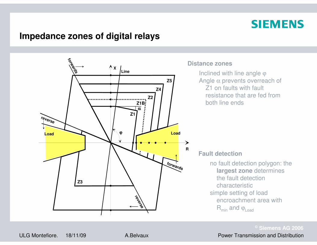
Impedance zones of digital relays
Distance zones
Inclined with line angle ϕ
Angle α prevents overreach of Z1 on faults with fault
resistance that are fed from both line ends
Fault detection
no fault detection polygon: the largest zone determines
the fault detection characteristic
simple setting of load
encroachment area with
Rmin and ϕLoad
ULG Montefiore. 18/11/09
© Siemens AG 2006
Power Transmission and DistributionA.Belvaux
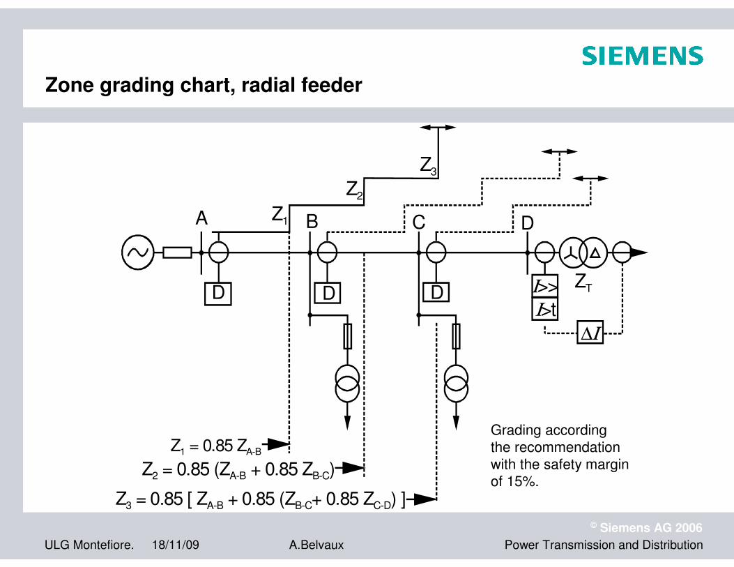
Zone grading chart, radial feeder
D
A
D
B
D
C
Ι>>
D
Ι>t
∆Ι
ZT
Z1
Z2
Z3
Z1 = 0.85 ZA-B
Z3 = 0.85 [ ZA-B + 0.85 (ZB-C+ 0.85 ZC-D) ]
Z2 = 0.85 (ZA-B + 0.85 ZB-C)
Grading according
the recommendation
with the safety margin of 15%.
ULG Montefiore. 18/11/09
© Siemens AG 2006
Power Transmission and DistributionA.Belvaux
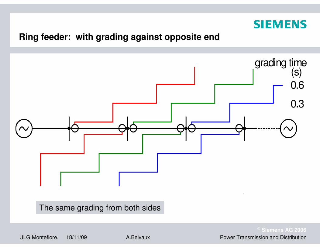
Ring feeder: with grading against opposite end
0.6
0.3
grading time(s)
The same grading from both sides

ULG Montefiore. 18/11/09
© Siemens AG 2006
Power Transmission and DistributionA.Belvaux
Line differential protection
7SD61 / 7SD52
SIPROTEC 4
ULG Montefiore. 18/11/09
© Siemens AG 2006
Power Transmission and DistributionA.Belvaux
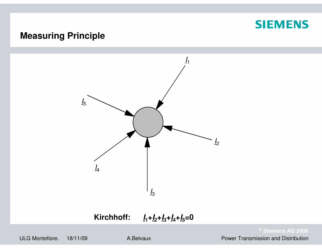
Kirchhoff: I1+I2+I3+I4+I5=0
I1
I2
I3
I4
I5
Measuring Principle

ULG Montefiore. 18/11/09
© Siemens AG 2006
Power Transmission and DistributionA.Belvaux
Trip Characteristic
1:1
(3Y)
1:1
(3Y)
IX
IY
IX
IY
0 6 12 0 6 12
1 p.u. 1 p.u.
Internal Fault

ULG Montefiore. 18/11/09
© Siemens AG 2006
Power Transmission and DistributionA.Belvaux
Trip Characteristic
Internal Fault
IX
IY
0 6 12
0 6 12
3
ID
= IX
+ IY
IR
= IX
+ IY
ID
= (+1)+ (+1) = 2 IR
= +1 + +1 = 2

ULG Montefiore. 18/11/09
© Siemens AG 2006
Power Transmission and DistributionA.Belvaux
Idiff
Istab
fault line (k=1)
internal fault
external fault oroperation condition
Ideal internal fault
� Idiff = I1
� Istab = I1
� fault is on fault line
External fault
� Idiff = 0
� Istab = |I1|+|I2|+...|In|
security for CT deviations
Trip Characteristic
ULG Montefiore. 18/11/09
© Siemens AG 2006
Power Transmission and DistributionA.Belvaux
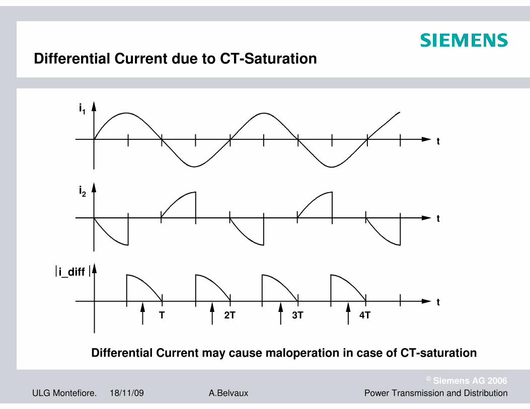
Differential Current may cause maloperation in case of CT-saturation
i1
i2
i_diff
T 2T 3T 4T
t
t
t
Differential Current due to CT-Saturation

ULG Montefiore. 18/11/09
© Siemens AG 2006
Power Transmission and DistributionA.Belvaux
Current transformer saturation
Saturation during steady-state current
Saturation during offset current

ULG Montefiore. 18/11/09
© Siemens AG 2006
Power Transmission and DistributionA.Belvaux
Line differential protectionLine differential protection
SIPROTEC 4
� Current Comparison Protection for all
applications for cables and overhead
lines
� Two up to six line ends
� Handles transformers in the protected
zone (integrated vector group matching)
� Direct connection to communication
networks
� Communication via copper and ISDN
networks
� Fault Locator
� Fast tripping (less than 15 ms)
� Automatic reclosure
ULG Montefiore. 18/11/09
© Siemens AG 2006
Power Transmission and DistributionA.Belvaux
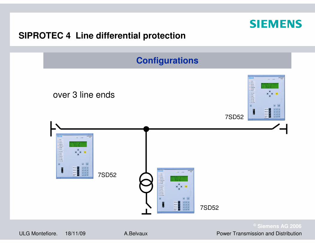
over 3 line ends
7SD52
7SD52
7SD52
SIPROTEC 4 Line differential protection
ConfigurationsConfigurations
ULG Montefiore. 18/11/09
© Siemens AG 2006
Power Transmission and DistributionA.Belvaux
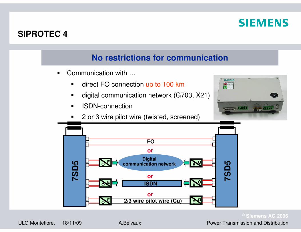
� direct FO connection up to 100 km
� digital communication network (G703, X21)
� ISDN-connection
� 2 or 3 wire pilot wire (twisted, screened)
Digitalcommunication network
or7S
D5
ISDN
or2/3 wire pilot wire (Cu)
FO
or
7S
D5O
EE
O
EO
EO
OE
OE
No restrictions for communicationNo restrictions for communication
� Communication with …
SIPROTEC 4

ULG Montefiore. 18/11/09
© Siemens AG 2006
Power Transmission and DistributionA.Belvaux
Multifunctional Protectionfor
Transformers and Generators 7UT6
SIPROTEC 4

ULG Montefiore. 18/11/09
© Siemens AG 2006
Power Transmission and DistributionA.Belvaux
Measuring Preprocessing, Example for CT Matching (Part 1)
IP1 = 500A(load current)
IP2 = 1833A(load current)
1000/5A 2000/5A
UN1 = 110kV UN2 = 30kV
SN = 100MVA
winding 1 winding 2
7UT512
IDiff = ? IStab= ?
IN, Trafo = 525A IN, Trafo = 1924A
IS1 = 2.5A IS2 = 4.58Ameasuredsecondary currents
ULG Montefiore. 18/11/09
© Siemens AG 2006
Power Transmission and DistributionA.Belvaux
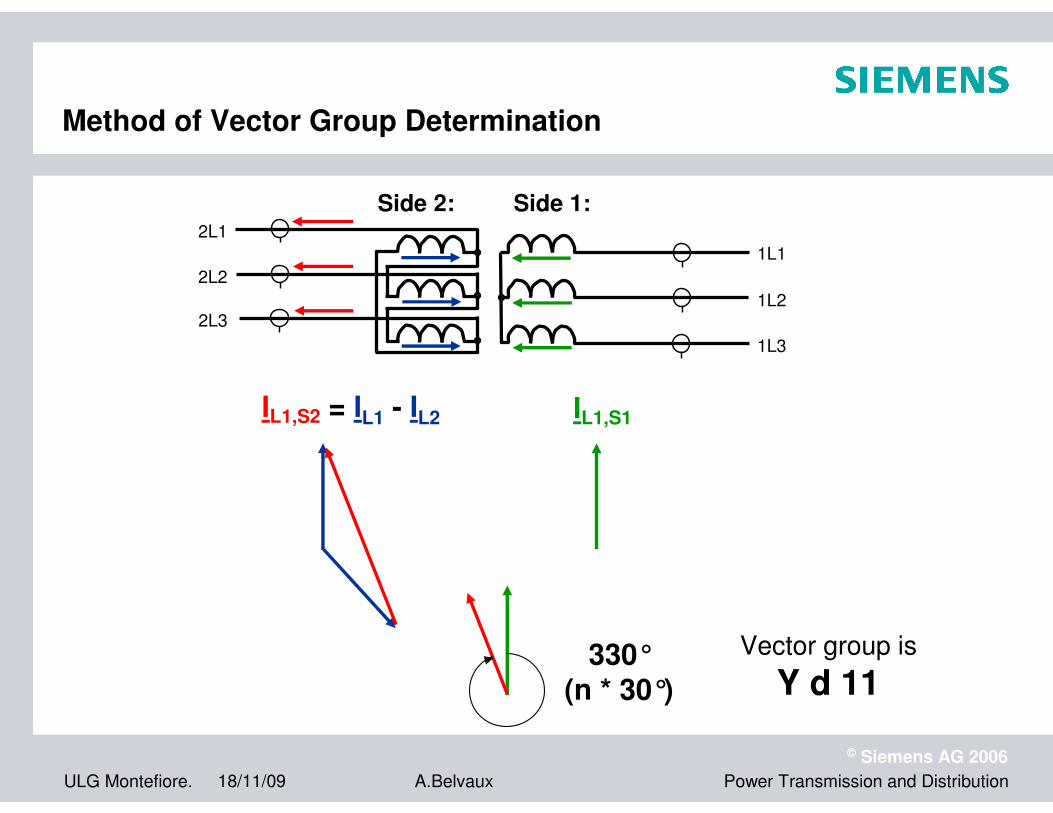
Method of Vector Group Determination
IL1,S1IL1,S2 = IL1 - IL2
330°(n * 30°)
Vector group is
Y d 11
Side 2: Side 1:
1L1
1L2
1L3
2L1
2L2
2L3

ULG Montefiore. 18/11/09
© Siemens AG 2006
Power Transmission and DistributionA.Belvaux
Smart grids : a definition
A smart grid is an electricity network that can intelligently integrate the actions of all users connected to it� generators � consumers � and those that do both
in order to efficiently deliver
sustainable, economic and secure electricity supply

ULG Montefiore. 18/11/09
© Siemens AG 2006
Power Transmission and DistributionA.Belvaux
Transmission networks are not ‘un-smart’
Network� Network under central control and command (SCADA, congestion
management, balancing, defence plans ...)� Control of bidirectional flows (metering, protections,...)� Coordination of the power plants operation� Wide Area Measurement Systems (WAMS) at pan-European level
IT� Centralized quarter-hourly metering systems� Telecom IP systems, connecting all sub-stations
Market mechanisms� Management of area control in real-time with web publication� Management of ancillary services (power reserves)� Explicit and implicit auctions of cross border transmission capacities
(Belpex) , nomination systems, specific pricing for local generation� « Central-West Europe » Region (flow-based market, ...)
ULG Montefiore. 18/11/09
© Siemens AG 2006
Power Transmission and DistributionA.Belvaux
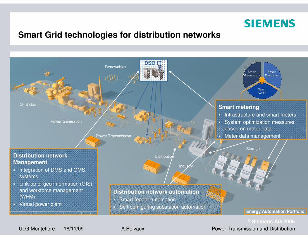
DSO IT
Distribution networkManagement
� Integration of DMS and OMS
systems
� Link-up of geo information (GIS)
and workforce management
(WFM)
� Virtual power plant
Distribution network automation
� Smart feeder automation
� Self-configuring substation automation
Smart metering
� Infrastructure and smart meters
� System optimization measures
based on meter data
� Meter data management
Smart Grid technologies for distribution networks
Energy Automation Portfolio
Renewables
Storage
Power Transmission
Industry
Distribution
Oil & Gas
Power Generation

ULG Montefiore. 18/11/09
© Siemens AG 2006
Power Transmission and DistributionA.Belvaux
Vision of European Union