Embed Size (px)
Citation preview
ENE 104
Electric Circuit Theory
Lecture 09:
Sinusoidal Steady-State Analysis
http://webstaff.kmutt.ac.th/~dejwoot.kha/
(ENE) Mon, 12 Mar 2012 / (EIE) Wed, 21 Mar 2012
Week #10 : Dejwoot KHAWPARISUTH

Objectives : Ch10
Week #10
Page 2
ENE 104
• sinusoidal functions
• impedance and admittance
• use phasors to determine the forced response of
a circuit subjected to sinusoidal excitation
• Apply techniques using phasors
Sinusoidal Steady-State Analysis

Introduction: Page 3
The sinusoidal function v(t) = Vm sin wt is plotted
(a) versus wt and (b) versus t.
Characteristics of Sinusoids
tVtv m wsin)(
Tf
1 w 2T fw 2
Week #10 ENE 104 Sinusoidal Steady-State Analysis

Lagging and leading: Page 4
The sine wave Vm sin (wt + q) leads Vm sin wt by q rad.
Week #10 ENE 104 Sinusoidal Steady-State Analysis

Lagging and leading: Page 5
Converting Sines to Cosines
)1005sin(
)10905sin(
)105cos(
1
1
11
+
++
+
tV
tV
tVv
m
m
m
)305sin(22 tVv m
Week #10 ENE 104 Sinusoidal Steady-State Analysis
In electrical engineering, the phase angle is commonly given in degrees, rather than radian.

Lagging and leading: Page 6
Week #10 ENE 104 Sinusoidal Steady-State Analysis
Two sinusoidal waves whose phase are to be
compared must:
1. Both be written as sine waves, or both as
cosine waves.
2. Both be written with positive amplitudes.
3. Each have the same frequency.
Normally, the difference in phase between two
sinusoids is expressed by that angle which is
less than or equal to 180 degree in magnitude

Practice: 10.1 Page 7
Week #10 ENE 104 Sinusoidal Steady-State Analysis
Find the angle by which 𝑖1 lags 𝑣1 if
𝑣1 = 120cos(120𝜋𝑡 − 40𝑜) V and 𝑖1 equals
(a) 2.5 cos 120𝜋𝑡 + 20𝑜 A; (b) 1.4 𝑠𝑖𝑛 120𝜋𝑡 − 70𝑜 A;
(c) Acos 100𝑡 + 𝐵𝑠𝑖𝑛100𝑡 = 𝐶𝑐𝑜𝑠(100𝑡 +𝜙).

Practice: 10.2 Page 8
Week #10 ENE 104 Sinusoidal Steady-State Analysis
Find A, B, C, and 𝜙 if 40 cos 100𝑡 − 40° −20 sin 100𝑡 + 170° = 𝐴𝑐𝑜𝑠100𝑡 + 𝐵𝑠𝑖𝑛100𝑡 =𝐶𝑐𝑜𝑠(100𝑡 + 𝜙).

Practice: 10.2 Page 9
Week #10 ENE 104 Sinusoidal Steady-State Analysis

Forces Response: Page 10
Forces Response to sinusoidal Functions:
The Steady-State Response
tVRidt
diL m wcos+
Week #10 ENE 104 Sinusoidal Steady-State Analysis
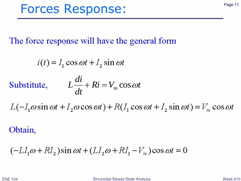
Forces Response: Page 11
tVRidt
diL m wcos+
Week #10 ENE 104 Sinusoidal Steady-State Analysis
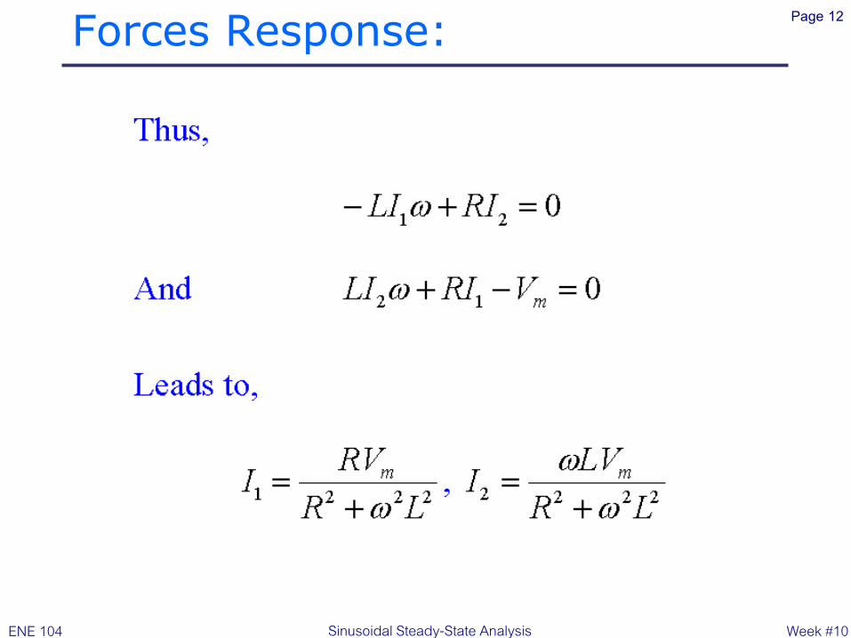
Forces Response: Page 12
Week #10 ENE 104 Sinusoidal Steady-State Analysis
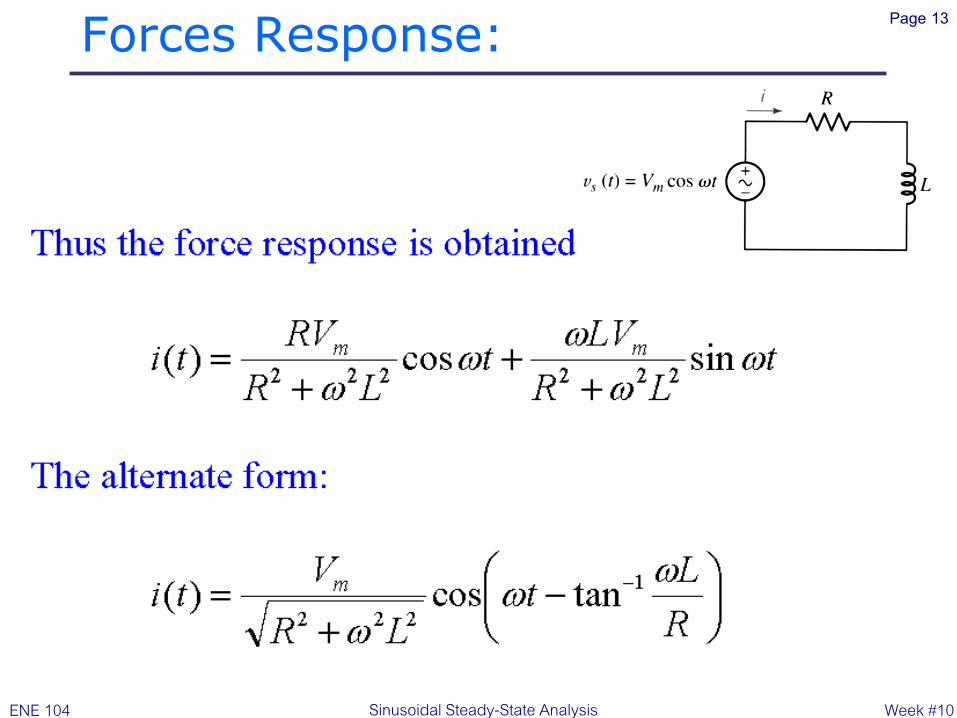
Forces Response: Page 13
Week #10 ENE 104 Sinusoidal Steady-State Analysis

Example: Page 14
Find the current Li
Week #10 ENE 104 Sinusoidal Steady-State Analysis

Example: Page 15
Find the current Li
) )
) .3.5610cos222
20
103010tan10cos
10301020
8
tancos)(
3
3313
2332
1
222
mAt
t
R
Lt
LR
Vti m
+
+
ww
w
Week #10 ENE 104 Sinusoidal Steady-State Analysis

Practice: 10.3 Page 16
Week #10 ENE 104 Sinusoidal Steady-State Analysis
Let 𝑣𝑠 = 40𝑐𝑜𝑠8000𝑡 V in the circuit. Use Thevenin’s
theorem where it will do the most good, and find the
value at t = 0 for (a) 𝑖𝐿; (b) 𝑣𝐿; (c) 𝑖𝑅; (d) 𝑖𝑠
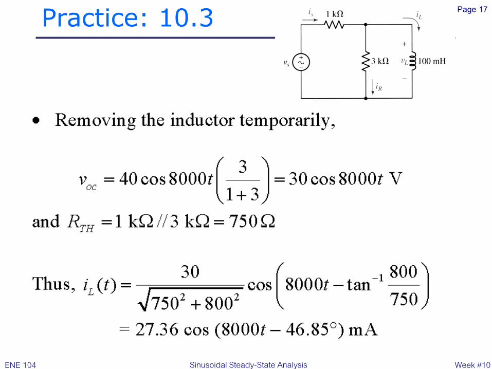
Practice: 10.3 Page 17
Week #10 ENE 104 Sinusoidal Steady-State Analysis

Practice: 10.3 Page 18
Week #10 ENE 104 Sinusoidal Steady-State Analysis

The Complex Forcing Fn: Page 19
Week #10 ENE 104 Sinusoidal Steady-State Analysis
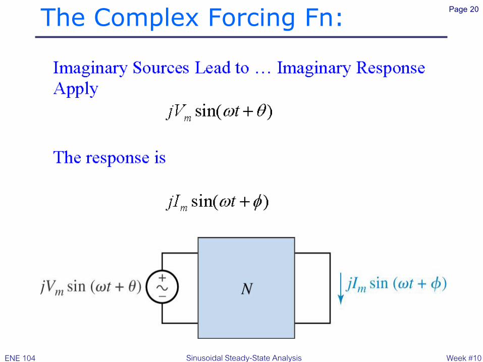
The Complex Forcing Fn: Page 20
Week #10 ENE 104 Sinusoidal Steady-State Analysis

The Complex Forcing Fn: Page 21
Week #10 ENE 104 Sinusoidal Steady-State Analysis

The Complex Forcing Fn: Page 22
Week #10 ENE 104 Sinusoidal Steady-State Analysis
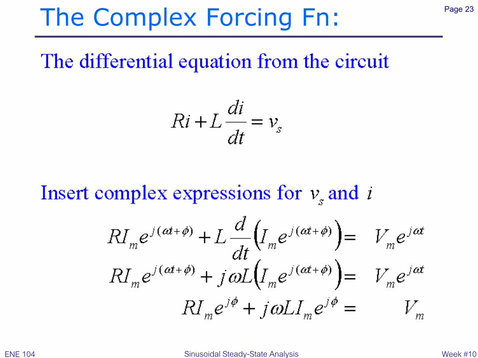
The Complex Forcing Fn: Page 23
Week #10 ENE 104 Sinusoidal Steady-State Analysis
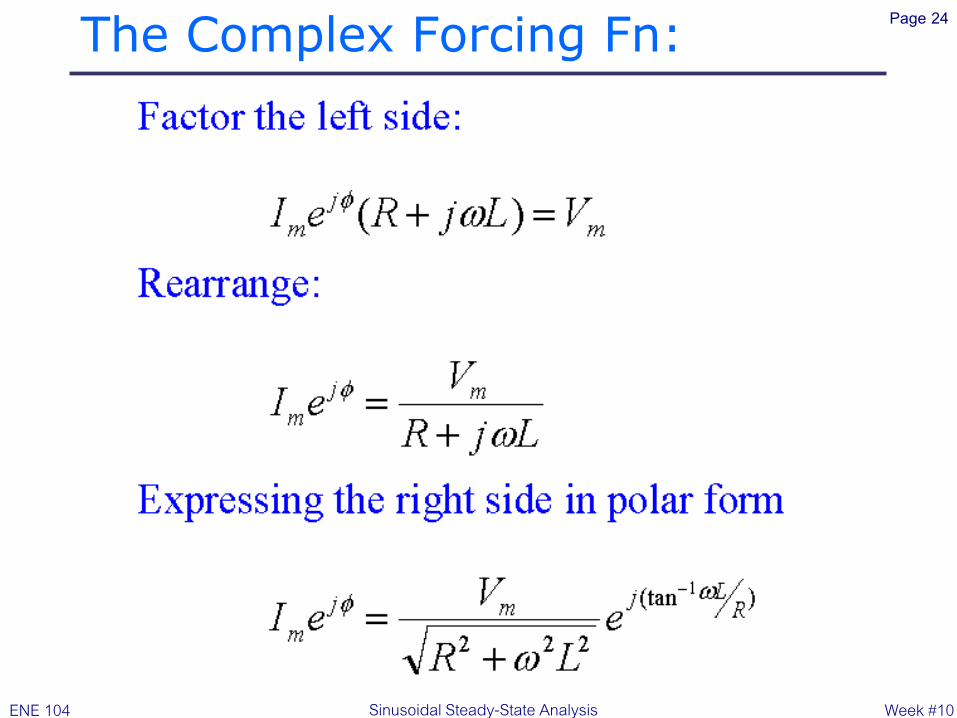
The Complex Forcing Fn: Page 24
Week #10 ENE 104 Sinusoidal Steady-State Analysis
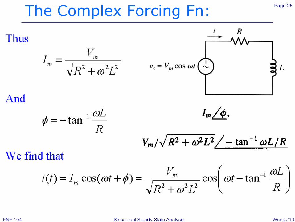
The Complex Forcing Fn: Page 25
Week #10 ENE 104 Sinusoidal Steady-State Analysis

Practice: 10.4 Page 26
Week #10 ENE 104 Sinusoidal Steady-State Analysis
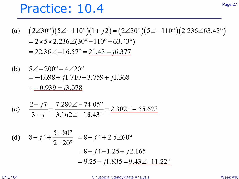
Evaluate and express the result in rectangular form:
(a) 2∠30° 5∠ − 110° 1 + 2𝑗 ; (b) 5∠ − 200° +4∠20°. Evaluate and express the result in polar form: (c)
(2 − 𝑗7)/(3 − 𝑗); (d) 8 − 𝑗4 + 5∠80° / 2∠20° .
Practice: 10.4 Page 27
Week #10 ENE 104 Sinusoidal Steady-State Analysis
Practice: 10.5 Page 28
Week #10 ENE 104 Sinusoidal Steady-State Analysis
If the use of the passive sign convention is
specified, find the (a) complex voltage that
results when the complex current 4𝑒𝑗800𝑡 A is
applied to the series combination of a 1-mF
capacitor and a 2-Ω resistor; (b) complex current
that results when the complex voltage100𝑒𝑗2000𝑡 V is applied to the parallel combination of a 1-mH
inductor and a 50-Ω resistor.

Practice: 10.5 Page 29
Week #10 ENE 104 Sinusoidal Steady-State Analysis

Practice: 10.5 Page 30
Week #10 ENE 104 Sinusoidal Steady-State Analysis

The Phasor: Page 31
A phasor transformation:
0)cos()( mm VtVtv w
w + mm ItIti )cos()(
Week #10 ENE 104 Sinusoidal Steady-State Analysis
Practice: 10.6 Page 32
Week #10 ENE 104 Sinusoidal Steady-State Analysis
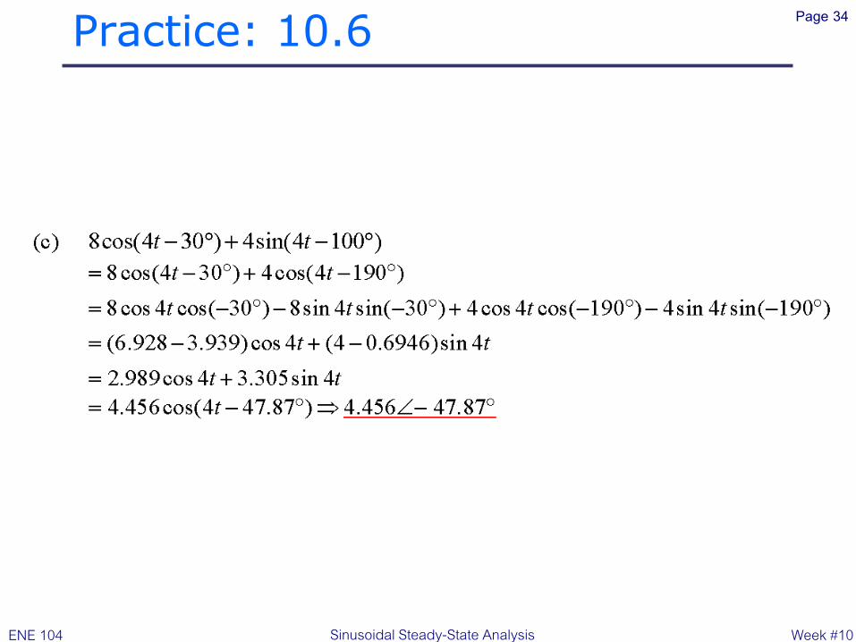
Transform each of the following functions of time
into phasor form: (a) −5sin(580𝑡 − 110°); (b)
3cos600t − 5sin(600𝑡 + 110°); (c)8𝑐𝑜 𝑠 4𝑡 − 30° +4sin(4𝑡 − 100°). Hint: First convert each into a single cosine function
with a positive magnitude

Practice: 10.6 Page 33
Week #10 ENE 104 Sinusoidal Steady-State Analysis
Practice: 10.6 Page 34
Week #10 ENE 104 Sinusoidal Steady-State Analysis

Practice: 10.7 Page 35
Week #10 ENE 104 Sinusoidal Steady-State Analysis
Let 𝜔 = 2000 rad/s and t = 1 ms. Find the
instantaneous value of each of the currents given
here in phasor form: (a) 𝑗10 A; (b) 20 + 𝑗10 A; (c)
20 + 𝑗(10∠20°) A.

Practice: 10.7 Page 36
Week #10 ENE 104 Sinusoidal Steady-State Analysis

Phasor Relationship: Page 37
Week #10 ENE 104 Sinusoidal Steady-State Analysis
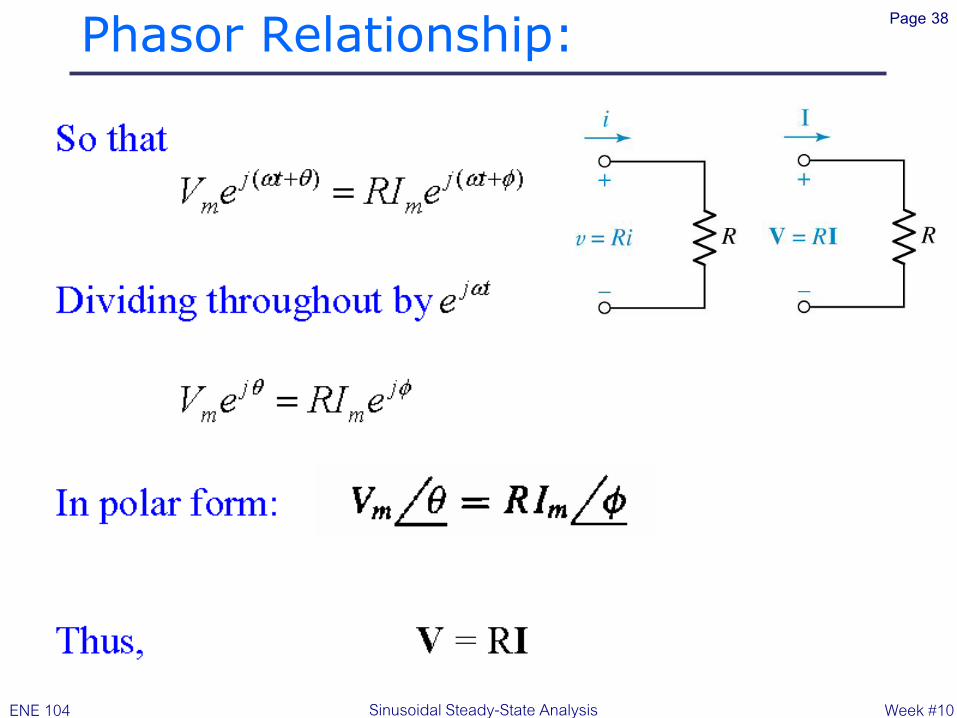
Phasor Relationship: Page 38
Week #10 ENE 104 Sinusoidal Steady-State Analysis

Phasor Relationship: Page 39
Week #10 ENE 104 Sinusoidal Steady-State Analysis

Phasor Relationship: Page 40
The Capacitor: dt
dvCti )(
Week #10 ENE 104 Sinusoidal Steady-State Analysis

Phasor Relationship: Page 41
Week #10 ENE 104 Sinusoidal Steady-State Analysis

Phasor Relationship: Page 42
Week #10 ENE 104 Sinusoidal Steady-State Analysis

Phasor: Page 43
Week #10 ENE 104 Sinusoidal Steady-State Analysis
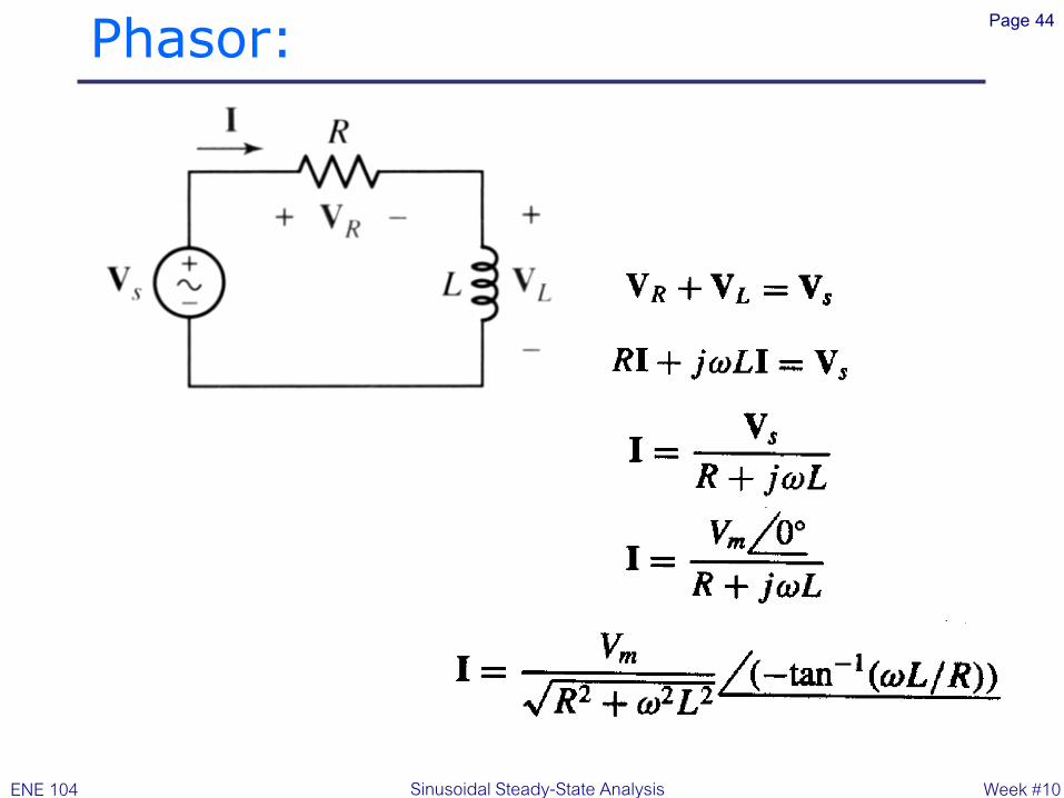
Phasor: Page 44
Week #10 ENE 104 Sinusoidal Steady-State Analysis

Practice: 10.8 Page 45
Week #10 ENE 104 Sinusoidal Steady-State Analysis
In the circuit, let 𝜔 = 1200 rad/s, 𝐈𝐶 = 1.2∠28° A,
and 𝐈𝐿 = 3∠53° A. Find (a) 𝐈𝒔; (b) 𝐕𝒔; (c) 𝑖𝑅(𝑡).

Practice: 10.8 Page 46
Week #10 ENE 104 Sinusoidal Steady-State Analysis

Impedance: Z Page 47
A resistance
A reactance
Week #10 ENE 104 Sinusoidal Steady-State Analysis

Practice: 10.9 Page 48
Week #10 ENE 104 Sinusoidal Steady-State Analysis
With reference to the network shown, find the input
impedance 𝐙𝑖𝑛 that would be measured between
terminals: (a) a and g; (b) b and g; (c) a and b

Practice: 10.9 Page 49
Week #10 ENE 104 Sinusoidal Steady-State Analysis

Example: find i(t) Page 50
9040)903000cos(40)3000sin(40 tt
kj
jLj
13
13000w
kj
j
Cj
26
13000
1
w
Week #10 ENE 104 Sinusoidal Steady-State Analysis

Example: Page 51
+
+
+
kj
jj
jjZtotal
87.365.25.12
21
)21()(5.1
.9.12616.87.365.2
9040mAmA
Z
VI
total
s
.)9.1263000cos(16 mAt
Week #10 ENE 104 Sinusoidal Steady-State Analysis
Practice: 10.10 Page 52
Week #10 ENE 104 Sinusoidal Steady-State Analysis
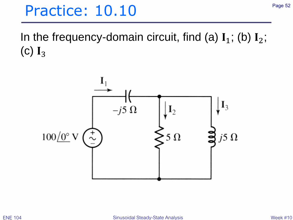
In the frequency-domain circuit, find (a) 𝐈1; (b) 𝐈2;
(c) 𝐈3

Practice: 10.10 Page 53
Week #10 ENE 104 Sinusoidal Steady-State Analysis
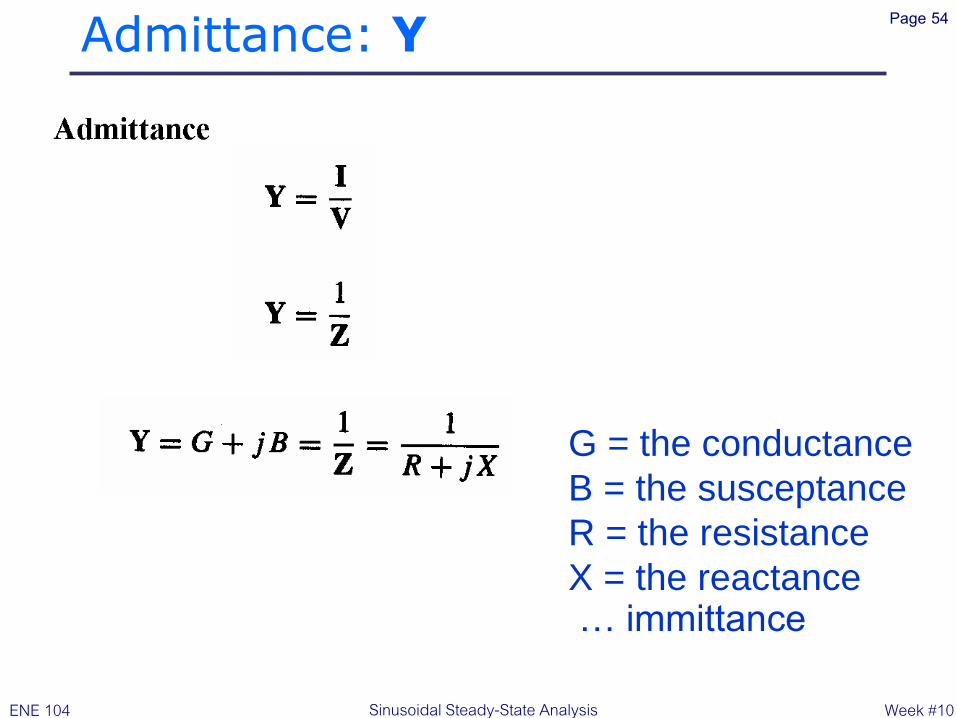
Admittance: Y Page 54
G = the conductance
B = the susceptance
R = the resistance
X = the reactance … immittance
Week #10 ENE 104 Sinusoidal Steady-State Analysis

Practice: 10.11 Page 55
Determine the admittance (in rectangular form)
of (a) an impedance 𝐙 = 1000 + 𝑗400 ; (b) a
network consisting of the parallel combination of
an 800- resistor, a 1-mH inductor, and a 2-nF
capacitor, if 𝜔 = 1 Mrad/s; (c) a network
consisting of the series combination of an 800-
resistor, a 1-mH inductor, and a 2-nF capacitor, if
𝜔 = 1 Mrad/s
Week #10 ENE 104 Sinusoidal Steady-State Analysis

Practice: 10.11 Page 56
Week #10 ENE 104 Sinusoidal Steady-State Analysis

Nodal and Mesh Analysis: Page 57
Example: find v1(t) and v2(t)
0101105105
212111 jj
VV
j
VV
j
VV+
+
+
+
5.0)05.0(105105
221212 jV
j
V
j
VV
j
VV++
+
Week #10 ENE 104 Sinusoidal Steady-State Analysis

Practice: 10.12 Page 58
Week #10 ENE 104 Sinusoidal Steady-State Analysis
Use nodal analysis on the circuit to find 𝐕1 and 𝐕2.

Practice: 10.12 Page 59
Week #10 ENE 104 Sinusoidal Steady-State Analysis

Nodal and Mesh Analysis: Page 60
Example: find I1 and I2
09015)(3)(5010 211 +++ IIIj
0020)(4)(39015 212 ++ IjII
Week #10 ENE 104 Sinusoidal Steady-State Analysis

'
1V '
2V
Superposition: Page 61
Example: find V1
''
1V''
2V
Week #10 ENE 104 Sinusoidal Steady-State Analysis

'
1V '
2V
Superposition: Page 62
Example: find V1
5561.01951.0
2540
)25()40(50
20'
1
j
j
jj
Y
IV
+
Week #10 ENE 104 Sinusoidal Steady-State Analysis
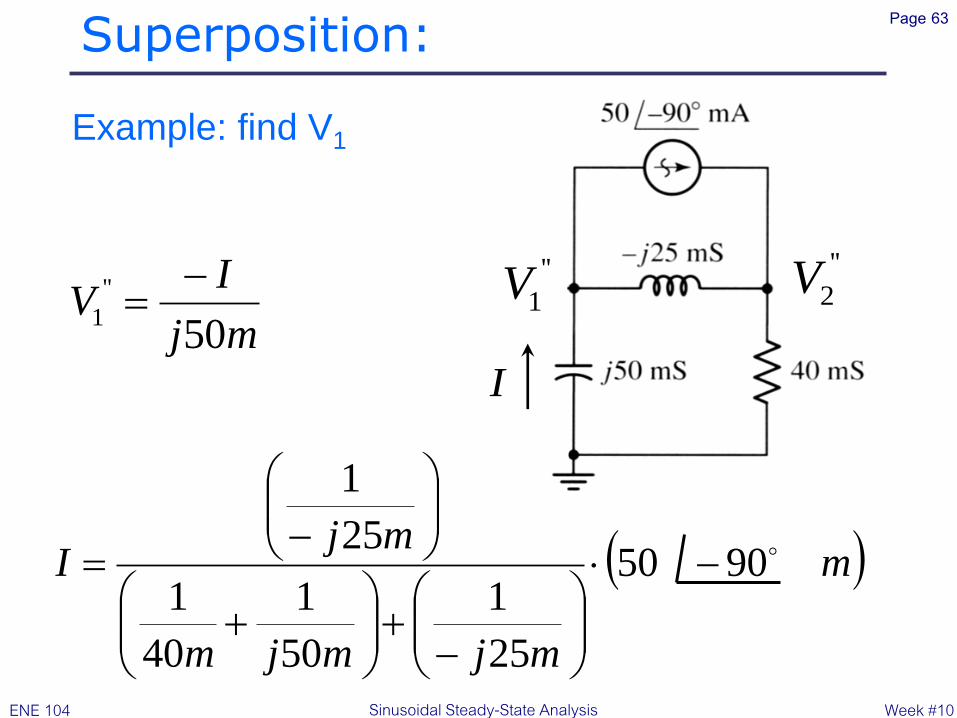
Superposition: Page 63
Example: find V1
''
1V''
2V
I
mj
IV
50
''
1
)m
mjmjm
mjI 9050
25
1
50
1
40
1
25
1
+
+
Week #10 ENE 104 Sinusoidal Steady-State Analysis
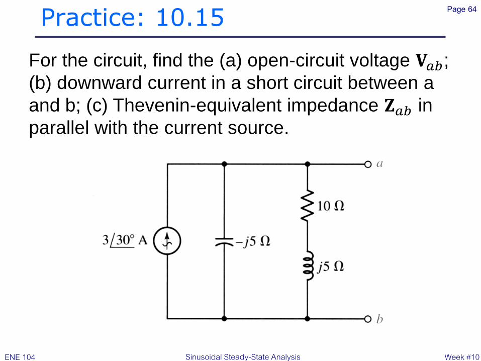
Practice: 10.15 Page 64
Week #10 ENE 104 Sinusoidal Steady-State Analysis
For the circuit, find the (a) open-circuit voltage 𝐕𝑎𝑏;
(b) downward current in a short circuit between a
and b; (c) Thevenin-equivalent impedance 𝐙𝑎𝑏 in
parallel with the current source.

Practice: 10.15 Page 65
Week #10 ENE 104 Sinusoidal Steady-State Analysis

Practice: 10.16 Page 66
Determine the current 𝑖 through the 4- resistor
Week #10 ENE 104 Sinusoidal Steady-State Analysis

Practice: 10.16 Page 67
Week #10 ENE 104 Sinusoidal Steady-State Analysis

Phasor Diagram: Page 68
1.5310861 + jV
Week #10 ENE 104 Sinusoidal Steady-State Analysis

Phasor Diagram: Page 69
(a) A phasor diagram showing the
sum of V1 = 6 + j8 V and V2 = 3
– j4 V, V1 + V2 = 9 + j4 V =
9.8524.0o V.
(b) (b) The phasor diagram shows
V1 and I1, where I1 = YV1 and Y
= 1 + j S = 1.445o S. The
current and voltage amplitude
scales are different.
Week #10 ENE 104 Sinusoidal Steady-State Analysis

Phasor Diagram: Page 70
Week #10 ENE 104 Sinusoidal Steady-State Analysis

Phasor Diagram: Page 71
Week #10 ENE 104 Sinusoidal Steady-State Analysis
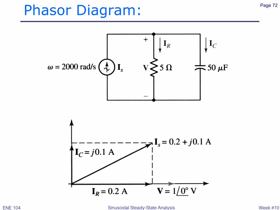
Phasor Diagram: Page 72
Week #10 ENE 104 Sinusoidal Steady-State Analysis

Example: Page 73
Select V =
; IR =
IL = IC =
01
01)2.0(
901.001)1.0( j
903.001)3.0( j
Week #10 ENE 104 Sinusoidal Steady-State Analysis

Example: Page 74
Week #10 ENE 104 Sinusoidal Steady-State Analysis

Practice: 10.17 Page 75
Week #10 ENE 104 Sinusoidal Steady-State Analysis
Select some convenient reference value for 𝐈𝐶 in
the circuit, draw a phasor diagram showing 𝐕𝑅,
𝐕2, 𝐕1, and 𝐕𝑠, and measure the ratio of the
lengths of (a) 𝐕𝑠 to 𝐕1; (b) 𝐕1 to 𝐕2; (c) 𝐕𝑠 to 𝐕R
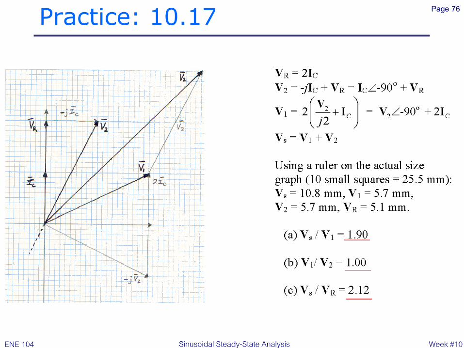
Practice: 10.17 Page 76
Week #10 ENE 104 Sinusoidal Steady-State Analysis
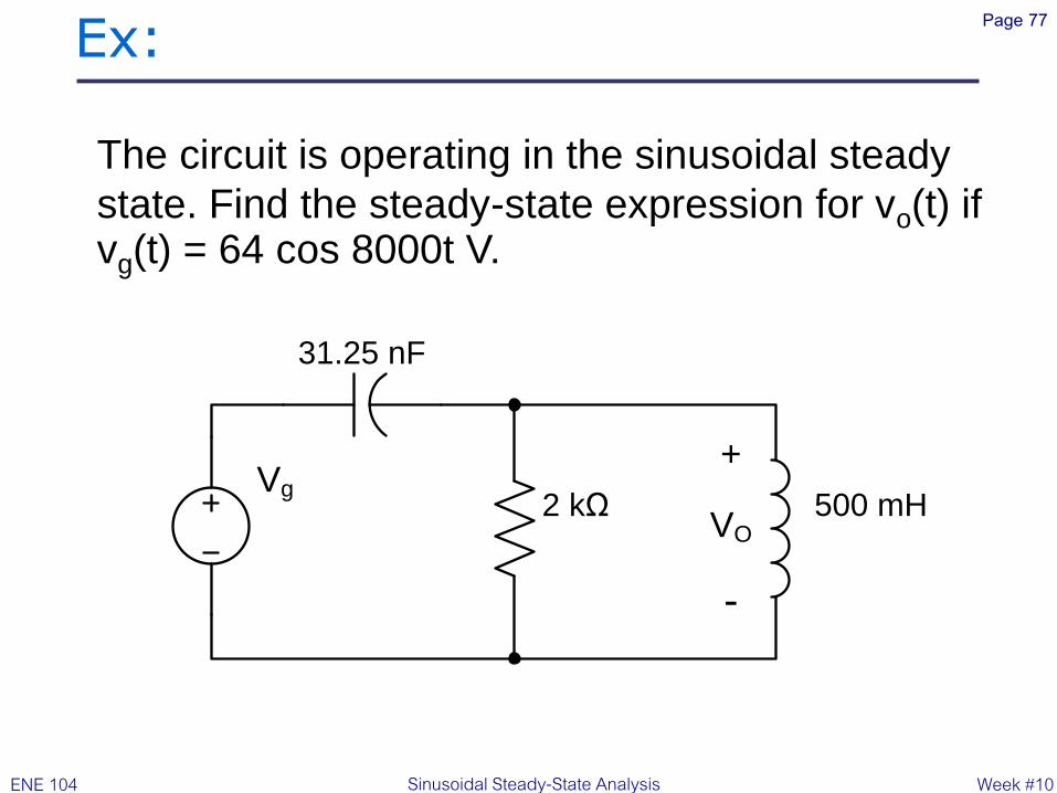
Ex: Page 77
31.25 nF
2 kΩVg
500 mHVO
+
-
The circuit is operating in the sinusoidal steady
state. Find the steady-state expression for vo(t) if vg(t) = 64 cos 8000t V.
Week #10 ENE 104 Sinusoidal Steady-State Analysis

Ex: Page 78
Week #10 ENE 104 Sinusoidal Steady-State Analysis

Hw: Page 79
Week #10 ENE 104 Sinusoidal Steady-State Analysis

Reference: Page 80
W.H. Hayt, Jr., J.E. Kemmerly, S.M. Durbin, Engineering Circuit Analysis, Sixth Edition.
Copyright ©2002 McGraw-Hill. All rights reserved.
Circuit Analysis and Electrical Engineering