Embed Size (px)
Citation preview

ENDURANCE LIMIT OF ALUMINUM, BRASS AND MILD STEEL ON DIFFERENT SURFACE FINISH OWING TO CYCLIC LOADS
AHMAD FITRI BIN ZAINAL ABIDIN
Thesis submitted in fulfilment of the requirements for the award of the degree of
Bachelor of Mechanical Engineering
Faculty of Mechanical EngineeringUNIVERSITI MALAYSIA PAHANG
NOVEMBER 2009

STUDENT’S DECLARATION
I hereby declare that the work in this project is my own except for quotations and
summaries which have been duly acknowledged. The project has not been accepted for
any degree and is not concurrently submitted for award of other degree.
Signature :
Name : AHMAD FITRI BIN ZAINAL ABIDIN
I.D Number : MA06044
Date :

Dedicated to my parents, my supervisor, all my friends and Elianez Binti Abu
Shuja
ACKNOWLEDGEMENT
First and foremost, grateful to Allah SWT for making it possible for me to complete this project on time. I am grateful and would like to express my sincere gratitude to my supervisor Mr. Lee Giok Chui SMN., KMN for his germinal ideas, invaluable guidance, continuous encouragement and constant support in making this research possible. I appreciate his consistent support from the first day I applied to graduate program to these concluding moments. I also sincerely thanks for the time spent proofreading and correcting my many mistakes.
My sincere thanks go to all my classmates and members of the staff of the Mechanical Engineering Department, UMP, who helped me in many ways and made my stay at UMP pleasant and unforgettable.
I acknowledge my sincere indebtedness and gratitude to my parents for their love, dream and sacrifice throughout my life. I cannot find the appropriate words that could properly describe my appreciation for their devotion, support and faith in my ability to attain my goals.
ABSTRACT
The investigation is about the endurance limit of aluminum, brass and mild steelthat has been done at the surface of the specimens on different surface roughness. The endurance limit of the specimens have been determined by testing under different loads on the fatigue testing machine and the life cycles of each specimens has been taken after crack occur on the specimen. Endurance limit is defined as the alternating stress that causes failures after some specified number of cycles. This study or investigation has the steps that is starting form the fabrication on different surface roughness, testing on the fatigue machine and gather all the data to compare the results.. The different surface roughness will give different life cycles. Then, comparison of the result needs to be done to get the best materials on different surface roughness to create a good choosing of materials in industry. Finally, studies of Endurance limit or fatigue strength can still be expanded and widened due to the other properties that can be tested such as curvature radii and elongation of the materials due to a break point.
ABSTRAK
Kajian ini mengenai had daya ketahanan aluminium, tembaga dan besi lembut dan kajian dijalankan diatas permukaan spesimen berdasarkan perbezaan kekasaran permukaan.Daya ketahanan setiap spesimen diuji dengan daya yang berbeza-beza di mesin ketahanan bahan.dan putaran hidup setiap bahan selepas keretakan berlaku.Daya ketahanan bermaksud bahan yang diuji tidak putus atau retak selepas dikenakan daya untuk beberapa putaran hidup. Pembelajaran dan kajian ini mempunyai beberapa tahap bermula dengan membina bahan untuk membolehkan ia dimasukkan didalam mesin, seterusnya diuji didalam mesin daya tahan dan seterusnya data diambil untuk membuat perbandingan untuk memilih bahan yang terbaik didalam industri.Yang terakhir, kajian mengenai had ketahanan setiap bahan boleh diperluaskan dengan kajian perbezaan melalui jejari setiap bahan dan kepanjangan bahan.
TABLE OF CONTENTS
Page
SUPERVISOR’S DECLARATION ii
STUDENT’S DECLARATION iii
ACKNOWLEDGEMENTS v
ABSTRACT vi
ABSTRAK vii
TABLE OF CONTENTS viii
LIST OF TABLES xi
LIST OF FIGURES xii
LIST OF SYMBOLS xiv
LIST OF ABBREVIATIONS xv
CHAPTER 1 INTRODUCTION
1.1 Project Background 1
1.2 Problem Statements 2
1.3 Objective of Research 3
1.4 Scopes 3
CHAPTER 2 LITERATURE REVIEW
2.1 Fatigue 4
2.2 Fatigue Strength 5
2.3
2.4
Fatigue Strength Testing
Fatigue Damage Process
6
6
2.5
2.6
2.7
2.8
2.9
2.10
2.11
Fatigue Failure
Endurance Limit
Factors Influencing Fatigue Life
Improving Fatigue Strength
Design against Fatigue
S-N Curves 2.10.1 Calculation of Stress 2.10.2 Calculation of the Specimen
Previous Research Study
8
11
12
13
14
151717
18
CHAPTER 3 METHODOLOGY
3.1 Introduction 20
3.2
3.3
3.4
Processing Flow
Specimen Preparation
Cutting Specimen
21
22
23
3.5 Experiment Method 23
3.6 Surface Roughness Measurement 3.6.1 Experiment Procedure
2424
3.7 Fatigue Testing 3.7.1 Fatigue Tester 3.7.2 Test Instruction
252526
3.8 Interpolating S-N Curves 27
CHAPTER 4 RESULTS AND DISCUSSION
4.1 Endurance Limit Analysis 28
4.2
4.3
Testing Result
Testing Under Different Surface Roughness
29
30
4.4 Discussion of Comparison on Endurance of materials 32
4.5 Graphs For Aluminum, Brass and Mild Steel on
Different Surface Roughness
33
4.6 Discussion From Graph 45

CHAPTER 5 CONCLUSION AND RECOMMENDATIONS
5.1 Conclusions 46
5.2 Recommendations 47
REFERENCES 48
APPENDICES
A Gantt Chart FYP 1 and FYP 2
B Technical Drawing
49
51
LIST OF TABLE
Table No Title Page
3.1 Number of Specimen 22
3.2 Parameters for cutting Materials 23
4.1 Data of stress and life cycle of Aluminum (2570 rpm) 30
4.2 Data of stress and life cycle of Aluminum (990 rpm) 30
4.3 Data of stress and life cycle of Aluminum (100 rpm) 30
4.4 Data of stress and life cycle of Brass (2570 rpm) 30
4.5 Data of stress and life cycle of Brass (990 rpm) 31
4.6 Data of stress and life cycle of Brass (100 rpm) 31
4.7 Data of stress and life cycle of Mild Steel (2570 rpm) 31
4.8 Data of stress and life cycle of Mild Steel (990 rpm) 31
4.9 Data of stress and life cycle of Mild Steel (100 rpm) 31
LIST OF FIGURES
Figure No Title Page
2.1 Life Cycle of 1045 Steel and 2014-T6 Al 7
2.2 S-N Curve Approximation 8
2.3 Fatigue failure on a crankshaft 10
2.4 Fracture of a bolt 11
2.5 Curves of applied stress Vs number of cycles of steel and aluminum 12
2.6 Example of Brittle Aluminum S-N Curves 18
3.1 Processing Flow 21
3.2 Dimension of the Specimen 22
3.3 Conventional Lathe Machine 23
3.4 Perthometer 24
3.5 Fatigue Tester Machine 25
4.1 Picture of specimen before experiment 29
4.2 Picture of specimen after experiment 29
4.3 S-N Curves For Aluminum ( 2570 RPM ) 33
4.4 S-N Curves For Aluminum ( 990 RPM ) 34
4.5 S-N Curves For Aluminum ( 100 RPM ) 35
4.6 S-N Curves For Brass ( 2570 RPM ) 36
4.7 S-N Curves For Brass ( 990 RPM ) 37
4.8 S-N Curves For Brass ( 100 RPM ) 38
4.9 S-N Curves For Mild Steel ( 2570 RPM ) 39

4.10 S-N Curves For Mild Steel ( 990 RPM ) 40
4.11 S-N Curves For Mild Steel ( 100 RPM ) 41
4.12 S-N Curves For Aluminum on Different Surface Roughness 42
4.13 S-N Curves For Brass on Different Surface Roughness 43
4.14 S-N Curves For Mild Steel on Different Surface Roughness 44
LIST OF SYMBOLS
r radius
Rpm radius per minute
N Newton
Σ stress
N Life cycles or endurance
Sf Fatigue strength
F Friction of sut
Sut tensile strength
S’e rotary-beam yeast specimen endurance limit
ka surface condition modification factor
kb size modification factor
kc Load modification factor
kd temperature modification factor
ke reliability factor
kf miscellaneous-effects modification factor

LIST OF ABBREVIATIONS
S-N Stress and Life Cycles
EL Endurance Limit
UTS Ultimate Tensile Strength
CHAPTER 1
INTRODUCTION
1.1 PROJECT BACKGROUND
In the early part of the nineteenth century the failure of some mechanical
components subjected to nominal stress well below the tensile strength of the material
aroused some interesting among a few engineers of that time. The fact that puzzled
these early engineers was that a component such as bolt or a shaft made from a ductile
material such as mild steel could fracture suddenly in what appeared to be a brittle
manner. There was no obvious defect in workmanship or material, and the only feature
common to these failures was the fact that the stressed imposed were not steady in
magnitude, but varied in a cyclical manner. This phenomenon of failure of a material
when subjected to a number of varying stress cycles became known as fatigue, since it
was thought that fracture occurred owing to the metal weakening or becoming ‘tired’.
Fatigue is a localized damage process of a component produced by cyclic
loading. It is the result of the cumulative process consisting of crack initiation,
propagation, and final fracture of a component. During cyclic loading, localized plastic
deformation may occur at the highest stress site. This plastic deformation induces
permanent damage to the component and crack develops. As the component experiences
in increasing number of loading cycles, the length of the crack increases. After a certain
number of cycles, the crack will cause the component to fail. The part fails at a stress
level below that at which would occur under static loading. This phenomenon is known
as fatigue failure, and it is responsible for the majority of failures in mechanical
components.

The fatigue testing method involve testing specimen under various states of
stress amplitude, the number of cycles it takes to cause total failure of the specimen or
part is recorded. Stress amplitude is defined as the maximum stress, in tension and
compression, to which specimen is subjected.
A typical plot known as S-N curves are based on complete reversal of the stress
that is, maximum tension, the maximum compression, the maximum tension and so on.
Then maximum stress to which the material can be subjected without fatigue failure,
regardless the number of cycles, is known as the endurance limit or fatigue limit.
The preparation of the specimens must be done carefully especially when cutting
the materials. Poor condition of cutting process can cause an error on the data.
The data from the experiment will be analyzed and comparison will be made.
Some recommendation will be included in the conclusion.
1.2 PROBLEM STATEMENT
It has been estimated that at least 75% o all machine and structural failures have
been caused by some form of fatigue (Richard G. Budynas, 1998). Fatigue failures
occur most often in moving machinery parts, example shafts, axles, connecting rods,
valves and spring. However, the wings and fuselage of an airplane or the hull of a
submarine are also susceptible to fatigue failures because in service they are subjected
to variations of stress. As it is not always possible to predict where and when fatigue
failure will occur in service and because it is essential to avoid premature fractures in
articles such as aircraft components, it is common to do full-scale testing on aircraft
wings, fuselage, engine pods and others. This involve supporting the particular aircraft
section or submarine hull or car chassis in jigs and applying cyclically varying stresses
using hydraulic cylinders with specially controlled valves.
According to the problems stated above, there are two main problems related to
this research which are:
1. When component breakdown down time is inevitable.
2. Unable to predict the time for preventive maintenance.
1.3 OBJECTIVE OF RESEARCH
The objective of this research is to determine the endurance limit of aluminum,
brass and mild steel on different surface finish owing to cyclic loads.
1.4 SCOPES
In order to achieve the objectives notified earlier, the following scopes have
been recognized:
1. Materials chosen for this research are aluminum, brass and mild steel.
2. Fatigue test machine is used for performing the test.
3. Lathe conventional machine is to be used for fabricating.
4. Gather all the data from the experimental and compare the result
.

CHAPTER 2
LITERATURE REVIEW
2.1 FATIGUE
In narrow sense, the term fatigue of materials and structural components means
damage and damage due to cyclic, repeatedly applied stresses. In a wide sense, it
includes a large number of phenomena of delayed damage and fracture under loads and
environmental conditions.
It is expedient to distinguish between high-cycle (classic) and low-cycle fatigue.
Plastic deformations are small and localized in the vicinity of the crack tip while the
main part of the body is deformed elastically, then one has high-cycle fatigue. If the
cyclic loading is accompanied by plastic deformation in the bulk of the body, then one
has a low-cycle fatigue. Usually we say low-cycle fatigue if the cycle number up to the
initiation of a visible crack or until final fracture is below 104 or 5.104 cycles.
In material science, fatigue is the progressive, localized, and permanent
structural damage that occurs when a material is subjected to cyclic or fluctuating
strains at nominal stresses that have maximum values less than (often much less than)
the static yield strength of the material. The resulting stress may be below the ultimate
tensile stress, or even the yield stress of the material, yet still cause catastrophic failure.
A practical example of low-cycle fatigue would be the bending of a paperclip. A
metal paperclip can be bent past its yield point without breaking, but repeated bending
in the same section of wire will cause material to fail.

2.2 FATIGUE STRENGTH
Fatigue strength is defined as the maximum stress that can be endured for a
specified number of cycles without failure. Low cycle fatigue strength approaches the
static strength. When the cycle number exceeds to one limit, the fatigue strength falls to
fraction of the static strength.
The fatigue strength is the value of the alternating stress that results in failure by
fracture a specific number of cycles of load application. It can also be the ordinate of the
σ-n (stress versus number of cycles to failure) curve.
The fatigue behavior of a specific material, heat treated to a specific strength
level is determined by a series of laboratory tests on a large number of apparently
identical samples of those specific materials.
The specimens are machined with shape characteristics which maximize the
fatigue life of a metal, and are highly polished to provide the surface characteristics
which enable the best fatigue life. A single test consist of applying a known, constant
bending stress to a round sample of the material, and rotating the sample around the
bending stress axis until it fails. As the sample rotates, the stress applied to any fiber on
the outside surface of the sample varies from maximum-tensile to zero to maximum-
compressive and back. The test mechanism counts the number of rotations (cycles) until
the specimen fails. A large number of tests is run at each stress level of interest, and the
results are statistically massaged to determine the expected number of cycles to failure
at that stress level.
The cyclic stress level of the first set of tests is some large percentage of the
Ultimate Tensile stress (UTS), which produces failure in a relatively small number of
cycles. Subsequent tests are run at lower cyclic stress values until a level is found at
which the sample will survive 10 million cycles without failure. The cyclic stress level
that the material can sustain for 10 million cycles is called the Endurance (EL).
2.3 FATIGUE STRENGTH TESTING
A failure that results from such cyclic loads is called a fatigue failure. Since
many structural components are subjected to cyclic loads it is necessary for the design
engineer to have some quantitative measure of the material’s ability to withstand such
repeated loads. Quantitative data for the fatigue properties of a given material are
obtained by subjecting a number of standard specimens to cyclic loads until fracture
occurs. (Joseph Datsko, 1997)
The objective of the fatigue strength or fatigue limit test is to estimate a
statistical distribution of the fatigue strength at a specific high-cycle fatigue life. Among
many fatigue strength tests methods, the staircase method (often referred as the up-and-
down method) is the most popular one that has been adopted by many standards to asses
statistical of a fatigue limit.
In this test, the mean fatigue limit has to first estimated, and a fatigue life test is
the conducted at a stress level a little higher than the estimated mean. If the specimen
fails prior to the life of interest, the next specimen has to be tested at a lower stress
level. Therefore, each test is dependent on the previous test results, and the test
continuous with a stress level increased or decreased.
2.4 FATIGUE DAMAGE PROCESS
Fatigue is gradual process of damage accumulation that proceeds on various
levels beginning from the scale of the crystal lattice, dislocations and other objects of
solid state physics up to the scales of the structural components. Three or four stages of
fatigue damage are usually distinguishable. In the first stage, the damage accumulation
occurs on the level of grains and intergranular layers. The damage is dispersed over the
volume of a specimen or structural component, or at least, over the most stressed parts.
At the end of this stage, nuclei of microscopic cracks originate, example, such
aggregates of micro cracks that are strong stress concentrators and under the following
loading, have a tendency to grow. Surface nuclei usually can be observed visually (at
least with proper magnification). The second stage is the growth of cracks that depth is
small compared with the size of cross section. At the same time, the sizes of these
cracks whose depth is small compared with the size of the cross section. At the same
time, the sizes of these cracks are equal to few characteristics scales of microstructure,
say, to several grain sizes. Such cracks are called small cracks. Most of them stop
growing upon meeting some obstacles, but one or several cracks transform into
microscopic, “long” fatigue cracks that propagate in a direct way as strong stress
concentrators. This process forms the third stage of fatigue damage. The fourth stage is
rapid final fracture due to the sharp stress concentration at the crack front and/or the
expenditure of the material’s resistance to fracture.
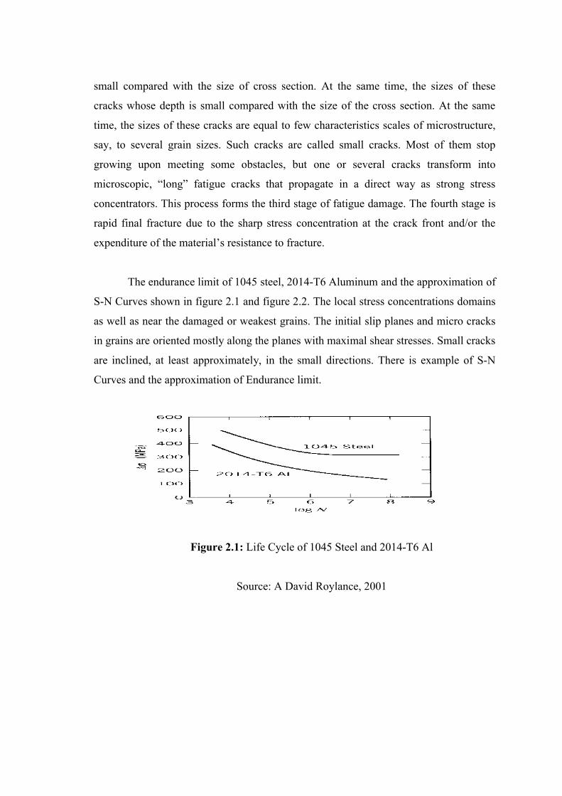
The endurance limit of 1045 steel, 2014-T6 Aluminum and the approximation of
S-N Curves shown in figure 2.1 and figure 2.2. The local stress concentrations domains
as well as near the damaged or weakest grains. The initial slip planes and micro cracks
in grains are oriented mostly along the planes with maximal shear stresses. Small cracks
are inclined, at least approximately, in the small directions. There is example of S-N
Curves and the approximation of Endurance limit.
Figure 2.1: Life Cycle of 1045 Steel and 2014-T6 Al
Source: A David Roylance, 2001
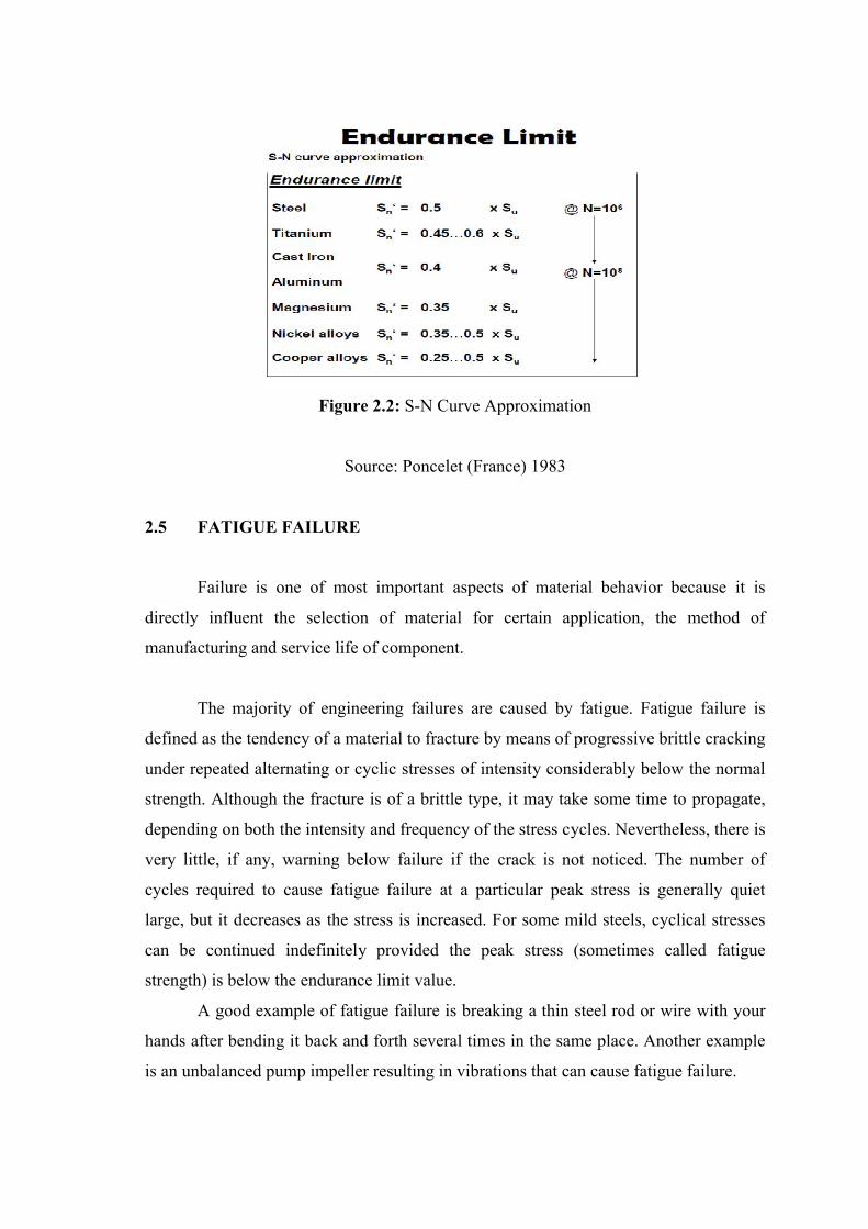
Figure 2.2: S-N Curve Approximation
Source: Poncelet (France) 1983
2.5 FATIGUE FAILURE
Failure is one of most important aspects of material behavior because it is
directly influent the selection of material for certain application, the method of
manufacturing and service life of component.
The majority of engineering failures are caused by fatigue. Fatigue failure is
defined as the tendency of a material to fracture by means of progressive brittle cracking
under repeated alternating or cyclic stresses of intensity considerably below the normal
strength. Although the fracture is of a brittle type, it may take some time to propagate,
depending on both the intensity and frequency of the stress cycles. Nevertheless, there is
very little, if any, warning below failure if the crack is not noticed. The number of
cycles required to cause fatigue failure at a particular peak stress is generally quiet
large, but it decreases as the stress is increased. For some mild steels, cyclical stresses
can be continued indefinitely provided the peak stress (sometimes called fatigue
strength) is below the endurance limit value.
A good example of fatigue failure is breaking a thin steel rod or wire with your
hands after bending it back and forth several times in the same place. Another example
is an unbalanced pump impeller resulting in vibrations that can cause fatigue failure.
The type of fatigue of most concern in circuit cards, gasoline, diesel, gas turbine
engines and many industrial applications is thermal fatigue. Thermal fatigue can arise
from thermal stresses produced by cyclic changes in temperature.
Fundamental requirements during design and manufacturing for avoiding fatigue
failure are different for different cases and should be considered during design phase.
Fatigue failures almost always begin at the surface of a material. The reasons are:
1. The most highly-stresses fibers are located at the surface (bending fatigue)
2. The intergranular flaws which precipitate tension failure are most frequently
found at the surface.
Suppose that a particular specimen is being fatigue tested. Now suppose the
fatigue test is halted after 20% to 25% of the expected life of the specimen, and the
surface condition is restored to its original state. Now the fatigue test is resumed at the
same stress level as before. The life of the part will be considerably longer than
expected. If that process is repeated several times, the life of the part may be extended
by several hundred percent, limited only by the available cross section of the specimen.
That proves fatigue failures originate at the surface of a component.
Fatigue failure is also due to crack formation and propagation. A fatigue crack
will typically initiate at a discontinuity in the material where the cyclic stress is a
maximum. Discontinuities can arise because of:
1. Design of rapid changes in cross-section, keyways, holes, etc. where the
cyclic stress concentrations occur.
2. Element that roll and/or slide each other (bearings, gears, cams ) under high
contact pressure, developing concentrated subsurface contact surfaces that
can cause pitting from after many cycles of the load.
3. Carelessness in locations of stamp marks, tool marks, scratches, and burrs;
poor joint design; improper assembly; and other fabrications faults.
4. Compositions of the material itself as processed by rolling, forging, casting,
extrusion, drawing and heat treatment. Microscopic and submicroscopic

surface and subsurface discontinuities arise. ( Joseph E Shigley, Charles R.
Mischke, Richard G. Budynas, 2004 )
Fatigue fracture typically occurs in material of basically brittle nature. External
or internal cracks develop at pre-existing flaws or fault of defects in the material; these
cracks then propagate and eventually they lead to total failure of part. The fracture
surface in fatigue is generally characterized by the term “beach marks”. Examples of
fatigue failure can be shown as the following figures:
Figure 2.3: Fatigue failures on crankshaft
Source: Serope Kalpakjian, Steven R. Schmid. 2000
Figure 2.4: Fracture of a bolt
Source: Serope Kalpakjian, Steven R. Schmid. 2000