Embed Size (px)
Citation preview

Torsten Braun, Michel Diaz, Jose Enrıquez-Gabeiras, and Thomas Staub
End-to-End Quality of ServiceOver Heterogeneous Networks
February 12, 2008
Springer


Foreword
v


Preface
The Internet has evolved from an academic network for data applications such asfile transfer and net news, to a global general-purpose network used for a varietyof different applications covering electronic mail, voiceover IP, television, peer-to-peer file sharing, video streaming and many more. The heterogeneity of appli-cations results in rather different application requirements in terms of bandwidth,delay, loss, etc. Ideally, the underlying network supportssuch Quality-of-Serviceparameters such that applications can request the desired services from the network,and do not need to take actions by themselves to achieve the desired communica-tion quality. Initially, the Internet was not designed to support Quality-of-Service,and only since the last decade have appropriate mechanisms been developed. Thosemechanisms mainly operate on the Internet Protocol (IP) level, but also network-specific mechanisms—e.g., targeted to particular wired/wireless access networktechnologies—are required.
The goal of the European 6th Framework Programme (FP6) Integrated Project”End-to-end Quality of Service Support over HeterogeneousNetworks” (EuQoS)was to develop, implement, and evaluate concepts and mechanisms to support QoSend-to-end, meaning that QoS mechanisms in end systems, access networks, inter-domain links and within domains must be supported. The EuQoSproject developedan impressive set of innovative solutions and novel scientific ideas to support end-to-end QoS in the Internet. New mechanisms and concepts were designed and imple-mented in a European-wide distributed testbed. In additionto the rather technicaldesign and implementation work, the project also developedtraining material in-troducing basic QoS mechanisms and techniques. Several e-learning modules weredeveloped and are currently being used at several partner universities for teachingon MSc or PhD levels.
The significant technical and educational results achievedduring the EuQoSproject, motivated us to use the gained knowledge and experiences of the projectpartners and write this book on end-to-end QoS in heterogeneous IP networks. Thebook basically consists of three parts. In Chapters 1-4, we discuss QoS mecha-nisms and protocols such as scheduling schemes, QoS architectures metrics andmeasurement techniques, traffic engineering and signalling protocols, and the latest
vii

viii Preface
standardisation activities. Chapter 5 describes related work and recent developmentin the area of transport protocols, in particular how TCP canbe optimised towardsQoS support and fairness. The EuQoS system presented in Chapter 6 extends andcombines the basic mechanisms discussed in the previous chapters. We show how acombination of different QoS enabling mechanisms and protocols can be used andextended to build a comprehensive end-to-end QoS architecture over heterogeneouswired/wireless access networks. To evaluate QoS mechanisms and architectures, ap-propriate evaluation schemes are required. The two chapters in the annex describehow simulation—in particular the well-known network simulator ns-2—as well asemulation techniques can be used for tests and evaluations.
This book, which is based on the achievements of the EuQoS project, would nothave been possible to compile without the funding from the European Commission,as well as the tremendous efforts and enthusiasm of all the people involved in theproject. Special thanks to Mark Gunter for proof-reading the text contributions tothis book.
Torsten BraunMichel Diaz
Jose Enriquez GabeirasBern, Toulouse, Madrid. January 2008. Thomas Staub
Acknowledgements
The book editors and authors would like to thank all people who were involved inthe EuQoS project:
• Telefonica I+D: Jose Enrıquez Gabeiras, Francisco Javier Ramon Salguero, Ger-ardo Garcıa de Blas, Antonio J. Elizondo Armengol, Francisco, Romero Bueno,Jesus Bravo lvarez, Jorge Andres Colas, MarıaAngeles, Callejo Rodrıguez,Marıa Luisa Garcıa Osma
• University of Pisa (CPR/UoPisa):Enzo Mingozzi, Giovanni Stea, LucianoLenzini, Luca Bisti, Claudio Cicconetti, Linda Martorini,Abraham Gebrehiwot,Simone Bisogni, Paolo Sozzi
• Elsag Datamat:Enrico Angori, Giuseppe Martufi, Marco Carusio, AlessandroGiorgini, Andrea Paselli, Giovanni Saccomandi, Marco Mauro
• CNRS (LAAS-CNRS, ENSICA): Michel Diaz, Florin Racaru, Ernesto Expos-ito, Philippe Owezarski, Patrick Senac , Christophe Chassot , Nicolas Larrieu,Laurent Dairaine, Mathieu Gineste, Nicolas Van Wambeke, Slim Abdellatif,Sebastien Ardon, Roberto Willrich, Guillaume Auriol, Silvia Farraposo
• France Telecom R&D:Olivier Dugeon, Walid Htira, Michel Bourbao, Pascal LeGuern, Jean-Louis Le Roux, Stephane Statiotis, Regis Fr´echin, Claire Teisseire
• Polska Telefonia Cyfrowa (ERA):Michal Obuchowicz, Robert Parzydo , AdamFlizikowski, Edyta Rafalska, Karol Jez, Krzysztof Horszczaruk, Krzysztof Bro-narski, Krzysztof Samp, Maciej Rozowicz, Michal Dudzinski, Pawel Caban, Pi-otr Zadroga, Slawomir Tkacz
• Martel: Martin Potts, Mark Guenter, Sandra Wittwer• NICTA: Emmanuel Lochin, Guillaume Jourjon, Sebastien Ardon, Ernesto Ex-
posito, Feiselia Tan, Laurent Dairaine• PointerCom: Roberto Marega, Stefano Salsano, Donald Papalilo, Gianluca Mar-
tiniello, Valeria Calcagni• Polish Telecom R&D: Zbigniew Kopertowski, Jaroslaw Kowalczyk, Tomasz
Ciszkowski
ix

x Acknowledgements
• Portugal Telecom Inovacao (PTIN): Jorge Carapinha, Nuno Carapeto, PauloLoureiro, Arnaldo Santos, Eduardo Silva, Fernando Santiago, Helena PaulaMatos, Hugo Manaia, Isabel Borges, Jacinto Barbeira, Filipe Peixinho.
• Red Zinc: Donal Morris, Brian Widger, Diarmuid O Neill, Lea Compin, OscarCuidad
• Silogic: Laurent Baresse, Benoıt Baurens, Jean-Philippe Darmet, Yannick Lizzi,Francois Meaude
• INDRA ( previously SOLUZIONA): Ignacio Fresno, Jaime Orozco, Luis Col-lantes Abril, Pablo Vaquero Barbon, Ruben Romero San Martın, Jorge Alonso,Maria Lurdes Sousa, Raul Manzano Barroso
• Telscom AG:Sathya Rao, Marcin Michalak• Technical University of Catalonia (UPC): Jordi Domingo-Pascual, Lorand
Jakab, Marcelo Yannuzzi, Rene Serral-Gracia, Xavier Masip-Bruin• University of Bern: Torsten Braun, Thomas Staub, Dragan Milic, Marc Brogle,
Marc-Alain Steinemann, Thomas Bernoulli, Gerald Wagenknecht, Markus Wulff,Patrick Lauer, Markus Anwander, Matthias Scheidegger
• University of Paderborn/C-LAB: Isabell Jahnich, Achim Rettberg, Chris Loeser,Michael Ditze, Kay Klobedanz, Sebastian Seitz, Andreas Konig, Volker Spaar-mann, Matthias Grawinkel
• University of Rome: Antonio Pietrabissa, Francesco Delli Priscoli, Sabrina Gi-ampaoletti, Emiliano Guainella, Erasmo Di Santo, Gianfranco Santoro, IlariaMarchetti, Massimiliano Rossi
• Universidade de Coimbra: Edmundo Monteiro, Luıs Cordeiro, Bruno Car-valho, Fernando Boavida, Gabriela Batista Leao, Isidro Caramelo, Jian Zhang,Jorge Sa Silva, Marilia Curado, Maxwel Carmo, Paulo Simoes, Romulo Ribeiro,Vitor Bernardo, David Palma, Rui Vilao, Luıs Conceicao
• Warsaw University of Technology: Wojciech Burakowski, Andrzej Beben,Halina Tarasiuk, Jaroslaw Sliwinski, Jordi Mongay Batalla, Marek Dabrowski,Piotr Krawiec, Robert Janowski
• Ericsson: Antoine de Poorter, Julio Lopez Roldan, Miguel Angel Recio, JesusRenero Quintero, Jose Luis Agundez
• Hospital Divino Espirito Santo: Jose Manuel Ponte, Antonio Vasco Viveiros,Carlos P. Duarte, Paula Maciel, Jose M. Jesus Silva, Maura Medeiros, MariaDulce Raposo

Contents
1 Motivation and Basics . . . . . . . . . . . . . . . . . . . . . . . . . . . . . . . . . . . . . . . . . . 11.1 Quality of Service and its Parameters . . . . . . . . . . . . . . . .. . . . . . . . . . 1
1.1.1 Delay and Delay Variations in End-to-End Packet Delivery . 21.1.2 Bandwidth and Packet Loss Ratio . . . . . . . . . . . . . . . . . . .. . . 4
1.2 Applications’ QoS Requirements . . . . . . . . . . . . . . . . . . . .. . . . . . . . . 51.2.1 Types of Network Applications . . . . . . . . . . . . . . . . . . . .. . . . 51.2.2 QoS Requirements of Applications . . . . . . . . . . . . . . . . .. . . . 7
1.3 Packet Scheduling in Network Elements . . . . . . . . . . . . . . .. . . . . . . . 91.3.1 (Non)Work-conserving Scheduling Disciplines . . . . .. . . . . . 91.3.2 Fairness . . . . . . . . . . . . . . . . . . . . . . . . . . . . . . . . . . . . . .. . . . . . 101.3.3 Scheduling Disciplines . . . . . . . . . . . . . . . . . . . . . . . . .. . . . . . 111.3.4 Packet Dropping . . . . . . . . . . . . . . . . . . . . . . . . . . . . . . . .. . . . 12
1.4 Quality-of-Service Architectures . . . . . . . . . . . . . . . . .. . . . . . . . . . . . . 131.4.1 Integrated Services . . . . . . . . . . . . . . . . . . . . . . . . . . . .. . . . . . 131.4.2 Differentiated Services. . . . . . . . . . . . . . . . . . . . . . . .. . . . . . . . 151.4.3 End-To-End QoS Mechanisms . . . . . . . . . . . . . . . . . . . . . . .. . 17
1.5 Implementation and Performance of QoS-aware Applications. . . . . . 191.5.1 Prequisites for Successful QoS Applications . . . . . . .. . . . . . . 191.5.2 Media Scaling . . . . . . . . . . . . . . . . . . . . . . . . . . . . . . . . . .. . . . . 191.5.3 Applications’ Performance Gain Due to QoS . . . . . . . . . .. . . 201.5.4 Summary . . . . . . . . . . . . . . . . . . . . . . . . . . . . . . . . . . . . . . .. . . . 22
1.6 Structure of the Book . . . . . . . . . . . . . . . . . . . . . . . . . . . . . .. . . . . . . . . 22
2 QoS Measurements in IP-based Networks. . . . . . . . . . . . . . . . . . . . . . . . . 252.1 Introduction . . . . . . . . . . . . . . . . . . . . . . . . . . . . . . . . . . . .. . . . . . . . . . . 252.2 Measurement Metrics . . . . . . . . . . . . . . . . . . . . . . . . . . . . . .. . . . . . . . . 26
2.2.1 Network Level . . . . . . . . . . . . . . . . . . . . . . . . . . . . . . . . . .. . . . 262.2.2 Call level . . . . . . . . . . . . . . . . . . . . . . . . . . . . . . . . . . . . .. . . . . . 302.2.3 User Level . . . . . . . . . . . . . . . . . . . . . . . . . . . . . . . . . . . . .. . . . . 32
2.3 Measurement Techniques . . . . . . . . . . . . . . . . . . . . . . . . . . .. . . . . . . . . 362.3.1 Previous Considerations . . . . . . . . . . . . . . . . . . . . . . . .. . . . . . 36
xi

xii Contents
2.3.2 Base Techniques . . . . . . . . . . . . . . . . . . . . . . . . . . . . . . . .. . . . . 392.3.3 Active Measurements . . . . . . . . . . . . . . . . . . . . . . . . . . . .. . . . . 412.3.4 Passive Measurements . . . . . . . . . . . . . . . . . . . . . . . . . . .. . . . . 47
2.4 Conclusions . . . . . . . . . . . . . . . . . . . . . . . . . . . . . . . . . . . . .. . . . . . . . . . 51
3 Traffic Engineering . . . . . . . . . . . . . . . . . . . . . . . . . . . . . . . . . . . . . . . . . . . . . 533.1 Introduction . . . . . . . . . . . . . . . . . . . . . . . . . . . . . . . . . . . .. . . . . . . . . . . 533.2 A Motivating Example . . . . . . . . . . . . . . . . . . . . . . . . . . . . . .. . . . . . . . 543.3 Multi-Protocol Label Switching Architecture . . . . . . . .. . . . . . . . . . . 56
3.3.1 The Forwarding Component . . . . . . . . . . . . . . . . . . . . . . . .. . . 573.3.2 The Control Component . . . . . . . . . . . . . . . . . . . . . . . . . . .. . . 593.3.3 MPLS Optimisation . . . . . . . . . . . . . . . . . . . . . . . . . . . . . .. . . . 60
3.4 MPLS-based Traffic Engineering . . . . . . . . . . . . . . . . . . . . .. . . . . . . . 623.4.1 Constraint-Based Routing . . . . . . . . . . . . . . . . . . . . . . .. . . . . 623.4.2 Explicit Route Signalling . . . . . . . . . . . . . . . . . . . . . . .. . . . . . 663.4.3 Traffic Engineering Practices . . . . . . . . . . . . . . . . . . . .. . . . . . 69
3.5 Traffic Engineering and Quality of Service . . . . . . . . . . . .. . . . . . . . . 713.5.1 QoS Support over MPLS . . . . . . . . . . . . . . . . . . . . . . . . . . . .. . 723.5.2 Traffic Engineering Extensions for DiffServ . . . . . . . .. . . . . . 74
3.6 Conclusions . . . . . . . . . . . . . . . . . . . . . . . . . . . . . . . . . . . . .. . . . . . . . . . 78
4 Signalling . . . . . . . . . . . . . . . . . . . . . . . . . . . . . . . . . . . . . . . . . . . . . . . . . . .. . 794.1 Introduction . . . . . . . . . . . . . . . . . . . . . . . . . . . . . . . . . . . .. . . . . . . . . . . 794.2 Session Initiation Protocol (SIP) . . . . . . . . . . . . . . . . . .. . . . . . . . . . . . 80
4.2.1 SIP and Its Value Propositions . . . . . . . . . . . . . . . . . . . .. . . . . 804.2.2 Protocol Components . . . . . . . . . . . . . . . . . . . . . . . . . . . .. . . . . 814.2.3 SIP Messages . . . . . . . . . . . . . . . . . . . . . . . . . . . . . . . . . . .. . . . 844.2.4 Session Description . . . . . . . . . . . . . . . . . . . . . . . . . . . .. . . . . . 874.2.5 Establishment of a SIP Session . . . . . . . . . . . . . . . . . . . .. . . . . 884.2.6 SIP’s Extension . . . . . . . . . . . . . . . . . . . . . . . . . . . . . . . .. . . . . . 91
4.3 The Next Steps In Signalling (NSIS) . . . . . . . . . . . . . . . . . .. . . . . . . . 914.3.1 Background and main Characteristics . . . . . . . . . . . . . .. . . . . 914.3.2 Background and Main Characteristics . . . . . . . . . . . . . .. . . . . 924.3.3 Overview of Signalling Scenarios and Protocol Structure . . . 954.3.4 The NSIS Layer Transport Protocol . . . . . . . . . . . . . . . . .. . . . 96
4.4 Common Open Policy Service (COPS) . . . . . . . . . . . . . . . . . . .. . . . . 1044.4.1 COPS Overview . . . . . . . . . . . . . . . . . . . . . . . . . . . . . . . . . .. . . 1044.4.2 Basic Model . . . . . . . . . . . . . . . . . . . . . . . . . . . . . . . . . . . .. . . . 1054.4.3 COPS Protocol . . . . . . . . . . . . . . . . . . . . . . . . . . . . . . . . . .. . . . 1064.4.4 COPS Messages . . . . . . . . . . . . . . . . . . . . . . . . . . . . . . . . . .. . . 1104.4.5 Common Operation . . . . . . . . . . . . . . . . . . . . . . . . . . . . . . .. . . 1134.4.6 Illustrative Examples, Using COPS for RSVP . . . . . . . . .. . . 114
4.5 Conclusions . . . . . . . . . . . . . . . . . . . . . . . . . . . . . . . . . . . . .. . . . . . . . . . 116

Contents xiii
5 Enhanced Transport Protocols. . . . . . . . . . . . . . . . . . . . . . . . . . . . . . . . . . . 1175.1 Introduction . . . . . . . . . . . . . . . . . . . . . . . . . . . . . . . . . . . .. . . . . . . . . . . 1175.2 State of the Art of Transport Protocols . . . . . . . . . . . . . . .. . . . . . . . . . 118
5.2.1 TCP and UDP . . . . . . . . . . . . . . . . . . . . . . . . . . . . . . . . . . . . .. . 1195.2.2 TCP Evolution . . . . . . . . . . . . . . . . . . . . . . . . . . . . . . . . . .. . . . 1205.2.3 SCTP . . . . . . . . . . . . . . . . . . . . . . . . . . . . . . . . . . . . . . . . . .. . . . 1225.2.4 DCCP. . . . . . . . . . . . . . . . . . . . . . . . . . . . . . . . . . . . . . . . . .. . . . 1235.2.5 Discussion . . . . . . . . . . . . . . . . . . . . . . . . . . . . . . . . . . . .. . . . . . 124
5.3 Transport Mechanisms . . . . . . . . . . . . . . . . . . . . . . . . . . . . .. . . . . . . . . 1245.3.1 Overview . . . . . . . . . . . . . . . . . . . . . . . . . . . . . . . . . . . . . .. . . . . 1245.3.2 Congestion Control Mechanisms . . . . . . . . . . . . . . . . . . .. . . . 1265.3.3 Reliability Mechanisms . . . . . . . . . . . . . . . . . . . . . . . . .. . . . . . 1275.3.4 Discussion . . . . . . . . . . . . . . . . . . . . . . . . . . . . . . . . . . . .. . . . . . 128
5.4 Enhanced Transport Protocol Mechanisms. . . . . . . . . . . . .. . . . . . . . . 1295.4.1 TFRC and gTFRC, a QoS-aware Congestion Control . . . . . .1295.4.2 Application-Aware Transport Mechanisms . . . . . . . . . .. . . . . 130
5.5 Conclusion . . . . . . . . . . . . . . . . . . . . . . . . . . . . . . . . . . . . . .. . . . . . . . . . 136
6 The EuQoS System. . . . . . . . . . . . . . . . . . . . . . . . . . . . . . . . . . . . . . . . . . . . . 1376.1 Introduction . . . . . . . . . . . . . . . . . . . . . . . . . . . . . . . . . . . .. . . . . . . . . . . 1386.2 Architecture . . . . . . . . . . . . . . . . . . . . . . . . . . . . . . . . . . . .. . . . . . . . . . . 139
6.2.1 Goals and Requirements . . . . . . . . . . . . . . . . . . . . . . . . . .. . . . 1396.2.2 Functional Blocks and their Main Functions . . . . . . . . .. . . . . 1406.2.3 Control Plane Elements: RM and RA . . . . . . . . . . . . . . . . . .. 143
6.3 Provisioning, Invocation, and Operation, Administration andManagement . . . . . . . . . . . . . . . . . . . . . . . . . . . . . . . . . . . . . . . . .. . . . . 1456.3.1 Provisioning Process . . . . . . . . . . . . . . . . . . . . . . . . . . .. . . . . . 1466.3.2 Invocation Process . . . . . . . . . . . . . . . . . . . . . . . . . . . . .. . . . . . 1526.3.3 Operation, Administration and Management . . . . . . . . .. . . . . 156
6.4 End-to-End Classes of Service in Heterogeneous Networks . . . . . . . 1566.4.1 End-to-end Classes of Service in EuQoS . . . . . . . . . . . . .. . . . 1576.4.2 QoS Mechanisms and Algorithms for Specification of e2e
Classes of Service . . . . . . . . . . . . . . . . . . . . . . . . . . . . . . . . . . .. 1606.4.3 Implementation of e2e Classes of Service in Underlying
Technologies . . . . . . . . . . . . . . . . . . . . . . . . . . . . . . . . . . . . . . .. 1626.5 EuQoS Enhanced Transport Protocol . . . . . . . . . . . . . . . . . .. . . . . . . . 168
6.5.1 Introduction . . . . . . . . . . . . . . . . . . . . . . . . . . . . . . . . . .. . . . . . . 1686.5.2 Enhanced Transport Protocol Services for EuQoS . . . . .. . . . 1696.5.3 Services for Streaming/Non-Streaming Applications. . . . . . 170
6.6 Multicast . . . . . . . . . . . . . . . . . . . . . . . . . . . . . . . . . . . . . . .. . . . . . . . . . 1716.6.1 Application Layer Multicast . . . . . . . . . . . . . . . . . . . . .. . . . . . 1726.6.2 Application Layer Multicast in the EuQoS System . . . . .. . . 1736.6.3 Multicast Middleware . . . . . . . . . . . . . . . . . . . . . . . . . . .. . . . . 1756.6.4 Introducing QoS to Multicast Middleware . . . . . . . . . . .. . . . 178
6.7 Telemedicine Application . . . . . . . . . . . . . . . . . . . . . . . . .. . . . . . . . . . . 180

xiv Contents
6.7.1 Telemedicine – the Case for Application-Driven QoS . .. . . 1806.7.2 Overview of Medigraf . . . . . . . . . . . . . . . . . . . . . . . . . . . .. . . . 1806.7.3 Medigraf Adaptation to EuQoS . . . . . . . . . . . . . . . . . . . . .. . . 182
6.8 Conclusions . . . . . . . . . . . . . . . . . . . . . . . . . . . . . . . . . . . . .. . . . . . . . . . 184
7 Summary and Outlook . . . . . . . . . . . . . . . . . . . . . . . . . . . . . . . . . . . . . . . . . 187
A Implementing Protocols on Network Simulators . . . . . . . . . . . . . . . . . . . 189A.1 Main Simulation Terms and Concepts . . . . . . . . . . . . . . . . . .. . . . . . . 189
A.1.1 Simulation Process . . . . . . . . . . . . . . . . . . . . . . . . . . . . .. . . . . . 190A.1.2 Simulation Types . . . . . . . . . . . . . . . . . . . . . . . . . . . . . . .. . . . . 190
A.2 Network Simulation . . . . . . . . . . . . . . . . . . . . . . . . . . . . . . .. . . . . . . . . 191A.2.1 Parallel/Distributed versus Serial Execution of Simulations . 192A.2.2 Packet-Level, Fluid-Based and Hybrid Model Simulation . . . 192A.2.3 Simulation Speedup . . . . . . . . . . . . . . . . . . . . . . . . . . . . .. . . . . 193A.2.4 Network Simulation in Research . . . . . . . . . . . . . . . . . . .. . . . 193A.2.5 Simulation for Education Purposes . . . . . . . . . . . . . . . .. . . . . 195
A.3 Network Simulators . . . . . . . . . . . . . . . . . . . . . . . . . . . . . . .. . . . . . . . . 195A.3.1 GloMoSim and Qualnet . . . . . . . . . . . . . . . . . . . . . . . . . . . .. . . 195A.3.2 JiST/SWANS . . . . . . . . . . . . . . . . . . . . . . . . . . . . . . . . . . . .. . . 196A.3.3 Scalable Simulation Framework (SSF) and SSFNet . . . . .. . . 196A.3.4 OMNeT++ and OMNEST . . . . . . . . . . . . . . . . . . . . . . . . . . . . . 196
A.4 The Network Simulator ns-2 . . . . . . . . . . . . . . . . . . . . . . . . .. . . . . . . . 197A.4.1 The Language Concept . . . . . . . . . . . . . . . . . . . . . . . . . . . .. . . 197A.4.2 Hierarchical Structure . . . . . . . . . . . . . . . . . . . . . . . . .. . . . . . . 198A.4.3 First Steps - Simulation Script Template . . . . . . . . . . .. . . . . . 199A.4.4 Nodes, Links and Traffic . . . . . . . . . . . . . . . . . . . . . . . . . .. . . . 199A.4.5 Wireless Networks . . . . . . . . . . . . . . . . . . . . . . . . . . . . . .. . . . . 202A.4.6 Implementing Protocols with ns-2 . . . . . . . . . . . . . . . . .. . . . . 204A.4.7 Tips for Running ns-2 Simulations . . . . . . . . . . . . . . . . .. . . . . 219A.4.8 Analysing Methods . . . . . . . . . . . . . . . . . . . . . . . . . . . . . .. . . . 220
B Network Emulation Focusing on QoS-Oriented SatelliteCommunication . . . . . . . . . . . . . . . . . . . . . . . . . . . . . . . . . . . . . . . . . . . . . . . . 221B.1 Network Emulation Basics . . . . . . . . . . . . . . . . . . . . . . . . . .. . . . . . . . . 221
B.1.1 Introduction to Network Emulation . . . . . . . . . . . . . . . .. . . . . 221B.1.2 What is Network Emulation? . . . . . . . . . . . . . . . . . . . . . . .. . . 223B.1.3 Why Using Network Emulation? . . . . . . . . . . . . . . . . . . . . .. . 226B.1.4 Requirements for Emulation Systems . . . . . . . . . . . . . . .. . . . 228B.1.5 Network Emulation System Approaches . . . . . . . . . . . . . .. . 230
B.2 Case Study: Emulation of QoS-oriented Satellite Communication . . 241B.2.1 Introduction . . . . . . . . . . . . . . . . . . . . . . . . . . . . . . . . . .. . . . . . . 241B.2.2 DVB Satellite Communications . . . . . . . . . . . . . . . . . . . .. . . . 241B.2.3 QoS Support for Satellite Network Systems . . . . . . . . . .. . . . 243B.2.4 Emulation of a DVB-S, DVB-RCS Satellite System . . . . . .. 244

Contents xv
B.3 Conclusions . . . . . . . . . . . . . . . . . . . . . . . . . . . . . . . . . . . . .. . . . . . . . . . 253References . . . . . . . . . . . . . . . . . . . . . . . . . . . . . . . . . . . . . . . . .. . . . . . . . . . . . 255
Index . . . . . . . . . . . . . . . . . . . . . . . . . . . . . . . . . . . . . . . . . . . . . . . . . . .. . . . . . . . . . 265


Acronyms
The following list contains acronyms used in the book and their explanation. Mostacronyms can be found in the index as well together with a pagereference.
ALM Application layer multicastAPI Application programming interfaceCIDR Classless Internet domain routingCOPS Common Open Policy ServiceDVMRP Distance-vector multicast routing protocolIGMP Internet group management protocolIP Internet protocolIPTV Internet Protocol TelevisionIPv4 Internet protocol version 4IPv6 Internet protocol version 6ISP Internet service providerMM Multicast MiddlewareMOSPF Multicast open shortest path firstNSIS Next Step In SignallingP2P Peer-to-peerPDP Policy Decision PointPEP Policy Enforcement PointPIM Protocol-independant multicastQoS Quality of ServiceSDP Session Description ProtocolSE Signalling EntitiesSIP Session initiation ProtocolSSQ Synchronize State QueryTCP Transmission control protocolTTL Time-To-LiveUAC User Agent ClientUAS User Agent ServerUDP User datagram protocol
xvii
xviii Acronyms
VLSM Variable length subnet maskMPLS Multi Protocol Label SwitchingTE Traffic EngineeringRIP Routing Information ProtocolIGP Interior Gateway ProtocolOSPF Open Shortest Path FirstIS-IS Intermediate System-Intermediate SystemRSVP ReSerVation ProtocolIETF Internet Engineering Task ForceFEC Forwarding Equivalence ClassLSR Label-Switching RouterLFIB Label Forwarding Information BaseATM Asynchronous Transfer ModeDLCI Data-Link Connection IdentifierVPI Virtual Path IdentifierVCI Virtual Channel IdentifierBGP Border Gateway ProtocolLDP Label Distribution ProtocolLIB Label Information BaseLSP Label-Switched PathCBR Constraint-Based RoutingTED Traffic Engineering DatabaseCSPF Constrained Shortest Path FirstSPF Shortest Path FirstCR-LDP Constraint-based Routing Label Distribution ProtocolTSPEC Traffic SpecificationERO Explicit Route ObjectBA Behavior AggregatePHB Per Hop BehaviorDSCP Diff-Serv CodepointOA Ordered AggregatePSC PHB Scheduling ClassAF Assured ForwardingE-LSP EXP-Inferred-PSC LSPL-LSP Label-Only-Inferred-PSC LSPBE Best EffortDS-TE Diff-Serv-aware Traffic EngineeringCT Class TypeBC Bandwidth ConstraintMAM Maximum Allocation Bandwidth Constraints ModelRDM Russian Doll Bandwidth Constraints ModelAC Access CategoryADSL Asymmetric DSLAIFS Arbitrary Inter-Frame SpaceAP Access Point

Acronyms xix
AS Autonomous SystemsASPB AS-path BuilderATM Asynchronous Transfer ModeBR Border RouterBRAS Broadband Remote Access ServerBRPC Backward Recursive Path ComputationCAC Connection Admission ControlCBR Constant Bit RateCoS Class of ServiceCPE Customer Premises EquipmentCRA Continuous Rate AssignmentCW Contention WindowDAMA Demand Assignment Multiple AccessDCF Distributed Coordination FunctionDSL Digital Subscriber LineDSLAM Digital Subscriber Line Access MultiplexerDVB-S Digital Video Broadcasting - SatelliteDVB-RCS Digital Video Broadcasting - Reverse Channel Satellitee2e CoS End-to-end Class of ServiceEDCA Enhanced Distributed Coordination AccessER Edge RouterES Ethernet SwitchFCA Free Capacity AssignmentFTP File Transfer ProtocolGGSN GPRS Gateway Support NodeHTD High Throughput DataIPLR IP Packet Loss RatioIPTD IP Packet Transfer DelayIPDV IP Packet Delay VariationMAC Medium Access ControlMT Mobile TerminalNCC Network Control CentreNRT Non Real TimeOGGSN Open GPRS Gateway Support NodePCC Path Computation ClientPCE Path Computation ElementPCEP PCE ProtocolPQ Priority QueuingPR Peak RateRA Resource AllocatorRBDC Rate Based Dynamic CapacityRM Resource ManagerRNC Radio Network ControllerRT Real TimeSHDSL Symmetrical High Bitrate DSL

xx Acronyms
SLA Service Level AgreementST Satellite TerminalSTD StandardTERO Traffic Engineering and Resource OptimizationTOS (Type of Service)UTRAN UMTS Terrestrial Radio Access NetworkVBDC Volume Based Dynamic CapacityVBR Variable Bit RateVDSL Very High Bitrate DSLVoD Video on DemandVoIP Voice over IPVTC Video TeleconferenceWFQ Weighted Fair QueueingWMM WiFi Multi-MediaWRED Weighted Random Early DetectionWRR Weighted Round-RobinCLI Command Line InterfaceEQ-BGP Enhanced QoS Border Gateway ProtocolQoS NLRI QoS Network Layer Reachability InformationDoP Degree of PreferenceSNMP Simple Network Management ProtocolTMN Telecommunications Management NetworkSAAA Security, Authentication, Authorization and AccountingQoSR Quality of Service RoutingxDSL Digital Subscriber LineUMTS Universal Mobile Telecommunications SystemLAN Local Area NetworkNREN National REsearch NetworkGEANT Multi-gigabit pan-European data communications networkNTI Network Technology IndependentNTD Network Technology DependentAQ-SSN Application Quality Signalling and Service NegotiationCHAR CHARging moduleQCM Quality Control ModuleMMS Monitoring and Measurement SystemEQ-SAP EQ-Service Access PointPQ-WFQ Priority Queueing - Weighted Fair QueueingSCTP Stream Control Transmission ProtocolDCCP Datagram Congestion Control ProtocolETP Enhanced Transport ProtocolgTFRC TCP-Friendly Rate Congestion ControlTC Time ConstraintsSACK Selective ACKnowledgementPCMA Pulse Code Modulation a-lawPCMU Pulse Code Modulation mu-law

Acronyms xxi
CIF Common Intermediate FormatQCIF Quarter Common Intermediate FormatSQCIF Sub Quarter Common Intermediate Formate2e end-to-end


Chapter 6The EuQoS System
Michel Diaz, Jose Enrıquez-Gabeiras, Laurent Baresse, Andrzej Beben,Wojciech Burakowski, Marıa Angeles Callejo-Rodrıguez, Jorge Carapinha,Olivier Dugeon, Ernesto Exposito, Mathieu Gineste, Enzo Mingozzi, Edmundo Monteiro, Antonio Pietrabissa, Florin Racaru, JarosławSliwinski,Giovanni Stea, Halina Tarasiuk, Nicolas Van Wambeke, and Markus Wulff
Abstract The project “End-to-End Quality of Service support over heterogeneousnetworks” (EuQoS) is an European research project which has defined a novel ar-chitecture that builds, uses and manages the end-to-end (e2e) application exchangesand network paths with Quality of Service (QoS) guarantees across different admin-istrative domains and heterogeneous networks. This chapter presents the architec-ture of the EuQoS system as a case study of the concepts introduced in previouschapters. The EuQoS architecture provides a clear interface that allows the end userto request a specific QoS level, without changing its application signalling protocoland using the basic connectivity of the local service provider. A complete set of sup-porting functions has been implemented: i) Security, Authentication, Authorisationand Accounting (SAAA); ii) Admission Control; iii) Charging; iv) Signalling andService Negotiation; v) Monitoring and Measurements Functions and System (MM-F/MMS); vi) QoS Routing (QoSR); vii) Failure Management; viii) Traffic Engineer-ing and Resource Optimisation (TERO). The EuQoS system has been deployed asa prototype including all the above features, encompassing the most common ac-cess networks, i.e., xDSL, UMTS, WiFi, and Ethernet, connected through a corenetwork composed by the National Research and Education Networks (NRENs)of the project partners and GEANT (the European research network). This sectiondescribes the main features of the EuQoS system and presents the mechanisms, al-gorithms and protocols that have been developed in the project. The results achievedvalidate the design choices of the EuQoS system, and confirm the potential impactthat this project is likely to have in the near future.1
1 This work was partially funded by the European Commission through the EuQoS IntegratedProject (contract FP6-004503)
137

138 6 The EuQoS System
6.1 Introduction
Due to the increasing demand for using new multimedia applications over the Inter-net (such as VoIP, video streaming or telemedicine), the provision of QoS to thesenovel services is becoming a key driver for ISPs in the futureInternet. In this con-text, the main challenge is to guarantee the users QoS requirements between theend points involved in the communication; a new architecture is needed in orderto address this goal. Its main feature is the integration andsynchronisation of thetasks performed in the different planes of the networks along the end-to-end path.In order to address this issue, the EuQoS system has been designed to provide guar-anteed e2e QoS over different underlying network technologies. The EuQoS systembuilds, uses, and monitors e2e QoS paths across different administrative domains inheterogeneous networks.
This chapter presents the final architecture of the EuQoS system as a case studyof the concepts introduced in previous chapters, providinga view on how QoS de-livery can be supported in real environments using state of the art technologies. Thedifferent aspects of the architecture and the implementation of the EuQoS systemare introduced in the next sections:
• In Section 6.2a top level descriptionof the architecture and the main character-istics of the EuQoS system are introduced. This high level view presents the keyactions and protocols used to coordinate the different technologies and domainsin the e2e path. The behaviour of the network and the application levels, togetherwith the way the main system components work, are described.
• Section 6.3 containsthe functional descriptionof the system based on the threemain network design processes, i.e., Provisioning, Invocation and Operation, Ad-ministration and Management (OAM).
• Section 6.4 presentsthe framework for QoS provision, which specifies the EuQoSClasses of Service (CoS) and presents how they can be supported in differentunderlying network technologies.
• Section 6.5 shows, after the signalling and control phases,how the data will betransferred using an adequate transport layer. The six different transport layerservices now needed for handling the e2e application-to-application QoS for thedifferent underlying network CoSs are presented.
• Section 6.6 introduces the novel approach selected in the system to implementQoS multicast services. The EuQoS Multicast Middleware uses Scribe & Pastryfor defining the Peer-to-Peer (P2P) network and for buildingthe multicast trees.Pastry is a P2P routing substrate and Scribe builds an overlay structure on top ofPastry for multicast tree construction.
• Section 6.7 providesa real world exampleof how commercial applications canbe integrated into the EuQoS system. A telemedicine application (Medigraf) isintroduced, and the key aspects needed to integrate it in theEuQoS environmentare shown.
6.2 Architecture 139
USER 1
QCM
Application
Signalling
Application
Transport
ProtocolsAccess
Network
b
QoS
Domain
k
QoS
Domain
j
QoS
Domain
i
USER 1
QCM
Application
Signalling
Access
Network
a
RAa
Network Technology Independent layer
Network Technology Dependent layer
Application Signalling
RMa
Application
NSIS NSISNSIS NSIS
Proxy Proxy
AQ-SSN AQ-SSN
RAi RAj RAk RAb
RMb
Transport
Protocols
CO
PS
CO
PS
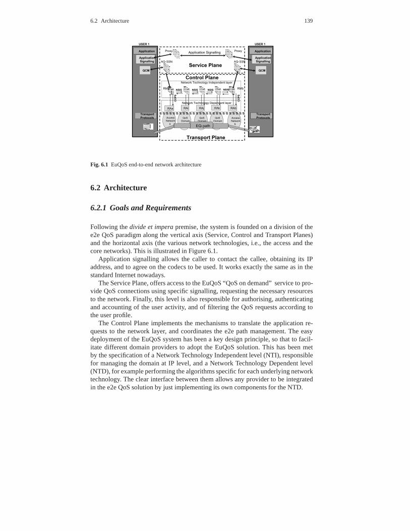
Fig. 6.1 EuQoS end-to-end network architecture
6.2 Architecture
6.2.1 Goals and Requirements
Following thedivide et imperapremise, the system is founded on a division of thee2e QoS paradigm along the vertical axis (Service, Control and Transport Planes)and the horizontal axis (the various network technologies,i.e., the access and thecore networks). This is illustrated in Figure 6.1.
Application signalling allows the caller to contact the callee, obtaining its IPaddress, and to agree on the codecs to be used. It works exactly the same as in thestandard Internet nowadays.
The Service Plane, offers access to the EuQoS “QoS on demand”service to pro-vide QoS connections using specific signalling, requestingthe necessary resourcesto the network. Finally, this level is also responsible for authorising, authenticatingand accounting of the user activity, and of filtering the QoS requests according tothe user profile.
The Control Plane implements the mechanisms to translate the application re-quests to the network layer, and coordinates the e2e path management. The easydeployment of the EuQoS system has been a key design principle, so that to facil-itate different domain providers to adopt the EuQoS solution. This has been metby the specification of a Network Technology Independent level (NTI), responsiblefor managing the domain at IP level, and a Network TechnologyDependent level(NTD), for example performing the algorithms specific for each underlying networktechnology. The clear interface between them allows any provider to be integratedin the e2e QoS solution by just implementing its own components for the NTD.

140 6 The EuQoS System
TransportPlane
EuQoS Client EuQoS Server
Control Plane
NTD level
NTI level
Application Service Plane
Measurements
COPS
Application
Network Devices (WiFi, LAN, UMTS, xDSL, Satellite, MPLS)
EQ- BGP
Transport
Protocols
SOAP
EQ-
BGP
AQ-SSN
NSIS
RM
RAMMS
Configuration ofnetwork devices
PCEPCEP
EQ-SAP
NSIS
QCM
Application
Signalling
Signalling
Proxy
CHARSAAA
SIP or any legacy
signalling
DIAMETER
Fig. 6.2 General EuQoS Architecture
The Transport Plane builds the actual e2e paths for the specified Network Classesof Service. It also includes in the hosts a new transport layer protocol which, can beoptionally used to provide to the applications different Transport Classes of Service,optimising the data transfer depending on the QoS requestedby the applications andthe selected Network Class of Service.
6.2.2 Functional Blocks and their Main Functions
Figure 6.2 gives a more detailed view of all these interfacesand of all functionalentities composing the EuQoS system, and located at both theclient and server sides.As shown in this figure, two sides are well differentiated in the EuQoS system: theEuQoS client and the EuQoS server. At the EuQoS client side, the main functions,located at the user equipment/host, are:
• TheApplication that the customer wants to use.• TheApplication Signalling: it allows the caller to contact the callee side and to
agree on their session parameters, e.g., codecs. This function can be performedby any legacy signalling protocol (as SIP).
• The Quality Control Module (QCM) is responsible for managing the datastructures as required by the EuQoS server and of asking the EuQoS server as-

6.2 Architecture 141
sociated to its access domain to establish a QoS session, using the EuQoS “QoSon demand” service.
• TheTransport Protocols that allow the application to send data to the TransportPlane in the network with an optimizing protocol.
At the EuQoS server side, the structure of the different planes are as follows:
• The Service Plane: This plane must allow the EuQoS clients to request the es-tablishment/release/modification of an EuQoS session withe2e QoS guarantees.In this plane, the key function is the Application Quality Service Signalling Ne-gotiation (AQ-SSN) module, which provides the ”QoS on Demand” Service tothe end user. This plane also supports authorisation, authentication, accounting,and billing for each user session. The SAAA is the module responsible for man-aging user accesses to network resources (Authentication), to grant services andQoS levels to the requesting users (Authorisation) and to collect accounting data(Accounting), while the CHAR module is responsible for charging the EuQoScustomers and managing the bills.
• The Control Plane manages the Transport Plane in order to provide the e2eEQ paths (e2e QoS paths), according to the requests receivedfrom the ServicePlane. So, the Control Plane have to enforce the QoS in its domain underlyingtechnology of its domains and to synchronise this process with the other domainsinvolved in the provisioning of the EQ path. It is split into two different levels:
– The Network Technology Independentlevel (NTI) is responsible for man-aging the domains at IP level. This level considers an abstraction of each do-main including its topology. The main blocks at this level are the ResourceManager (RM) and the Path Computation Element (PCE).
– The Network Technology Dependentlevel (NTD) is responsible for per-forming the resource reservation/release, provisioning of resources, configur-ing the network elements and algorithms, using the ResourceAllocator (RA)element. The Measurement and Monitoring Functions and System (MM-F/MMS) is located at this level.
• TheTransport Plane composed of the network devices that should be managedby the Control Plane. The main goal of the EuQoS system Transport Plane isto build, use, and manage the EQ paths across all different underlying networktechnologies.
It is important to note that the interaction with the EuQoS system does not implythe usage of a specific Application Signalling Protocol (such as SIP, H.323, etc.).This allows the easy integration of any application with theEuQoS system: the usermust only use the QCM to invoke the ”QoS on demand” service in order to requeste2e QoS guarantees.
One of the major strengths of the EuQoS system is the clear specification ofthe interactions between the involved entities: clients and QoS provider, Service,Control and Transport planes, and EuQoS systems located at different ASs. Themain interactions in the EuQoS system are:

142 6 The EuQoS System
EuQoS Service Plane
EuQoS Control Plane
QoS on Demand
Service
EQ-SAP Interface
EuQoS Client Transport Plane Home Gateway
Fig. 6.3 Interaction between the EuQoS Client and the EuQoS server
• Application interaction: It allows the users to contact each other and to agree onthe codecs that can be used to start the EuQoS session. Standard SIP is mostlyused, but any other legacy application signalling could be used.
• EuQoS Client to server interaction: In order to setup QoS connections from theclient side, several approaches can be followed:
– EuQoS aware applications: This approach considers the application as partof the EuQoS system. In this way the Application invokes the QCM moduleto provide the QoS connection, and, when an application signalling event isdetected, the QCM contacts the AQ-SSN through a Simple Object AccessProtocol (SOAP) interface to forward the request.
– EuQoS non-aware applications: it allows any legacy application to use QoSconnections even when it is not integrated in the EuQoS system. To do this,an external program (like a web application) can use the QCM at the clientside to ask the AQ-SSN to establish/release/modify EuQoS sessions.
– Home Gateway integration: When the operator managed equipment (HomeGateway (HG)) represents the boundary between the operatornetwork andthe home network, the interaction can be considered to be of an inter-domaintype. In this context, the Home Gateway can be considered as an extension ofthe EuQoS Control Plane, that interacts with its associatedOperators ControlPlane by means of the EQ-SAP interface to request e2e QoS guarantees in thesegment that cannot be managed by the HG. These two interactions betweenthe client and server sides are shown in Figure 6.3.

6.2 Architecture 143
• Interaction between the Service Plane and the Control Plane: The AQ-SSN mod-ule requests the services of the Control Plane using the EuQoS Service AccessPoint (EQ-SAP) interface, that is implemented using the NSIS protocol .
• Interaction between NTI levels located in different domains: The NSIS protocolis used in order to exchange QoS invocation between different ASs (required toprovide e2e QoS).
• Interaction between NTI and NTD levels: COPS primitives areused to ask forthe resource reservation and commitment.
In addition to the mentioned functions, the following signalling protocols have beenalso implemented as part of the EuQoS system:
• Diameter allows the authentication, authorisation and accounting information ex-change between the SAAA server and the AQ-SSN module.
• The EQ-BGP routing protocol conveys QoS information between each AS in theglobal system.
• The Path Computation Element (PCE) Protocol (PCEP) allows the communica-tion between different PCEs of the hard model sub-sets of theEQ path.
6.2.3 Control Plane Elements: RM and RA
As explained above, the management and signalling at the Control Plane is mainlyimplemented by two components/entities, the Resource Manager (RM) at the Net-work Technology Independent level and the Resource Allocator (RA) at the Net-work Technology Dependent level.
6.2.3.1 Resource Manager Architecture
The RM is the Network Technology Independent entity responsible for managingthe invocation and provisioning processes (see Section 6.3). RM entities can bedeployed in each domain according to the size of the domain.
The RM provides the interface to the Service Plane and to trusted terminals,called EQ-SAP (EQ-Service Access Point), in order to allow these entities to requestQoS guarantees for specific flows, while it also provides the interface to the RMsbelonging to other network domains involved in provisioning e2e QoS guarantees.The main functions performed by the Resource Manager are:
• RM supports resource and admission control within a single administrative do-main and between administrative domains: The RM is the core element of theEuQoS system that contacts the technology specific ResourceAllocators (RAs)to enforce the admission control decisions. It further contacts the RMs locatedin the other domains involved in the EQ path and configures theresources forguaranteeing the QoS requests.
144 6 The EuQoS System
• Verification of resource availability on an e2e basis: The RMapplies an e2e Con-nection Admission Control (CAC) that checks whether there is a provisionede2e path that meets the QoS requests.
• The final decision point is located at the RM, since it should decide the admis-sion/rejection of a new session according the reservation results in its domainand in other domains.
• Network selection: The RM locates the core networks (via NSIS protocol) andthe RAs that enforces the final admission decisions.
• The RM checks whether the connection requests meet the operator policies forthis domain. These policies are a simple set of conditions formulated as the max-imum bandwidth and QoS parameter limits supported by this domain for eache2e CoS.
• Network topology maintenance: The RM maintains the inter-domain topologyused during invocation process.
• Network resource maintenance: The RM maintains information about the ex-pected usage of resources and collects information from different measurementMMF/MMS tools to infer the current usage of the network resources.
There is a complimentary element in the NTI level, called thePath ComputationElement (PCE), which is used during the provisioning process in case that MPLS-TE technologies are used (see Section 6.3.1.1). The rationale behind the PCE is todelegate the computation of the best MPLS path to a dedicatedserver, offloadingthe RM from this specialised task.
6.2.3.2 Resource Allocator Architecture
The Resource Allocator (RA) is a technology-dependent module responsible forproviding and managing QoS in the underlying networks. The RA enforces the traf-fic handling rules to implement the Classes of Service (CoS) in each network, asspecified in Section 6.4. In general, the RA performs the tasks that come from theprovisioning and invocation processes and from the monitoring functions (see Sec-tion 6.3).
The EuQoS architecture now assumes that a single RA (see Fig.6.4) is deployedin a given domain and that it manages all the resources that are critical from thepoint of view of QoS assurance. A pool of RAs could be used instead. The mainfunctionalities covered by this element are the following:
• QoS and priority mapping technology dependent: The CAC makes the final map-ping from e2e CoSs (network CoSs) to technology dependent CoSs.
• Gate control: This function is limited and exists only if particular technologyoperates in a gateway (UMTS, possible for xDSL).
• IP packet marking and rate limiting control: If a given technology is able toperform this function, the RA triggers this feature. Otherwise, one must providea traffic conditioning module that marks packets generated by end users whenthey enter the network.

6.3 Provisioning, Invocation, and Operation, Administration and Management 145
BR
AN AN
AS1 AS2 AS3
RM: Resource ManagerRA: Resource AllocatorBR: Border RouterCR: Core RouterAN: Access NetworkAS: Autonomous System
BR BR BR
CRCR
CR
RM RMRM
RA RA RA
CRCR
Fig. 6.4 Reference locations of RAs in EuQoS
• Technology dependent decision point: The RA will be responsible of accept-ing/rejecting one connection request to the specific technology policies.
• Network topology maintenance: The topology information managed by the RA isreduced and covers only access networks operating below IP level. Particularly,when the dynamic IP address allocation is used, the RA must beable to find outthe exact location of the user.
• Network resource maintenance: The RA controls resources taking into accountprovisioning and invocation point of view.
• Element resource control: The RA provides configuration andmanagement oftransport elements not only at aggregate level, but also per-flow if access tech-nology allows for it.
6.3 Provisioning, Invocation, and Operation, Administration andManagement
EuQoS QoS guaranteed paths (EQ paths) are the EuQoS defined QoS paths pro-viding a given end-to-end QoS. They are implemented in the Transport Plane over awide variety of technologies and networks, and are built, used, and monitored by theControl Plane in order to provide the QoS needed by the Service Plane. The purposeof these EQ paths is to provide quality guarantees to applications on an e2e basis.

146 6 The EuQoS System
Each EQ path corresponds to a given set of QoS parameters, i.e., those correspond-ing to the selected Class of Service (CoS). The EuQoS system acts at three differentlevels:
• The provisioning process is responsible for building the EQpaths across networkdomains at both independent and dependent network levels. The time scale is inthe order of hours or days and it is triggered according to inter-operator agree-ments.
• The invocation process uses the EQ paths by selecting the most appropriate one,and performs CAC to protect EQ paths from congestion. This process is triggeredby the end users when a new session request is sent to the EuQoSsystem.
• The Operation, Administration And Maintenance (OAM) process protects EQpaths from failure and interacts with the provisioning and invocation processesto repair EQ paths if needed. It also provides the necessary supervision and mea-surement functions.
In this section, a more detailed description of the provisioning, invocation, andoperation, administration and management (OAM) processesis provided.
6.3.1 Provisioning Process
The provisioning process is responsible for:
• computing and setting up e2e data paths between access networks,• provisioning resources across the different ASs along the path so that QoS guar-
antees are enforced.
The provisioning process is managed by the Traffic Engineering and Resource Op-timisation (TERO) module inside each RM.
6.3.1.1 Resource Provisioning
The EuQoS provisioning process defines two provisioning models, namely theLoose Modeland theHard Model, which integration allows providers to controlthe balance between manageability and scalability of the system.
Loose Model
The loose model designs the transport path (between the sending and receivingentities) by starting from the data path. The data path is first selected by a routingprotocol, and then the signalling protocol has to reserve the resources for this datapath. In the loose model, resources are independently provisioned in every AS. Al-though resources are provisioned per CoS, there is no specific binding of reserved

6.3 Provisioning, Invocation, and Operation, Administration and Management 147
resources to e2e paths (EQ paths). Therefore, the resourcesrequired for establishinga single user connection along an EQ path are dynamically composed and associ-ated to that path by the Call Admission Control (CAC) function at connection setuptime, i.e., during the invocation process.
EQ paths are established by means of an EuQoS handling (EQ-BGP) of the Q-BGP protocol, an inter-domain QoS routing protocol, whose objective is to establishe2e paths that offer the most suitable QoS guarantees, taking into account the QoScapabilities of each domain (see section 6.3.1.2). EQ-BGP advertises the reachabil-ity of given destinations for each CoS, together with an estimate of the e2e QoSalong the selected EQ path.
The main advantage of the loose model is that it requires minimum couplingamong the Autonomous Systems (AS) along the EQ path. In fact,it only requirespeering agreements between neighbouring Autonomous Systems, without any e2econcept (and related management requirements). As such, itcan be considered asthe basic Internet-wide model, which is suitable for any policies implemented by aprovider with the single constraint of supporting EQ-BGP. For technologies that donot support EQ-BGP or for domains where EQ-BGP is not suitable, the solution isto use EQ-BGP in the RM instead of in the border routers. In this case, the multi-hopclassical BGP option is used to link the peering entities.
The main disadvantage of the loose model is the amount of signalling involvedin the call setup/teardown process, due to the dynamic binding of resources to theEQ path.
Hard Model
The hard model is based on the concept of an EuQoS defined link,called the EQlink. An EQ link is a configured transport path, having known QoS characteristicsbetween any two nodes in different (non-neighbouring) ASs,and behaving like avirtual inter-domain link interconnecting a pair of neighbouring border routers. Assuch, it is associated to a specific CoS, not to a session (i.e., it carries traffic aggre-gates). Resources (bandwidth and buffers) are explicitly reserved for its exclusiveuse as part of the provisioning process. In practice, an EQ link is established asa DiffServ MPLS-TE tunnel, which may span over multiple domains or ASs (seeChapter 3). Thus, it is semi-static, with resources associated to it, and it can be pro-tected against failures. Based on this concept, an EQ path may be simply built, atprovisioning time, by establishing a corresponding EQ linkon demand across theInternet between two networks.
EQ link establishment needs specific means for the computation of the AS pathalong which the EQ link is setup. In fact, in today routers, on-line path computationis done at the head-end Label Switch Router (LSR), but this has some limitations.In particular, in an inter-area and inter-AS context, the head-end routers only have apartial visibility of the topology and cannot compute an e2epath. To solve this issue,a two-steps approach is implemented in the EuQoS system as shown in Fig. 6.5.

148 6 The EuQoS System
Fig. 6.5 PCE integration in EuQoS
• First, the best AS path between the two ASs is computed through direct interac-tion of the TERO modules in neighbouring domains. The computation takes intoaccount QoS objectives, resource availability, and administrative constraints thatmay limit the reachability of the destination with the CoS ofthe EQ link.
• Then, the actual node-by-node path computation relies on a Path ComputationElement (PCE) chain along the computed AS path (see [123]). The rationalebehind the PCE is to delegate the computation of the best pathto a dedicatedserver, i.e., the PCE itself. The PCE serves path computation requests sent by aclient. Although the original Internet Engineering Task Force (IETF) charter forPCE was meant to take into account only intra-domain path computations, themulti-area was in the scope of the PCE Working Group. In fact,since PCEs cancommunicate with each other, they can cooperate for computing a path that spansacross several ASs. The Path Computation Element Communication Protocol(PCECP) is used for the communication between the PCEs. The result of thecomputation is delivered as an Explicit Route Object (ERO) to the TERO module.
The EuQoS system relies on the PCE concept to implement multi-domain EQlink setup. A detailed description of the functional requirements and specificationsneeded to setup EQ links is given in [124].
The advantages and disadvantages of the hard model are opposite to the loosemodel. First of all, it reduces the signalling required to setup connections. Signallingis only required in the access domains and at the entrance of an EQ link, and re-sources are already bound at the provisioning time. Furthermore, it can optimiseresource provisioning by exploiting inter-domain multi-path capabilities on a per-CoS basis. On the other hand, such a model entails complex path setup procedures,
6.3 Provisioning, Invocation, and Operation, Administration and Management 149
requiring a strong degree of cooperation between remote ASs. Furthermore, it re-quires support of DiffServ MPLS-TE in the whole core, and as such its applicabilityis limited to the domains where this mechanism is present.
In summary, regarding the EQ path building there are two possible approaches atthe two ends of the spectrum:
• At one end, an EQ path is the result of a sequence (as determined by EQ-BGP)of a number of ingress-egress boarder router paths, each belonging to a singleAS, and resources are provisioned e2e per session and per domain as part of theinvocation process (loose model).
• At the other end, an EQ path is implemented by a dedicated complete e2e accessnetwork-to-access network EQ link, and resources are provisioned e2e per EQpath as part of the provisioning process (hard model). Note that the latter wouldobviously imply that a full mesh of EQ links connecting access domains couldbe setup – at least theoretically.
As a a consequence, network provisionning in EuQoS becomes quite flexible, asselecting any combination of loose/BGP-based and hard/MPLS-based paths is pos-sible, depending on different type of constraints, as contexts, agreements, policies,etc.
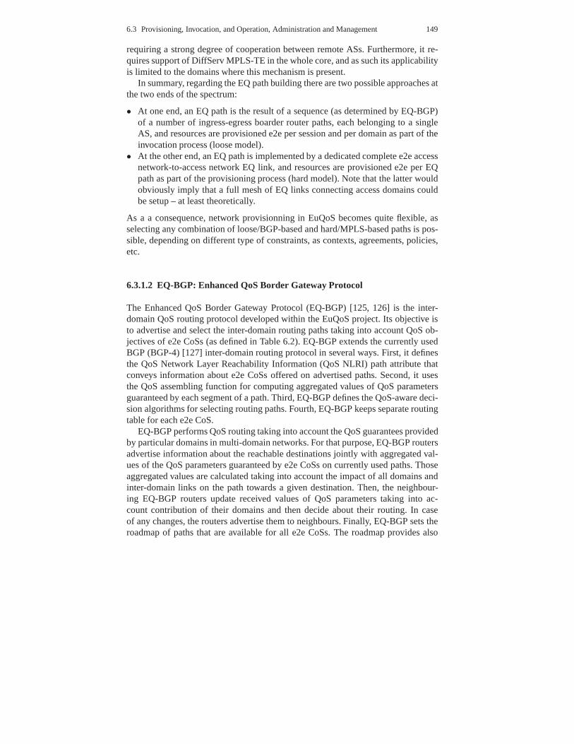
6.3.1.2 EQ-BGP: Enhanced QoS Border Gateway Protocol
The Enhanced QoS Border Gateway Protocol (EQ-BGP) [125, 126] is the inter-domain QoS routing protocol developed within the EuQoS project. Its objective isto advertise and select the inter-domain routing paths taking into account QoS ob-jectives of e2e CoSs (as defined in Table 6.2). EQ-BGP extendsthe currently usedBGP (BGP-4) [127] inter-domain routing protocol in severalways. First, it definesthe QoS Network Layer Reachability Information (QoS NLRI) path attribute thatconveys information about e2e CoSs offered on advertised paths. Second, it usesthe QoS assembling function for computing aggregated values of QoS parametersguaranteed by each segment of a path. Third, EQ-BGP defines the QoS-aware deci-sion algorithms for selecting routing paths. Fourth, EQ-BGP keeps separate routingtable for each e2e CoS.
EQ-BGP performs QoS routing taking into account the QoS guarantees providedby particular domains in multi-domain networks. For that purpose, EQ-BGP routersadvertise information about the reachable destinations jointly with aggregated val-ues of the QoS parameters guaranteed by e2e CoSs on currentlyused paths. Thoseaggregated values are calculated taking into account the impact of all domains andinter-domain links on the path towards a given destination.Then, the neighbour-ing EQ-BGP routers update received values of QoS parameterstaking into ac-count contribution of their domains and then decide about their routing. In caseof any changes, the routers advertise them to neighbours. Finally, EQ-BGP sets theroadmap of paths that are available for all e2e CoSs. The roadmap provides also

150 6 The EuQoS System
Fig. 6.6 Example of EQ-BGP operation
values of QoS parameters that are guaranteed between each pair of source and des-tination prefixes.
Figure 6.6 shows an example of how QoS routing information iscomputed andadvertised in the network using EQ-BGP. For the sake of simplicity, we assumea simple network consisting of three domains A, B and C that support only onee2e CoS. Each EQ-BGP router is aware of the values of the QoS parameters thatare assured inside its domain (QA, QB or QC depending on the domain) as wellas on its corresponding inter-domain link (QA−>B or QB−>A, respectively). Thosevalues should correspond to the maximum admissible load that are allowed by theadmission control function. The actual values should be fixed during the networkprovisioning process taking into account details of domainconfiguration, used tech-nology, provider policies, etc. The values of QoS parameters typically change atprovisioning time scales, e.g. in the order of days or weeks,so route changes due tofrequent variations of the QoS values are not expected.
Now, let us consider the case when Domain C advertises a new prefix, saypre fc.Then, the routing information is propagated towards DomainA through DomainB. Figure 6.6 shows the routing tables of the border EQ-BGP routers along thepath. During this process EQ-BGP routers aggregate the values of the QoS param-eters taking into account the QoS contribution of particular domains as well as theinter-domain links on the path towardspre fc advertised by Domain C. For example,domain A learns the e2e QoS path towards the destinationpre fc, with QoS cor-responding toQA⊕QA−>B⊕QB ⊕QB−>C ⊕QC for considered CoS, wherein theoperator⊕ denotes QoS assembling function. Taking into account that QoS param-eters used by the e2e CoSs can be treated as additive, we use a simple sum function.
The values of QoS parameters are advertised using the QoS Network LayerReachability Information (NLRI) path attribute presentedin Figure 6.7. The at-tribute begins with the attribute header that contains flags, type indicator and theattribute length. The flags are used to inform routers that information carried inthe QoS NLRI attribute is optional, non-transitive, and complete. The main part ofthe attribute contains a number of structures describing particular e2e CoSs. Eachstructure covers the e2e CoS identifier and three fields including IP Packet Transfer
6.3 Provisioning, Invocation, and Operation, Administration and Management 151
Fig. 6.7 Format of the QOS Network Layer Reachability Information path attribute
Delay (IPTD), IP Packet Delay Variation (IPDV) and IP PacketLoss Ratio (IPLR)parameters. Values of IPTD, IPDV are expressed inµsec, while IPLR is carried inthe exponent form:−1000∗ log10(IPLR).
EQ-BGP uses the QoS-aware decision algorithm. It allows therouters to comparethe paths going toward a given destination and then to select“the best” one from theviewpoint of QoS objectives of particular e2e CoSs. The algorithm adds a new stepin the routing decision process that evaluates the Degree ofPreference (DoP) factorbased on the values of QoS parameters carried in the QoS NLRI attributes. Thedegree of preference is used before the path length criterion. So, EQ-BGP will firstconsider the QoS level offered by the available paths and if this criterion does notdecide, the router will select the shortest path. The next decision steps are the sameas in case of the BGP-4 protocol.

152 6 The EuQoS System
6.3.2 Invocation Process
This section presents the invocation process in the EuQoS system, explaining thesignalling chain, the devices and functions triggered in each server involved in asession establishment.
6.3.2.1 Invocation in the Service Plane
The application invocation and signalling phase is used to trigger the application-to-application negotiation and then, if positive, to trigger the network invocationprocess described in 6.3.2.2.
Taking into account that some applications already have different applicationsignalling, such as H323, SIP or any other ad-hoc protocols,EuQoS proposes a newapplication level architecture that avoids the restriction of using EuQoS applicationsignalling based on SIP as the only way to interact with the EuQoS network server.The key point of this approach has been to define a “QoS on-demand” service.
Two reference points are being defined to ask for the e2e QoS on-demand service:
• An interface provided by AQ-SSN to the EuQoS clients allows the clients to askfor an e2e QoS request. This interface is implemented using SOAP.
• the RM Service Access Point API (EQ-SAP) for trusted legacy terminals (e.g.,as it is proposed in the Home Gateway Initiative) or for any other allowed entity.
It is important to note that this approach makes the clients able to ask directly forQoS parameter reservation to the EuQoS system (that means, the user asks for ane2e CoS for a set of flows, and the user provides its credentials to be authorised andcharged) after obtaining the IP address and ports to be used by the callee side.
As explained in the general architecture description (6.2.2), several scenarios canuse this architecture. More details can be found in [128].
• EuQoS aware application using QoS-on-Demand service• QoS-on-Demand services used by administrators for legacy applications, via a
web interface.• Trusted terminals, as home gateways, using EQ-SAP to reserve QoS.
In order to support these scenarios, the main goal of this newapproach is to clearlyspecify the interfaces exposed by the AQ-SSN and RM, QoS on demand and EQ-SAP services, respectively. Table 6.3.2.1 tries to sum up the main characteristics ofthese reference points.
6.3.2.2 Invocation in the Control Plane
A straightforward invocation process could be as follows:

6.3 Provisioning, Invocation, and Operation, Administration and Management 153
QoS on demand service EQ-SAPService provider AQ-SSN RMService client QCM and user administrator via web
interfaceAQ-SSN and trusted terminals
Information This service must support request- This service must support request-exchange response transactions and shall response transactions and shallrequirements provide a reliable delivery of the mes-
sages.provide a reliable delivery of the mes-sages.
Information Requests: Requests:flows exchanged
• Perform Reservation• Modify Reservation• Terminate Reservation
Responses:
• QoS Answer to perform requests.• Result of the reservation termina-
tion
• Perform Reservation Commit• Modify Reservation• Terminate reservation
Responses
• Resources available to reserve andmodify requests
• No response to terminate request.It is considered that the connectionrelease is always successful
Table 6.1 Brief description of EuQoS main interfaces
• All domains involved in the EQ path must be asked to reserve the resourcescorresponding to the connection. This would require a high amount of signallingtraffic and a high number of configuration on network equipment.
• The resources in each domain are reserved sequentially. This is not optimal if thesetup time is a critical performance parameter, and would have a higher impactif the reservation of all the flows belonging to the same session would be alsoperformed sequentially.
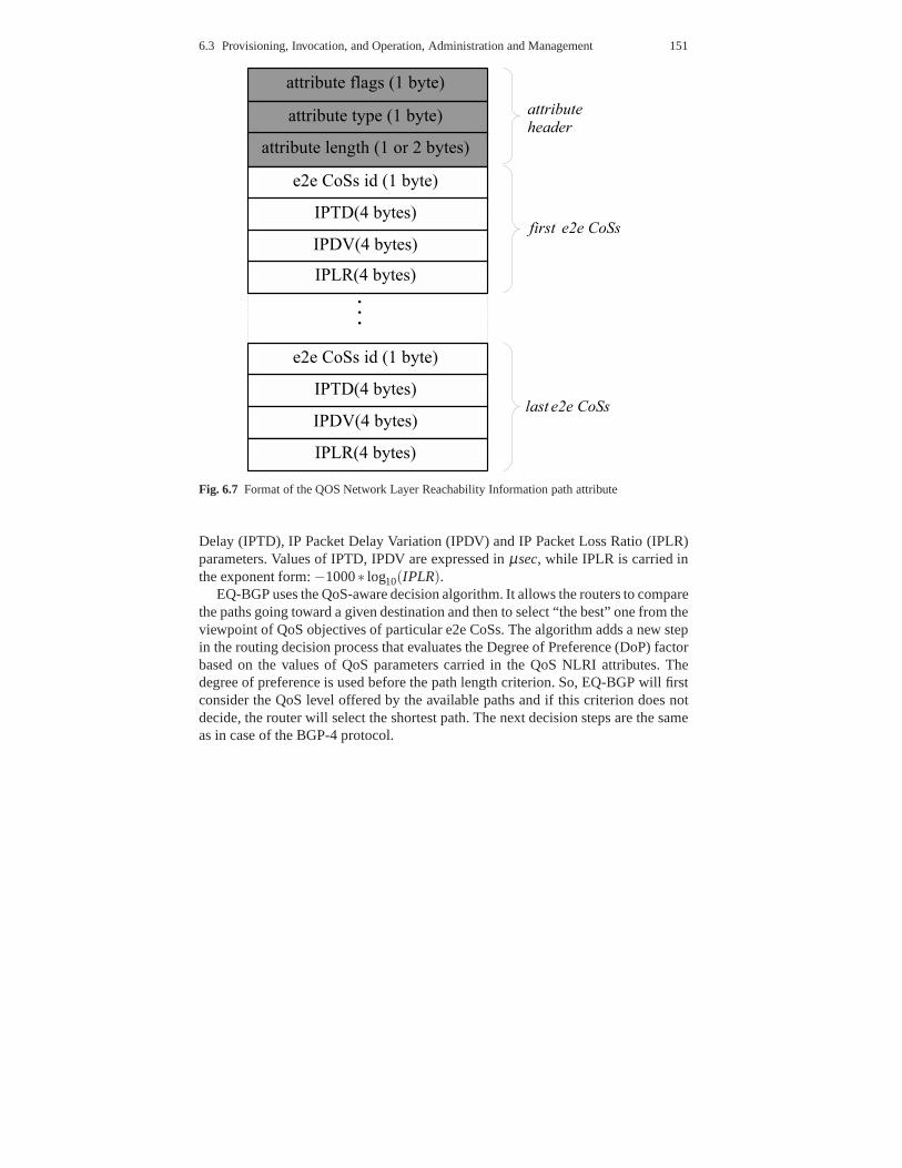
To address the first problem, the hard model has been implemented in the EuQoSsystem (see section 6.3.1.1). The configuration of transit domains is performed onlyduring the provisioning process instead of during the invocation process. In this way,the signalling load is reduced and the configuration of network equipment in corenetworks that are supposed to aggregate the traffic from different access networksis not performed during the invocation process. If we consider the simple scenarioshown in Fig. 6.8 to explain the invocation chain, the transit domain AS1 will not beasked to reserve resources during invocation process sinceaccess networks 1 and 2will see the EQ path as a link with a specific capacity.
Regarding the second problem, the invocation chain scheme has been designedso that to perform as many actions as possible in parallel.
When the AQ-SSN at the caller side receives the request to establish a new Eu-QoS session, it can ask the RM to reserve all connections fromboth directions (callerto callee side or callee to caller) in parallel, without waiting for the first QoS connec-tion request response. The RM will process these requests inparallel triggering all
154 6 The EuQoS System
Fig. 6.8 Invocation scenario
Fig. 6.9 Invocation sequence diagram
the domains involved in the EQ path. The RM located at the caller side will receiveall requests needed to reserve the resources for unidirectional flows.
In this scenario two cases can be distinguished, depending on the source IP ad-dress of the data flow:
1. The source IP address of the data flow belongs to the (caller) RM administra-tive domain. In this case the RM receives in the EQ-SAP interface the requestto reserve resources for a flow whose IP address belongs to itsadministrativedomain. In order to allow the parallel configuration of network equipment at theaccess networks, the RM forwards the requests to reserve resources to the nextdomain after performing the CAC algorithm specific for each technology. TheRM effectively reserves the resources while other domains are performing thechecking/configuration of their resources. In order to assure that the client hasan e2e path with guaranteed QoS, each domain will only send back the confir-mation response after receiving the confirmation of the reserved resources fromits RA. The sequence of exchanged messages is shown in Fig. 6.9. As it canbe seen, this scheme allows configuring in parallel resources in both access net-

6.3 Provisioning, Invocation, and Operation, Administration and Management 155
Fig. 6.10 Destination initiated scenario
works. This is interesting, because if, e.g., the first access network is UMTS (thetime to establish a session is around 5-10s) and the second isa WiFi domain (thiswould require around 1-2s), the time required to the configuration of the WiFiequipment would not be added to the time to establish the UMTSsession.
2. The source IP address of the data flow does not belong to the RM1 administrativedomain. In this case the RM1 (caller side) must resend the request to the RM2(located at the callee side) and be aware of the result of the reservation. In orderto do that, the NSIS NOTIFY message will be used to transport the requestsand responses between the access RMs, as shown in Fig. 6.10. The connectionestablishment from access network 2 to access network 1 follows the descriptionpresented in the previous case.
6.3.2.3 Sometimes Per Flow Model
Taking into account the benefits and drawbacks of the loose and hard options men-tioned earlier, an intermediate solution has been proposed, named SomeTimes PerFlow (STPF). The details about the STPF model can be found in [129]. The STPFassumes that the resources provisioned for a given CoS in considered domains aredivided into two main parts, where one part is reserved only for handling the calls onthe basis of thehard modelscheme (as multi-domains EQ links) while the secondpart is handled by theloose modelscheme.
The resources designated to operate loosely per-flow can be used only when thereare no resources available in the corresponding hard EQ link. As a consequence,the majority of the call requests should use the hard model, and will not use thefull reservation scheme. The full reservation process is then used only for a certainpercentage of calls. In this way, it is expected to get high resource utilisation whilethe required signalling traffic will be noticeably reduced.
156 6 The EuQoS System
6.3.3 Operation, Administration and Management
In order to guarantee the QoS commitment, the EuQoS system performs two ac-tions: the first is the admission control, and the second is the monitoring of the EQpath. This second goal is the main goal of the OAM process. Monitoring is done bymeans of measurement and fault management.
The measurement sub-system allows the EuQoS system to verify that EQ pathsare not overbooked (i.e. the maximum allocated bandwidth corresponds, more orless, to the sum of reserved bandwidth). The fault management sub-system allowsverification of the EQ path continuity and takes care of device, node, and link fail-ures. These two sub-systems interact with the invocation process (so that the CACadjusts the admission control threshold), and the provisioning process (in order tore-compute the EQ path in case of node or link failure). This path protection canbe improved by setting up some backup paths by means of a Fast Re-Route (FRR)mechanism when EQ paths are built with MPLS-TE in the hard model.
In order to monitor the provided QoS, the MMF/MMS functions of the EuQoSsystem monitor the QoS parameters (IPLR, IPTD and IPDV) and the used band-width per aggregate. In order to do that, different probes are distributed in eachEuQoS domain and the information is reported to all functions involved in the in-vocation processes. Moreover, the MMF/MMS manages a set of thresholds for QoSparameters and global link utilisation. In case that any of these thresholds is over-loaded, an alarm event is generated.
Moreover, for the loose model, the monitoring system will compare the actualEQ-BGP routes with the Service Level Agreement (SLA) information being man-aged by the TERO module, in order to check that the information agreed betweendifferent operators corresponds to the real usage of the network.
The final specification of the functionalities to be covered by the MMF/MMSsubsystem of the EuQoS system are described in [130].
6.4 End-to-End Classes of Service in Heterogeneous Networks
This section describes the framework defined in the EuQoS system for providing atthe application and at the network layers e2e QoS for heterogeneous multi-domainnetworks. It presents how connections requiring QoS are established between com-municating hosts attached to different access networks. Access networks can be builton different technologies such as xDSL, UMTS, LAN, WiFi, MPLS ad Satellite, andcan be interconnected by many IP-based core domains. Furthermore, implementingthe framework means to transfer packets while guaranteeingsome QoS parameters,i.e. packet delay (IPTD), variation of the packet delay (IPDV) and packet loss ratio(IPLR). The proposed solution should assure that the optimal values of the aboveparameters are satisfied. The EuQoS approach establishes inthe network a numberof, so called, Classes of Services (CoSs). The term of Class of Service (CoS) is aservice the network offers to traffic streams ([14], [76], [131], [132], [133]).

6.4 End-to-End Classes of Service in Heterogeneous Networks 157
The rest of this section is organised as follows. Section 6.4.1 describes the imple-mented e2e CoSs in EuQoS explaining their roles and their QoSobjectives. Section6.4.2 explains the main assumptions that have been made for QoS mechanisms andalgorithms required for implementing e2e CoSs in the underlying technologies. Itfocuses on the specification of generic CAC (Connection Admission Control) algo-rithms that is the key-element for providing QoS guaranteesat the network level.Finally, Section 6.4.3 gives the basic approaches for providing e2e CoSs in each un-derlying technologies as IP inter-domain links, xDSL, LAN/Ethernet, WiFi, UMTS,MPLS and satellite.
6.4.1 End-to-end Classes of Service in EuQoS
EuQoS assumes that a user can use 6 e2e CoSs (e2e CoSs) that differ in their QoSobjectives. A specific CoS is used for handling packets generated by a given type ofapplication as, for example, VoIP connections. Table 6.2 shows the complete set ofthe CoSs as proposed for the DiffServ architecture [20], [134]). In EuQoS, a subsetof these CoSs has been implemented (marked in bold in Table 6.2), as follows:
• The Telephony e2e CoS belongs to the Real Time (RT) class and is mainly ded-icated for handling VoIP, emitting streaming traffic of CBR or VBR type. ThisCoS requires strict QoS guarantees with respect to the selected values of IPTD,IPDV and IPLR.
• The RT Interactive e2e CoS: this class belongs to the RT classand is mainly ded-icated for handling VTC (Video-Tele Conferences) as well asinteractive gamessuch as NEXUIZ [135] by emitting streaming traffic of CBR or VBR type. ThisCoS requires strict QoS guarantees with respect to assumed values of IPTD,IPDV and IPLR. This CoS and Telephony CoS differ in packet lengths (rathersmall for VoIP compared to VTC) and required bandwidth (again, smaller forVoIP) while the required QoS level is similar.
• The Signalling e2e CoS belongs to the RT class and is mainly dedicated for han-dling application, routing and network signalling traffic.This CoS provides strictguarantees with respect to assumed values of IPTD, IPDV and IPLR. This e2eCoS can guarantee fast connection set-up times. More details about dimensioningthis class are in [136].
• The Multi-Media (MM) Streaming e2e CoS belongs to the NRT (Non RT) classand is dedicated for handling streaming traffic (CBR or VBR) generated by VoD(Video on Demand) applications. This e2e CoS provides strict guarantees withrespect to assumed values of IPTD and IPLR, but the value of IPDV is not critical.
• The High Throughput Data (HTD) e2e CoS belongs to the NRT class and isdedicated for handling elastic traffic generated by TCP-controlled applications(as in medical applications as Medigraf [137]). As for MM Streaming, this CoSprovides strict guarantees with respect to IPTD and IPLR, while the value ofIPDV is not critical.

158 6 The EuQoS System
End-To QoS Objectives EuQoS ApplicationsTreatment -End Medigrafaggregate Service IPLR Mean IPDV NEX- VoIP VTC VoD Collabo- Data
Class IPTD UIZ VTC ration transfer ChatNetwork
CTRL Control 10−3 100 ms 50 ms100/350 ms
Telephony 10−3 (local/long 50 ms Xdistance)
Signalling 10−3 100 ms UReal MM Con-Time ferencing 10−3 100 ms 50 ms
100/350 msRT 10−3 (local/long 50 ms X X X
Interactive distance)Broadcast
video 10−3 100 ms 50 msMM 1 s
Non-Real Streaming 10−3 non critical U XTime / Low Latency
Assured Data 10−3 400 ms UElastic OAM 10−3 400 ms U
HighThroughput 10−3 1 s U X
Data non criticalStandard U U U X
Elastic LowPriorityData U U U
Table 6.2 Mapping of EuQoS Applications to Classes of Service
e2e CoS DSCP NameDSCP ValueTelephony EF 101110Signalling CS5 101000
RT Interactive CS4 100000MM Streaming AF3x 011xx0*
High Throughput Data AF1x 001xx0*Standard DF 000000
Table 6.3 DSCP codes/names for e2e CoSs in EuQoS (* xx∈ {01,10,11})
• The Standard e2e CoS provides best effort and it means that noguarantee isprovided for the IPTD, IPDV and IPLR parameters but the network allocates agiven amount of bandwidth to this CoS.
The network will recognise that an IP packet belongs to a given e2e CoS byanalysing the DSCP (Differentiated Services Code Point) field in IPv4 or the Typeof Service (TOS) field in IPv6. The appropriate code in the packet is assigned bythe user equipment and again by the first network element thathandles the packet.Table 6.3 shows the DSCP codes/names corresponding to the e2e CoS in EuQoS asproposed in [20].
Figure 6.11 shows the concepts followed for implementing the above specifiedset of CoSs, regarded as globally known by the users (and the user QoS-aware appli-cations). A user who wants to use a given application (VoD, VoIP etc.) activates itsQoS and submits its QoS request to the predefined e2e CoS, accordingly to the map-ping given in Table 6.2. In EuQoS, possible paths are EQ paths, and when the path
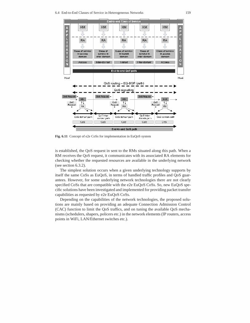
6.4 End-to-End Classes of Service in Heterogeneous Networks 159
Fig. 6.11 Concept of e2e CoSs for implementation in EuQoS system
is established, the QoS request in sent to the RMs situated along this path. When aRM receives the QoS request, it communicates with its associated RA elements forchecking whether the requested resources are available in the underlying network(see section 6.3.2).
The simplest solution occurs when a given underlying technology supports byitself the same CoSs as EuQoS, in terms of handled traffic profiles and QoS guar-antees. However, for some underlying network technologiesthere are not clearlyspecified CoSs that are compatible with the e2e EuQoS CoSs. So, new EuQoS spe-cific solutions have been investigated and implemented for providing packet transfercapabilities as requested by e2e EuQoS CoSs.
Depending on the capabilities of the network technologies,the proposed solu-tions are mainly based on providing an adequate Connection Admission Control(CAC) function to limit the QoS traffics, and on tuning the available QoS mecha-nisms (schedulers, shapers, policers etc.) in the network elements (IP routers, accesspoints in WiFi, LAN/Ethernet switches etc.).

160 6 The EuQoS System
6.4.2 QoS Mechanisms and Algorithms for Specification of e2eClasses of Service
The i-th (i = 1, ...,6) e2e EuQoS CoS is designed for handling streams having agiven traffic profile, i.e., to assure adequate packet transfer characteristics (maxi-mum allowed values forIPTDe2e,i , IPDVe2e,i andIPLRe2e,i ). Furthermore, the i-the2e CoS over heterogeneous multi-domain network needs a compatibleCoSj ,i foreach domainj along the e2e path (j = 1, ...,N; N is the number of different domainsalong the path), also expressed by the above mentioned threeparameters,IPTD j ,i ,IPDVj ,i andIPLRj ,i. Due to the additive properties of IPTD, IPDV and IPLR2, foreach i-th e2e CoS we have :
IPTDe2e,i =N
∑j=1
IPTD j ,i
IPDVe2e,i =N
∑j=1
IPDVj ,i
IPLRe2e,i∼=
N
∑j=1
IPLRj ,i (6.1)
Note, that in equations 6.1 for a given e2e CoS we take into account only theparameters that are specified.
The general principles used to design CoSs mean: (1) to allocate resources forthe considered class, (2) to apply QoS mechanisms (in network devices) for forcingrequired packet transfer characteristics, and (3) to limitthe traffic submitted to theseresources by an appropriate CAC.
Let us illustrate these rules by considering an e2e CoS that handles traffic streamsdescribed by a Peak Rate (PR) and requiring transfer characteristics not larger thanthe predefined valuesIPTDe2e, IPDVe2e andIPLRe2e. Let us also assume that afterthe provisioning process, the requirements for a given domain are the predefinedmaximum values of parameters IPTD, IPDV and IPLR.
Example: Designing CoS with predefined maximum values of parameters IPTD,IPDV and IPLR. The CoS handles the traffic streams with declared PRs.
(1) Allocation of resourcesThe required resources for the CoS are usually represented by the link capacity(C) and an associated buffer (B). The CoS is designed for handling packet streamsemitted by applications with similar traffic characteristics. So, for the sake of
2 For two domains withIPLR1 in domain 1 andIPLR2 in domain 2, the resultingIPLR isIPLR1+2 = IPLR1 + IPLR2− IPLR1∗ IPLR2. In practical cases,IPLR1+2 is aroundIPLR1 + IPLR2asIPLR1 ∗ IPLR2 << IPLR1 + IPLR2. Therefore it can be considered as additive.

6.4 End-to-End Classes of Service in Heterogeneous Networks 161
simplicity, we can assume that the applications generate the packets with constantlength (L). In this case, we can control IPDV by settingB andC, since:
IPDV =LBC
(6.2)
Furthermore, the commonly known condition in the case when anumber ofpacket streams is multiplexed on a single link is that the link utilisation shouldbe less than 1. The condition for maximum link utilisation, sayρmax, comes fromconstraints on IPLR or IPTD. The relations for IPLR and IPTD,derived from theanalysis of the M/D/1/B [138] and M/D/1 (e.g., [139]) respectively, are:
ρIPTD =2B
2B− ln(IPLR)(6.3)
ρIPTD =2(IPTD−Tprop− L
C)
2IPTD−2Tprop− LC
(6.4)
whereTprop represents propagation delay. Finally, we calculateρmax from:
ρmax= min[ρIPTD,ρIPTD] (6.5)
The term 6.3 dominates in the most practical cases and 6.4 occurs only whenthe links have large propagation delays and rather low capacity C, e.g. fora case whereTprop = 90ms, C < 4.4 MBps, B = 10 packets, IPLR = 10−3,L = 150BytesandIPTD = 100ms.
(2) To apply available QoS mechanisms in devices for forcing required packet trans-fer characteristicsThe set of QoS mechanisms that are available in network devices differs de-pending on the underlying technology. Anyway, at least for now, the referenceQoS mechanisms are specified as PHB mechanisms in the DiffServ architec-ture. Assuring the requested packet transfer characteristics is based on the typeof available schedulers. The preferred schedulers are Weighted Fair Queueing(WFQ) and Priority Queuing - Weighted Fair Queuing (PQ-WFQ)because theyassure isolation between CoSs, i.e., guaranteeing isolated buffer size and a givenpercentage of the total link capacity. So, the traffic belonging to a given CoS isgathered in a dedicated queue.
(3) Limiting the traffic submittedLimiting the traffic submitted to a given CoS can be obtained by applying thefollowing well known formula for peak rate allocation [138]
PRnew+K
∑i=1
PRi ≤ ρmaxC (6.6)
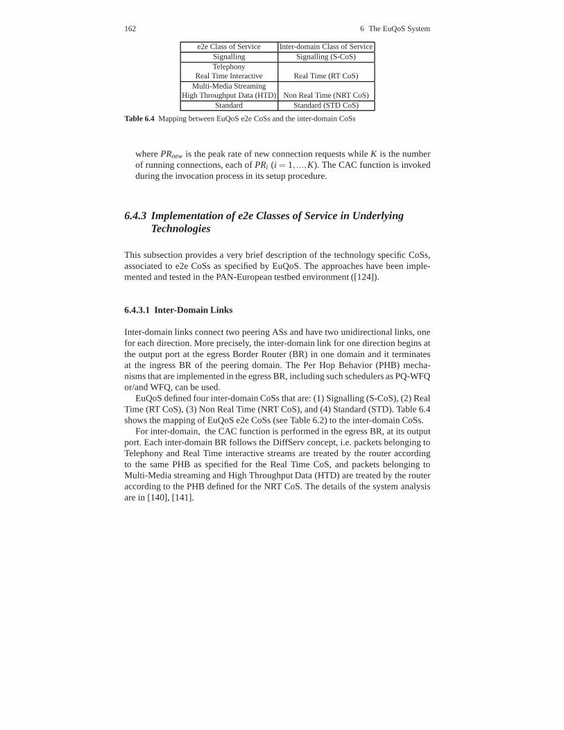
162 6 The EuQoS System
e2e Class of Service Inter-domain Class of ServiceSignalling Signalling (S-CoS)Telephony
Real Time Interactive Real Time (RT CoS)Multi-Media Streaming
High Throughput Data (HTD) Non Real Time (NRT CoS)Standard Standard (STD CoS)
Table 6.4 Mapping between EuQoS e2e CoSs and the inter-domain CoSs
wherePRnew is the peak rate of new connection requests whileK is the numberof running connections, each ofPRi (i = 1, ...,K). The CAC function is invokedduring the invocation process in its setup procedure.
6.4.3 Implementation of e2e Classes of Service in UnderlyingTechnologies
This subsection provides a very brief description of the technology specific CoSs,associated to e2e CoSs as specified by EuQoS. The approaches have been imple-mented and tested in the PAN-European testbed environment ([124]).
6.4.3.1 Inter-Domain Links
Inter-domain links connect two peering ASs and have two unidirectional links, onefor each direction. More precisely, the inter-domain link for one direction begins atthe output port at the egress Border Router (BR) in one domainand it terminatesat the ingress BR of the peering domain. The Per Hop Behavior (PHB) mecha-nisms that are implemented in the egress BR, including such schedulers as PQ-WFQor/and WFQ, can be used.
EuQoS defined four inter-domain CoSs that are: (1) Signalling (S-CoS), (2) RealTime (RT CoS), (3) Non Real Time (NRT CoS), and (4) Standard (STD). Table 6.4shows the mapping of EuQoS e2e CoSs (see Table 6.2) to the inter-domain CoSs.
For inter-domain, the CAC function is performed in the egress BR, at its outputport. Each inter-domain BR follows the DiffServ concept, i.e. packets belonging toTelephony and Real Time interactive streams are treated by the router accordingto the same PHB as specified for the Real Time CoS, and packets belonging toMulti-Media streaming and High Throughput Data (HTD) are treated by the routeraccording to the PHB defined for the NRT CoS. The details of thesystem analysisare in [140], [141].

6.4 End-to-End Classes of Service in Heterogeneous Networks 163
6.4.3.2 xDSL
In Digital Subscriber Lines (xDSL) networks four possible network points are can-didates to be the bottlenecks and need to be considered: the user xDSL modem (thegateway/Customer Premises Equipment CPE), the Digital Subscriber Line AccessMultiplexer (DSLAM) Aggregation Module, aggregation switch(es) and IP edgenode. However, in practice some simplifications can be made,depending on thespecific characteristics of the network technologies and the capabilities of particularelements.
It must be clearly stated that the evolution of DSL technology results today in arange of DSL standards (ADSL, ADSL2+, SHDSL, VDSL2, etc.) with different bitrates and architecture, affecting its major building block, DSLAM and BroadbandRemote Access Server (BRAS). The market demands for cost-effective, differen-tiated multimedia services provided in DSL networks. This forces the most popu-lar purely Asynchronous Transfer Mode (ATM) DSLAMs to be migrated to fullyIP-aware appliances with Ethernet uplinks in the aggregation segment. This makesDSL architecture more flexible and scalable. For instance, for distributed and smallgroups of subscribers IP-DSLAM may include the functionality of BRAS in a oneequipment. Considering the access part of DSL, one may find customer equipment,which is very simple and limited in functionality, devices without QoS mechanismsas well as fully configurable, DiffServ supporting, manageable gateways, mostlydeployed for business customers.
In order to achieve CAC for any variant of DSL access network,the CAC algo-rithm proposed in section 6.4.2 should be used for every IP-aware port with imple-mented QoS mechanisms. EuQoS considered the access and aggregation segmentsand focused on two network elements, the DSLAM (more precisely, the IP DSLAM,to implement the QoS mechanisms for IP traffic) and the IP edgenode (BRAS).The proposed CAC algorithms for the above elements differ intheir assumed typeof CoSs provision. In the aggregation segment, we can apply astatic partitioningof the link capacity between CoSs, as e.g. in the inter-domain links, while for theaccess segment we need to focus on link capacity sharing.
6.4.3.3 LAN/Ethernet
In switched Ethernet, the basic mechanism to differentiatetraffic is priority schedul-ing. According to IEEE 802.1Q [142] and 802.1p (part of the IEEE 802.1D [143])standards, the MAC layer has specified eight priority levels, each for a different Eth-ernet CoS. The priority level of a Ethernet frame is marked inthe 3 bit priority field.It is important to remark that eight priority levels are not available in all devicesand one can find equipment with four or even two priority levels. Table 6.5 showsthe proposal for mapping the e2e CoSs into Ethernet CoSs in the case where fourpriority levels are available.
The implementation of e2e CoSs in LAN/Ethernet is not trivial because of the or-ganisation of buffer management based on a shared buffer architecture. The packets

164 6 The EuQoS System
802.1p: values in priority fielde2e Class of Service Ethernet CoS in Ethernet frame header
Signalling Network Management 7 (highest)Telephony, RT Interactive Voice 6
Video 5MM Streaming,
High Throughput Data Controlled Load 4Excellent Effort 3
Standard Best Effort 0Undefined 2
Background 1
Table 6.5 Mapping between e2e CoSs and Ethernet CoSs
belonging to different CoSs share common buffer space. Thisspace is for all outputports. For providing isolation between CoSs and to control IPLR, it is proposed toexplore the following additional features of an Ethernet switch:
• The ability to identify traffic flows based on information at Layer 3 and 4, namelysource and destination IP addresses, ports and transport protocol (for EuQoS flowidentification) [144];
• The ability to perform data bit rate control on a per flow basis[145], [146];• The ability to perform random early packet discarding basedon the queue size
at the Ethernet output port (Weighted Random Early Detection (WRED) mecha-nism).
The CAC function is performed in two elements of the LAN/Ethernet accessnetworks, in the Ethernet Switch (ES) output port and in the Edge Router (ER). Theapplied CAC algorithm follows equation 6.6.
6.4.3.4 WiFi
The EuQoS approach for providing e2e CoSs in WiFi technologyis based on WiFiMulti-Media (WMM) extension [147] and exploits the Enhanced Distributed Co-ordination Access (EDCA) protocol defined in the extension.The EDCA protocolallows for differentiation of traffic using 4, so called, Access Categories (AC). How-ever, the EDCA itself does not provide strict QoS guaranteesas required for e2eCoSs. Then, our CoSs for WiFi use enhanced ACs with additional QoS mechanismsfor: (1) provisioning of network resources dedicated for particular CoSs such as val-ues of bandwidth, buffer size and parameters of the MAC protocol, (2) performingCAC , (3) conditioning the traffic generated by users (packets policing/shaping andmarking), and (4) providing packet scheduling at the IP layer in access point (AP).
Table 6.6 shows the mapping between e2e CoSs and WiFi CoSs. The WiFi CoSsreal time (RT), non-real time (NRT), signalling (SIG) and best effort (BE) are similarto the ones assumed for inter-domain links (see Table 6.4).

6.4 End-to-End Classes of Service in Heterogeneous Networks 165
e2e WiFi CoS QoS objectivesa
Class of Service (WMM AC) IPTD [ms] IPDV [ms] IPLRTelephony Real Time
RT Interactive (AC VO) 5 15 10−4
MM Streaming Non Real TimeHigh Throughput Data (AC VI) 10 - 10−4
SignallingSignalling (SIG)(AC VI) 10 - 10−4
Standard Best Effort (AC BE) - - -
a exemplary target values assumed in provisioning process
Table 6.6 Mapping between e2e CoSs and WiFi CoSs
The solution for WiFi WMM assumes that a single AP will handletraffic belong-ing to all WiFi CoSs (including best effort traffic), and the EDCA algorithm allowsto provide traffic separation between the CoSs.
6.4.3.5 UMTS
For UMTS, the main recognised problem is due to the lack of open interfaces forcontrolling the specific QoS mechanisms. As a consequence, for EuQoS it has beendecided to look at UMTS from two perspectives: a) UMTS as a black box whereavailable UMTS services are reused b) using an implicit, measurement-based, cell-load control approach that can be achieved by using traffic shaping for the connec-tions with assigned low priority (non-EuQoS connections submitted to backgroundCoS). This second approach also addresses the problem of defending the alreadyestablished EuQoS connections against QoS starvation. This problem is typical ofUMTS networks due to the frequent changes of radio channel conditions.
The first approach has been called Usage of built-in CAC from UMTS and thelatter Measurement based Open GPRS Gateway Support Node (OpenGGSN) CAC.
Usage of built-in CAC from UMTS
The main goal of the proposal is to take advantage of the built-in CAC from UMTS,which enables decision-taking based on cell load conditions (different among cells),and seamless resource reservation.
E2e CoSs are mapped to their corresponding UMTS traffic classes. Table 6.7shows the proposed mapping, taking into account the desirable solution and theavailability of commercial equipment.

166 6 The EuQoS System
EuQoS e2e CoS Ideal mapping to UMTS Feasible mappingTelephony Conversational Interactive (THP = 1)Signalling Background Background
Real Time Interactive Streaming Interactive (THP = 2)Multi-Media Streaming Interactive (THP=1) Interactive (THP=3)High Throughput Data Interactive (THP=2) Interactive (THP=3)
Standard Background Background
Table 6.7 Mapping between EuQoS and UMTS CoSs (THP- Traffic Handling Priority)
Measurement based OpenGGSN CAC
Although currently available UMTS deployments provide CoSs with strict QoSguarantees with respect to the values of parameters IPTD andIPDV, such featurescan not be fully exploited mainly due to some limitations in current operating sys-tems of computer Terminal Equipment (TE) that are connectedto UMTS by mobilephones (Mobile Terminal MT).
The problem to solve is the preservation of already established sessions with aguaranteed quality in presence of dynamic changes of the radio channel. In this case,even for the admitted connections we need additional mechanisms as continuousmonitoring and prioritised treatment in order to maintain the assumed QoS level forthem.
One feasible approach to prevent unexpected reconfiguration of resources is to re-duce transmission rates to accommodate low priority (non-EuQoS) users with worseradio channel characteristics. Anyway, non-EuQoS users with better radio chan-nel characteristics may maintain connections with unchanged bit rates if there areavailable resources. Some additional architecture components have been developedand deployed (protocol analyser with online session tracing and logging) to imple-ment this function. To do this, the OpenGGSN basic functionality was improved byadding standards compliant secondary Policy Decision Point (PDP) context man-agement.
6.4.3.6 MPLS (DiffServ-TE)
The QoS enforcement in the hard model is based on a two step approach. The firstone consists of provisioning and reserving bandwidth for anEQ link, i.e. an La-bel Switch Path (LSP) of a given CoS. The second one consists of preventing anexcessive amount of traffic to be routed through an LSP, whichis accomplished byperforming the usual CAC at the EQ link head-end before accepting the new session.
During the EQ link setup the bandwidth is guaranteed as follows:
• RSVP-TE reserves logical bandwidth for a given CoS. The remaining bandwidthfor the CoS is automatically advertised by the TE-routing protocol
• Each LSP of the same CoS shares the same queue, buffer and scheduler.

6.4 End-to-End Classes of Service in Heterogeneous Networks 167
e2e Class of Service DiffServ MPLS Class of ServiceSignalling CS5Telephony
Real Time Interactive EFMulti-Media StreamingHigh Throughput Data AF
Standard BE
Table 6.8 Mapping between EuQoS e2e CoSs and DiffServ MPLS CoSs
The PCE server compares the requirements of a tunnel againstthe remaining band-width of the CoS pool at each router as it performs the provisioning CAC. Thebandwidth is maintained by the TE-routing protocol to protect the resource poolagainst overbooking.
On a link, four classes will have a guaranteed bandwidth allocation: Signalling,Real-Time, Non Real-Time, and Class Default.
So the QoS guarantee first provisions and reserves bandwidthfor LSPs in a givenCoS, and second protects the LSP against too many flows by performing usual CACbefore accepting a new session.
6.4.3.7 Satellite
Scheme for Assuring QoS
The Satellite System provides an access network using the Digital Video Broad-casting - Satellite (DVB-S) and the Digital Video Broadcasting - Reverse ChannelSatellite (DVB-RCS) standards to carry out IP-based applications over geostation-ary satellite. The main concern in the satellite communication is to make an efficientuse of the scarce and costly resources. The asymmetric nature of the satellite com-munication architecture involves different mechanisms tomanage resource access.
Static and dynamic access techniques for satellites have been designed and in-tegrated into the Demand Assignment Multiple Access protocol (DAMA) for theDVB-RCS standard, in order to ensure a high utilization of the return link resourcesand offer QoS-oriented capacity assignment. DAMA access supports four main ca-pacity assignment types to reach its objective:
• Continuous Rate Assignment (CRA): Static and fully guaranteed rate capacity.• Rate Based Dynamic Capacity (RBDC): Guaranteed capacity upto RBDCmax
ceiling rate, but this requires dynamic requests (on-demand capacity).• Volume Based Dynamic Capacity (VBDC): The capacity is assigned when avail-
able in response to a request without any guaranty on assignment.• Free Capacity Assignment (FCA): Automatic allocation of unused capacity, no
guarantee and no requests are associated with this assignment type. Because ofthis automatic allocation, FCA type is not used in the EuQoS services.

168 6 The EuQoS System
EuQoS e2e Class of ServiceDAMA HighClasses Telephony RT Signalling MM ThroughputStandard
Interactive Streaming DataCRA X X X
RBDC X XVBDC X
Table 6.9 Mapping from EuQoS CoS to DVB-RCS access classes
Thus, the satellite lower layers are able to provide different types of service, whilekeeping efficient link resources utilization.
The CAC algorithm performed by the satellite RA in EuQoS benefits from theDAMA access scheme, but also from the information provided by the Network Con-trol Centre (NCC) concerning the agreement passed between the satellite terminaland the satellite system.
Table 6.9 summarises the mapping between RT, NRT and Standard CoSs and theDVB-RCS access classes.
6.5 EuQoS Enhanced Transport Protocol
6.5.1 Introduction
Past and new generations of transport layer protocols have been designed takinginto account only a subset of the requirements of multimediaapplications. Theserequirements are basically characterised by reliability and order constraints. Indeed,existing protocols have been designed to provide full orderand full reliability (i.e.TCP and SCTP) or no order and no reliability at all (UDP and DCCP). Even ifDCCP estimates network congestion by detecting packets outof order, it does notimplement any mechanism to deliver packets in any particular order.
At the network layer, standard (Best-Effort) service is still the predominant net-work service in the Internet, but new network services are proposed, as in EuQoS.Additionally, emerging wireless, mobile or satellite technologies present differentnetwork characteristics that should be considered by transport protocol designers,which means for instance to handle variable delay and packetloss rates induced byphysical channels.
All these reasons led us to propose an EuQoS Enhanced QoS-oriented transportprotocol, here noted as EQ-ETP, intended to provide optimised and differentiatede2e transport layer services for multimedia applications using the different availablenetwork layer CoSs.
Mechanisms implementing these transport layer services have to be designedsuch that they can respond to the various application requirements using the servicesprovided by underlying heterogeneous networks. Moreover,an Enhanced Transport

6.5 EuQoS Enhanced Transport Protocol 169
Protocol (ETP) should be designed within an extensible framework aimed at inte-grating future mechanisms intended to satisfy new requirements and/or to operateunder new networks.
The EuQoS Enhanced Transport Protocol is presented in detail in [124]. In thefollowing, a brief overview of the different service compositions for the EuQoSnetwork services is given.
6.5.2 Enhanced Transport Protocol Services for EuQoS
Enhanced Transport Protocols aim at fulfilling the multipleQoS requirements ofmultimedia applications over best-effort networks. EQ-ETP extends ETP for han-dling multiple CoSs. As the corresponding protocols and solutions need to be de-ployed over different network services, they should be implemented using a dy-namic architecture. A flexible and compositional architecture has been designed andimplemented in ETP in order to achieve a polymorphic deployment of various in-ternal mechanisms suited to manage the multiple QoS requirements of applicationsover the various classes of services provided by EuQoS. Thisarchitecture allowsQoS control and management mechanisms to be easily deployedand configured inorder to efficiently work together.
The modular approach of ETP has been defined in order to provide an effectiveway to satisfy a large range of applicative requirements by adequately composingand fine-tuning different well identified and designed transport layer building blocks(rate control, shaping, congestion control, flow control . .. ).
Given the nature of the EuQoS network classes of services, various possible com-positions have been developed for EQ-ETP in order to providethe most adequatetransport layer services regarding the temporal requirements of both streaming ap-plications and non-streaming applications. These compositions are presented in Ta-ble 6.10 where RC is Rate Control, EC is Error Control, TFRC and guaranteedTFRC (gTFRC) are congestion control mechanisms.
Streaming Non-Streaminge.g. VoD e.g. file transfer
Telephony - RT Interactive ETP [ RC ] ETP [ RC + EC ]MM Streaming - HTD ETP [ gTFRC ] ETP [ gTFRC + EC ]Standard ETP [ TFRC + TC ] ETP [ TFRC + EC ]
Table 6.10 EQ-ETP Service Composition for the EuQoS traffic classes
170 6 The EuQoS System
6.5.3 Services for Streaming/Non-Streaming Applications
In the following, the different EQ-ETP compositions for each of the EuQoS trafficclasses are presented. Two possible combinations of these are possible dependingon the nature of the applications. Streaming applications,which transmit one ormore multimedia flows, have specific requirements concerning error and time con-trol while non-streaming applications (generally speaking FTP like applications)require full reliability as their time constraints are of less importance than the onesof streaming applications.
6.5.3.1 Real Time Classes of Service (Telephony, RT Interactive)
In case of the Real Time Classes of Service, the application respects the traffic pro-file it has issued a reservation request for, reliability is guaranteed for the wholestream throughout the EuQoS system. In this context, as streaming applicationsare generally able to specify their bandwidth requirementsaccurately, the servicecomposition is limited to a dynamic binding to the UDP protocol. Optionally, theoperators might specify that a traffic shaper must be instantiated for shaping at thesending host. Thus, the load on the system routers is reduced. In this context, non-streaming applications generally have no loss tolerance. As the application mighthave underestimated its resource requirements, the transport services are composedof a shaper coupled to a SACK based error control to provide full reliability.
6.5.3.2 Non-Real Time Classes of Service (MM Streaming, HTD)
In case of Non Real Time Classes of Service, the application might exceed the trafficallowance that it has issued a resource reservation for. In such scenarios, the excesstraffic competes with other flows for which it has to respect certain friendliness inorder to avoid network collapse caused by congestion. This is achieved by means ofthe gTFRC module [148] as described in Section 5.4.
In the case of a non-streaming application, the zero loss tolerance is tackled bythe addition of a SACK based error control mechanism to ensure the correct, ordereddelivery of packets.
6.5.3.3 Standard Class of Service (Best Effort)
In the Standard Class of Service, all traffic must be shaped according to a conges-tion control algorithm in order to protect the network against congestion collapse. Inorder to improve the QoS provided to multimedia streams, a TC(Time Constraints)module will be used to offer fast retransmission mechanismswhen the time depen-dence of the packets (VoD Scenarios) [149]. In these scenarios, as non-streamingapplications have total reliability requirements, a SACK based error control is added

6.6 Multicast 171
to the composition. Furthermore, as time constraints are proper to streaming appli-cations, the TC module is not enabled for non-streaming applications.
6.6 Multicast
If a data packet should be sent to more than one destination, the sender usuallysends the same packet as many times as there are receivers interested in getting thedata. Therefore, multiple point-to-point connections areestablished. This one-to-one communication paradigm is called unicast . In the early days of the Internet,when email, FTP and remote host access were the main applications, there was noneed for other paradigms. But the Internet has changed a lot since then. Particu-larly, the appearance of the Web changed the situation. Now,pictures, movies andaudio/video streams are available over the network and their transmission uses upa significant portion of the available bandwidth. With today’s technology it is pos-sible to afford a unicast connection for everyone who wants to view a web page.However, to send live audio and video data, which needs a hugeamount of networkresources compared with web pages, it is not reasonable to have a single connectionto each receiver.
The drawbacks of the unicast approach for this kind of applications are evident.First, the source is required to hold a complete list of receivers and second, mul-tiple identical copies of the same data flow over the same links. Instead, data tomultiple destinations can be delivered using multicast [150]. Multicast allows thesource to send a single copy of data, using a single address for an entire group ofreceivers. Routers between the source and receivers use thegroup address to routethe data. The routers forward and duplicate data packets wherever a path to receiversdiverges.
IP knows three basic addressing modes. A unicast packet is sent to one receiver,a broadcast packet is sent to all hosts of a subnet and a multicast packet is directed toa group of receivers. Unicast and broadcast can be seen as multicast communicationwith the group of receivers containing one or all hosts respectively. A fourth modeis called anycast. This is a routing scheme which delivers the packet to the “nearest”(considering an appropriate metric) host out of a group of receivers.
The only difference between unicast and multicast addressing from the IP layer’spoint of view is the usage of special IP multicast addresses [151]. Unlike the unicastaddresses a multicast address is not assigned to a single host or network interface.The 32 bit address space of IPv4 (IP version 4) has been divided into five addressclasses A, B, C, D and E. The most significant bits of an addressdefine its class.The multicast address class is sometimes referred to as class D. Unlike the addressclasses A, B, and C the multicast address has no further structure. In case of the newIP version 6 (IPv6), all multicast addresses begin with the format prefixFF16 [152].
The Internet group management protocol (IGMP) [153] allowsthe hosts in theInternet to join and leave multicast groups. In order to reduce the amount of datasent over the network links, IGMP manages dynamic groups of multicast receivers.

172 6 The EuQoS System
The group management is done by the routers. Therefore, every router remembersthe hosts connected to its local interface(s), which are interested in receiving mul-ticast data and the respective multicast group IDs. IGMP provides the functional-ity for hosts to tell the routers in which multicast groups they are interested. Nowrouters can exchange the information about the multicast packets they have to re-ceive among themselves.
Another important group of multicast protocols is the groupof routing protocols.These protocols allow the routers to exchange information about multicast groupsand thus to build routes for each group. Examples for multicast routing protocols areprotocol-independent multicast (PIM) [154, 155], distance-vector multicast routingprotocol (DVMRP) [156], and multicast open shortest path first (MOSPF) [157].
IP-layer multicast has not been widely adopted by most commercial ISPs, andthus large parts of the Internet are still incapable of IP multicast more than a decadeafter the protocols were developed. As a result, the Multicast backbone (MBONE)was developed [158]. It consists of “islands” of multicast enabled networks in theInternet, connected through different types of tunnels. This concept has some draw-backs like the manual tunnel setup and the need for constant IP addresses. This isnot feasible for the average Internet user. However, with the increasing acceptance ofthe Internet Protocol Television (IPTV) some providers started to use multicast forthe transport of live video streams, at least internally. Itremains to be seen whetherthe support of IP multicast will be increased due to such new technologies.
6.6.1 Application Layer Multicast
Application layer multicast (ALM) is independent from the multicast support of theunderlying network. The multicast forwarding functionality is implemented exclu-sively at end systems. Logically, the end systems form an overlay network, and thegoal of application layer multicast is to construct and maintain an efficient overlayfor data transmission. Since application layer multicast protocols cannot completelyavoid the redundant transmission of data packets over the same link, they are lessefficient than IP multicast. The advantages are that ALM systems do not requireany modification of the underlying network components (e. g.routers) and can beimplemented on the application layer without any special operating system support.
Figures 6.12 and 6.13 show the differences of the data flow in IP multicast andapplication layer multicast networks. The solid black lines identify the physical net-work connecting hosts and routers, while the dashed lines denote the data packetflow.
The IP routers in Fig. 6.12 forward the multicast packets from the sender to thereceivers and duplicate the data if needed. The routers musttherefore support theIP multicast protocol. In Fig. 6.13, the peer-to-peer (P2P)overlay connections areidentified by a dotted and dashed line. In this environment nospecialised routers arenecessary. The packets are sent in unicast mode. The virtualdata flow follows theoverlay network structure, which does not necessarily correspond with the underly-
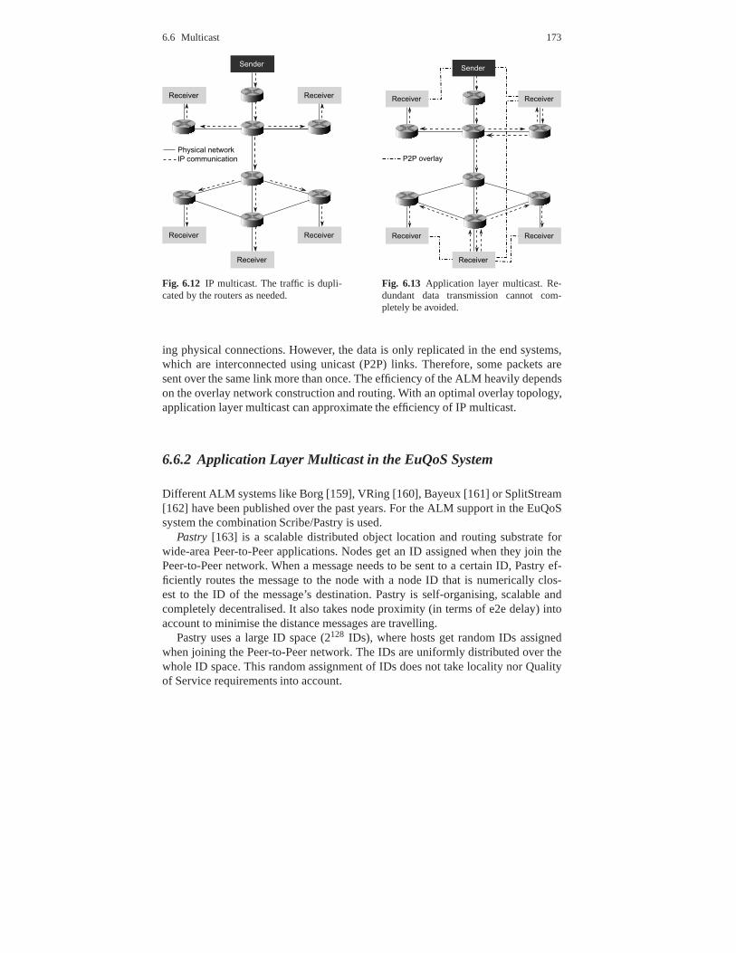
6.6 Multicast 173
Fig. 6.12 IP multicast. The traffic is dupli-cated by the routers as needed.
Fig. 6.13 Application layer multicast. Re-dundant data transmission cannot com-pletely be avoided.
ing physical connections. However, the data is only replicated in the end systems,which are interconnected using unicast (P2P) links. Therefore, some packets aresent over the same link more than once. The efficiency of the ALM heavily dependson the overlay network construction and routing. With an optimal overlay topology,application layer multicast can approximate the efficiencyof IP multicast.
6.6.2 Application Layer Multicast in the EuQoS System
Different ALM systems like Borg [159], VRing [160], Bayeux [161] or SplitStream[162] have been published over the past years. For the ALM support in the EuQoSsystem the combination Scribe/Pastry is used.
Pastry [163] is a scalable distributed object location and routingsubstrate forwide-area Peer-to-Peer applications. Nodes get an ID assigned when they join thePeer-to-Peer network. When a message needs to be sent to a certain ID, Pastry ef-ficiently routes the message to the node with a node ID that is numerically clos-est to the ID of the message’s destination. Pastry is self-organising, scalable andcompletely decentralised. It also takes node proximity (interms of e2e delay) intoaccount to minimise the distance messages are travelling.
Pastry uses a large ID space (2128 IDs), where hosts get random IDs assignedwhen joining the Peer-to-Peer network. The IDs are uniformly distributed over thewhole ID space. This random assignment of IDs does not take locality nor Qualityof Service requirements into account.

174 6 The EuQoS System
Pastry reliably routes messages identified by a key to the peer with the numeri-cally closest ID to the key. Routing uses less than⌈log2bN⌉ steps on average, whereN is the amount of nodes in the pastry network andb is typically a parameter with thevalue 4. Pastry guarantees eventual delivery unlessl/2 or more nodes with an adja-cent ID fail at the same time, withl , an even number parameter, being typically equalto 16. Pastry holds a routing table for each node with the sizeof (2b−1)⌈log2bN⌉+ lentries.
The routing tables are organised into⌈log2bN⌉ rows with each 2b−1 entries. Theentries of rown of a host’s routing table point to other nodes, which share the samefirst n digits of their ID with the host itself, but the digit at position n+1 has one ofthe 2b−1 possible values different from the digit at positionn+1 of the host’s ID.Each entry in the routing table consists of the node’s ID and its corresponding IPaddress. Additionally, each node maintains a list of nodes (IDs and IP addresses) ofthe numerically closest hosts in its leaf set (l/2 entries for the larger andl/2 entriesfor the lower IDs). A message is routed to the closest (in terms the network latency)host found in the host’s routing table whose ID matches the message’s key prefix.
Figure 6.14 shows a simplified example of how Pastry routing works. A messagewith the keye8cd is routed from a peer with ID3d1f to the peere8ca, which isnumerically closest to the message key. On each hop from the source peer to thedestination peer the message is sent to a peer whose ID matches more digits of themessage key prefix as it did match at the hop before. For the first routing hop startingfrom peer3d1f the message is sent to peere2ce, which shares the first digiteof themessage key. At the second hop, the message is routed to the peer with ID e831,which shares the first two digitse8. Finally, it is sent to peere8cawhich is the peerclosest to the message key and shares the first three digitse8cwith the key.
Fig. 6.14 Routing a message from peer3d1f to peere8cd.
6.6 Multicast 175
Scribe[164] builds on top of Pastry and is a large-scale decentralised ApplicationLevel Multicast infrastructure and supports a large numberof groups and a poten-tially large number of members for each group. Scribe balances the load on nodesto achieve short delays and less link stress.
Any Scribe node can join any multicast group (or topic in Scribe terminology)at any time. For each topic, one node is designated to disseminate the topic data inthe Pastry network. The node that is the root of the topic distribution tree has the IDnumerically closest to the topic ID. Scribe offers best-effort delivery of the multicastdata without guaranteeing that the order of the packets is maintained. The multicastor topic tree is built using a scheme similar to reverse-path-forwarding. A Scribenode, subscribing to a certain topic, sends a join message for this topic ID. Thismessage is routed using Pastry’s routing mechanism towardsthe topic’s root. Thenext node, to which the join message is routed, remembers that the node sending thejoin message is interested in data for this topic. If this intermediate node, called aforwarder, has not already joined this topic, it will itselfsend a join message to thesame topic. This process is repeated until a node is reached that has already joinedthe topic or is the root for the topic. Data dissemination within a topic is done fromthe root node of the topic towards the leaf nodes by followingall reverse paths tothe leaves. A side effect of this approach is that Scribe nodes forwarding messagesfor a certain topic have not necessarily interest in this topic.
6.6.3 Multicast Middleware
The EuQoS Multicast Middleware (MM in 6.15) [165, 166] is a solution to bridgeapplication layer multicast and IP multicast. It provides astandard IP multicast in-terface for the applications on the sender and receiver sideand uses ApplicationLayer Multicast for transporting the data.
The Multicast Middleware can be used with any ALM network, which offersthe standard multicast operations (subscription to a multicast group, receiving andsending multicast data). The typical P2P ALM network tries to approximate the ef-ficiency of IP multicast communication regarding link stress by using unicast com-munication. As discussed earlier, ALM is not able to totallyavoid sending redundantdata over the same physical link as IP multicast can.
The overlay network is usually built in a topology aware manner. Therefore,peers that are “close” to each other in terms of communication latency are directlyconnected. The P2P links are constantly monitored, which allows reacting to failuresin network communication or to failures of neighbour peers.
Eliminating the requirement for multicast support by the underlying networkmakes the use of Application Layer Multicast feasible for any kind of Internet users.The disadvantage of the ALM is the lack of standardisation. Each implementationhas its own API and addressing scheme. This prohibits already existing multicast-aware applications from using the ALM.

176 6 The EuQoS System
The IP multicast interface for the applications is usually offered by the operat-ing system. The operating system on the other side communicates with a multicastenabled router in the local network using IGMP as signallingprotocol. Sending IPmulticast traffic is not different from sending IP unicast traffic. The only differenceis the reserved address range, which denotes different multicast groups (groups ofmulticast traffic receivers). On the link layer, multicast traffic is handled differently.For example, in Ethernet the IP packets with a multicast group as a destination ad-dress get an Ethernet multicast address assigned.
To provide an IP multicast interface for the whole system (including servicesintegrated in the operating system’s kernel), the Multicast Middleware uses a vir-tual Ethernet device (also known as TAP device—a software analogy of a wire tap).The TAP interface is a special kind of network interface, which is seen by the op-erating system as a normal Ethernet device. However, instead of forwarding theEthernet frames to a hardware device, the TAP interface forwards the received Eth-ernet frames to a user-space process. On the other side, the TAP interface forwardsall Ethernet frames received from the user-space process asincoming frames to theoperating system’s kernel. TAP support exists for all majoroperating systems suchas UNIX/Linux, MacOS X and WIN32.
Using a TAP interface and the Multicast Middleware makes processing of mul-ticast traffic transparent to all applications. This includes the multicast functional-ity integrated in the operating system’s kernel. This approach does also not requireany modification of application code. Any IP multicast application can be supportedtransparently. Multicast traffic originating from an end system can be routed throughthe TAP device. This device forwards the packets (encapsulated in Ethernet frames)to a user-space process (the Multicast Middleware) for processing. The MulticastMiddleware acts as a multicast router by implementing IGMP and transporting themulticast data.
IP multicast enabled applications must subscribe to different multicast groupsto receive video broadcast announcements and audio/video streams. The multicastgroup subscription is usually a system call, which instructs the operating system’skernel to send IGMP membership report messages to the IP multicast router. In ourcase, the IGMP membership reports are sent via the TAP interface to the MulticastMiddleware. The Multicast Middleware interprets the IGMP membership reportsand notifies the neighbour peers about the changes in the multicast routing table.This information (depending on the multicast routing protocol used in the overlaynetwork) is propagated to other peers.
After a data packet has been sent by the application, it is forwarded by the op-erating system’s kernel to the appropriate multicast enabled network device (in thiscase the TAP device). The Multicast Middleware process receives the outgoing mul-ticast traffic via the TAP device. The received multicast traffic is then encapsulatedinto application layer multicast messages. The IP multicast destination address ofthe packets is translated into ALM addresses to which the messages are sent. Fig-ure 6.15 shows the message flow for sending and receiving datawith the MulticastMiddleware. The application (APP) is running on both end-systems for sending/re-

6.6 Multicast 177
ceiving the data stream. It uses the IP multicast interface of the Multicast Middle-ware that hides the ALM layer.
Fig. 6.15 Sending and receiving data using the Multicast Middleware (MM).
After receiving an encapsulated IP multicast packet by ALM,the Multicast Mid-dleware encapsulates the IP multicast packet into an Ethernet frame. The MulticastMiddleware then sends the Ethernet frame via the TAP interface to the operatingsystem’s kernel for processing. The operating system’s kernel delivers the data tothe application.
For the multicast data transport, any ALM protocol may be used. However, themapping of the IP multicast address space to the applicationlayer address schememight differ from one protocol to another.
Every IP multicast packet has a destination address out of the IP multicast addressrange. Most application layer multicast protocols implement their own addressingscheme. Depending on the protocol’s addressing scheme thisaddress range can besmaller, equal or larger than the IP multicast address range. In case of a larger orequal address range, multicast addresses can be mapped one-to-one to the appli-cation layer multicast addresses. For example the IP multicast address range canbe mapped to a consecutive address range of the same size in the application layermulticast protocol’s addressing scheme. In the case where the address range of theapplication layer multicast is smaller than the IP multicast address range, the IP mul-ticast addresses must be projected to the application layermulticast address range.
IP packets can be encapsulated in Application Layer Multicast messages. If thelength of an Application Layer Multicast message is larger than the IP packet length,the standard IP packet fragmentation can be applied to the packet in order to trans-port the packet through the overlay network. On reception offragmented IP packets,the Multicast Middleware should be able to reassemble them and to deliver them tothe TAP interface. The time to live (TTL) field of the transported packets should bereduced for each P2P hop. Packets with TTL=0 should not be forwarded.

178 6 The EuQoS System
6.6.4 Introducing QoS to Multicast Middleware
To satisfy the QoS requirements, the Multicast Middleware uses the EuQoS systemto setup network level QoS for the unicast links of the overlay network. Since theQoS requirements of the end systems within one IP multicast group can be hetero-geneous, it is necessary that the multicast tree is built in such way that the QoSrequirements and capabilities of end-systems are considered.
It is required that the QoS classes can be ordered and that they are independent ofthe path length. Such QoS classes can contain parameters such as bandwidth, jitterand maximum packet loss, but all the possible QoS classes must be comparable.Also note that in general there is no total order for a combination of such parametersand that the QoS parameter for maximum delay is not yet supported in the EuQoSsystem.
To provide QoS guarantees such as bandwidth or jitter in a multicast tree eache2e path from the root to a leaf node in the multicast tree musthave a monotonicallydecreasing QoS requirement. Figure 6.16 shows an example ofsuch a multicasttree. The path indicated as well as all other e2e paths of thismulticast tree hold thefollowing property: the QoS requirements (denoted by the thickness of the lines) arethe same or decreasing when following the intermediate hopsfrom the root node toa leaf node.
monotonicallydecreasing
QoS requirements
Root
Leaf
Fig. 6.16 Example of a multicast tree with monotonically decreasing QoS requirements from rootto leaf nodes. Thickness of the lines represents the degree of the QoS requirement in terms ofrequired bandwidth (thicker line = higher bandwidth requirement).
By analysing Scribe’s multicast tree construction, it becomes clear that the con-structed multicast tree does not necessarily hold this property. The reason for thisis that the e2e path from a leaf to the root is more or less randomly chosen, due torandom positioning of Pastry peers. Because Pastry’s default ID assignment does

6.6 Multicast 179
not take QoS requirements of peers into account, the multicast trees constructed byScribe are only by chance holding the described property. Itis sufficient that onlyone link in an e2e path does not support this property to violate the QoS require-ments for all nodes in the multicast tree below this link.
To enforce the construction of a QoS aware multicast tree using Scribe a dedi-cated Pastry P2P network is created for each multicast group. The reason for this isto have only peers interested in receiving the multicast data as potential forwarders.As a result, in this Pastry network only one topic exists. This topic ID is the highestpossible topic ID. Since the QoS requirements of a peer can behigher than its QoScapabilities, the QoS class is chosen, which corresponds tothe minimum of both.
As shown in Fig. 6.17, the ID space is partitioned into segments, one segmentfor each QoS class. Here, best-effort service is also considered to be a QoS class.The order of segments depends on the order of the QoS classes.The best-effortQoS class is located in the lowest segment and the highest QoSclass is located inthe highest segment. The assignment of IDs to joining peers depends on their QoSrequirements/capabilities. The peer ID is randomly chosenwithin the correspondingsegment of the ID space for the peer’s QoS requirements/capabilities.
Fig. 6.17 QoS aware distribution of peer IDs for Pastry.
There are different possibilities on how large the segmentsshould be. They donot necessarily have to be all of the same size and can for example decrease in sizetowards the root ID. The partitioning strategy has an impacton the construction ofthe multicast trees and therefore on how well and evenly balanced the overall trafficload will be distributed among the participating peers.

180 6 The EuQoS System
The routing path from a peer with a lower ID to a peer with a higher ID alwayscontains peers with increasing IDs. Because the root node ofthe multicast tree hasthe highest possible Pastry ID, the routing should always use peers with increasingPastry IDs for the hops on its path from leaf nodes towards theroot node.
By assigning peer IDs proportional to the peer’s QoS requirements, a construc-tion of Scribe multicast trees, holding the decreasing QoS requirement property foreach e2e path from the root to the leaves is ensured. For each node on the path fromthe root node to a leave node, the QoS requirement of the intermediate node is thesame or lower than the one of its parent node.
6.7 Telemedicine Application
6.7.1 Telemedicine – the Case for Application-Driven QoS
The concept of utility, as a measure of the perceived value orbenefit provided byQoS, is crucial to characterise the dependence of applications from QoS. For ex-ample, the utility of a standard mobile phone call is, up to a certain limit, relativelyimmune to QoS level variations – as long as end users are able to communicatein reasonable conditions. A certain level of QoS degradation is usually acceptable.Telemedicine applications are at the other end of the spectrum – near-perfect con-ditions are required by several application components (namely, real-time medicalvideo), and tolerance to fluctuations of quality as a result of network load is min-imal. The widespread deployment of such applications over public IP networks isoften hindered by the limited capability of service providers to guarantee the strictfulfilment of those requirements.
Given this wide range of application characteristics and requirements, a chal-lenge for service providers is how to handle such diversity both satisfactorily andefficiently. In theory, QoS could be handled by providing themost demanding QoSlevel to all customers and applications at all times - obviously, this would be eco-nomically unfeasible. Another solution could be the staticallocation of specific QoSprofiles to selected customers, thus ensuring that the required QoS treatment wouldbe provided by the network to those customers in all circumstances. In either case,flexibility and cost effectiveness would be quite poor. The dynamic application-driven approach proposed by EuQoS described below providesa solution to thisproblem.
6.7.2 Overview of Medigraf
Medigraf is a real-time H.323-based telemedicine application including a video-conference, collaborative facilities and an embedded multimedia repository to store

6.7 Telemedicine Application 181
patient data, medical images and reports. A typical Medigraf screen-shot is shownin Fig. 6.18.
The application is used in several scenarios – performing remote cooperativediagnosis on a regular basis, providing remote specialisedhealthcare assistance, en-abling collaboration between healthcare professionals inseveral scenarios, such asemergency situations and remote online training. The application offers significantgains in terms of efficiency and cost minimisation and is a valuable tool to providespecialised healthcare to populations in rural and sparsely populated areas, wherethe permanent availability of medical specialists is economically unfeasible.
Fig. 6.18 Typical Medigraf screenshot
The utility of the Medigraf application depends on the strict fulfilment of QoS pa-rameters. In fact, proper medical diagnosis is not compatible with less than optimalQoS conditions. On the one hand, video quality is crucial to enable a correct med-ical diagnosis. On the other hand, e2e synchronisation of the application graphicalelements requires stringent delay and jitter parameters.
Five basic traffic types are supported by Medigraf:
• Audio: used for audio communication. G.711 (PCMA, PCMU), G.728, G.722and G.723 codecs are supported.
• Video: used for face-to-face communication and transfer ofmoving imagesacquired from specialized medical equipment (e.g. echocardiography). H.261,H.263 codecs are supported with CIF (352x288), QCIF (176x144) or SQCIF(128x96) resolution.

182 6 The EuQoS System
• Data: used for file transfer, typically medical images.• Synchronisation: used for e2e synchronisation of graphical elements, e.g. point-
ers; requires strict compliance of e2e delay and jitter.• Application control: only minimal values of loss and delay are tolerated.
The difficulty to guarantee appropriate QoS conditions has been one of the issuesaffecting the deployment of Medigraf. In some cases, staticpre-reservation of net-work resources in specific time slots has been the solution tocircumvent this prob-lem. Unfortunately, this approach is not scalable and, in many circumstances, notrealistic. Perhaps most important of all, it is not viable inunplanned or emergencysituations, which coincidentally constitute one of the scenarios in which Medigrafwould be most valuable. Clearly, a solution capable of providing e2e guarantees ona dynamic “on-demand” basis would be an important added value to the application.
6.7.3 Medigraf Adaptation to EuQoS
One of the innovative aspects of the EuQoS solution for e2e QoS is the awarenessand active participation of the application in the QoS control process. We call an ap-plication EuQoS-aware if it is capable to explicitly request network resources and toactively participate in the QoS negotiation process by means of explicit signalling.This “EuQoS-awareness” requires the adaptation of the application or terminal toincorporate signalling capabilities, in order to inter-work with the EuQoS system.Two basic scenarios can be considered to integrate applications in the EuQoS sys-tem, as illustrated in Fig. 6.19:
1. Adapted legacy application: this refers to an application which was enhancedwith a software add-on named APP (see Fig6.19) to interwork with QCM. Theapproach followed in the case of Medigraf falls into this category, as describedbelow.
2. Proxy adapter: the strategy in this case is to leave the application untouched anduse an external proxy adapter.
As explained in section 6.2.2, QCM plays a pivotal role in theEuQoS architec-ture, as it provides a common standard interface between applications and the Eu-QoS system. Through QCM, applications are able to manage QoS-enabled sessionsand handle session events coming from the EuQoS system.
An EuQoS-aware version of Medigraf has been used to demonstrate and validatethe basic EuQoS concept of application-driven e2e QoS. The EuQoS application-driven approach provides Medigraf with the capability to request and control thenetwork resources it needs on a dynamic basis and provides a promising solutionto enable the widespread use of medical applications over public IP network infras-tructures.
The approach followed for adapting Medigraf is illustratedin Fig. 6.20. The orig-inal Medigraf application (“legacy” Medigraf) has been extended with a set of func-
6.7 Telemedicine Application 183
Fig. 6.19 Strategies for adaptation of applications
tions provided by the APP module, to enable inter-working with the EuQoS systemthrough QCM.
Fig. 6.20 Medigraf adaptation
APP incorporates the EuQoS awareness into the application and allows the com-munication with QCM and therefore the rest of the EuQoS system. This module hasbeen integrated into the application to enable the invocation of the QCM methods”performReservation” and ”closeReservation”.
Because Medigraf is natively based on H.323 signalling, a major design issuewas how to deal with the coexistence of the legacy Medigraf H.323 signalling planeand the EuQoS signalling plane. To minimise the adaptation effort, it was decidedto keep the H.323 plane untouched, moving the negotiation ofQoS parameters tothe EuQoS control plane and making sure that the result of theH.323 session setup

184 6 The EuQoS System
(namely, codec characteristics, TCP/UDP port numbers) is consistent with the Eu-QoS control plane negotiation. The APP module must guarantee consistency andsynchronisation between the two signalling planes, enforcing appropriate codec se-lection by means of hardware-specific functions, followingthe process illustrated inFig. 6.21.
Fig. 6.21 Medigraf - EuQoS synchronisation
6.8 Conclusions
This chapter presented the global architecture developed in the EuQoS project forproviding e2e QoS guarantees to Internet users. It addressed the problems of find-ing and providing e2e QoS paths between users connected through heterogeneousaccess network technologies.
A first prototype has been designed and implemented on a real testbed made upof GEANT, the NRENs in each participating countries, and using different accessnetwork technologies, in particular WiFi, LAN, xDSL, UMTS,Satellite and MPLS.
The prototype implements all approaches and address all keyproblems, as ap-plication negotiation, application QoS on demand capability, QoS and technologyindependent signalling, admission control, network provisioning, resource manage-ment and layered integration of coherent protocols. All this is provided using net-work technology independent and dependent solutions.
The evaluation has shown that the global architecture is quite general, is ableto integrate both a large set of technologies and a large set of independent waysof providing QoS. The network technology independent virtual layer proved to be

6.8 Conclusions 185
quite efficient in terms of designing, handling and abstracting all real technologiesand all dependent technology choices.
Efficiency and scalability have been proven, both in the access networks and inthe core networks, specially in the admission control function, solved in the lattercase by defining and using MPLS-based tunnels using PCE.
From the framework architecture adaptability and the results obtained, it followsthat the EuQoS system is really generic and able to integratea large set of solutionsguaranteeing QoS in a unique e2e EuQoS architecture.

References 255
References
1. R. Steinmetz and K. Nahrstedt,Multimedia Fundamentals: Medai Coding and Content Pro-cessing, 2nd ed. Prentice-Hall PTR, 2002, vol. 1.
2. ——,Multimedia Systems, 1st ed. Berlin, Germany: Springer Verlag, 2004.3. S. Floyd, “Connections with multiple congested gatewaysin packet-switched networks part
1: One-way traffic,”Computer Communications Review, vol. 21, no. 5, pp. 30–47, October1991.
4. M. Mathis, J. Semke, and J. Mahdavi, “The macroscopic behavior of the tcp congestionavoidance algorithm,”SIGCOMM Comput. Commun. Rev., vol. 27, no. 3, pp. 67–82, 1997.
5. ITU-T, “Itu t recommendation g.114: One-way transmission time.” 2003.6. ——, “Itu t recommendation g.1010: End-user multimedia qos categories.” 2001.7. T. Szigeti and C. Hattingh,End-to-End QoS Network Design: Quality of Service in LANs,
WANs, and VPNs (Networking Technology). CISCO Press, 2005.8. S. Keshav,An Engineering Approach to Computer Networking. Addison Wesley, 1997.9. R. Braden, D. Clark, and S. Shenker, “Integrated servicesin the internet architecture: an
overview,” RFC 1633, June 1994.10. S. Shenker and J. Wroclawski, “General characterization parameters for integrated service
network elements,” RFC 2215, September 1997.11. J. Wroclawski, “Specification of the Controlled-Load Network Element Service,” RFC 2211
(Proposed Standard), September 1997. [Online]. Available: http://www.ietf.org/rfc/rfc2211.txt
12. S. Shenker, C. Partridge, and R. Guerin, “Specification of Guaranteed Qualityof Service,” RFC 2212 (Proposed Standard), September 1997.[Online]. Available:http://www.ietf.org/rfc/rfc2212.txt
13. J. Solomon, “Applicability Statement for IP Mobility Support,” RFC 2005 (ProposedStandard), Oktober 1996. [Online]. Available: http://www.ietf.org/rfc/rfc2005.txt
14. S. Blake, D. Black, M. Carlson, E. Davies, Z. Wang, and W. Weiss, “An Architecture forDifferentiated Service,” RFC 2475 (Informational), Dezember 1998, updated by RFC 3260.[Online]. Available: http://www.ietf.org/rfc/rfc2475.txt
15. K. Nichols, S. Blake, F. Baker, and D. Black, “Definition of the Differentiated ServicesField (DS Field) in the IPv4 and IPv6 Headers,” RFC 2474 (Proposed Standard), Dezember1998, updated by RFCs 3168, 3260. [Online]. Available: http://www.ietf.org/rfc/rfc2474.txt
16. K. Nichols and B. Carpenter, “Definition of Differentiated Services Per Domain Behaviorsand Rules for their Specification,” RFC 3086 (Informational), April 2001. [Online].Available: http://www.ietf.org/rfc/rfc3086.txt
17. K. Nichols, V. Jacobson, and K. Poduri, “A per-domain behavior for circuit emulation in ipnetworks,”SIGCOMM Comput. Commun. Rev., vol. 34, no. 2, pp. 71–83, 2004.
18. B. Davie, A. Charny, J. Bennet, K. Benson, J. L. Boudec, W.Courtney, S. Davari,V. Firoiu, and D. Stiliadis, “An Expedited Forwarding PHB (Per-Hop Behavior),” RFC 3246(Proposed Standard), Marz 2002. [Online]. Available: http://www.ietf.org/rfc/rfc3246.txt
19. J. Heinanen, F. Baker, W. Weiss, and J. Wroclawski, “Assured Forwarding PHB Group,”RFC 2597 (Proposed Standard), June 1999, updated by RFC 3260. [Online]. Available:http://www.ietf.org/rfc/rfc2597.txt
20. J. Babiarz, K. Chan, and F. Baker, “Configuration Guidelines for DiffServ ServiceClasses,” RFC 4594 (Informational), August 2006. [Online]. Available: http://www.ietf.org/rfc/rfc4594.txt
21. L. Breslau, E. W. Knightly, S. Shenker, I. Stoica, and H. Zhang, “Endpoint admission control:architectural issues and performance,” inSIGCOMM ’00: Proceedings of the conferenceon Applications, Technologies, Architectures, and Protocols for Computer Communication.New York, NY, USA: ACM, 2000, pp. 57–69.
22. K. Ramakrishnan and S. Floyd, “A Proposal to add ExplicitCongestion Notification (ECN)to IP,” RFC 2481 (Experimental), Januar 1999, obsoleted by RFC 3168. [Online]. Available:http://www.ietf.org/rfc/rfc2481.txt

256 B Network Emulation Focusing on QoS-Oriented SatelliteCommunication
23. C. Cetinkaya, V. Kanodia, and E. W. Knightly, “Scalable services via egress admissioncontrol,” IEEE Transactions on Multimedia, vol. 3, no. 1, pp. 69–81, 2001. [Online].Available: citeseer.ist.psu.edu/cetinkaya01scalable.html
24. S. McCanne, V. Jacobson, and M. Vetterli, “Receiver-driven layered multicast,” inACM SIG-COMM, vol. 26, no. 4. New York: ACM Press, Aug. 1996, pp. 117–130.
25. V. Paxson, “Strategies for Sound Internet Measurement,” in 4rth Internet Measurements Con-ference, 2004.
26. V. Paxson, G. Almes, J. Mahdavi, and M. Mathis, “Framework for IP Performance Metrics,”RFC 2330, May 1998.
27. J. Mahdavi and V. Paxson, “IPPM Metrics for Measuring Connectivity,” RFC 2678, Sept.1999.
28. G. Almes, S. Kalidindi, and M. Zekauskas, “A One-way Delay Metric for IPPM,” RFC 2679,Sept. 1999.
29. I.-T. R. Y.1541, “Network Performance Objectives fo IP-based Services,” Review Jan 2005.30. G. Almes, S. Kalidindi, and M. Zekauskas, “A Round-trip Delay Metric for IPPM,” RFC
2681, Sept. 1999.31. ——, “A One-way Packet Loss Metric for IPPM,” RFC 2680, Sept. 1999.32. C. Demichelis and P. Chimento, “IP Packet Delay Variation Metric for IP Performance Met-
rics (IPPM),” RFC 3393, Nov. 2002.33. M. Mathis and M. Allman, “A Framework for Defining Empirical Bulk Transfer Capacity
Metrics,” RFC 3148, July 2001.34. I.-T. R. P.800.1, “Mean Opinion Score (MOS) terminology,” 2003.35. A. Takahashi, H. Yoshino, and N. Kitawaki, “Perceptual qos assessment technologies for
voip,” IEEE/Comm. Mag, vol. 42, no. 7, pp. 28–34, 2004.36. I.-T. R. G.107, “The E-model, a computational model for use in transmission planning,”
2003.37. I.-T. R. P.910, “Subjective video quality assessment methods for multimedia applications,”
1999.38. I.-T. R. P.862, “Perceptual evaluation of speech quality (PESQ): An objective method
for end-to-end speech quality assessment of narrow-band telephone networks and speechcodecs,” 2001.
39. D. L. Mills, “Network Time Protocol (Version 3) Specification, Implementation and Analy-sis,” RFC 1305, Mar. 1992.
40. D. Veitch, S. Babu, and A. Pasztor, “Robust synchronization of software clocks across theinternet,” inInternet Measurement Conference (IMC ’04), 2004.
41. N. Duffeld, “Sampling for passive internet measurement: A review,” Statistical Science,vol. 19, no. 3, pp. 472–498, 2004.
42. J. Quittek, T. Zseby, B. Claise, and S. Zander, “Requirements for IP Flow Information Export(IPFIX),” RFC 3917, Oct. 2004.
43. M. Crovella and B. Krishnamurthy,Internet Measurement. Infrastructure, Traffic, and Appli-cations. John Wiley & Sons, Ltd, 2006.
44. D. Harrington, R. Presuhn, and B. Wijnen, “An architecture for describing simple networkmanagement protocol (snmp) management frameworks,” RFC 3411, Dec. 2002.
45. “Lobster - Large-scale Monitoring of Broadband Internet Infrastructures,” http://www.ist-lobster.org.
46. N. G. Duffield and M. Grossglauser, “Trajectory samplingfor direct traffic observation,”IEEE/ACM Trans. Netw., vol. 9, no. 3, pp. 280–292, 2001.
47. T. Zseby, S. Zander, and G. Carle, “Evaluation of Building Blocks for Passive One-Way-Delay Measurements,” inPassive and Active Measurements Conference, 2001.
48. S. B. Moon, “Measurement and Analysis of End-to-end Delay and Loss in the Internet,”Ph.D. dissertation, University of Massachusetts, 2000.
49. J. Strauss, D. Katabi, and F. Kaashoek, “A measurement study of available bandwidth esti-mation tools,” inInternet Measurement Conference (IMC), 2003.

References 257
50. L. Lao, C. Dovrolis, and M. Y. Sanadidi, “The probe gap model can underestimate the avail-able bandwidth of multihop paths,”SIGCOMM Comput. Commun. Rev., vol. 36, no. 5, pp.29–34, 2006.
51. B. Melander, M. Bjorkman, and P. Gunningberg, “A New End-to-End Probing and AnalysisMethod for Estimating Bandwidth Bottlenecks,” inIEEE Globecom Global Internet Sympo-sium, 2000.
52. Q. Liu and J.-N. Hwang, “End-to-end available bandwidthestimation and time measurementadjustment for multimedia qos,” inICME ’03: Proceedings of the 2003 International Con-ference on Multimedia and Expo - Volume 3 (ICME ’03). Washington, DC, USA: IEEEComputer Society, 2003, pp. 373–376.
53. A. Pasztor and D. Veitch, “Active Probing using Packet Quartets,” inInternet MeasurementWorkshop, 2002.
54. R. Jain and S. A. Routhier, “Packet Trains-Measurementsand a New Model for ComputerNetwork Traffic,” IEEE Journal of Selected Areas in Communications, vol. SAC-4, no. 6, pp.986–995, 1986.
55. C. Dovrolis, P. Ramanathan, and D. Moore, “Packet-dispersion techniques and a capacity-estimation methodology,”IEEE/ACM Trans. Netw., vol. 12, no. 6, pp. 963–977, 2004.
56. “PlanetLab: An open platform for developing, deploying, and accessing planetary-scale ser-vices,” http://www.planet-lab.org/.
57. “Cooperative Association for Internet Data Analysis (CAIDA),” http://www.caida.org/.58. “Active Measurement Project (AMP),” http://amp.nlanr.net/.59. F. Georgatos, F. Gruber, D. Karrenberg, M. Santcroos, A.sanj, H. Uijterwaal, and R. Wilhem,
“Providing Active Measurements as a Regular Service for ISP’s,” in Proceedings of Passiveand Active Measurement, 2001.
60. “Evergrow Traffic Observatory Measurement InfrastruCture,” http://www.etomic.org/.61. “DIMES (Distributed Internet MEasurements & Simulations),” http://www.netdimes.org/.62. “Ever-growing global scale-free networks, their provisioning, repair and unique functions,”
http://www.evergrow.org/.63. S. Shalunov, B. Teitelbaum, A. Karp, J. W. Boote, and M. J.Zekauskas, “One-Way Active
Measurements Protocol,” RFC 4656, Sept. 2006.64. S. McCanne and V. Jacobson, “The BSD Packet Filter: A New Architecture for User-level
Packet Capture,” inUSENIX Winter, 1993.65. “perfSONAR - PERFormance Service-Oriented Network monitoring ARchitecture,” http:
//www.perfsonar.net.66. I. Miloucheva, P. Gutierrez, D. Hetzer, A. Nassri, and M.Beoni, “Intermon architecture for
complex QoS analysis in inter-domain environment based on discovery of topology and traf-fic impact,” in Inter-domain Performance and Simulation Workshop, Budapest, March 2004.
67. “Passive Measurement and Analysis (PMA),” http://pma.nlanr.net/.68. D. Awduche, J. Malcolm, J. Agogbua, M. O’Dell, and J. McManus, “Requirements
for Traffic Engineering Over MPLS,” RFC 2702 (Informational), Sept. 1999. [Online].Available: http://www.ietf.org/rfc/rfc2702.txt
69. E. Rosen, D. Tappan, G. Fedorkow, Y. Rekhter, D. Farinacci, T. Li, and A. Conta, “MPLSLabel Stack Encoding,” RFC 3032 (Proposed Standard), Jan. 2001, updated by RFCs 3443,4182. [Online]. Available: http://www.ietf.org/rfc/rfc3032.txt
70. L. Andersson, P. Doolan, N. Feldman, A. Fredette, and B. Thomas, “LDP Specification,”RFC 3036 (Proposed Standard), Jan. 2001. [Online]. Available: http://www.ietf.org/rfc/rfc3036.txt
71. H. Smit and T. Li, “Intermediate System to Intermediate System (IS-IS) Extensions forTraffic Engineering (TE),” RFC 3784 (Informational), June 2004, updated by RFC 4205.[Online]. Available: http://www.ietf.org/rfc/rfc3784.txt
72. D. Katz, K. Kompella, and D. Yeung, “Traffic Engineering (TE) Extensions to OSPFVersion 2,” RFC 3630 (Proposed Standard), Sept. 2003, updated by RFC 4203. [Online].Available: http://www.ietf.org/rfc/rfc3630.txt

258 B Network Emulation Focusing on QoS-Oriented SatelliteCommunication
73. R. Braden, L. Zhang, S. Berson, S. Herzog, and S. Jamin, “Resource ReSerVation Protocol(RSVP) – Version 1 Functional Specification,” RFC 2205 (Proposed Standard), Sept. 1997,updated by RFCs 2750, 3936, 4495. [Online]. Available: http://www.ietf.org/rfc/rfc2205.txt
74. D. Awduche, L. Berger, D. Gan, T. Li, V. Srinivasan, and G.Swallow, “RSVP-TE:Extensions to RSVP for LSP Tunnels,” RFC 3209 (Proposed Standard), Dec. 2001, updatedby RFCs 3936, 4420, 4874. [Online]. Available: http://www.ietf.org/rfc/rfc3209.txt
75. B. Jamoussi, L. Andersson, R. Callon, R. Dantu, L. Wu, P. Doolan, T. Worster, N. Feldman,A. Fredette, M. Girish, E. Gray, J. Heinanen, T. Kilty, and A.Malis, “Constraint-BasedLSP Setup using LDP,” RFC 3212 (Proposed Standard), Jan. 2002, updated by RFC 3468.[Online]. Available: http://www.ietf.org/rfc/rfc3212.txt
76. D. Grossman, “New Terminology and Clarifications for Diffserv,” RFC 3260 (Informa-tional), Apr. 2002. [Online]. Available: http://www.ietf.org/rfc/rfc3260.txt
77. F. Le Faucheur, L. Wu, B. Davie, S. Davari, P. Vaananen, R.Krishnan, P. Cheval,and J. Heinanen, “Multi-Protocol Label Switching (MPLS) Support of DifferentiatedServices,” RFC 3270 (Proposed Standard), May 2002. [Online]. Available: http://www.ietf.org/rfc/rfc3270.txt
78. F. L. Faucheur and W. Lai, “Requirements for Support of Differentiated Services-awareMPLS Traffic Engineering,” RFC 3564 (Informational), July 2003. [Online]. Available:http://www.ietf.org/rfc/rfc3564.txt
79. F. Le Faucheur and W. Lai, “Maximum Allocation BandwidthConstraints Model forDiffserv-aware MPLS Traffic Engineering,” RFC 4125 (Experimental), June 2005. [Online].Available: http://www.ietf.org/rfc/rfc4125.txt
80. F. Le Faucheur, “Russian Dolls Bandwidth Constraints Model for Diffserv-awareMPLS Traffic Engineering,” RFC 4127 (Experimental), June 2005. [Online]. Available:http://www.ietf.org/rfc/rfc4127.txt
81. W. Lai, “Bandwidth Constraints Models for Differentiated Services (Diffserv)-aware MPLSTraffic Engineering: Performance Evaluation,” RFC 4128 (Informational), June 2005.[Online]. Available: http://www.ietf.org/rfc/rfc4128.txt
82. F. Le Faucheur, “Protocol Extensions for Support of Diffserv-aware MPLS TrafficEngineering,” RFC 4124 (Proposed Standard), June 2005. [Online]. Available: http://www.ietf.org/rfc/rfc4124.txt
83. R. Stewart, Q. Xie, K. Morneault, and H. Schwarzbauer, “Stream Control Transmission Pro-tocol,” IETF, Tech. Rep. 2960, 2000.
84. T. Dierks and C. Allen, “The TLS Protocol,” IETF, Tech. Rep. 2246, 1999.85. D. Katz, “Router Alert Option,” IETF, Tech. Rep. 2113, 1997.86. M.Stiemerling, H.Tschofenig, C. Aoun, and E. Davies, “Nat/firewall nsis signaling layer
protocol (nslp),” IETF,” internet draft, 2006.87. D.Durham, J.Boyle, R.Cohen, S.Herzog, R.Rajan, and A.Sastry, “The COPS (Common Open
Policy Service) Protocol,” IETF, Tech. Rep. 2748, 2000.88. isox214, “ITU-T recommendation X.214 (11/95) information technology,” Nov. 1995.89. J. Postel, “Transmission control protocol: DARPA internet program protocol specification,”
IETF, Request For Comments 793, 1981.90. ——, “User datagram protocol (UDP),” IETF, Request For Comments 768, Aug. 1980.91. H.Schulzrinne, S.Casner, R. Frederick, and V. Jacobson, “An extension to the Selective Ac-
knowledgment (SACK) Options for TCP,” IETF, Task Force 3550, 2003.92. V. Jacobson and R. Braden, “TCP extensions for long-delay paths,” IETF, Request For Com-
ments 1072, Oct. 1988.93. V. Jacobson, R. Braden, and D. Borman, “Tcp extensions for high performance,” IETF, Re-
quest For Comments 1323, 1992.94. L. S. Brakno and L. L. Peterson, “TCP Vegas: End to End congestion Avoidance on a Global
Internet,”IEEE Journal on Selected Areas in Communications, no. 13, pp. 1465–1480, 1995.95. S. Floyd, T. Henderson, and A. Gurtov, “The newreno modification to tcp’s fast recovery
algorithm,” IETF, Request For Comments 3782, Apr. 2004.96. S. Floyd, J. Mahdavi, M. Mathis, and M. Podolsky, “An extension to the selective acknowl-
edgement (SACK) option for TCP,” IETF, Request For Comments2883, July 2000.

References 259
97. O. Ait-Hellal and E. Altman, “Analysis of tcp-vegas and tcp-reno,” inProc. of the IEEEInternational Conference on Communications - ICC, 1997, pp. 495–499.
98. V. Jacobson, L. Peterson, L. Brakmo, and S. Floyd, “Problems with arizona’s vegas,” mailinglist, end2end-tf, Tech. Rep., 1994, ftp://ftp.ee.lbl.gov/email/vanj.94mar14.txt.
99. L. Xu, K. Harfoush, and I. Rhee, “Binary increase congestion control for fast long-distancenetworks,” inProc. of IEEE INFOCOM, Mar. 2004, pp. 2514–2524.
100. S. Floyd, “Highspeed tcp for large congestion windows,” IETF, Request For Comments3649, Dec. 2003.
101. D. Katabi, M. Handley, and C. Rohrs, “Congestion control for high bandwidth-delay productnetworks,” inProc. of ACM SIGCOMM, 2002.
102. Y. Xia, L. Subramanian, I. Stoica, and S. Kalyanaraman,“One more bit is enough,” inProc.of ACM SIGCOMM, 2005.
103. K. Ramakrishnan, S. Floyd, and D. Black, “The addition of explicit congestion notification(ECN) to ip,” IETF, Request For Comments 3168, Sept. 2001.
104. P. Sinha, T. Nandagopal, N. Venkitaraman, R. Sivakumar, and V. Bharghavan, “WTCP: Areliable transport protocol for wireless wide-area networks,” Wireless Networks, vol. 8, no.2-3, pp. 301–316, 2002.
105. M. Gerla, M. Y. Sanadidi, R. Wang, A. Zanella, C. Casetti, and S. Mascolo, “Tcp westwood:congestion window control using bandwidth estimation,” inProc. of IEEE GLOBECOM,2001, pp. 1698–1702.
106. C. P. Fu and S. C. Liew, “Tcp veno: Tcp enhancement for transmission over wireless accessnetworks,”IEEE Journal on Selected Areas in Communications, vol. 21, no. 2, pp. 216–229,Feb. 2003.
107. R. S. et Al., “Sockets API extensions for stream controltransmission protocol (SCTP),”IETF, Internet Draft draft-ietf-tsvwg-sctpsocket-06.txt, Mar. 2003.
108. E. Kohler, M. Handley, and S. Floyd, “Datagram congestion control protocol (DCCP),” IETF,Request For Comments 4340, Mar. 2006.
109. S. Floyd and E. Kohler, “Profile for DCCP Congestion Control ID 2: TCP-like CongestionControl,” IETF, Request For Comments 4341, Mar. 2006.
110. S. Floyd, E. Kohler, and J. Padhye, “Profile for DCCP congestion control ID 3: TRFC con-gestion control,” IETF, Request For Comments 4342, Mar. 2006.
111. M. Handley, S. Floyd, J. Pahdye, and J. Widmer, “Tcp-friendly rate control (TFRC): Protocolspecification,” IETF, Request For Comments 3448, Jan. 2003.
112. S. Iren, P. D. Amer, and P. T. Conrad, “The transport layer: tutorial and survey,”ACM Com-puter Survey, vol. 31, no. 4, pp. 360–404, 1999.
113. S. Floyd, “Congestion control principles,” IETF, Request For Comments 2914, Sept. 2000.114. Y.-Q. Z. D. Wu, T. Hou, “Transporting real-time video over the internet: Challenges and
approaches,” inProc. of the IEEE, vol. 88, no. 12, Dec. 2000, pp. 1855–1875.115. V. Jacobson, “Congestion avoidance and control,” inProc. of ACM SIGCOMM, Stanford,
CA, Aug. 1988, pp. 314–329.116. R. Talluri, “Error-resilience video coding in the ISO MPEG-4 standard,”IEEE Communica-
tions Magazine, pp. 112–119, June 1998.117. Y. Wang and Q.-F. Zhu, “Error control and concealment for video communication: A review,”
in Proc. of the IEEE, vol. 86, no. 5, May 1998, pp. 974–997.118. M. Mathis, J. Mahdavi, S. Floyd, and A. Romanow, “TCP selective acknowledgment op-
tions,” IETF, Request For Comments 2018, Oct. 1996.119. J. Widmer, “Equation-based congestion control,” Diploma Thesis, University of Mannheim,
Germany, Feb. 2000.120. S. Floyd and K. Fall, “Promoting the use of end-to-end congestion control in the internet,”
IEEE/ACM Transactions on Networking, vol. 7, no. 4, pp. 458–472, 1999.121. P. Amer, C. Chassot, C. Connolly, P. Conrad, and M. Diaz,“Partial order transport service
for MM and other application,”IEEE/ACM Transactions on Networking, vol. 2, no. 5, 1994.122. L. Rojas-Cardenas, E. Chaput, L. Dairaine, P. Snac, andM. Diaz, “Video transport over
partial order connections,”Computer Networks, vol. 31, no. 7, pp. 709–725, Apr. 1999.

260 B Network Emulation Focusing on QoS-Oriented SatelliteCommunication
123. J.-P. V. A. Farrel and J. Ash, “A Path Computation Element (PCE)-Based Architecture,” TheInternet Society, Request For Comments 4655, Aug. 2006.
124. J. Enrıquez, M. A. Callejo, and et al., “EuQoS Architecture Deliverable D122,” 2007.125. A. Beben, “EQ-BGP: an efficient inter-domain QoS routing protocol,” inAINA ’06: Proceed-
ings of the 20th IEEE International Conference on Advanced Information Networking andApplications. Los Alamitos, CA, United States: IEEE Computer Society, Apr. 2006, pp.560–564.
126. X. Masip-Bruin, M. Yannuzzi, R. Serral-Gracia, J. Domingo-Pascual, J. Enriquez-Gabeiras,M. Callejo, M. Diaz, F.Racaru, G. Stea, E. Mingozzi, A. Beben, W. Burakowski, E. Mon-teiro, and L. Cordeiro, “The EuQoS System: A solution for QoSRouting in HeterogeneousNetworks,”IEEE Communications Magazine, vol. 45, no. 2, Feb. 2007.
127. Y. Rekhter, T. Li, and S. Hares, “A Border Gateway Protocol 4 (BGP-4),” The Internet Soci-ety, Request For Comments 4271, Jan. 2006.
128. L. Baresse and et al., “Integrated EuQoS system Software architecture for application usecases and API for application driving Deliverable D421.”
129. P. Krawiec and W. Burakowski, “Resource allocation strategies for new connections in qosmulti-domain networks with signaling capabilities,” inProceedings of Australian Telecom-munication Networks and Applications Conference 2007 (ATNAC 2007), Christchurch, NewZealand, Dec. 2007, pp. 337–342.
130. A. Beben and et al., “Definition of measurement and monitoring system for Phase 2 Deliver-able D222.”
131. A. Bak, W. Burakowski, F. Ricciato, S. Salsano, and H. Tarasiuk, “A framework for providingdifferentiated QoS guarantees in IP-based network,”Computer Communications, vol. 26,no. 4, pp. 327–337, 2003.
132. C. Brandauer, W. Burakowski, M. Dabrowski, B. Koch, andH. Tarasiu, “AC algorithms inAQUILA QoS IP network,”European Transactions on Telecommunications, vol. 16, no. 3,pp. 225–232, 2005.
133. M. Dabrowski, G. Eichler, M. Fudala, D. Katzengruber, T. Kilkanen, N. Miettinen, H. Tara-siuk, and M. Titze, “Evaluation of the AQUILA Architecture:Trial Results for SignallingPerformance, Network Services and User Acceptance,” inArt-QoS, 2003, pp. 218–233.
134. K.Chan, J.Babiarz, and F.Baker, “Aggregation of DiffServ Service Classes,” Transport AreaWorking Group,” Internet-Draft, Nov. 2007.
135. “Nexuiz project,” www.alientrap.org/nexuiz/.136. J. M. Batalla and R. Janowski, “Provisioning dedicatedclass of service for reliable transfer
of signaling traffic,” inInternational Teletraffic Congress, ser. Lecture Notes in ComputerScience, L. Mason, T. Drwiega, and J. Yan, Eds., vol. 4516. Springer, 2007, pp. 853–864.
137. “Medigraf,” http://www.medigraf.pt/.138. J. W. Roberts, U. Mocci, and J. T. Virtamo, Eds.,Broadband Network Teletraffic - Perfor-
mance Evaluation and Design of Broadband Multiservice Networks: Final Report of ActionCOST 242, ser. Lecture Notes in Computer Science. Springer, 1996, vol. 1155.
139. L. Kleinrock,Queueing Systems, Volume 2, Computer Applications. John Wiley & SonsInc, 1976.
140. H. Tarasiuk, R. Janowski, and W. Burakowski, “Admissible traffic load of real time class ofservice for inter-domain peers,” inProceedings of Joint International Conference on Auto-nomic and Autonomous Systems and International Conferenceon Networking and Services(ICAS/ICNS 2005). Papeete, Tahiti, French Polynesia: IEEE Computer Society, Oct. 2005.
141. ——, “Application of Admission Control and Traffic Shaping for providing TCP ThroughputGuarantees,” inProceedings of International Workshop To-QoS’2006 in conjunction withIFIP 2006 Networking Conference (ed. W.Burakowski), Coimbra, Portugal, May 2006, pp.163–172.
142. “IEEE standards for local and metropolitan area networks. Virtual bridged local area net-works,” IEEE Std 802.1Q, 2003 Edition (Incorporates IEEE Std 802.1Q-1998, IEEE Std802.1u-2001, IEEE Std 802.1v-2001, and IEEE Std 802.1s-2002), 2003.
143. “IEEE Standard for Local and metropolitan area networks Media Access Control (MAC)Bridges,”IEEE Std 802.1D-2004 (Revision of IEEE Std 802.1D-1998), 2004.

References 261
144. M. Carmo, J. S. Silva, E. Monteiro, P. Simoes, and F. Boavida, “Ethernet QoS Modelingin Emerging Scenarios,” inProceedings of 3rd International Workshop on Internet Perfor-mance, Simulation, Monitoring and Measurement (IPS-MoMe 2005). Warsaw, Poland: ISTMoMe Cluster, Mar. 2005, pp. 90–96.
145. M. Carmo, B. Carvalho, J. S. Silva, E. Monteiro, P. Simoes, M. Curado, and F. Boavida,“NSIS-based Quality of Service and Resource Allocation in Ethernet Networks,” inPro-ceedings of 4th International Conference on Wired/Wireless Internet Communications 2006,2006.
146. M. Carmo, J. S. Silva, and E. Monteiro, “EuQoS approach for Resource Allocation in Ether-net Networks,”International Journal of Network Management, vol. 17, no. 5, pp. 373–388,sep / oct 2007.
147. “Wireless LAN Medium Access Control (MAC) and PhysicalLayer (PHY) specifications:Amendment 8: Medium Access Control (MAC) Quality of ServiceEnhancements,”IEEEStd 802.11e-2005, 2005.
148. E. Lochin and L. D. A. Jourjon, “gtfrc, a tcp friendly qos-aware rate control for diffservassured service,”Springer Telecommunication Systems, vol. 10.1007/s11235-006-9004-2,ISSN: 1018-4864 (Print) 1572-9451 (Online), September 2006 2006.
149. E. Exposito, P. Senac, and M. Diaz, “Compositional architecture pattern for qos-orientedcommunication mechanisms,” inMMM, Y.-P. P. Chen, Ed. IEEE Computer Society, 2005,pp. 413–420.
150. B. Quinn and K. Almeroth, “Ip multicast applications: Challenges and solutions,” The Inter-net Society, Request For Comments 3170, Sept. 2001.
151. Z. Albanna, K. Almeroth, D. Meyer, and M. Schipper, “Iana guidelines for ipv4 multicastaddress assignments,” The Internet Society, Request For Comments 3171, Aug. 2001.
152. R. Hinden and S. Deering, “Internet protocol version 6 (ipv6) addressing architecture,” TheInternet Society, Request For Comments 3513, Apr. 2003.
153. B. Cain, S. Deering, I. Kouvelas, B. Fenner, and A. Thyagarajan, “Internet group manage-ment protocol, version 3,” The Internet Society, Request For Comments 3376, Oct. 2002.
154. A. Adams, J. Nicholas, and W. Siadak, “Protocol independent multicast - dense mode (pim-dm): Protocol specification (revised),” The Internet Society, Request For Comments 3973,Jan. 2005.
155. B. Fenner, M. Handley, H. Holbrook, and I. Kouvelas, “Protocol independent multicast -sparse mode (pim-sm): Protocol specification (revised),” The Internet Society, Request ForComments 4601, Aug. 2006.
156. D. Waitzman, C. Partridge, and S. Deering, “Distance vector multicast routing protocol,”Network Working Group, Request For Comments 1075, Nov. 1988.
157. J. Moy, “Multicast extensions to ospf,” Network Working Group, Request For Comments1584, Mar. 1994.
158. K. Savetz, N. Randall, and Y. Lepage,MBONE: Multicasting Tomorrow’s Internet. JohnWiley & Sons Inc, 1996.
159. R. Zhang and Y. C. Hu, “Borg: A hybrid protocol for scalable application-level multicast inpeer-to-peer networks,” inNOSSDAV ’03: Proceedings of the 13th international workshopon Network and operating systems support for digital audio and video, ACM. New York,NY, USA: ACM Press, June 2003, pp. 172–179.
160. A. Sobeih, W. Yurcik, and J. C. Hou, “Vring: A case for building application-layer multi-cast rings (rather than trees),” inMASCOTS ’04: Proceedings of the The IEEE ComputerSociety?s 12th Annual International Symposium on Modeling, Analysis, and Simulation ofComputer and Telecommunications Systems (MASCOTS’04). Washington, DC, USA: IEEEComputer Society, 2004, pp. 437–446.
161. S. Q. Zhuang, B. Y. Zhao, A. D. Joseph, R. H. Katz, and J. D.Kubiatowicz, “Bayeux: Anarchitecture for scalable and fault-tolerant wide-area data dissemination,” inNOSSDAV ’01:Proceedings of the 11th international workshop on Network and operating systems supportfor digital audio and video. Port Jefferson, New York, United States: ACM Press, 2001, pp.11–20.

262 B Network Emulation Focusing on QoS-Oriented SatelliteCommunication
162. M. Castro, P. Druschel, A.-M. Kermarrec, A. Nandi, A. Rowstron, and A. Singh, “Split-stream: High-bandwidth multicast in a cooperative environment,” in 19th ACM Symposiumon Operating Systems Principles (SOSP’03), Bolton Landing, New York, USA, oct 2003.
163. A. Rowstron and P. Druschel, “Pastry: Scalable, distributed object location and routing forlarge-scale peer-to-peer systems,” inIFIP/ACM International Conference on Distributed Sys-tems Platforms (Middleware), Heidelberg, Germany, nov 2001, pp. 329–350.
164. M. Castro, P. Druschel, A.-M. Kermarrec, and A. Rowstron, “Scribe: A large-scale and de-centralized application-level multicast infrastructure,” IEEE Journal on Selected Areas inCommunication (JSAC), vol. 20, no. 8, oct 2002.
165. M. Brogle, D. Milic, and T. Braun, “Qos enabled multicast for structured p2p networks,”in 4th IEEE Consumer Communications and Networking Conference, Las Vegas, NV, USA,Jan. 2007.
166. D. Milic, M. Brogle, and T. Braun, “Video broadcasting using overlay multicast,” inSeventhIEEE International Symposium on Multimedia (ISM 2005), Irvine, CA, USA, Dec. 2005, pp.515–522.
167. A. Sulistio, C. S. Yeo, and R. Buyya, “A taxonomy of computer-based simulations and itsmapping to parallel and distributed systems simulation tools,” Softw. Pract. Exper., vol. 34,no. 7, pp. 653–673, 2004.
168. N. Metropolis, A. W. Rosenbluth, M. N. Rosenbluth, A. H.Teller, and E. Teller, “Equationof state calculations by fast computing machines,”The Journal of Chemical Physics, vol. 21,pp. 1087–1092, 1953.
169. T. Yung, J. Martin, M. Takai, and R. Bagrodia, “Integration of fluidbased analytical modelwith packet-level simulation for analysis of computer networks,” 2001.
170. C. Kiddle, R. Simmonds, C. Williamson, and B. Unger, “Hybrid packet/fluid flow networksimulation,” in PADS ’03: Proceedings of the seventeenth workshop on Parallel and dis-tributed simulation. Washington, DC, USA: IEEE Computer Society, 2003, p. 143.
171. J. Incera, R. Marie, D. Ros, and G. Rubino, “Fluidsim: a tool to simulate fluid models ofhigh-speed networks,”Perform. Eval., vol. 44, no. 1-4, pp. 25–49, 2001.
172. B. Liu, D. R. Figueiredo, Y. Guo, J. F. Kurose, and D. F. Towsley, “A study of networkssimulation efficiency: Fluid simulation vs. packet-level simulation,” in INFOCOM, 2001,pp. 1244–1253.
173. “Glomosim,” http://pcl.cs.ucla.edu/projects/glomosim/.174. “Qualnet,” http://www.scalable-networks.com/.175. “Swans,” http://jist.ece.cornell.edu/.176. “Ssfnet,” http://www.ssfnet.org/homePage.html.177. “Omnet++,” http://www.omnetpp.org/.178. “ns-2,” http://www.isi.edu/nsnam/ns/index.html.179. “Vint - virtual internetwork testbed project,” http://www.isi.edu/nsnam/vint/index.html.180. K. Fall and K. Varadhan, “The ns manual (formerly ns notes and documentation),” 2002.181. F. J. Ros and P. M. Ruiz, “Implementing a new manet unicast routing protocol in ns2,” Dept.
of Information and Communications Engineering Universityof Murcia, Tech. Rep., 2004.182. “Vmware software (virtual machine),”http://www.vmware.com, 2005.183. V. J. Easton and J. H. McColl, “Statistics glossary v1.1,”
http://www.cas.lancs.ac.uk/glossaryv1.1/main.html, vol. 2005, 2005.184. M. Allman, A. Caldwell, and S. Ostermann, “One: The ohionetwork emulator,”TR-19972,
1997.185. L. Rizzo, “Dummynet: a simple approach to the evaluation of protocols,”ACM Computer
Communication Review, 1997.186. M. Carson and D. Santay, “Nist net: A linux-based network emulation tool,”ACM Computer
Communication Review, 2003.187. S. Hemminger, “Netem, network emulator,”http://developer.osdl.org/shemminger/netem/,
2005.188. P. Zheng and L. M. Nil, “Empower: A network emulator for wireline and wireless networks,”
in IEEE Infocom, San Francisco, California, USA, 2003.

References 263
189. R. Buyya, D. Abramson, and J. Giddy, “A case for economy grid architecture for serviceoriented grid computing,” in10th IEEE International Heterogeneous Computing Workshop,San Francisco, California, USA, 2001.
190. B. White, J. Lepreau, L. Stoller, R. Ricci, S. Guruprasad, M. Newbold, M. Hibler, C. Barb,and A. Joglekar, “An integrated experimental environment for distributed systems and net-works,” in 5th symposium on Operating systems design and implementation, Boston, USA,2002.
191. CNRS, “Grid 5000,”http://www.grid5000.org, 2003.192. L. Peterson, T. Anderson, D. Culler, and T. Roscoe, “A blueprint for introducing disruptive
technology into the internet,” inFirst Workshop on Hot Topics in Networking (HotNets-I),Princeton, New Jersey, USA, 2002.
193. D. Herrscher and K. Rothermel, “A dynamic network scenario emulation tool,” in11th In-ternational Conference on computer communications and networks, Florida, USA, 2002.
194. “Network node emulation and method of node emulation,”European patent, 2002.195. S. Dawson and F. Jahanian, “Probing and fault injectionof distributed protocols implemen-
tations,” inInternational Conference on Distributed Computer Systems, 1995.196. M. Zec and M. Mikuc, “Operating system support for integrated network emulation in
imunes,” inFirst Workshop on Operating System and Architectural Support for the on de-mand IT InfraStructure, Boston, USA, 2004.
197. X. W. Huang, R. Sharma, and S. Keshav, “The entrapid protocol development environment,”in IEEE Infocom, Boston, USA, 1999.
198. E. Savage and D. Wethereall, “Alpine, a user level infrastructure for network developmentenvironment,” inIEEE Infocom, Boston, USA, 1999.
199. F. Baumgertner, T. Braun, and B. Bhargava, “Virtual routers: a tool for emulating ip routers,”in 27th Annual IEEE Conference on Local Computer Networks, 2002.
200. B. Noble, M. Satyanarayanan, D. Narayanan, J. E. Tilton, J. Flinn, and K. R. Walker, “Trace-based mobile network emulation,” inACM SIGCOMM, Cannes, France, 1997.
201. NS-Group, “The network simulator - ns-2,”http://www.isi.edu/nsnam/ns, 1989.202. K. Fall, “Network emulation in the vint/ns simulator,”in Fourth IEEE Symposium on Com-
puters and Communications, 1999.203. C. Kiddle, R. Simmonds, and B. Unger, “Improving scalability of network emulation through
parallelism and abstraction,” in38th Annual Simulation Symposium (ANSS’05), 2005.204. M. Gineste, H. Thalmensy, L. Dairaine, P. Senac, and M. Diaz, “Active emulation of a dvb-rcs
satellite link in an end-to-end qos-oriented heterogeneous network,” in23rd AIAA Interna-tional Communication Satellite Systems (ICSSC), Rome, Italy, 2005.
205. ETSI, “Dvb-rcs: Digital video broadcasting (dvb); interaction channel for satellite distribu-tion systems,” vol. EN 301 790, 2003.
206. ——, “Digital video broadcasting (dvb); dvb specification for data broadcasting,” vol. EN301 192, 1999.
207. ISO/IEC, “Information technology – generic coding of moving pictures and associated audio:Systems,” vol. 13818-1, 1994.
208. ——, “Information technology - generic coding of movingpictures and associated audioinformation - part 6: Extensions for dsm-cc,” vol. 13818-6,1998.
209. S.Kota and M. Marchese, “Quality of service for satellite ip networks: a survey,”Interna-tional Journal of Satellite Communications and Networking, vol. 21, pp. 303–349, 2003.
210. ETSI, “Satellite earth stations and systems (ses); broadband satellite multimedia (bsm) ser-vices and architectures: Qos functional architecture,” vol. TS 102 462, 2006.
211. S. Blake, D. Black, M. Carlson, E. Davies, Z. Wang, and W.Weiss, “An architecture fordifferentiated services,” vol. RFC 2475, 1998.


Index
active emulation, 236, 249Admission Control, 11Aggregation, 40Application-aware transport mechanisms, 130Application layer multicast, 172Application Quality Service Signalling
Negotiation, 141AQ-SSN, 141Assured Forwarding, 72Audio Application, 7Automatic Repeat Request, 127
Bandwidth, 4Bandwidth Constraint Model, 76Behavior Aggregates, 71Best-effort, 1
CAC, 144, 162CAT, 112CC, 112Class-Type, 75Class of Service, 16Codec, 5Compression, 20Computer simulation, 187congestion control, 124, 126Connection Admission Control, 144Conservation Law, 9Constrained Shortest Path First, 64Constraint-Based Routing, 62Control Component, 59Controlled Load Service, 13COPS, 79, 104
Protocol, 106CoS, 138, 144CoSs in LAN/Ethernet, 163CoSs in MPLS, 166
CoSs in satellite, 167CoSs in UMTS, 165CoSs in WiFi, 164CoSs in xDSL, 163
Data analysis, 37Data collection, 37Datagram Congestion Control Protocol, 123Data storage, 37Data Traffic, 8DEC, 110Delay Variation, 2, 3, 7Differentiated Services, 15
Codepoint, 15DiffServ, 15, 71DiffServ-aware Traffic Engineering, 75drift, 37Dropping, 18DRQ, 111DSCP, 15Dummynet, 229, 238DVB-RCS, 239DVB-S, 239
E-LSP, 72e2e CoSs, 157Egress Admission Control, 18Elastic Application, 5emulation models, 231End-to-end Classes of Service, 157End-to-end QoS, 19End Point Admission Control, 17Endpoint Admission Control, 18Enhanced Transport Protocol Mechanisms,
129EQ-BGP, 147, 149EQ-ETP, 168
265

266 Index
EQ-SAP, 143, 152, 154EQ-Service Access Point, 152EQ link, 147EQ path, 141EQ paths, 145error control mechanisms, 124ETP, 168EuQoS, 137
Application Quality Service SignallingNegotiation, 141
AQ-SSN, 141CAC, 144, 162Connection Admission Control, 144CoSs in LAN/Ethernet, 163CoSs in MPLS, 166CoSs in satellite, 167CoSs in UMTS, 165CoSs in WiFi, 164CoSs in xDSL, 163e2e CoSs, 157End-to-end Classes of Service, 157EQ-BGP, 147, 149EQ-ETP, 168EQ-SAP, 152EQ-Service Access Point, 152EQ link, 147EQ paths, 145ETP, 168EuQoS-awareness, 182EuQoS Enhanced QoS-oriented Transport
Protocol, 168EuQoS Enhanced Transport Protocol, 168hard model, 147inter-domain CAC, 162invocation process, 151loose model, 146Medigraf, 180Network Technology Dependent level, 139,
141Network Technology Independent level,
139, 141NTD, 139, 141NTI, 139, 141OAM, 146, 155Operation, Administration and Maintenance,
146, 155Path Computation Element, 144PCE, 144provisioning process, 146QCM, 140QoS on-demand service, 139, 152Quality Control Module, 140RA, 144Resource Allocator, 144
Resource Manager, 143RM, 143Telemedicine applications, 180
EuQoS-awareness, 182EuQoS Enhanced QoS-oriented Transport
Protocol, 168EuQoS Enhanced Transport Protocol, 168EXP-Inferred-PSC LSP, 72Expedited Forwarding, 16experimentation, 220experiments, 221
applications, 223protocols, 223
Explicit Route Object, 67Explicit Route Signalling, 66
Fairness, 10Fast Rerouting, 69FCFS, 9Field
Header, 85FIFO, 9firewall, 82First Come First Serve, 9First In First Out, 9Flow, 26Flow control, 125, 128Forking Proxy, 83Forwarding Component, 57Forwarding Equivalence Classes, 56
Generalised Processor Sharing, 11GIST, 95, 96, 98GloMoSim, 193Go-Back-N, 128GPS, 11Guaranteed Service, 14
hard model, 147Home Gateway, 142HTTP, 80
IANA, 110IETF, 91IGMP, 171Inelastic Application, 5Integrated Services, 13, 66inter-domain CAC, 162Interactive Application, 6Internet group management protocol, 171IntServ, 13invocation process, 151IPSEC, 100, 104IPv4, 108

Index 267
KA, 112
L-LSP, 72Label-Only-Inferred-PSC LSP, 72Label Distribution Protocol, 59, 66Label Forwarding Information Base, 58Label Stacking, 61Label Switched Path, 58Label Switching Routers, 56loose model, 146LPDP, 105
Marking, 18MAS, 99Max-Min Fair Share, 10Maximum Allocation Model, 76Medigraf, 138, 180Metric, 26
PBLOCK, 31Trelease, 32Tset−up, 31BTC, 30Bulk Transport Capacity, 30Call Blocking, 31Call Level, 30Call release latency, 32Call set-up latency, 31Connectivity, 27IP Delay Variation, 29IPDV, 29Jitter, 29MOS, 33Network Level, 26One-Way Delay, 27One-Way Packet Loss, 29OWD, 27OWPL, 29Perceived QoS, 32Round-Trip Delay, 28RTD, 28Subjective, 26Type-P Packet, 27User Level, 32Wire-time, 27
MIME, 86MPLS label, 57MRS, 99Multi-Protocol Label Switching, 56Multicast, 171
addressing, 171protocols, 171routing, 171
Multicast Middleware, 175
NAT, 95NAT and Firewall, 102Netem, 229Netflow, 40network emulation, 221Network Layer Reachability Information, 150Network Simulation, 189, 191Network Simulator ns-2, 195Network Simulators, 193
GloMoSim, 193ns-2,seens-2OMNEST, 194OMNeT++, 194Qualnet, 193SSFNet, 194SWANS, 194
Network Technology Dependent level, 139,141
Network Technology Independent level, 139,141
NLRI, 150Non-interactive Applications, 6Non-transparent Scaling, 20ns-2, 195
Analysing Methods, 218Language Concept, 195Links, 197MobileNode, 200Nodes, 197Routing Protocol Implementation, 202Structure, 196Traffic, 197Wireless Networks, 200
nse, 235NSIS, 79, 91, 116, 143NSLP, 95, 96NTD, 139, 141NTI, 139, 141NTLP, 96NTP, 36
OAM, 146, 155OMNEST, 194OMNeT++, 194One Way Delay, 2Open System Interconnection, 118Operation, Administration and Maintenance,
146, 155OPN, 111Ordered Aggregates, 72
P2P, 138Packet Loss Rate, 4Packet Scheduling, 9
268 Index
Pastry, 173Path Computation Element, 144PCE, 143, 144PDB, 16PDP, 99, 104, 113Penultimate Hop Popping, 60PEP, 99, 104Per-domain Behaviour, 16Per Hop Behaviour, 15PHB, 15PHB Scheduling Class, 72Play-out Buffer, 7Play-out Buffering, 3PMPLS, 144Priority Scheduler, 11Probing Traffic, 17provisioning process, 143, 146
QCM, 140QNF, 100QNI, 100QNR, 100QoS, 1, 79
Architectures, 13End-to-end, 19Parameters, 1Requirements, 5
QoS on-demand service, 139, 152QoS path, 141Quality Control Module, 140Quality of Service, 1Qualnet, 193
RA, 144Random Dropping, 12Random Early Detection, 12RA Resource Allocator, 143rate-based congestion control, 126Rate controlled Scheduling, 12REA, 103Receiver-Driven Layered Multicast, 19RED, 12Registrar, 81Reliability mechanisms, 127Reservation Protocol, 66Resource Allocator, 144Resource Management
Function, 102Interactions, 102
Resource Manager, 143Resource Reservation Setup Protocol, 14RLM, 19RM, 143RMF, 100
RM Ressource Manager, 143Round Robin, 11RPT, 111RSVP, 14, 91, 101RSVP-TE, 66Russian Doll Model, 76
Sampling, 41satellite emulation, 236Scheduling, 19Scheduling Disciplines, 9Scribe, 174SCTP, 99SDP, 87SE, 92Selective Acknowledgement, 128Selective Repeat, 128Server
Proxy, 81, 82Redirect Server, 81Registrar, 82
Service Class, 16Service Classes, 16Service Level Agreement, 15Service Level Specification, 15Shortest Path First, 64Shortest Path Tree, 64Signalling, 19, 79
Application Properties, 95Centralised Architecture, 94Entity, 92QoS, 99
SimulatinExecution, 190
SimulationContinuous, 188Discrete, 188Discrete-event, 190Distributed, 190Experimentation and analysis, 188Fluid Model, 190Hybrid, 189Hybrid Model, 191Modelling, 188Monte Carlo, 188Network, 189, 191Packet-Level, 190Parallel, 190Speedup, 191Types, 188Verification, 188
simulation, 220SIP, 79, 80
Extension, 91

Index 269
Methods, 86Session, 88
skew, 36SLA, 15SLS, 15SMS, 94SMTP, 80SNMP, 40SSC, 112SSFNet, 194SSQ, 111Start Line, 84Statistical Multiplexing, 18Stop-and-Wait, 127Stream Control Transmission Protocol, 122SWANS, 194Synchronisation, 36
TAP device, 176TCP, 80, 104Telemedicine applications, 180Traffic
Data, 8Strongly Regular, 8
Weakly Regular, 8Traffic Engineering, 53Traffic Engineering Database, 63traffic shapers, 228Transmission Control Protocol, 119Transparent Scaling, 19transport layer, 118transport protocols, 118
UAC, 81UAS, 81, 82UDP, 80Unicast, 170URI, 81, 88User Datagram Protocol, 119
Video Application, 7Virtual Wire, 16
Weighted Fair Queuing, 11Weighted Round Robin, 11windows-based congestion control, 126Work-Conserving, 9