Embed Size (px)
Citation preview
1
END-TO-END JOINING OF PVC TUBES BY COLD FORMING
Pedro Tomé Dat ia Santos
I n s t i t u t o S u p e r i o r T é c n i c o , U n i v e r s i d a d e d e L i s b o a , A v . R o v i s c o P a i s , 1 0 4 9 - 0 0 1 L i s b o a , P o r t u g a l
ABSTRACT This paper presents an innovative and effective technology to connect two PVC tubes by their ends at room temperature. The technology is based on cold forming and makes use of three different plastic deformation mechanisms: (i) tube expansion, (ii) local buckling due to plastic instability and (iii) clamping by mechanical locking. The presentation describes the experimental and finite element simulative work based on the extended flow formulation to pressure-sensitive polymers, which was performed in order to characterize the deformation mechanics and to identify the workability limits of the new proposed technology as a function of its major operating parameters. Experiments with water tightness destructive tests demonstrate that the new proposed technology ensures tight, structurally sound joints that are capable of withstanding internal pressures above the maximum operating pressure of the individual PVC tubes, while eliminating extra components, reducing costs and facilitating the ease of installation for both suppliers and customers.
Keywords: Tube joining, Cold forming of polymers, Polyvinylchloride (PVC), Finite element method, Experimentation
1. INTRODUCTION Polyvinylchloride (PVC) is one of the preferred
materials for water, sewage and low-pressure gas installations and equipment. In some European countries, for example, more than 50% of the gas distribution systems are made from PVC tubes that have been showing an excellent long term performance after 50 years in service [1].
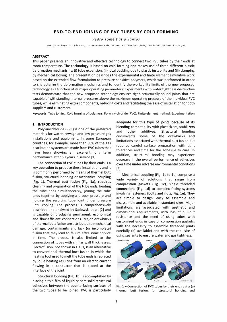
The connection of PVC tubes by their ends is a key operation to produce these installations and it is commonly performed by means of thermal butt fusion, structural bonding or mechanical coupling (Fig. 1). Thermal butt fusion (Fig. 1a), requires cleaning and preparation of the tube ends, heating the tube ends simultaneously, joining the tube ends together by applying a proper pressure and holding the resulting tube joint under pressure until cooling. The process is comprehensively described and analysed by Sadowski et al. [2] and is capable of producing permanent, economical and flow-efficient connections. Major drawbacks of thermal butt fusion are attributed to mechanical damage, contaminants and lack (or incomplete) fusion that may lead to failure after some service in time. The process is also limited to the connection of tubes with similar wall thicknesses. Electrofusion, not shown in Fig. 1, is an alternative to conventional thermal butt fusion in which the heating tool used to melt the tube ends is replaced by Joule heating resulting from an electric current flowing in a conductor that is placed at the interface of the joint.
Structural bonding (Fig. 1b) is accomplished by placing a thin film of liquid or semisolid structural adhesives between the counterfacing surfaces of the two tubes to be joined. PVC is particularly
adequate for this type of joints because of its blending compatibility with plasticizers, stabilizers and other additives. Structural bonding circumvents some of the drawbacks and limitations associated with thermal butt fusion but requires careful surface preparation with tight tolerances and time for the adhesive to cure. In addition, structural bonding may experience decrease in the overall performance of adhesives over time under adverse environmental conditions [3].
Mechanical coupling (Fig. 1c to 1e) comprise a wide variety of solutions that range from compression gaskets (Fig. 1c), single threaded connections (Fig. 1d) to complex fitting systems involving fasteners (bolts and nuts, Fig. 1e). They are simple to design, easy to assemble and disassemble and available in standard sizes. Major limitations are associated with aesthetic and dimensional requirements, with loss of pull-out resistance and the need of using tubes with customized ends in case of compression gaskets, with the necessity to assemble threaded joints carefully (if, available) and with the requisite of using sealants to ensure water and gas tightness.
Fig. 1 – Connection of PVC tubes by their ends using (a) thermal butt fusion, (b) structural bonding and

2
mechanical couplings based on (c) single threaded connections and (d) complex fitting systems.
From what was mentioned before, it is straightforward to conclude that ideal end-to-end joining of PVC tubes should ensure tight, structurally sound connections that are secure against leaking while eliminating unnecessary components, reducing costs and facilitating the ease of installation for both suppliers and customers.
This paper is aimed at contributing to this objective by proposing a new joining process that is capable of connecting two PVC tubes by their ends by means of a simple, effective and environmental friendly solution. The process employs axisymmetric plastic instability waves produced by cold forming of PVC tubes to create a mechanical lock between the tube ends and requires no additional components, adhesives or heating systems.
Cold forming of polymers has always been considered a niche positioned away from conventional polymer processing techniques based on heating-shaping-cooling manufacturing routes that are closely linked to mass production. The fundamentals of the cold forming of polymers have been comprehensively investigated since the mid 1960’s when Whitney and Andrews [4] proposed a pressure-modified Tresca yield criterion that gives rise to different yield strengths in tension and compression (a phenomenon known as the ‘strength-differential effect’). They observed, after measuring the changes in volume
of several polymers, that there is negligible volume variation after yielding and concluded that the normality rule, typical of associated plasticity, does not hold in case of pressure dependent yield surfaces.
The above conclusion was later confirmed by Raghava and Caddell [5] who assumed the principle of volume incompressibility to determine the thickness strains from experimental measurements of longitudinal and circumferential strains during pressure-bulge of thin-walled high density polyethylene tubes, and also by Spitzig and Richmond [6] who showed that the associated flow rule of a pressure-sensitive yield surface leads to predictions of volume variation at least one order of magnitude larger than those observed in the cold forming of polymers.
Under these circumstances, the aims and scope of this paper are to propose and evaluate a new joining process that is capable of connecting two PVC tubes by their ends. The presentation is supported by experimentation and finite element simulation using the aforementioned extension of the flow formulation to pressure-sensitive polymers that was recently developed by the authors [12]. Besides proposing a new joining process, the paper is also aimed at (i) providing understanding to its deformation mechanics, (ii) characterizing its modes of deformation and establishing the feasibility window as a function of the major operating parameters and (iii) assessing its overall performance by means of water tightness destructive tests.
2. EXPERIMENTATION 2.1. Mechanical characterization of the material
The investigation was performed on commercial PVC-U PN10 (Unplasticized Polyvinylchloride also known as Rigid Polyvinylchloride) tubes with an outer radius 𝑟𝑜 =16 mm and a wall thickness 𝑡𝑜 = 1.6 mm, in the ‘as-supplied’ condition. The tubes were manufactured in compliance with EN 1452-2 standard of the European Committee for Standardization and their maximum operating pressure is 10 bar. The choice of PVC-U (hereafter designated simply as ‘PVC’) was chosen because of its widespread application in water and sewage installations and equipment.
The strength-differential effect of PVC requires stress-strain curves to be obtained by means of tensile and stack compression tests. The tensile test specimens were machined from the supplied sheets in accordance to the ASTM D 638 standards. The stack compression test specimens consisted of
multi-layer cylinders that were assembled by pilling up 3 circular discs with 12 mm diameter and 1.6 mm thickness cut from the aforementioned PVC tubes by a hole-saw. Both tests were carried out at room temperature on a hydraulic testing machine (Instron SATEC 1200 kN) with a cross-head speed equal to 10 mm/min and the resulting evolutions of the true stresses with the true strains are plotted in Fig. 2a.
The critical instability load for the occurrence of axisymmetric local buckling was determined by compressing tubular specimens with 100 mm initial length between flat parallel platens (Fig. 2b). Two types of constraints with boundary conditions denoted as ‘free-ended’ and ‘fixed-ended’ were considered. In case of free-ended boundary conditions, both end surfaces of the tubes were neither laterally supported nor otherwise constrained whereas in case of fixed-ended boundary conditions both tube ends were fixed, so that there could be neither lateral displacement nor change in slope at either end. The

3
experimental load-displacement curves that were obtained for each constraint condition are similar.
Under these circumstances and assuming that the constraint conditions of the new proposed joining process are neither free-ended nor fixed-ended, the average critical instability load 𝐹𝑐𝑟 was estimated to be approximately equal to 11.3 kN (refer to the dashed black line in Fig. 2b).
(a)
(b)
Fig. 2 – Mechanical characterization of the PVC tubes: (a) True stress–true strain curves obtained from tensile and stack compression tests (the rightmost dashed region of the stress-strain curve obtained from tensile tests is extrapolated for finite element implementation); (b) Load-displacement curves obtained from the axial compression of tube specimens between two flat parallel platens.
2.2. New proposed process for joining PVC tubes The new proposed process for joining PVC
tubes by their ends is schematically shown in Fig. 3. As seen from the open, intermediate and closed positions of the tooling system, joining is accomplished by a sequence of three different cold forming stages that are carried out sequentially in a single stroke: (i) expansion, (ii) local buckling and (iii) clamping by mechanical locking.
Expansion is performed by forcing the upper tube against the chamfered end of the lower tube in order to enlarge the unsupported height 𝑙𝑜 of the upper tube radially and to create adjacent counterfacing surfaces between the two tubes to be joined. During this stage the chamfered end of
the lower tube acts like a tapered punch (refer to ‘first stage’ in Fig. 3b).
Once the unsupported height 𝑙𝑜 of the upper tube reaches the lower edge of the depth of insertion 𝑙𝑖𝑛𝑠 resulting from the radial clearance between the tube and the upper end of the lower die, there is a sudden change in material flow and plastic instability waves are triggered as a result of local buckling under axial compression loading (refer to ‘second stage’ in Fig. 3b). The internal mandrel ensures that the plastic instability waves are formed exclusively outwardly so that design specifications of the inner diameter of the tube joint are met and alterations in the flow of liquids or gases are prevented.
Finally, propagation of the plastic instability waves under continuous axial compression loading clamps the adjacent counterfacing surfaces of the two tubes by mechanical locking (refer to ‘third stage’ in Fig. 3b). Fig. 4 shows a photograph of the main active tool components of the upper and lower tubular preforms and of two tubes connected by their ends by means of the new proposed joining process, (right side) A process variant and (left side) B process variant.
It is worth noting that although the new proposed joining process has been developed for PVC tubes it can also be use in tubes made from other thermoplastics such as Polyethylene (PE) and Polypropylene (PP).
(a)

4
(b)
Fig. 3 – The new proposed process for the end-to-end joining of PVC tubes by cold forming with notation that is utilized throughout the paper: (a) Schematic representation of the tube joint A process variant; (b) Schematic representation of the tube joint B process variant.
Fig. 4 – Photograph of two tubes connected by their ends by means of the new proposed joining process (right side) A process variant and (left side) B process variant, included are the main active tool components of the upper and lower tubular preforms for B process variant.
2.3. Work plan, methods and procedures The experimental setup that is schematically
shown in Fig. 3 was installed in the hydraulic testing machine (Instron SATEC 1200 kN) where the mechanical characterization of the tube material had previously been performed. All the joining tests were carried out at room temperature with a cross head speed equal to that utilized in the mechanical characterization tests (10 mm/min).
Preliminary try-out tests carried out in the early stages of process development allowed identifying the major operating parameters of the joining process as: (i) the initial unsupported height 𝑙𝑜 of the upper tube, (ii) the initial unsupported height 𝑙𝑖 of the lower tube, (iii) the initial gap opening 𝑙𝑔𝑎𝑝 = 𝑙𝑜 + 𝑙𝑖 between the upper and lower dies,
(iv) the angle 𝛼 of the chamfered tube ends and (v) the axial compression load 𝐹𝑐𝑙𝑎𝑚𝑝 to clamp the
tubes by mechanical locking. The upper and lower dies were designed to a specific outer radius 𝑟𝑜 of the tubes and the mandrel was also dedicated to a specific wall thickness 𝑡𝑜 of the tubes to be joined. The ratio 𝑙𝑜/𝑙𝑖 of the initial unsupported height of the upper and lower tubes (also known as ‘the aspect ratio’) was kept constant and equal to 1 in all test cases.
The experimental work plan was split into two different parts. The first set of tests is summarized in Table 3 and was focused on the slenderness ratio 𝑙𝑔𝑎𝑝/𝑟𝑜 between the initial gap opening and the
outer radius 𝑟𝑜 of the tubes and on the angle 𝛼 of the chamfered tube ends. The axial compression load 𝐹𝑐𝑙𝑎𝑚𝑝 to clamp the tubes was kept equal to
30 kN in all these tests.
The second set of tests is summarized in Table 1 and was focused on the influence of the axial compression load 𝐹𝑐𝑙𝑎𝑚𝑝 on the morphology and
performance of the tube joints. The tests were built upon variations of the operating conditions of case 3 of Table 3 (refer to the grey cells in Table 3) and the destructive tests were carried out by increasing the water pressure inside the tube joint by means of two pistons up to a level of pressure at which leakage occurs. A schematic drawing is included in Table 2. The results of the tests included in Tables 1 and 2 are given later in the presentation.
Case 𝑙𝑜
(mm) 𝑙𝑖
(mm)
𝑙𝑔𝑎𝑝
(mm) 𝛼 (°)
𝑙𝑖𝑛𝑠 (mm)
1 10 10 20
20
5
2 15 15 30
3 20 20 40
4 25 25 50
5 30 30 60
6 20 20 40 40
7 20 20 40 60
8 20 20 40 90
9 10 10 20
20 0 10 15 15 30
11 20 20 40
12 25 25 50 Table 3 – The experimental work plan for investigating the influence of the slenderness ratio and of the angle of the chamfered tube ends on the performance of the tube joints (nomenclature according to Fig. 3.
Case 𝑙𝑔𝑎𝑝
(mm)
𝛼 (°)
𝐹𝑐𝑙𝑎𝑚𝑝
(kN)
Water tightness destructive test
A
40 20
15
B 30
C 40
D 80
E 200
F 30 Table 4 – The experimental work plan for investigating the influence of the axial compression load on the morphology and tightness of the tube joints (nomenclature according to Fig. 3.

5
3. NUMERICAL MODELLING The numerical modelling of the end-to-end joining
of PVC tubes by cold forming was performed with the in-house finite element computer program I-form that includes the extension of the flow formulation to pressure-sensitive polymers that was recently developed by the authors [12]. The extension of the flow formulation to pressure-sensitive polymers employs the pressure-modified version of the von Mises yield function ijF that explicitly accounts
for the differences between the compressive C and
tensile T flow stresses [7, 8],
0)(
2
kkTC
TCijF
(3.1)
where ijij 23 is the effective stress and
ijijkk . In case CT , the traditional von
Mises criterion (currently utilized in metals) results.
The strain rate-stress constitutive equations employed by this formulation are derived from a non-associated flow-rule in which the plastic potential Q
is not the yield function ijF in equation (3.1)
because of the experimental findings of Spitzig and Richmond [6] and Raghava and Caddell [5] regarding volume variation and incompressibility during the cold forming of polymers. Instead, the extended finite element flow formulation makes use of a plastic
potential Q retrieved from the classical 2J von-
Mises plasticity,
ij
ijpij
Q
(3.2)
where is a positive scalar factor of proportionality
and 2JQ .
The utilization of non-associated flow rules to achieve plastic incompressibility is not exclusive of the extended finite element flow formulation because other researchers followed a similar approach with other formulations. Stoughton and Yoon [16], for example, used an elasto-plastic formulation built upon a non-associated flow rule to simulate the material flow of aluminium alloys 2008-T4 and 2090-T3.
The extended finite element flow formulation included in the in-house computer program I-form is built upon the following variational statement,
dSdudSuT
dVKdV
f
r
T S
u
rfi
S
i
V
v
V
||
0
2
21
(3.3)
where, K is a large positive constant enforcing the
incompressibility constraint and V is the control
volume limited by the surfaces US and TS , where
velocity and traction are prescribed, respectively. Friction at the contact interface
fS between tubes
and tooling is assumed to be a traction boundary condition and the additional power consumption term is modelled through the utilization of the law of constant friction mkf . The finite element models
utilized throughout the investigation were planned in accordance to the experimental work plan of Tables 1 and 2 in order to reproduce all the experimentally observed modes of deformation. On account of rotational symmetry and because no anisotropy effects were taken into account, the models were accomplished by discretizing only the cross section of the initial PVC tubular preforms by means of axisymmetric quadrilateral elements. The contours of the dies were approximated by means of contact-friction linear elements. Several test runs with varying arrangements of quadrilateral elements in the thickness direction showed that the utilization of four elements was adequate for modelling the contact between the counterfacing surfaces of the two tubes and for obtaining a proper prediction of the load-displacement curve. The numerical modelling was accomplished through a succession of displacement increments each of one modelling approximately 0.01% of the initial tube length. The overall CPU time for a typical analysis consisting of a mesh with approximately 1100 nodal points and 900 linear quadrilateral elements was below 30 min on a standard laptop computer equipped with an Intel i7 CPU (2.7 GHz) processor.
Fig. 5 – Finite element modelling of the end-to-end joining of PVC tubes by cold forming: (left) Initial model with schematic representation of the contact between the counterfacing surfaces of the two tubes; (right) Intermediate and final deformation stages of case 3 of Table 3. The enclosed details show contact between the counterfacing surfaces of the two tubes in the regions where plastic flow is more significant. RESULTS AND DISCUSSION
3.1. Modes of deformation Similarly to what Alves et al. [17] recently found in
metallic tubes, the end-to-end joining of PVC tubes by cold forming is dependent upon the development and

6
propagation of sound axisymmetric plastic waves at the gap opening 𝑙𝑔𝑎𝑝 between the upper and lower
dies. Fig. 5a shows a photograph of the experimental PVC samples resulting from cases 1 to 5 of Table 3 and allow identifying three different modes of deformation that are dependent on the values of the slenderness ratio 𝑙𝑔𝑎𝑝/𝑟𝑜.
In fact, when the slenderness ratio 𝑙𝑔𝑎𝑝/𝑟𝑜 has a
value smaller than the minimum threshold like, for example, the leftmost sample of Fig. 5a where 𝑙𝑔𝑎𝑝/𝑟𝑜 = 0.56, it is not possible to connect the two
PVC tubes because the initial gap opening 𝑙𝑔𝑎𝑝 is not
big enough to allow plastic instability waves to develop and clamp the tubes by mechanical locking . The experimental and finite element predicted cross sections corresponding to case 1 that are shown in Fig. 5b help visualizing and understanding the reasons behind the absence of locking between the two PVC tubes.
In contrast, when the slenderness ratio 𝑙𝑔𝑎𝑝/𝑟𝑜 has
a value larger than the maximum threshold like, for example, the rightmost sample in Fig. 5a where 𝑙𝑔𝑎𝑝/𝑟𝑜 = 3.75, it is not possible to ensure a sound and
reliable connection of the PVC tubes by their ends. There are two reasons justifying the existence of a maximum threshold value 𝑙𝑔𝑎𝑝/𝑟𝑜 for the process
window. Firstly, when the slenderness ratio 𝑙𝑔𝑎𝑝/𝑟𝑜 is
very large, two or more plastic instability waves will form and interfere with each other during propagation and final clamping. Secondly, when the slenderness ratio 𝑙𝑔𝑎𝑝/𝑟𝑜 has a value larger than the maximum
threshold but not large enough to develop and propagate two or more plastic instability waves, there is a high possibility that these plastic instability waves will be triggered at the upper or lowed halves of the initial gap opening 𝑙𝑔𝑎𝑝 and lead to a poor quality
connection. Please refer to the experimental and finite element predicted cross sections corresponding to test case 5 in Fig. 5b.
Values of the slenderness ratio 𝑙𝑔𝑎𝑝/𝑟𝑜 in-between
the leftmost (case 1) and rightmost (case 5) samples in Fig. 5a are acceptable for connecting the two PVC tubes by their ends by means of cold forming. The process window is therefore restricted to values of the slenderness ratio 𝑙𝑔𝑎𝑝/𝑟𝑜 in the range between 1.8 and
3.2, which corresponds to cases 2 to 4 of Table 3.
(a)
(b)
Fig. 6 – Modes of deformation associated to end-to-end joining B of PVC tubes by cold forming: (a) Experimental results obtained from cases 1 to 5 of Table 3; (b) Experimental and finite element predicted cross sections of the joints corresponding to cases 1, 3 and 5 of Table 3; The enclosed shaded contour corresponds to the predicted distribution of crazing according to the normalized version stress-bias criterion.
(a)
(b)
Fig. 7 – Modes of deformation associated to end-to-end joining A of PVC tubes by cold forming: (a) Experimental results obtained from cases 9 to 12 of Table 3; (b) Experimental and finite element predicted cross sections of the joints corresponding to cases 9 and 12 of Table 3. The enclosed shaded contour corresponds to the predicted distribution of crazing according to the normalized version stress-bias criterion.
The observation of the modes of deformation and formability limits in the end-to-end joining of PVC

7
tubes by their ends add a new physical phenomenon known as ‘stress whitening’ that does not occur in the cold forming of metallic tubes. Stress whitening consists in the change of color with plastic deformation and is attributed to the occurrence of crazing in the regions of the tubes experiencing high values of tensile stresses. Fig. 5b includes the finite element predicted distribution of crazing in accordance with the normalized version of Bucknall's modification of the stress-bias criterion due to Sternstein and Ongchin [18],
2
0
11 RR
(3.4)
In the above equation 02 R and 0 is the
critical flow stress at the onset of crazing. In the
present work YT 0 , where YT is the yield
stress obtained from the experimental tensile tests.
As seen in Fig. 5b, the normalized version of Bucknall's stress-bias criterion takes values
101 in the outer fibers of the tube joints
subjected to tension in close agreement with the changes in color that are observed in these regions of the test samples. The remaining regions of the tubes that kept their original colour are subjected to values of 101 because they experience smaller
values of tensile stresses or compressive states of stress. Load-displacement evolution
Fig. 6 presents the experimental and finite element predicted evolution of the load with displacement for case 3 of Table 3. Three different regions are identified in good agreement with the three different forming stages of the new proposed end-to-end joining
process. Expansion of the unsupported height 0l of the
upper tube against the chamfered end of the lower tube (the first forming stage labelled as ‘A’ in Fig. 6) is characterized by an increase of the forming load up to a plateau that is typical of steady-state material flow conditions. During this stage the chamfered end of the lower tube acts like a tapered punch. Local buckling (the second forming stage labelled as ‘B’ in Fig. 6) starts simultaneously in both PVC tubes immediately
after the unsupported height 0l of the upper tube
reaches the lower edge of the depth of insertion 𝑙𝑖𝑛𝑠. The corresponding load-displacement evolution is characterized by a steep increase of the required forming load up to a peak value of approximately 23 kN, which is approximately twice the average critical instability load 𝐹𝑐𝑟 of a single PVC tube subjected to axial compression loading (refer to the dashed black line in Fig. 2b). After reaching the peak value there is a sudden drop of the load-displacement curve because the average critical instability load 𝐹𝑐𝑟 is a bifurcation point after which the total energy required by local buckling is smaller than the total energy required to
pursuit homogeneous deformation of the PVC tubes under axial compression.
The final upward tail of the load-displacement curve grows steeply from a lowered level to the axial compression load 𝐹𝑐𝑙𝑎𝑚𝑝 = 30 kN that was utilized to
clamp the two PVC tubes by mechanical locking (refer to the third forming stage labelled as ‘C’ in Fig. 6). The overall agreement between the experimental and the finite element predicted evolutions of the load with displacement is good.
Fig. 8 – Experimental and finite element predicted evolution of the load-displacement curves for case 3 of Table 3.
Observation of the experimental evolutions of the load with displacement for the test cases 1 to 5 of Table 3 that are depicted in Fig. 10 allows confirming that case 1 does not experience a bifurcation point in the required load because the initial gap opening 𝑙𝑔𝑎𝑝
is not big enough to allow plastic instability waves to develop. This further confirms the absence of locking between the two tubes in case 1.
The increase in the amount of displacement between the peak load corresponding to the onset of local buckling and the axial compression load to clamp the two PVC tubes with the largest slenderness ratio 𝑙𝑔𝑎𝑝/𝑟𝑜 also justifies the reason why multiple plastic
instability waves or simply poor quality connections may develop above the upper threshold limit 𝑙𝑔𝑎𝑝/
𝑟𝑜 ≥ 3.2.
Fig. 9 – Experimental evolution of the load-displacement curves for cases 1 to 5 of Table 3.

8
Fig. 10 – Experimental evolution of the load-displacement curves for cases 1 to 5 of Table 3.
3.2. Angle of the chamfered edges Fig. 11 discloses the influence of the chamfered
angle 𝛼 of the tube ends in the load-displacement curve. As seen, the increase of the chamfered angle 𝛼 from 20 to 60 degrees corresponding to cases 3, 6 and 7 of Table 3 does not compromise the overall success of the joining process but simply influences the peak load and the evolution of the load-displacement curve at the early instants of the joining process (the expansion stage). However, when the chamfered angle 𝛼 reaches 90 degrees it is not possible to connect the two PVC tubes because material flow changes from expansion against a tapered punch into axial compression of PVC tubes between flat parallel platens that was previously analysed in Fig. 2b.
(a)
(b)
Fig. 11 – End-to-end joining of tubes by plastic instability using different inclinations of the chamfered tube edges: (a) Experimental evolution of the load-displacement curves for cases 3, 6, 7 and 8 of Table 3; (b) Photographs of successful
and unsuccessful joints corresponding to test cases 3 and 8 of Table 3.
3.3. Morphology and tightness of the joints The influence of the clamping load 𝐹𝑐𝑙𝑎𝑚𝑝 on the
morphology and performance of the tube joints is shown in Fig. 12. The investigation was performed with the process operation conditions that are summarized in Table 5 and allowed concluding that the increase of 𝐹𝑐𝑙𝑎𝑚𝑝 gives rise to a decrease of the
overall height of the mechanical self-lock (Fig. 12a). In the extreme situation of test case E where 𝐹𝑐𝑙𝑎𝑚𝑝 =
200 kN, both tubes are subjected to a significant reduction of thickness in the joint as a result of radial expansion under positive hydrostatic stresses (refer to the detail included in Fig. 12b). This reduction in thickness justifies the reason why test case E experiences sudden collapse by fracture during water tightness tests, as shown in the rightmost photograph of Fig. 12c.
Fig. 12d presents the results of water tightness destructive tests for selected testing conditions corresponding to cases A and E of Table 6..
The tests were carried out by increasing the water pressure inside the tubes by means of two pistons (refer to the scheme in Table 7) up to a level of pressure at which leakage occurs. As seen in the figure, there is a first linear built-up of the water pressure with the displacement of the pistons for pressures below 13 bar in close agreement with the EN 1452-2 standard for the maximum operating pressure of the PVC tubes (10 bar). Then, the water pressure continues to built-up at a lower rate until reaching the amount of displacement of the pistons where the tube joint starts to deform (refer to region labelled as ‘J’). Further increase in the water pressure may lead to sudden collapse by failure and to pressurized water flowing out of the joint (e.g. case E – refer to the point labelled as ‘K’) or to failure along the tube wall as in case of conventional tube bulging (e.g. case A).
However, both results show that end-to-end joints are capable of withstanding water pressures well above the maximum operating pressure of 10 bar.

9
Fig. 12 – Influence of the axial compression load to clamp the PVC tubes on the overall morphology and performance of the end-to-end joints: (a) Photograph showing the changes in the morphology of the joints with the increase of the axial compression load to perform the clamp by mechanical self-locking (cases A to E of Table 8); (b) Finite element predicted distribution of hydrostatic stress (MPa) for case E of Table 9; (c) Photographic detail showing the initial and final geometries after finishing the water tightness tests of cases A and E of Table 10. A tube bulging test case is enclosed for reference purposes; (d) Experimental evolution of the pressure with the displacement of the pistons during water tightness tests of selected end-to-end joints. A tube bulging test case is enclosed for reference purposes.
4. CONCLUSIONS The new proposed technology for connecting two
PVC tubes by their ends by means of cold forming is an alternative to existing solutions based on thermal butt fusion, structural bonding and mechanical coupling. The joints are produced by plastic instability waves that are triggered simultaneously in both tubes to create a permanent mechanical lock that is capable of withstanding internal pressures well above the maximum operating pressure of the individual tubes.
Experimental and finite element simulations allow understanding the deformation mechanics of the process and characterizing the workability window as a function of the slenderness ratio 𝑙𝑔𝑎𝑝/𝑟𝑜 between
the initial gap opening 𝑙𝑔𝑎𝑝 and the outer radius 0r of
the tubes and of the angle 𝛼 of the chamfered tube ends.
Values of the slenderness ratio 𝑙𝑔𝑎𝑝/𝑟𝑜 in the range
between 1.8 and 3.2 gave rise to sound end-to-end tube joints. A wide range of angles of the chamfered
tube ends can be successfully employed because only values close 90º degrees will give rise to joining difficulties due changes in material flow from expansion against a tapered punch into axial compression between flat parallel platens during the early instants of the process.
The axial compression load 𝐹𝑐𝑙𝑎𝑚𝑝 to clamp the
tubes influences the morphology and tightness of the resulting tube joints. In particular, high values of 𝐹𝑐𝑙𝑎𝑚𝑝 are found to produce very thin joints and to
expose the periphery of the tubes to significant radial expansion under positive hydrostatic stresses, which lead to premature and sudden failure by leaking during the water tightness destructive tests.
Further research work is needed to explore the utilization of the new proposed technology to tubes made from other thermoplastic
ACKNOWLEGEMENTS The author would like to acknowledge all the support and precious guidance given by Professor Luís
Alves, Doctor Carlos Silva and Professor Paulo Martins.
REFERENCES [1] Hermkens R. Wolters M., Weller J., Visser R.: PVC
pipes in gas distribution: still going strong! Plastics Pipes Conference XIV, Budapest, Hungary (2008).
[2] Sadowski M.M., Murphy K.A.: Examination of current oil and gas industry practices for the evaluation of butt fusion welded high density polyethylene joints. NACE Northern Area Western Conference, Edmonton, Canada (2008).
[3] Gonçalves V.M., Martins P.A.F.: Joining stainless steel parts by means of weld bonding. International Journal of Mechanics and Materials
in Design, 3, 91–101 (2006). DOI 10.1007/s10999-006-9015-x
[4] Whitney W., Andrews R. D.: Yielding of glassy polymers: volume effects. Journal of Polymer Science - Part C, 16, 2981-2990 (1967). DOI: 10.1002/polc.5070160552
[5] Raghava R.S., Caddell R.M.: A macroscopic yield criterion for crystalline polymers. International Journal of Mechanical Sciences, 15, 967–974 (1973). DOI:10.1016/0020-7403(73)90106-9
[6] Spitzig W.A., Richmond O.: Effect of hydrostatic pressure on the deformation behaviour of polyethylene and polycarbonate in tension and in

10
compression. Polymer Engineering and Science, 19, 1129-1139 (1979). DOI: 10.1002/pen.760191602
[7] Raghava R.S, Caddell R.M., Yeh G.S.Y.: The macroscopic yield behaviour of polymers. Journal of Materials Science, 8, 225-232 (1973). DOI: 10.1007/BF00550671
[8] Caddell R.M., Raghava R.S., Atkins A.G.: Pressure dependent yield criteria for polymers, Materials Science and Engineering, 13, 113-120 (1974). DOI: 10.1016/0025-5416(74)90179-7
[9] Lee J.H.: Upper bound analysis of the upsetting of pressure-sensitive polymeric rings. International Journal of Mechanical Sciences, 30, 601–612 (1988). DOI: 10.1016/0020-7403(88)90102-6
[10] Lee J.H., Oung J.: Yield functions and flow rules for porous pressure-dependent strain-hardening polymeric materials, Journal Applied Mechanics - Transactions ASME, 67, 288-297 (2000). DOI:10.1115/1.1305278
[11] Alkas Yonan S., Silva M.B., Martins P.A.F., Tekkaya A.E.: Plastic flow and failure in single point incremental forming of PVC sheets. Express Polymer Letters, 8, 301-311 (2014). DOI: 10.3144/expresspolymlett.2014.34
[12] Alves L.M., Martins P.A.F.: Nosing of thin-walled PVC tubes into hollow spheres using a die. International Journal of Advanced Manufacturing Technology, 44, p 26-37 (2009). DOI:10.1007/s00170-008-1805-x
[13] Alves L.M., Martins P.A.F.: Cold heading of cylindrical PVC billets: experimental and
theoretical investigation. Journal of Materials Engineering and Performance, 19, 1276-1283 (2010).DOI: 10.1007/s11665-010-9633-1
[14] Zhu Y.X., Liu Y.L., Li H.P., Yang H.: Comparison between the effects of PVC mandrel and mandrel-cores die on the forming quality of bending rectangular H96 tube. International Journal of Mechanical Sciences, 76, 132–143 (2013). DOI: 10.1016/j.ijmecsci.2013.09.011
[15] Sanomura Y., Hayakawa K.: Modification of isotropic hardening model and application of kinematic hardening model to constitutive equation for plastic behaviour of hydrostatic-pressure-dependent polymers. Journal of the Society of Materials Science – Japan, 53, 143-149 (2004). DOI: 10.2472/jsms.53.143
[16] Stoughton T.B., Yoon J.-W.: A pressure-sensitive yield criterion under a non-associated flow rule for sheet metal forming. International Journal of Plasticity, 20, 705–731 (2004). DOI: 10.1016/S0749-6419(03)00079-2
[17] Alves L.M., Silva C.M.A., Martins P.A.F.: End-to-end joining of tubes by plastic instability. Journal of Materials Processing Technology, 214, 1954–1961 (2014). DOI: 10.1016/j.jmatprotec.2014.04.011
[18] Bucknall C.B.: New criterion for craze initiation. Polymer, 48, 1030-1041 (2007). doi: 10.1016/j.polymer.2006.12.033
[19] Sternstein S.S., Ongchin L.: Yield criteria for plastic deformation of glassy high polymers in general stress fields. Polymer Preprints - American Chemical Society, 10, 1117–1124 (1969).


![MODELING STRUCTURAL BEHAVIOUR OF PVC …confsys.encs.concordia.ca/ICCM19/AllPapers/FinalVersion/...absorption of circular CFRP tubes with diameter/thickness ratio [7] (b) Photograph](https://img.dokumen.tips/doc/110x75/5adb09867f8b9a6d318d8ddd/modeling-structural-behaviour-of-pvc-of-circular-cfrp-tubes-with-diameterthickness.jpg)


![Untitled-1 [rajendragroup.com] · As a market leader in the sector of C-PVC & I—I-PVC Pipe Fittings. ... made of and copper pipes. ... solvent-welded joining techniques,](https://img.dokumen.tips/doc/110x75/5ae7d5ce7f8b9a6d4f8eada0/untitled-1-a-market-leader-in-the-sector-of-c-pvc-ii-pvc-pipe-fittings-.jpg)


