Embed Size (px)
Citation preview
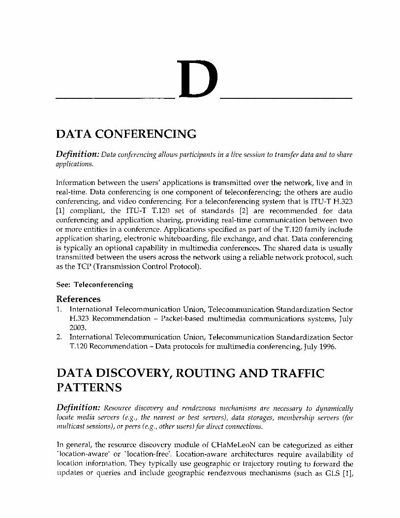
D DATA CONFERENCING
Definition: Data conferencing allows participants in a live session to transfer data and to share applications.
Information between the users' applications is transmitted over the network, live and in real-time. Data conferencing is one component of teleconferencing; the others are audio conferencing, and video conferencing. For a teleconferencing system that is ITU-T H.323 [1] compliant, the ITU-T T.120 set of standards [2] are recommended for data conferencing and application sharing, providing real-time communication between two or more entities in a conference. Applications specified as part of the T.120 family include application sharing, electronic whiteboarding, file exchange, and chat. Data conferencing is typically an optional capability in multimedia conferences. The shared data is usually transmitted between the users across the network using a reliable network protocol, such as the TCP (Transmission Control Protocol).
See: Teleconferencing
References 1. International Telecommunication Union, Telecommunication Standardization Sector
H.323 Recommendation - Packet-based multimedia communications systems, July 2003.
2. International Telecommunication Union, Telecommunication Standardization Sector T.120 Recommendation - Data protocols for multimedia conferencing, July 1996,
DATA DISCOVERY, ROUTING AND TRAFFIC PATTERNS
Definition: Resource discovery and rendezvous mechanisms are necessary to dynamically locate media servers (e.g., the nearest or best servers), data storages, membership servers (for multicast sessions), or peers (e.g., other users) for direct connections.
In general, the resource discovery module of CHaMeLeoN can be categorized as either 'location-aware' or "location-free". Location-aware architectures require availability of location information. They typically use geographic or trajectory routing to forward the updates or queries and include geographic rendezvous mechanisms (such as GLS [1],
140 D
Rendezvous Regions [2], and GHT [3]) and trajectory advertisement schemes (such as TBF [4]). In location-aware networks, geographic-based distributed hash tables [2, 3] are utilized to efficiently establish content based routing schemes.
In earlier work [2], we designed a geographic rendezvous mechanism based on rendezvous regions. In this architecture, the network is divided into regions, and the resource key space (e.g., file space) is divided into prefixes. Each resource prefixes maps into a region. The mapping can be discovered dynamically using a bootstrap mechanism. We have shown that using regions (instead of locations as in GHT [3]) is robust to mobility and location inaccuracy effects. Furthermore, the performance of the rendezvous architecture depends on the data semantics and access pattern. For example, for media servers, where there is a high lookup-to-insertion ratio (meaning the media is accessed many times per storage), the Rendezvous Regions scheme produces far fewer messages (over 80% less) when compared with GHT, and achieves near perfect success rate. Hence, it is important to tailor the rendezvous mechanism to the application characteristics (e.g., lookup-to-insertion ratio). Characterizing applications, data semantics and access patterns is of key interest. Matching rendezvous architectures to application classes, and designing new (adaptive) rendezvous mechanisms are additional challenges that need to be addressed in future work.
Location-free discovery architectures do not use location information [5]. Some of the main approaches include flooding-based techniques, on-demand routing with caching, hierarchical and hybrid routing. Flooding techniques include simple flooding (or expanding ring search), scoped flooding, and efficient reduced broadcast. Hierarchical routing includes cluster-based, landmark, and dominating set approaches. Hybrid routing includes zone routing and contact-based architectures. We have extensively studied these techniques. Our studies show that a loose hierarchy (using zones) coupled with 'contacts' achieves the best performance in terms of bandwidth and energy efficiency for the same success rates. The advantage of this scheme is most prominent for high-activity networks, where the query-to-mobility ratio is high since the cost of establishing and maintaining the hierarchy is amortized across savings in query cost. While route caching schemes are also useful in some scenarios, our studies have shown that the overhead of maintaining the cache up to date may outweigh its benefits for small transfers and high mobility show that for small transfers and high mobility caching validity may limit the efficacy of caching. Resource discovery may also be coupled with routing. For example, ZRP and the contact-based mechanisms are easily combined into one architecture, in which ZRP is used for route discovery while contact-based mechanisms are used for resource discovery (possibly over sub-optimal routes but with very high efficiency).
Routing Protocols In order to sustain data delivery with least disruption, routing protocols must adapt seamlessly to mobility [5]. Pure proactive approaches (e.g., DSDV) may incur high overhead and may not be able to cope with high mobility scenarios. On the other hand reactive protocols (e.g., DSR and AODV) incur much less overhead and are suitable for small/medium networks (<100 nodes), but also incur delivery disruption due to link failures and route maintenance. Hybrid protocols (e.g., ZRP) uses proactive routing
Encyclopedia of Multimedia 141
within for nearby nodes (within the zone) and reactive routing discovery for nodes beyond the zone. ZRP is suitable for larger networks (>100 nodes) but also suffers packet loss with link failures. We intend to investigate the use of reactive route discovery with proactive route maintenance in CHaMeLeoN. Such schemes are bandwidth efficient and able to proactively discover new routes before the existing ones break. This investigation borrows from existing work in this area in addition to designing new mechanisms.
Dynamic content, generated by real-time communications, will often be delivered to a group of participants in a session. The mode of communication depends on the definition of the 'group'. For dynamically created logical groups, multicast [6] may be used for efficient communication. For ad hoc networks, in general, mesh-based multicast routing is more robust to network dynamics than tree-based routing. This is at the expense of increased overhead. For geographically defined groups, geocast [7] may be used. For locating either any or nearest participant, anycast [6] may be used. Finally, manycast [8] may be used for locating k out of n participants. Hence, routing and transport protocols are needed to support such applications. Dynamics of the multicast group membership (whether in terms of senders/producers or receivers/consumers) would have a great impact on the performance of the various protocols and hence on the quality of data delivery. Dealing with dynamics of membership, traffic patterns, and mobility are issues we address in the routing and protocol design and evaluation phases of CHaMeLeoN.
Storage-Retrieval of Dynamic Content When dynamic content is to be stored for future retrieval, issues of dynamic storage, indexing, querying and retrieval must be addressed. Resource and data discovery architectures are needed to facilitate server (or file) location by the interested parties without having to flood the request throughout the network. Such storage-retrieval architecture should be self-configuring, scalable and robust to network dynamics (including mobility). They impact the data placement issues discussed previously.
In the design of the above protocols, including resource discovery and multicast protocols, modeling and analysis of user and information association are essential. Association analysis captures traffic and access patterns within groups of nodes. Associations and traffic patterns depend on the nature of the application. The network nodes can be either dedicated to users or can be autonomous (e.g., as in sensor networks). With CHaMeLeoN, we are interested in two types of associations: (a) small world friend associations in user-centric networks (such as wireless classrooms or collaboration using ad hoc networks), and (b) data correlation in data-centric sensor networks.
This analysis will facilitate the design of traffic prediction (and subsequently data placement) schemes to improve the performance and availability of data. In addition, mobility prediction schemes will facilitate seamless delivery of data. We shall address mobility based schemes in research in the following section.

142 D
Traffic Patterns and Information Associations CHaMeLeoN may utilize traditional address-centric (or user-centric) paradigms to associate devices with information. A data-centric approach may also be feasible and must be investigated further. We describe each in turn.
With a user-centric approach, users establish communities that manifest association of conversation, file sharing, trust, correlated mobility or common interests. We have been investigating these social behaviors and the concept of friends in wireless networks using the small world's models [9]. Small worlds refer to classes of graphs that exhibit high clustering similar to that of regular graphs, but a low average path length (i.e., degree of separation) similar to that of random graphs. Small world graphs have been observed in many contexts of human behavior, in security (PGP) associations, web links, and interest groups, among others. By understanding such social underpinnings, we shall develop a better and deeper understanding of correlated access patterns, mobility, security and other network associations. This will result in efficient networking protocols. Moreover, we aim to achieve desirable characteristics of small worlds by constructing carefully chosen short cuts to bridge the gap between otherwise distant clusters of users or information. One example of such structure is building a small world of trust to establish security associations efficiently in large-scale wireless networks. We shall focus on understanding information associations in wireless classrooms as one of our target applications.
Data-centric paradigms apply to sensor networks where the physical phenomena monitored produces data that is observed/recorded by multiple sensors. Hence sensor readings may be correlated. Sometimes the physical phenomenon propagates according to well-known diffusion laws, creating natural spatio-temporal gradients of information in the sensor network. This may relate to protocol design and in-network processing with CHaMeLeoN, e.g., using data aggregation or gradient based routing [10].
See: Data Management Techniques for Continuous Media in Ad-hoc Networks of Wireless Devices
References 1. J. Li, J. Jannotti, D. Couto, D. Karger, and R. Morris, "A Scalable Location Service for
Geographic Ad Hoc Routing (GLS/Grid)", Proceedings of the ACM MobiCom, 2000. 2. K. Seada and A. Helmy, "Rendezvous Regions: A Scalable Architecture for Service
Location and Data-Centric Storage in Large-Scale Wireless Networks," Proceedings of the IEEE/ACM IPDPS Int'l Workshop on Algorithms for Wireless, Mobile, Ad Hoc and Sensor Networks (WMAN), April 2004, pp. 218 - 225.
3. S. Ratnasamy, B. Karp, L. Yin, F. Yu, D. Estrin, R. Govindan, and S. Shenker, "GHT: A Geographic Hash Table for Data-Centric Storage," Proceedings of the ACM WSNA, September 2002.
4. D. Niculescu and B. Nath, "Trajectory-based forwarding and its applications," Proceedings of the ACM Mobicom, September 2003.
5. A. Helmy, "Efficient Resource Discovery in Wireless AdHoc Networks: Contacts Do Help," Book Chapter in "Resource Management in Wireless Networking,'' Springer,

Encyclopedia of Multimedia 143
Series: Network Theory and Applications, Vol. 16, 2005, (Eds. M. Cardei, I. Cardei, and D. Zhu).
6. A. Helmy, "Architectural Framework for Large-Scale Multicast in Mobile Ad Hoc Networks," Proceedings of the IEEE International Conference on Communications (ICC 2002), April, 2002.
7. K. Seada and A. Helmy, "Efficient and Robust Geocasting Protocols for Sensor Networks," Journal of Computer Communications - Elsevier, Special Issue on Dependable Wireless Sensor Networks, Fall 2005.
8. C. Carter, S. Yi, P. Ratanchandani, and R. Kravets, "Manycast: Exploring the Space Between Anycast and Multicast in Ad Hoc Networks," Proceedings of the ACM Mobicom, September 2003.
9. A. Helmy, "Small Worlds in Wireless Networks," IEEE Communications Letters, Vol. 7, No. 10, October 2003, pp. 490-492.
10. J. Faruque, K. Psounis, and A. Helmy, "Analysis of Gradient-based Routing Protocols in Sensor Networks," Proceedings of the IEEE/ACM Int. Conference on Distributed Computing in Sensor Systems (DCOSS), June 2005, pp. 258 - 275.
DATA ENCRYPTION STANDARD (DES) AND ADVANCED ENCRYPTION STANDARD (AES)
Definition: Data Encryption Standard (DES) and Advanced Encryption Standard (AES) are designed to encrypt a sequence of data elements.
The DES algorithm is designed to encipher and decipher 64-bit blocks of data under control of a 64-bit key, of which 56 bits are randomly generated and used directly by the algorithm. Deciphering must be accomplished by using the same key as for enciphering. The deciphering process is the reverse of the enciphering process. A 64-bit block to be enciphered is subject to an initial permutation to form LQ and RQ (32 bits each,
respectively the left and right half of the 64-bit block generated by the initial permutation), then to 16-iteration key-dependent computation, and the final result of the computation (Lj^ and R^^) is subject to a permutation that is the inverse of the initial permutation. The 16 key-dependent computations can be simply defined as [1]:
/?„=L,,_,e/(/?„_„/^j
where n is in the range of 1 to 16; / is the cipher function; L,, and /?,, are 32-bits each
and respectively the left and right half of the 64-bit iteration result; and K^^ is the 48-bit
sub key generated by the following key schedule function KS [1]:
K,^=KS{n,KEY)
where KEY is the 56-bit main key.

144 D
With the advance of computation power, a 56-bit key is no longer considered as secure. Triple DES (3DES) is a straightforward way of enhancing the security of DES. 3DES involves repeating the basic DES algorithm three times, using either two or thee unique keys, for a key size of 112 or 168 bits [1].
Both DES and 3DES are not efficient because they operate on a 64-bit block. As a replacement, the Advanced Encryption Standard (AES) specifies the Rijndael algorithm, a symmetric block cipher that can process data blocks of 128 bits, using cipher keys with lengths of 128,192, and 256 bits [2].
See: Multimedia Authentication
References 1. National Institute of Standards and Technology, ''Specification for the Data
Encryption Standard (DES)," Technical Report NIST PIPS PUB 46-3, Department of Commerce, October 1999.
2. National Institute of Standards and Technology, "Specification for the Advanced Encryption Standard (AES)," Technical Report NIST PIPS PUB 197, Department of Commerce, November 2001.
DATA MANAGEMENT TECHNIQUES FOR CONTINUOUS MEDIA IN AD-HOC NETWORKS OF WIRELESS DEVICES
Shahram Ghandeharizadeh, Ahmed Helnty, Bhaskar Krishnamachari, Francois Bar, and Todd Richmond University of Southern California^ Los Angeles, USA
Definition: This article introduces CHaMeLeoN as a large scale software effort to facilitate exchange of both traditional (text, image) and continuous media (audio and video clips).
CHaMeLeoN is designed to support both delayed and immediate modes of communication. It is targeted toward mobile devices configured with a heterogeneous mix of wired and wireless components. Our primary focus is on the limited radio-range of wireless connections (such as 802.11) and exchange of data among those devices that are in close geographical vicinity of one another to participate in an ad-hoc network. We outline the objectives of CHaMeLeoN, and in short articles summarize our research findings to date.
Introduction Rapid advances in wireless technology, computational, mass storage, and sensor devices are realizing new paradigms of communication in wireless mobile environments. They offer a compelling vision of the future Internet as a seamlessly integrated heterogeneous system. Continuous media (video and audio) services are of particular interest because

Encyclopedia of Multimedia 145
they are necessary for many classes of important and interesting applications, ranging from entertainment to scientific collaboration. These applications can be broadly categorized into those that manage content pertaining to either immediate, delayed, or both modes of communication. Delayed communication is when a user records and stores data in anticipation of its future retrieval, e.g., display of a recordings from a recent meeting or seminar. Immediate communication is when a user generates data for display at a client in real-time, e.g., scientists communicating and collaborating across different laboratories. The boundary between these two modes of communication is defined by the delay from when data is produced to the time it is displayed. As this delay increases, immediate mode of communication becomes delayed. A good example is when the collaborating scientists record their real-time communication for future display and analysis.
A number of visionary systems such as Memex [1] and MyLifeBits [4] depend on devices that capture and retrieve data pertaining to both communication modes. The computer and communication industry has started to develop such devices. For example, today's cellular phones facilitate phone conversations between multiple parties, capture photos and record videos of their surroundings, and transmit the recorded information to other cellular phones and devices with Internet Protocol (IP) connectivity. Similarly, cable set-top boxes, termed Digital Video Recorders (DVRs), support telephone conversations (Voice over IP, VoIP), provide time-shifted viewing of broadcasted programs, and store personal audio and still image libraries. (TiVo terms these additional features ^^home media" in its Series2 offerings.) It is not far fetched to envision DVR extensions to store personal video libraries along with meta-data associated with the different data items. It might be extended with either one or multiple wireless networking cards to facilitate (1) an in-home network for uploading of content from devices that capture data such as a camcorder, and (2) an ad-hoc network consisting of other DVRs in the neighboring households. Such a device can be implemented using today's wireless technology such as 802.11a/g which offers limited radio-range with bandwidths in the order of tens of Mbps [2]. We term such a device a Home-to-Home Online (H20) [6] device.
Current technological trends point towards multi-purpose Personal Digital Assistants (PDAs) that are small, inexpensive, weigh less than a pound, and have long lasting battery lives. To facilitate efficient retrieval of data, these PDAs might be equipped with sensors that capture a variety of metadata about their surroundings. An example sensor might be a global positioning system to record the geographical location of different recordings and communications [5]. This would enable a user to retrieve all those photos captured from a specific location, e.g., India. This PDA will communicate with diverse networks. For example, it might interface with a vehicle's multimedia network to enable a passenger to share his or her personal recordings with other passengers using the vehicle's fold-down screen. The same PDA will communicate with any H20 device for sharing of photos and video clips. Mobility of PDAs and their potential intermittent [11] network connectivity differentiates them from H20 devices.
This article provides an overview of the ChaMeLeoN framework and its design decisions. CHaMeLeoN is designed to support both delayed and immediate mode of communication in a wireless, heterogeneous network of multihop, mobile devices. This
146 D
framework touches upon a wide range of issues such as security and privacy [3], economic fairness, user interfaces, strategies to satisfy the requirements of diverse applications sharing the same infrastructure, and many others. A study of all topics in depth is beyond the scope of this paper. Instead, we focus on the core infrastructure of the network, namely, techniques to deliver continuous media in a manner that meets the application requirements and challenges of a mobile wireless environment.
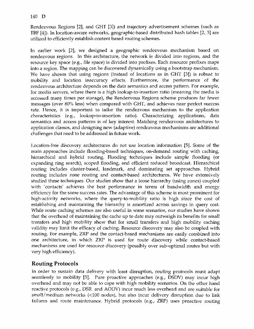
Overview of CHaMeLeoN A unique feature of CHaMeLeoN is its awareness of (and adaptation to) the application requirements and environmental constraints. These are shown as the top and bottom layers of Figure 1. CHaMeLeoN, the mid layer, consumes input from these two layers: First, communication mode of the application (immediate, delayed, or both) and its requirements (QoS, efficiency, and availability of data; see below for details). Second, environment and network characterization in the form of: (a) mobility models -including synthetic or trace based mobility models, (b) traffic patterns and information association (e.g., due to users' social behavior or correlation of sensed data), (c) constraints of limited power, computation or communication capabilities, and (d) model of the wireless channel. The core of the framework consists of parameterized adaptive algorithms and protocols for data placement, scheduling and merging, admission control, data and resource discovery, data delivery and routing protocols. In addition, protocol design for mobility is a component that may span multiple other core components to include mobility prediction, mobility-resilient and mobility-assisted protocols. For example, data placement may be based on mobility prediction, and resource discovery may be mobility-assisted.
Figure 1. The CHaMeLeoN Framework.
Encyclopedia of Multimedia 147
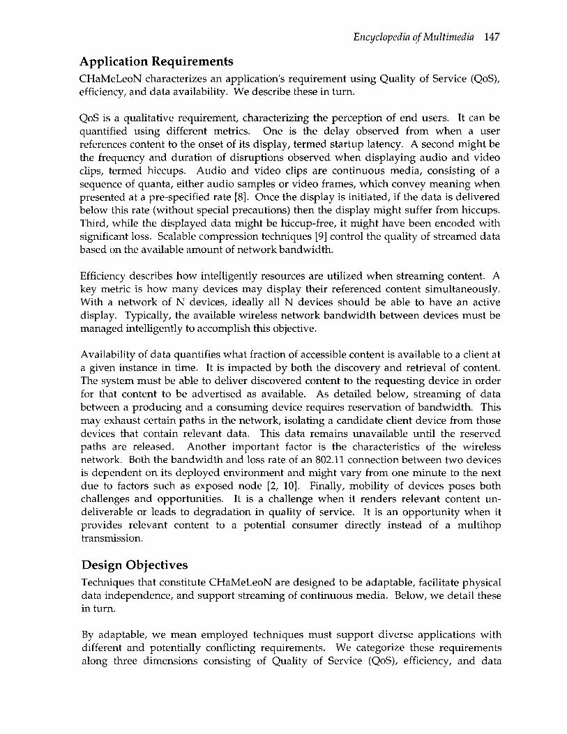
Application Requirements CHaMeLeoN characterizes an application's requirement using Quality of Service (QoS), efficiency, and data availability. We describe these in turn.
QoS is a qualitative requirement, characterizing the perception of end users. It can be quantified using different metrics. One is the delay observed from when a user references content to the onset of its display, termed startup latency. A second might be the frequency and duration of disruptions observed when displaying audio and video clips, termed hiccups. Audio and video clips are continuous media, consisting of a sequence of quanta, either audio samples or video frames, which convey meaning when presented at a pre-specified rate [8]. Once the display is initiated, if the data is delivered below this rate (without special precautions) then the display might suffer from hiccups. Third, while the displayed data might be hiccup-free, it might have been encoded with significant loss. Scalable compression techniques [9] control the quality of streamed data based on the available amount of network bandwidth.
Efficiency describes how intelligently resources are utilized when streaming content. A key metric is how many devices may display their referenced content simultaneously. With a network of N devices, ideally all N devices should be able to have an active display. Typically, the available wireless network bandwidth between devices must be managed intelligently to accomplish this objective.
Availability of data quantifies what fraction of accessible content is available to a client at a given instance in time. It is impacted by both the discovery and retrieval of content. The system must be able to deliver discovered content to the requesting device in order for that content to be advertised as available. As detailed below, streaming of data between a producing and a consuming device requires reservation of bandwidth. This may exhaust certain paths in the network, isolating a candidate client device from those devices that contain relevant data. This data remains unavailable until the reserved paths are released. Another important factor is the characteristics of the wireless network. Both the bandwidth and loss rate of an 802.11 connection between two devices is dependent on its deployed environment and might vary from one minute to the next due to factors such as exposed node [2, 10]. Finally, mobility of devices poses both challenges and opportunities. It is a challenge when it renders relevant content un-deliverable or leads to degradation in quality of service. It is an opportunity when it provides relevant content to a potential consumer directly instead of a multihop transmission.
Design Objectives Techniques that constitute CHaMeLeoN are designed to be adaptable, facilitate physical data independence, and support streaming of continuous media. Below, we detail these in turn.
By adaptable, we mean employed techniques must support diverse applications with different and potentially conflicting requirements. We categorize these requirements along three dimensions consisting of Quality of Service (QoS), efficiency, and data

148 D
availability; see below for details. One application may demand the highest QoS while another may emphasize availability of data and services. Proposed techniques are parameterized whose settings navigate the three dimensional optimization space. The challenge here is to identify the parameters of a technique, quantify how their settings navigate the optimization space, and design of algorithms to navigate this space given the physical realities of an environment.
Physical data independence means the organization of data can be modified without causing application programs to be rewritten. Physical organization of data might be manipulated either at its storage or delivery time. To illustrate, CHaMeLeoN must manage physical organization of clips when storing them. In certain environments, participating devices may collaborate by contributing some of their storage to a common pool in order to enhance QoS and efficiency metrics. With a video clip, the data placement component of CHaMeLeoN may aggressively replicate the first few blocks of a clip across many devices to enable a client to display the clip immediately while it discovers and retrieves the remaining blocks of the clip [7]. An application may not want to use this placement strategy because its participating devices are expected to be disconnected from the network for long durations of time. This should not mean that one re-writes the data placement component. Instead, either (a) this component's parameter settings must enable a system designer to deploy it in a manner that meets this application's requirement or (b) metadata associated with a clip provides sufficient context for the data placement strategy to meet this application's requirement. While both approaches realize physical data independence, the first is at system deployment time while the second is at run-time using meta-data provided either by an application or its clips. The challenge here is design, implementation, and testing of flexible software.
Streaming of continuous media facilitates overlapped display of a clip at a client with its delivery from a network of one or several servers. This is essential for immediate mode of communication because participants require real-time data exchange. Even with delayed mode of communication, streaming is useful because it minimizes the amount of time a user waits for the system to initiate display of a clip. To illustrate, a 30 minute DVD quality video is typically 900 Megabytes in size. If the system downloads the clip prior to initiating its display then the client must wait for the duration of time to download 900 Megabytes of data. Even if the network provides a bandwidth of 100 Megabits per second, the client must wait for more than a minute. With streaming, the display starts once sufficient data is prefetched at the client to hide the time required to deliver the remainder of a clip. A challenge here is how to determine the size of prefetch portion. This is a challenge because network bandwidth might fluctuate dramatically during delivery of a clip, causing one or more clients to starve for data. This causes the display to suffer from frequent disruptions and delays, termed hiccups. A related challenge is how to recover from these scenarios. The obvious solution is to free up bandwidth by terminating one or more clients. The key question is how to determine the identity of victim clients in a decentralized manner while respecting the application's overall requirements.
See: Placement of Continuous Media in Ad-Hoc Networks of Devices
Encyclopedia of Multimedia 149
References 1. V. Bush. "As We May Think," The Atlantic Monthly, Vol. 176, No. 1, July 1945, pp.
101-108. 2. S. Bararia, S. Ghandeharizadeh, and S. Kapadia, "Evaluation of 802.11a for Streaming
Data in Ad-hoc Networks," Proceedings of the Fourth Workshop on Applications and Services in Wireless Networks, August 2004.
3. W. Cheng, L. Golubchik, and D. Kay, "Total Recall: Are Privacy Changes Inevitable?" Proceedings of the First ACM Workshop on Continuous Archival and Retrieval of Personal Experiences, New York, NY, October 2004.
4. J. Gemmell, B. Gordon, R. Lueder, S. Drucker, and C. Wong. "MyLifeBits: Fulfilling the Memex Vision," ACM Multimedia, December 2002.
5. J. Gemmell, L. Williams, K. Wood, G. Bell, and R. Lueder, "Efficient Retrieval of Life Log Based on Context and Content," Proceedings of the First ACM Workshop on Continuous Archival and Retrieval of Personal Experiences, New York, NY, October 2004.
6. S. Ghandeharizadeh and T. Helmi, "An Evaluation of Alternative Continuous Media Replication Techniques in Wireless Peer-to-Peer Networks," In Proceedings of Third International ACM Workshop on Data Engineering for Wireless and Mobile Access (MobiDE, in conjunction with MobiCom'03), September 2003.
7. S. Ghandeharizadeh, B. Krishnamachari, and S. Song, "Placement of Continuous Media in Wireless Peer-to-Peer Networks," IEEE Transactions on Multimedia, April 2004.
8. S. Ghandeharizadeh and R. Muntz, "Design and Implementation of Scalable Continuous Media Servers," Parallel Computing, 24(1):91~122, May 1998.
9. R. Rejaie and A. Ortega, "PALS: Peer to Peer Adaptive Layered Streaming," Proceedings of NOSSDAV, June 2003.
10. D. Shukla, L. Chandran-Wadia, and S. Iyer, "Mitigating the Exposed Node Problem in IEEE 802.11 Ad Hoc Networks," Proceedings of IEEE International Conference on Computer and Communication Networks (ICCN), Oct 2003.
11. A. Spyropoulos, K. Psounis, and C. Raghavendra, "Spray and Wait: An Efficient Routing Scheme for Intermittently Connected Networks," Proceedings of the ACM SIGCOMM Workshop on Delay Tolerant Networking (WDTN-05), August 2005.
DATA MODELING, MULTIMEDIA
Simone Santini University of California, San Diego, USA and Universidad Autonoma de Madrid, Spain
Definition: Multimedia data modeling refers to creating the relationship between data in a multimedia application.
Data modeling {sans multimedia), mush like requirement engineering, is in a sense a hybrid discipline that operates as a bridge between, on one side, some branch of the computing profession and, on the other, the problems from other disciplines to which the

150 D
computing profession applies its solutions. In the general acceptance of the term, data modeling has the purpose of creating a formal data structure that captures as well as possible the (often informal) data of the application, and the relations between them. Standard data modeling is often done using semi-formal methods such as the entity-relationship diagrams [1]. These methods, in general, put the emphasis on the relationship between the data, rather than on the data themselves: the data are often represented as simple data types (integers, strings, etc.) connected by the relations of the model.
A greater emphasis on the data themselves is placed by so-called object-oriented approaches [2,3], most of which make use of graphic formats such as UML [4]. (Object oriented methods in general, and UML in particular, are designed as notations to specify the structure of programs and, as such, are not quite suitable for data modeling. To name but one problem, in UML design it is necessary to decide immediately which entities are objects and which are attributes, a decision that should properly be left to a later stage of the design process.) It is worth noticing that an object in the typical object oriented modeling formalism is not an object at all, since it is not a truly abstract data type, in that its internal structure is always explicit and part of the model: in this sense, an object in a data model is closer to Pascal's records or C structures than to objects.
Multimedia data are often complex and have a rich structure and, at least in their static aspects, are often modeled using object oriented modeling formalisms, possibly with a higher level of abstraction since the extreme complexity of certain multimedia structure pushes the designer to place the emphasis of a design on the behavior of multimedia data rather than on their structure. But, apart from some adjustment to allow a higher degree of abstraction, multimedia data would probably have little to add to the general area of data modeling were it not for the issue of time.
Many multimedia data have a time component, and the existence of this component creates issues, such as data flow or synchronization, that are quite alien to traditional modeling techniques. The timing problems of multimedia data are, in fact, quite independent of those of areas such as historical data bases, temporal queries, or real time data bases, vis a vis which data modeling has developed its time modeling techniques. Multimedia data are often retrieved and processed in order to be presented, and the technical or psychophysical differences in the perception of different types of data imposes, in the multimedia arena, considerations unknown in the case of other data modeling problems.
To make but an example, in a multimedia presentation the synchronization between the presentation material (typically: transparencies) and the audio-video content is relatively coarse—a mismatch of the order of seconds can be tolerated—while the synchronization between the audio and the video of the speaker must be considerably finer: a mismatch of a single frame (1/30 * sec.) is already noticeable. (The means to achieve synchronization also depend on the characteristics of the medium and of its perception: video frames, for example, can be dropped more readily than audio packets, as the human sensory system discerns gaps in audio as more prominent and disruptive than comparative gaps in video; this kind of problems, however, belong to a level different than that of data modeling, and will not be considered here.)

Encyclopedia of Multimedia 151
Many of these problems are solved by suitable querying, access, or indexing techniques. The purpose of data modeling is, for multimedia as for other types of data, to provide a suitably formalized view of the relevant data structures, so that a suitable solution can be designed. In the specific area of multimedia, next to the traditional aspects of data modeling, this entails the specification of the temporal relations between the data, as a prolegomenon, e.g., to the temporal schema design of the data bases involved in a system.
An important representation often used in multimedia data modeling is that of intervals (in time) [5]. Given a set of instants T, a partial order on T, and two elements
a,bET with a<b,the interval [a,b] is the set {t\tET,a<t<b}. Note that, contrary to the common intuition, time is represented here as a partially ordered set. This stipulation is useful, e.g. for modeling situations of time uncertainty when, given two events e, ^62, at instants ^,,^2' *^^ uncertainty in the measurement of time doesn't allow one to determine which of the two events came first.
Many multimedia modeling problems have to do with synchronization, that is, with the temporal relation between pieces of multimedia data, each one considered as an interval. The simplest case of such relation is that between two intervals, in which case there are 13 topologically distinct relations in which they can be, represented, using the graphical notation of Allen [6] by the seven relations in Figure 1 and by the inverses of the first six (the inverse of the seventh is clearly equal to the relation itself).
Here, D , D (resp. D , Bb) are the start time and duration of event a (resp. b), i'h their
relative position {Tg = yl^ ~^aV ^^^ ^^ *^^ duration of the composition of intervals.
The relations between intervals can be expressed in terms of conditions on these parameters. For instance:
abeforeb = (;r„+r„<;rJ
and so on. Binary relations can be extended to lists of intervals by assuming that each pair of contiguous intervals stands in the same binary relation. In this case, for instance, the n-meets relation would be represented as
/; h h
Several partial order relations can be defined for intervals. Intervals being sets, the most obvious one is probably the set inclusion relation which, in terms of the time parameters of the intervals, translates to

152 D
but this order doesn't capture the temporal semantics, so to speak, of the interval relation: one would like, at least, a partial order that, in the limit when the length of the intervals tends to zero, becomes isomorphic to the total order of time instants (without uncertainty).
%
\
^
<—
^a
a
^ >
1 h
>
-F
^ '^b ^ f
b
—>
n,.
a before b
\^
<— T^5 ^
^ - ^
b 1
—>
K, TZu
a l b
< ^ >'
< >
a meets b
^b
f
> ^
f a
a
:w
^ ^
b ^ ^ ^ ^
^ > ^
V ^
a overlaps b a i contained in b
: . ^ „
< >
''I
^ ^ ^ r'
« ^ >F
a ^ ^
' ^ "W >F
b 1
^ ^' ^ >
> ^ >
T^a
a fi^-
'w ^
^ ^ ^ ^
^ ^
f- —> b 1
v' >
a ^rarr^ b
: ,
a equals b
di finishes b
« ^ ^ T
.
a
^ >
1 ^ >
fe V >
b 1
V " 1 ^ ^
Figure 1. Temporal relations between pieces of multimedia.

Encyclopedia of Multimedia 153
A partial ordering such as
would do the job. This partial ordering is related somewhat to the qualitative interval relations since, for instance,
a before b^> a<b
a meets b=> a<b
and so on.
Unrestricted intervals generate unrestricted partial orders, that is, by creating— somewhat artificially—an initial and a final events, every lattice corresponds to a feasible set of temporal intervals. This modeling formalism is therefore very expressive, but it also creates considerable problems in the translation of the model into a data base schema or an algorithm. For instance, not only do some query expressions yield a result exponential in the size of the input but, given a query expression e, whether there is an
input p such that e(p) is exponential in \p\ is undecidable [7].
Models of reduced expressivity have been proposed. For example, if intervals are used only to model time uncertainty, and such uncertainty can be bounded, then one can use a model in which all intervals have the same length (namely, the bound on the uncertainty). In this case, it can be shown that the resulting lattice will not contain any sub-lattice isomorphic to the following lattices:
A V
The partial order is then a semiorder, for which more efficient algorithms are available [8]. An important, if often imprecise, notion in multimedia modeling is that of stream. The intuitive notion here is that, although multimedia presentations are, perforce, finite in time, in many applications one hasn't got access to the whole presentation instantaneously: since processing typically takes place while the presentation is being displayed, at any time only the data up to the time of presentation—or shortly thereafter, if the presentation can be buffered and displayed with a certain delay—are available for processing. Even if buffering is permissible, so that data up to a certain time in the future are available, it is in general unfeasible, both on timing and on storage grounds, to buffer

154 D
the whole presentation and process it as a whole. Rather, it is assumed that at time t the
processing algorithm only has access to data in a suitable time window [t — t^,t].
Because the processing is, so to speak, oblivious of the boundaries of the presentation, it is often convenient to model the presentation itself as an infinite set.
More formally, given a set M of media types (any form of data representing the possible instantaneous values of a given medium), and the lattice I of intervals, a (discrete) stream is a pair of functions U'.N -^ M , V. N -^ I such that TT^ (v{i)) < n^ {v(i +1)) for all
/. The number i identifies a sample in the stream, v(i) defines the temporal placement of that sample, and u(i) its contents in terms of data. At time t, only the values of the function such that 71^ (^(0) " ^ ^^^ computable.
Many applications of multimedia, towards which these models are oriented, involve either the synchronization of streams (which, at the level of data modeling, is specified using the interval relations seen above) or some form of stream query, not dissimilar to what is done in temporal data bases [9]. In these cases, typically, a feature extraction function is applied to the data function u to yield one or more feature streams, on which the query can be executed.
References 1. C. Batini, S. Ceri, S. B. Navathe, and S. Navathe, "Conceptual Database Design: An
Entity-Relationship Approach," Reading: Addison Wesley, 1991. 2. W. Klas, E. J. Neuhold, and M. Schrefl, "Using an object-oriented approach to model
multimedia data," Computer Communications, Vol. 3, No. 4, pp. 204—16,1990. 3. D. Woelk, W, Kim, W. Luther, "An object-oriented approach to multimedia
databases," Proceedings of the ACM-SIGMOD 1986 Conference on Management of Data, pp. 311—25,1986.
4. A. Dennis, B. H. Wixom, and D. Tegarden, "Systems Analysis and Design : An Object-Oriented Approach with UML", Wiley, 2001.
5. T.D.C. Little and A. Ghafoor, "Interval-based conceptual models for time-dependent multimedia data," IEEE Transactions on Knowledge and Data Engineering, Vol. 5, No. 4, pp. 551—63, August 1993.
6. J. F. Allen, "Maintaining knowledge about temporal intervals," Communications of the ACM, Vol. 26, No. 11, pp. 832—43, November 1983.
7. S. Grumbach and T. Milo, "An algebra for pomsets," Proceedings of the International Conference on Database Theory, pp. 191—207, Heidelberg:Springer-Verlag, 1995.
8. S. Bhonsle, A. Gupta, S. Santini, M. Worring, and R. Jain, "Complex visual activity recognition using a temporally ordered database," Proceedings of Visual 99: International conference on Visual Information Management Systems, Amsterdam, June 1999.
9. O. Etzion, S. Jajodia, and S. Sripada (Eds.), "Temporal databases: research and practice," Heidelberg:Springer-Verlag, 1998.

Encyclopedia of Multimedia 155
DEAD RECKONING
Definition: Dead reckoning is commonly used to compensate for packet losses and delays in online gaming.
With the aim of providing users with high levels of interactivity in the course of frenetic fast paced games, a large number of latency hiding techniques have been devised that aim at compensating transmission delays and packet losses. In essence, much of the focus on improving real-time interactions within online multi-player game sessions is on how to reduce response times experienced by players. For timely game state updates at player consoles, dead reckoning is commonly used to compensate for packet losses and delays. In this specific context, prominent works are those presented in [1, 2, 3].
In particular, dead reckoning schemes typically aim at predicting the actual positions of moving entities during the game evolution. These schemes are based on the idea of updating entities' trajectories rather than static positions. Thus, for each entity, the position estimation is calculated based on previous moves of the entity.
Different schemes are possible for the prediction of a future event or position. As an example, the most common approach is that of considering entities moving at a constant speed. In this case, the position of a moving entity is predicted by resorting to a first order equation: x(ti) = xo + v(ti - to), where tt and to represent, respectively, the actual local time and the time of the last received event, while x(ti), xo and v are vectors in a 2D or 3D space. In particular, v represents the constant speed that identifies also the trajectory of the moving entity, and xo represents the known position of the entity at time to. It is clear that such an approach may be fully exploited to predict the position of moving entities provided that events and correlated movements may be described based on a first order equation. Otherwise, alternative prediction schemes may be exploited such as, for example, second order equations. These assume that entities move with a constant acceleration i.e., x(ti) = Xo + v(ti - to) + Vi a(ti - tg)^. Finally, different prediction schemes could include methods that exploit constant speed circular motion [1].
It is quite obvious that these dead reckoning schemes work well for game entities that perform simple (and slow) trajectories such as, for example, tank movements in a (game) military simulation. However, the problem of dead reckoning is that moves may be incorrectly predicted, especially in case of (fast moving) complex trajectories. In this case, in fact, inconsistencies may occur. In such situation, dead reckoning schemes must be devised that adopt control techniques that allow identifying possible inconsistencies between the predicted entity's position and the actual real position of the entity.
Finally, due to the fact that dead reckoning algorithms typically encode continuous move actions within game events, it results that synchronized clocks and game event timestamps must be exploited to process such game events at their exact points in time. In fact, network latencies could introduce inaccuracies in the entities trajectories if game events would be roughly processed as soon as they are received without any control on their specific time of generation.

156 D
See: Online Gaming
References 1. S. Aggarwal, H. Banavar, A. Khandelwal, S. Mukherjee, and S. Rangarajan,
"Accuracy in dead-reckoning based distributed multi-player games," Proceedings of ACM SIGCOMM 2004 Workshop on NetGames '04: Network and System Support for Games, Portland, Oregon, USA, pp. 161-165, 2004.
2. K. Alex and S. Taylor, "Using determinism to improve the accuracy of dead reckoning algorithms," Proceedings of Simulation Technologies and Training Conference, Sydney, 2000.
3. L. Pantel and L.C Wolf, "On the suitability of dead reckoning schemes for games," Proceedings of the 1 ^ Workshop on Network and System Support for Games, pp. 79-84, ACM Press, 2002.
DEMOSAICKED IMAGE POSTPROCESSING
Definition: Demosaicked image postprocessing is used after a demosaicking module in a processing pipeline to enhance the quality of demosaicked, full-color, camera images.
The most essential step in a single-sensor imaging pipeline is the demosaicking process. However, demosaicking solutions usually introduce visual impairments, such as blurred edges and color shifts. Therefore, demosaicked image postprocessing should be used after a demosaicking module in a processing pipeline to enhance the quality of demosaicked, full-color, camera images (Figure 1) [l]-[3].
demosaicked (full-color) image
demosaicked image postprocessing
enhanced color image
Figure 1. Demonstration of a demosaicked image postprocessing/enhancement concept.
Unlike demosaicking, which is considered a stand-alone procedure, demosaicked image postprocessing is an optional step which complements (without replacing) the available demosaicking solutions [2],[3]. It performs full color image enhancement (Figure 2), as the input to the postprocessor is a demosaicked, full-color, Red-Green-Blue (RGB) image and the output is an enhanced RGB color image. Since the CFA image values are not affected by the demosaicking step and thus, they are included in a demosaicked output image, the postprocessing process should improve the color appearance and sharpness, as well as eliminate false colors by utilizing the information from both its demosaicked components and the original CFA data. The objective can be achieved by employing, in a fully automated manner, both an edge-sensing mechanism and a spectral model to track the varying spatial and spectral characteristics of the demosaicked image.
Such enhancement operations can be treated as either a postprocessing procedure incorporated as the last step in a demosaicking pipeline or as an independent

Encyclopedia of Multimedia 157
postprocessing operation. Unlike demosaicking, postprocessing can be applied iteratively until certain quality criteria are met [3]. The postprocessor can be implemented either in hardware or software on the camera itself. Alternatively, the postprocessing of the demosaicked image can be performed in a personal computer using software distributed by the camera manufacturer or by utilizing conventional, public image processing tools. Thus, the proposed postprocessing concept can complement the existing CFA based processing pipelines [l]-[3].
(a) (b)
Figure 2. Visually contrasted: (a) demosaicked image obtained using a cost-effective processing solution, and (b) postprocessed demosaicked image with an enhanced visual
quality.
See: Digital camera image processing, Demosaicking, Spectral model. Edge-sensing mechanism. Color image filtering and enhancement.
References 1. R. Lukac, K. Martin, and K.-N. Plataniotis, "Color-Difference Based Demosaicked Image
Postprocessing," lEE Electronics Letters, Vol. 39, No. 25, December 2003, pp. 1805-1806. 2. R. Lukac, K. Martin, and K.-N. Plataniotis, "Demosaicked Image Postprocessing
Using Local Colour Ratios," IEEE Transactions on Circuits and Systems for Video Technology, Vol. 14, No. 6, June 2004, pp. 914-920.
3. R. Lukac and K.-N. Plataniotis, "A Robust, Cost-Effective Postprocessor for Enhancing Demosaicked Camera Images," Real-Time Imaging, Special Issue on Spectral Imaging II, Vol. 11, No. 2, April 2005, pp. 139-150.
DEMOSAICKING
Definition: Demosaicking is the process of recovering the color information in the systems, which use only a single image sensor.
Cost-effective consumer electronic devices use only a single image sensor to capture the visual scene. The monochromatic nature of the sensor necessitates covering its surface by a color filter array (CFA) which is used to capture all the three, Red-Green-Blue (RGB) primary colors at the same time. Since the single-sensor allows only one color to be measured at each spatial location, the acquired CFA image data constitute a mosaic-like gray-scale image. To recover the color information (Figure 1), the two missing color
158 D
components must be determined from the adjacent pixels. This estimation process is commonly termed demosaicking, but it is also known as CFA interpolation or color interpolation [l]-[3].
gray-scale CFA mosaic-like image
demosaicking demosaicked full-color image
Figure 1. Demonstration of a demosaicking concept.
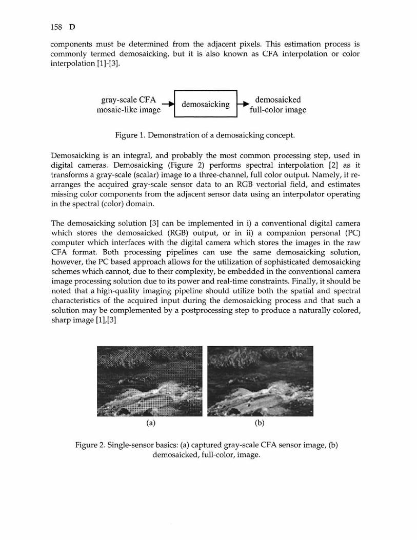
Demosaicking is an integral, and probably the most common processing step, used in digital cameras. Demosaicking (Figure 2) performs spectral interpolation [2] as it transforms a gray-scale (scalar) image to a three-channel, full color output. Namely, it re-arranges the acquired gray-scale sensor data to an RGB vectorial field, and estimates missing color components from the adjacent sensor data using an interpolator operating in the spectral (color) domain.
The demosaicking solution [3] can be implemented in i) a conventional digital camera which stores the demosaicked (RGB) output, or in ii) a companion personal (PC) computer which interfaces with the digital camera which stores the images in the raw CFA format. Both processing pipelines can use the same demosaicking solution, however, the PC based approach allows for the utilization of sophisticated demosaicking schemes which cannot, due to their complexity, be embedded in the conventional camera image processing solution due to its power and real-time constraints. Finally, it should be noted that a high-quality imaging pipeline should utilize both the spatial and spectral characteristics of the acquired input during the demosaicking process and that such a solution may be complemented by a postprocessing step to produce a naturally colored, sharp image [1],[3]
Figure 2. Single-sensor basics: (a) captured gray-scale CFA sensor image, (b) demosaicked, full-color, image.
Encyclopedia of Multimedia 159
See: Digital camera image processing. Spectral model. Edge-sensing mechanism, CFA image zooming, Demosaicked image postprocessing. Color image zooming. Color image filtering and enhancement.
References 1. R. Lukac, K.-N. Plataniotis, D. Hatzinakos, and M. Aleksic, ''A Novel Cost Effective
Demosaicing Approach," IEEE Trans. Consumer Electronics, Vol. 50, No. 1, February 2004, pp. 256-261.
2. R. Lukac, B. Smolka, K. Martin, K.-N. Plataniotis, and A.-N. Venetsanopulos, "Vector Filtering for Color Imaging," IEEE Signal Processing Magazine; Special Issue on Color Image Processing, Vol. 22, No. 1, January 2005, pp. 74-86.
3. R. Lukac and K.-N. Plataniotis, "Data-Adaptive Filters for Demosaicking: A Framework," IEEE Transactions of Consumer Electronics, submitted for publication.
DESKTOP VIRTUAL REALITY
Definition: Desktop virtual reality uses a computer monitor for virtual reality applications.
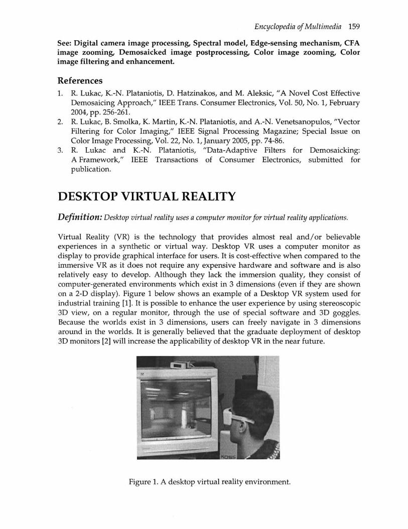
Virtual Reality (VR) is the technology that provides almost real and/or believable experiences in a synthetic or virtual way. Desktop VR uses a computer monitor as display to provide graphical interface for users. It is cost-effective when compared to the immersive VR as it does not require any expensive hardware and software and is also relatively easy to develop. Although they lack the immersion quality, they consist of computer-generated environments which exist in 3 dimensions (even if they are shown on a 2-D display). Figure 1 below shows an example of a Desktop VR system used for industrial training [1]. It is possible to enhance the user experience by using stereoscopic 3D view, on a regular monitor, through the use of special software and 3D goggles. Because the worlds exist in 3 dimensions, users can freely navigate in 3 dimensions around in the worlds. It is generally believed that the graduate deployment of desktop 3D monitors [2] will increase the applicability of desktop VR in the near future.
Figure 1. A desktop virtual reality environment.

160 D
See: Virtual and Augmented Reality
References 1. J.C. Oliveira, S. Shirmohammadi, M. Cordea, E. Petriu, D. Petriu, and N.D.
Georganas, "Virtual Theater for Industrial Training: A Collaborative Virtual Environment," Proceedings of the 4th World Multiconference on Circuits, Systems, Communications and Computers (CSCC 2000), Athens, Greece, July 2000, Vol. IV, pp. 294-299.
2. A. Sullivan, "3-Deep," IEEE Spectrum, Vol. 42, No. 4, 2005, pp. 22-27.
DEVICE-DRIVEN PRESENTATION OF MULTIMEDIA CONTENT
Definition: Device-driven presentation of multimedia content deals with the issue how can multimedia content be made available to end users considering the devices, display characteristics, processing capabilities, and connectivity.
For some time the only way to access and work with digital content was the personal computer or workstation. Not only is the volume of digital content (including text, pictures, audio, video, or other niultimedia content) growing, but in particular the variety of devices that are available for presentation of digital content. Thus there is the need to deliver content that is adapted to the different characteristics and capabilities, i.e., delivery context, of the devices. Delivery context as described in [1] is "a. set of attributes that characterizes the capabilities of the access mechanism, the preferences of the user and other aspects of the context into which a web page is to be delivered." Generalizing this definition for any kind of presentation, the main question to be addressed is: how can multimedia content be made available to end users considering the devices, display characteristics, processing capabilities, and connectivity. There are mainly three solutions to this problem: 1) composition of different documents dedicated for presentation on different devices; 2) provision of single media elements and system-driven dynamic selection and merging of these elements into a coherent document/presentation adapted to the delivery context; or 3) use of a highly flexible document model that supports the presentation of the digital content on different devices.
Considering the wide variety of different capabilities and different characteristics of devices composing a separate document for each class of devices is just unacceptable. Provisioning single media elements and developing algorithms that select and merge them into a single document relevant to the delivery context is the first real opportunity to provide context-driven presentation of multimedia content. Projects of this kind are very often single media centered (e.g., delivering text or photos) but there are some novel research approaches aiming at the development of a generic modular framework, e.g. [2, 3] that supports the composition of personalized (i.e., context sensitive) multimedia presentations for multiple devices. The third approach - using a flexible document model that allows to create content once and use it everywhere - has attracted significant research interest: e.g., W3C specifications of document models aiming at support for

Encyclopedia of Multimedia 161
different devices are SVG Mobile (a model that brings the 2D vector graphics to the mobile web using two profiles: SVG Tiny, suitable for highly restricted devices, and SVG Basic for higher level mobile devices), SMIL 2.1 Mobile Profile (provides support for SMIL presentation within the context of a mobile device), or (X)HTML, which is very often supported by mobile devices as well. The advantages of using the latter type of models are, among others, the easy content development and maintenance using popular authoring tools and well- established support by different devices. Very often the document models are XML-based, which allows XML-based processing techniques. A major drawback of this approach is the resulting complexity for the author since manual authoring of such documents adaptable to different delivery contexts is not feasible without appropriate (WYSIWYG) authoring tools.
See: Context-Aware Multimedia
References 1. W3C, "Delivery Context Overview for Device Independence," W3C Working Group
Note, January 2005. 2. A. Scherp and S. Boll, "Generic support for personalized mobile multimedia tourist
applications," Proceedings of the 12th Annual ACM International Conference on Multimedia, New York, 2004, pp. 178-179.
3. K. Nahrstedt and W. Balke, "A taxonomy for multimedia service composition," Proceedings of the 12th Annual ACM International Conference on Multimedia, New York, 2004, pp. 88-95.
DIAMOND SEARCH FOR BLOCK MOTION ESTIMATION
Definition: Diamond search technique for block motion estimation is based on diamond search patterns.
The process of block matching motion estimation is to find out a candidate block, within a search area in the previous frame, which is most similar to the current block in the present frame. To speed up the search process, a number of fast search algorithms have been developed in the past two decades. It is shown that the diamond search (DS) algorithm [1] [2] can achieve a better compromise between the complexity and prediction performance among different methods.
Diamond search makes use of the center-biased motion characteristics of video sequences and uses diamond search patterns (Figure 1) instead of rectangular as most of other search methods. It also uses the halfway stop criterion to allow early termination of the search. The detailed steps of DS are shown below. Figure 2 shows an example how DS locates the motion vector.

162 D
Step 1 The initial large diamond search pattern is centered at the search origin, the (0,0) position, and nine search location are checked. If the minimum MAD point is located at the center, go to Step 3; otherwise, go to Step 2.
Step 2 Use the minimum MAD point found in the previous step as the center of the large diamond search pattern. Calculate the MAD values for those new search points in the search pattern. If the minimum MAD point is located at the center, go to Step 3; otherwise, recursively repeat this step.
Step 3 Use the small diamond search pattern. Four more search points are checked. The minimum MAD point found in this step is the final solution of the motion vector which points to the best matching block.
-7
(a) Large Diamond Search Pattern 0
+7
(b) Small Diamond Search Pattern
Figure 1. Search patterns.
See: Motion Compensation for Video Compression
i
\
i f
h
%
i
9 i
\ ^
4 k
/K 1
^
y
^ 5 r
\N}
*4
s L
s
^' (/
"1 '"J J
? '-1
J
t J
^
i ft
-7 0 +7 rigure z. example or uiamona i^earcn.
References. 1. J. Y. Tham, S. Ranganath, M. Ranganath, and A. A. Kassim, "A novel unrestricted
center-biased diamond search algorithm for block motion estimation," IEEE Transactions of Circuits and Systems for Video Technology, Vol. 8, pp. 369-377, August 1998.
2. S. Zhu and K. K. Ma, "A new diamond search algorithm for fast block matching motion estimation," IEEE Transactions of Image Processing, Vol. 9, pp. 287-290, February 2000.

Encyclopedia of Multimedia 163
DIGITAL BIOMETRICS
Forouzan Golshani Department of Computer Science & Engineering Wright State University, Dayton, OH, USA
Definition: Digital biometrics refers to measurements on -physiological or behavioral characteristics of a person for determining or verifying the identity of a person.
Biometrics deals with the science of identification (or verification) of a person based on some physiological, behavioral, or genetic characteristics. Digital biometrics refers to measurements on physiological or behavioral characteristics of a person, generally obtained through automated technological means, for determining or verifying the identity of a person. Physiological biometrics is the data gathered from direct measurement of the human body, obtained by means of various procedures and algorithms that can uniquely identify the individual. Examples include: fingerprint, hand geometry, iris, retinal, vein, voice, and facial imaging. Behavioral biometrics, however, is measured by analyzing a specific set of actions of a person. These may include how a person talks, signs their name, walks, writes, or types on a keyboard. Work in the field of multimedia directly contributes to computational biometrics, both physiological and behavioral. Face recognition techniques and retina scan analysis are examples of contributions to the physiological biometrics. Gait analysis, where the person recognized by their activities, for instance manner of walking, is an example of where multimedia techniques play a crucial role.
From another perspective, biometric technologies can be categorized into active and passive techniques. Active biometrics include: fingerprint, hand geometry, retina scanning, and signature recognition technologies. Examples of passive biometrics procedures are: voice recognition, iris recognition, and facial recognition. The first two are somewhat limited but the last, facial imaging, can be truly passive.
Biometric technologies are becoming the foundation of a large number of highly secure identification and human verification solutions. In the identification mode (one to many), the biometric system compares the given individual to all individuals in the database and ranks the top possible matches. In a verification mode (one to one), the system compares the given individual with who that individual says they are and provides a yes/no answer. Identification is generally associated with surveillance, whereas a clear application of verification is access control.
The need for biometrics-based systems can be found in the government sector (federal, state and local), the military, and commercial applications. Many enterprise-wide network security infrastructures are already benefiting immensely from multimedia-based biometric technologies, including secure electronic banking and other financial transactions, retail sales, law enforcement, and government IDs. Biometric-based authentication applications include access control for workstation, network, and domain, data protection, application logon, and remote access to resources.

164 D
The performance of a monomodal biometric system depends greatly on the ability of the sensor to capture data and also on the features of the biometric trait captured. Any irregularity in the capture phase reflects on the performance metrics of the system and might greatly increase the error rates. There are several issues regarding the biometrics being used. Not all of the biometric traits (physiological or behavioral) are universal or unique-enough. Some are variant with time (aging), cannot be quantified well, are not acceptable by all people (intrusive), can be faked to fool the system, and some are not robust enough. Noisy data also creates a variance in matching correctly. The success of any biometric verification system relies on the properties of the trait on which the system is based. Usually these peculiarities result in compromised success.
Incorporating multiple biometric traits for authentication can alleviate most of these problems. Multimodal systems are expected to be more reliable and that is due to the fact that multiple sensors are used to catch different biometric traits. The system thus has multiple pieces of evidence of identity (or lack of it). These systems can be configured to match levels of security based on application. Due to the requirement of several biometrics, it will be difficult for intruders to fake all traits and violate the integrity of the system. Information fusion, i.e., how to integrate the information received from individual modalities, is the key to success of these systems. We will review several techniques used in various systems.
Computational Biometrics Some common sources of biometrics data are: fingerprints, face images, voice patterns, retinal or iris scanning, hand geometry, signatures, key strokes, gait features, and 3D scans. These have the common characteristics of being identifiers that are intrinsically associated with the individual in question, can be reproduced anytime, and cannot easily be lost or stolen.
Fingerprints: This is the oldest and best known biometric parameter for identification and authentication. Each finger on a person's hand has a unique pattern which can distinguish the person from all other members of the universe. Formed in the embryonic stages of life, the ridges and their flows and patterns do not change over time, other than enlargement due to the natural growth of the body over time. Because of their use in forensics and a number of other applications, fingerprints have been studied more extensively over much longer period of time as compared to other biometrics.
Digital fingerprints are obtained by means of a variety of sensors in the form of an electronic image, to which a series of image enhancement algorithms are applied to remove undesirable artifacts and to improve contrast. Next, local ridge orientations are estimated, followed by local thresholding. The next step, feature extraction from fingerprints leads to extraction of minutiae. A variety of features (up to 50 or more) are extracted from ridges such as ridge bifurcations, patterns created by ridge flow characteristics, highest point of the innermost ridge, and delta points separating pattern areas and non-pattern areas. The feature set, collectively, defines the minutia. Steps leading to minutia extraction are: Calculation of flow orientations; Localization of pattern areas; Extraction of ridges; Thinning of the ridges, and Minutia representation. A
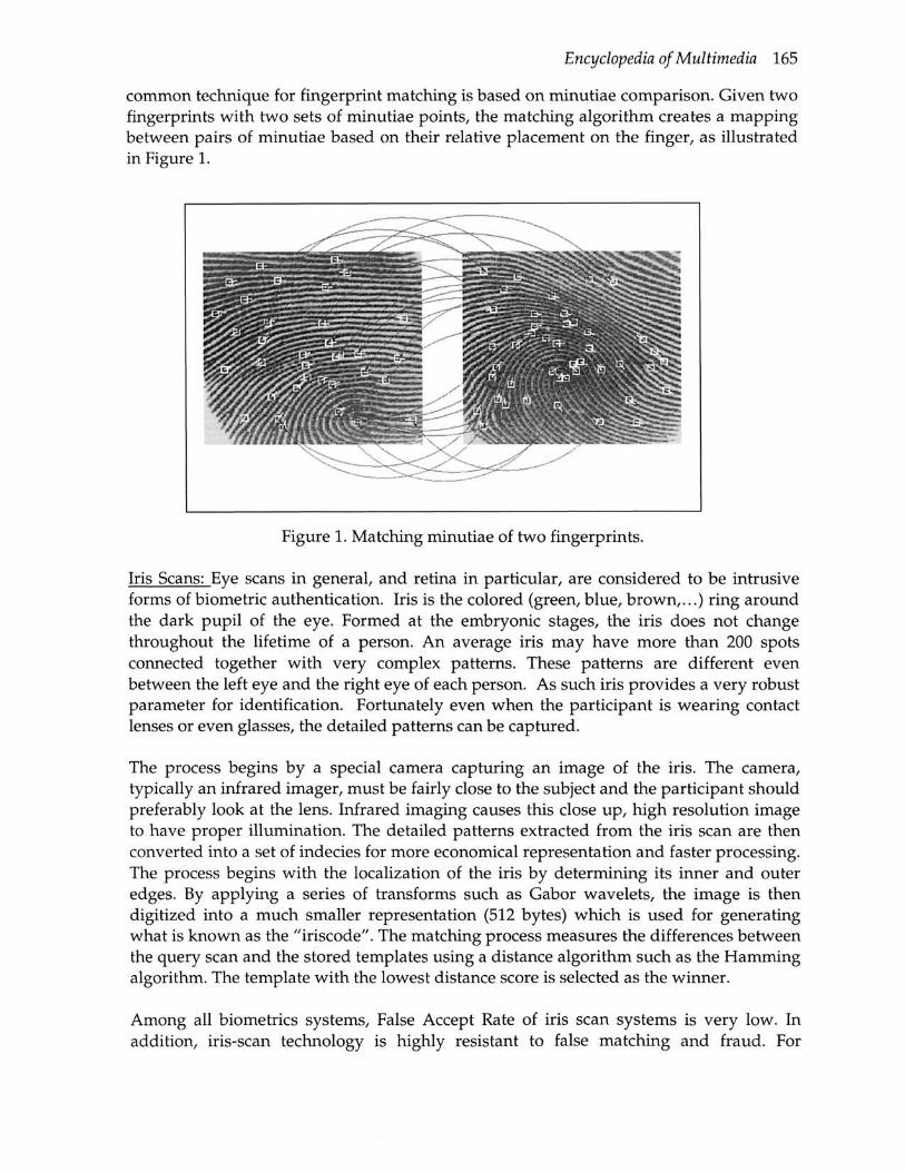
Encyclopedia of Multimedia 165
common technique for fingerprint matching is based on minutiae comparison. Given two fingerprints with two sets of minutiae points, the matching algorithm creates a mapping between pairs of minutiae based on their relative placement on the finger, as illustrated in Figure 1.
Figure 1. Matching minutiae of two fingerprints.
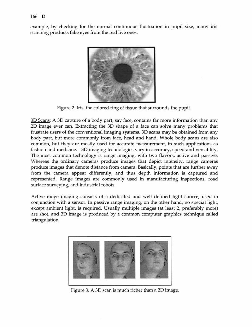
Iris Scans: Eye scans in general, and retina in particular, are considered to be intrusive forms of biometric authentication. Iris is the colored (green, blue, brown,...) ring around the dark pupil of the eye. Formed at the embryonic stages, the iris does not change throughout the lifetime of a person. An average iris may have more than 200 spots connected together with very complex patterns. These patterns are different even between the left eye and the right eye of each person. As such iris provides a very robust parameter for identification. Fortunately even when the participant is wearing contact lenses or even glasses, the detailed patterns can be captured.
The process begins by a special camera capturing an image of the iris. The camera, typically an infrared imager, must be fairly close to the subject and the participant should preferably look at the lens. Infrared imaging causes this close up, high resolution image to have proper illumination. The detailed patterns extracted from the iris scan are then converted into a set of indecies for more economical representation and faster processing. The process begins with the localization of the iris by determining its inner and outer edges. By applying a series of transforms such as Gabor wavelets, the image is then digitized into a much smaller representation (512 bytes) which is used for generating what is known as the "iriscode". The matching process measures the differences between the query scan and the stored templates using a distance algorithm such as the Hamming algorithm. The template with the lowest distance score is selected as the winner.
Among all biometrics systems. False Accept Rate of iris scan systems is very low. In addition, iris-scan technology is highly resistant to false matching and fraud. For
166 D
example, by checking for the normal continuous fluctuation in pupil size, many iris scanning products fake eyes from the real live ones.
Figure 2. Iris: the colored ring of tissue that surrounds the pupil.
3D Scans: A 3D capture of a body part, say face, contains far more information than any 2D image ever can. Extracting the 3D shape of a face can solve many problems that frustrate users of the conventional imaging systems. 3D scans may be obtained from any body part, but more commonly from face, head and hand. Whole body scans are also common, but they are mostly used for accurate measurement, in such applications as fashion and medicine. 3D imaging technologies vary in accuracy, speed and versatility. The most common technology is range imaging, with two flavors, active and passive. Whereas the ordinary cameras produce images that depict intensity, range cameras produce images that denote distance from camera. Basically, points that are further away from the camera appear differently, and thus depth information is captured and represented. Range images are commonly used in manufacturing inspections, road surface surveying, and industrial robots.
Active range imaging consists of a dedicated and well defined light source, used in conjunction with a sensor. In passive range imaging, on the other hand, no special light, except ambient light, is required. Usually multiple images (at least 2, preferably more) are shot, and 3D image is produced by a comnnon computer graphics technique called triangulation.
Figure 3. A 3D scan is much richer than a 2D image.

Encyclopedia of Multimedia 167
Capturing, processing, and matching 3D images involve the following major steps: triangulation, generation of pointcloud data, application of transforms such as 3D wavelets, generation of polygon and polygon sets, feature analyses for extraction of 3D feature sets, indexing and classification of features, surfaces and surface orientations, topology of objects, production of facial component graphs, and mutli-resolution rendering with multiple layers of detail.
Other Biometrics: Many other biometrics such as voice-Print, keystroke-scan, and hand-writing/signature-scans, are commonly in use. The methodology used for these techniques are in many ways similar to the three representative methods discussed above.
DNA is a yet another biometric but with some major differences. For DNA testing, an actual sample is needed instead of an impression (say a picture or a recording). This makes DNA processing to be an invasive procedure. Since a controlled lab environment is essential, DNA matching cannot be done in real-time. Another major difference is that it does not employ feature extraction and template matching, which are common to the techniques used in biometrics discussed above. Instead it represents the comparison of an actual sample with those in the database.
Biometrics Systems Conventional identity verification techniques based on the use of passwords or Smart cards rely on the fact that the user possesses information known solely to him or her {verification of identity by knowledge: password, PIN) or holds a personal authorization key (verification of identity by possession). But such means of identification can be easily lost or stolen. There is also no guarantee that the legitimate owner is using these identification tokens and not an imposter. There is also the added inconvenience of managing an increasing number of PINs. This is where biometrics steps in, by offering solutions that analyze a person's physiological or behavioral characteristics, guaranteeing legitimacy of user.
The choice of the specific technology depends on factors such as the targeted application scenario, general cost and integration expenses, and most importantly, on the degree of user acceptance and in the future potentially also on the seamless integration into innovative human machine communication.
Two main security usages of biometrics are verification and identification. Operating in verification mode, given an identity for an individual, the system compares the biometrics of the query object with the contents of its database, resulting in a match or no match according to some predefined parameters. Thus a simple one to one match is performed to generate a binary yes/no result. Biometric based identification, on the other hand, allows the user to submit a live sample and the system attempts to identify the subject by examining the population that is stored within the participating databases. The result may be a set of possible matches, ranked with respect to closeness to the given query.

168 D
All biometric authentication systems employ pattern recognition and matching techniques and use these to compare the traits of an individual claiming identity against the ones acquired before and stored in a database. The system must be able to differentiate between a 'slightly varying' original from a 'very convincing' fake. There are two modes of operation for biometric system:
Enrollment Mode a. Capture the necessary Biometric from the new subject b. Enrollment process: extract all the necessary measurement and populate the
template c. Store the template in a database or on a portable token, e.g., a smart card
Authentication Mode a. Live scan the biometric from the subject b. Process the sampled data and extract the biometric template c. Match the scanned Biometric template against the database d. Produce a matching score, possibly in the form of accept/ reject decision.
Figure 4 illustrates these operations. Unlike password verification and some other traditional authentication methods, where the match/no-match decision is strictly binary, the decision making process in biometric systems is more complicated. The system may return: 'match', 'no-match' or 'inconclusive', by generating a score representing the degree of similarity between the submitted sample template and the stored enrollment templates, and comparing the score with a predefined threshold (determined by system administrator and set according to required security level). If the sore is above the threshold, a 'match' is declared, otherwise the result is a 'non-match'. With an additional threshold, we can define the range for 'inconclusive', which may also be given in cases where the biometric sample is too noisy.
Capture
Enrol
Authc
Live Scan
Iment K
^nticatic
Process
/lode
)n Mode
Process
Store K 1
F ^ DB
<r Compare ^^^
j Decis ion
Figure 4. Operations in a biometrics system.

Encyclopedia of Multimedia 169
Performance Indicators The effectiveness of a biometrics system is measured by its accuracy for identifying authorized individuals and rejecting unauthorized ones. Key performance indicators include the following:
1. The False Rejection Rate is measured by the number of instances where an authorized individual is falsely rejected by the system. This indicates the likelihood that a genuine person may be rejected by the system.
2. The False Acceptance Rate is based on the number of instances where a non-authorized individual is falsely accepted by the system. This indicates the likelihood of an imposter being falsely accepted by the system.
3. The Failure to Enroll Rate is the probability that an individual fails to enroll properly because sample was not sufficiently distinctive.
In practice, there are many different ways (i.e., formulas) for measuring each of the above indicators. The False Rejection Rate and the False Acceptance Rate for a system are optimized by adjusting the thresholds. A system may be tuned so that it may be optimized with respect to one or both of these two indicators. In general. False Accept and False Reject rates should be fairly close, yielding an Equal Error Rate, which is another common performance indicator. The above list of indicators is not exhaustive and there are several other performance indicators.
Table 1 presents a comparative assessment of various biometrics based systems with respect to a number of relevant parameters.
Table 1. A simple comparison of biometrics from the point of identification/authentication
Accuracy
Longevity
User
acceptabili
Possible sources of
error
Ease of use
Portability
Finger
prints
High
High
Medium
Nonexis tence,
dirt, age, dryness
High
High
Voice
Medium
Medium
High
Illness, ambient
noise.
High
High
Hand
Medium
Medium
Medium
Injuries, aging
Medium
Medium
Signatu
re
High
Medium
High
Natural digressi
on
High
High
Retina
scans
Very high
High
Medium
Correcti ve
lenses
Medium
Medium
Iris
scans
Very high
High
Medium
Non-cooperat
ion
High
High
Facial
imaging
High
High
Medium
Lighting, pose,
orientatio n
High
High
3D
scans
Very high
High
Low
Motion
Medium
Low

170 D
Multimodal Biometric Systems Systems working with a single biometrics have varying degrees of failure. For example, a large portion of the population does not legible fingerprints, voice can be altered by a cold so significantly that voice pattern matching may be impossible, and face recognition systems are susceptible to changes in ambient light and the pose of the subject. For these reasons, often multiple biometrics are used for more robust applications. A Multimodal Biometric System, also known as a Layered Biometric System utilizes more than one technology for user authentication/identification. Each subsystem contributes to the final decision making process. There are several types of multi-modality that can be implemented in a system:
1. Either/Or multimodal! ty describes systems that comprise of more than one biometric subsystems, but verification is done using only one. This way, individuals decide the biometric trait they are most comfortable in using. The user is required to enroll for all participating biometric subsystems, so that fallback options are also available. The biggest drawback is that user will have to familiarize himself to sample submission method for each one of the participating subsystems.
2. Asynchronous multimodality or Sequential multimodality describes systems that need a user to be verified by all biometric subsystems, but this verification is done in sequential order. As the user clears one authentication step, he is subjected to another one. The user must be 'matched' by all biometric subsystems, one after the other before being declared as successfully matched. The plus point is that it's highly improbable that an imposter might be able to clear all authentication steps. This culminates in added security. Along with the problem of familiarizing oneself with each one of the submission processes, the time overhead for each authentication step is an added inconvenience.
3. Synchronous multimodality makes up for the above stated problems. It comprises of more than one biometric technology, which require only one authentication process. The time needed for verification is reduced as compared to asynchronous systems. Special techniques have to be employed to integrate the multiple identifier verification steps.
However, when a Synchronous system is designed, special techniques are needed to combine the subsystems so that they work together smoothly. These techniques deal with Information fusion and are engaged to effectively integrate the information received from the experts for making the matching decision accurate to the highest degree.
Flexibility is very important in any authentication system. Modeling an adaptive synchronous multimodal system that accommodates compounded degrees of security necessitates more work due to number of participating systems. Most of the current multimodal biometric systems are of the synchronous type.
Figure 1 is used courtesy of and with permission from Dr. Anil Jain.

Encyclopedia of Multimedia 171
References 1. R. Frischholz and U. Dieckmann, "BioID: A Multimodal Biometric Identification
System," IEEE Computer, Vol. 33, No. 2, pp. 64-68, February 2000. 2. K. Jain and A. Ross, "Multibiometric Systems," Communications of the ACM, Special
Issue on Multimodal Interfaces , Vol. 47, No. 1, pp. 34-40, January 2004. 3. D. Maltoni, D. Maio, A. Jain, and S. Prabhakar, "Handbook of Fingerprint
Recognition," Springer Verlag, 2003. 4. S. Narkhede and F. Golshani, "Stereoscopic Imaging: a real time, in depth look,"
IEEE Potentials, Vol. 23, No. 1, February/March 2004, pp. 38-42. 5. J. Wayman, A. Jain, D. Maltoni, and D. Maio, (Eds.), "Biometric Systems,"
Technology, Design and Performance Evaluation, Springer Verlag, 2005. 6. D. Zhang, "Automated Biometrics," Technologies and Systems, Kluwer Academic
Publishers, Boston, 2000.
DIGITAL CAMERA IMAGE PROCESSING
Rastislav Lukac and Konstantinos N. Plataniotis University of Toronto, Toronto, Canada
Definition: Digital imaging devices, such as digital camera, contain built-in image processing systems for applications such as computer vision, and multimedia and surveillance.
Digital imaging solutions are becoming increasingly important due to the development and proliferation of imaging-enabled consumer electronic devices, such as digital cameras, mobile phones, and personal digital assistants [l]-[3]. Because its performance, flexibility, and reasonable expenses digital imaging devices are used extensively in applications ranging from computer vision, multimedia, sensor networks, surveillance, automotive apparatus, to astronomy.
Information about the visual scene is acquired by the camera by first focusing and transmitting the light through the optical system, and then sampling the visual information using an image sensor and an analog-to-digital (A/D) converter. Typically, zoom and focus motors control the focal position of the lens. Optical aliasing filter and an infrared blocking filter to eliminate infrared light are also included in apparatus [4] [5] Interacting with the sensor, there are other control mechanisms which are used to determine the exposure based on the scene content. Depending on the measured energy in the sensor, the exposure control system changes the aperture size and the shutter speed, by interacting with the gain controller to capture the sensor values using a charge coupled device (CCD) [6] or complementary metal oxide semiconductor (CMOS) [7] sensor. Based on the number of sensors used in camera hardware, conventional digital cameras can be differentiated as three-sensor and single-sensor devices.
The design of a three-sensor device (Figure 1) follows the trichromatic theory of color vision. Since an arbitrary color is matched by superimposing appropriate amounts of three-primary colors [8], and the sensor in the pipeline considered here has a
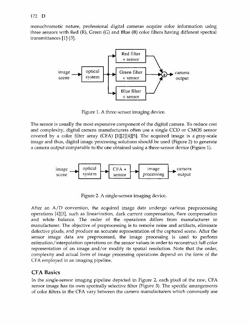
172 D
monochromatic nature, professional digital cameras acquire color information using three sensors with Red (R), Green (G) and Blue (B) color filters having different spectral transmittances [l]-[3].
image ^ scene
optical system
r->-
r- ^ ^ w
- >
Red filter + sensor
Green filter + sensor
Blue filter + sensor
^ti 1 • ^ 1
^ camera output
Figure 1. A three-sensor imaging device.
The sensor is usually the most expensive component of the digital camera. To reduce cost and complexity, digital camera manufacturers often use a single CCD or CMOS sensor covered by a color filter array (CFA) [1][2][4][5]. The acquired image is a gray-scale image and thus, digital image processing solutions should be used (Figure 2) to generate a camera output comparable to the one obtained using a three-sensor device (Figure 1).
image ^ scene
optical system — • CFA +
sensor — > •
image processing
^camera output
Figure 2. A single-sensor imaging device.
After an A/D conversion, the acquired image data undergo various preprocessing operations [4] [5], such as linearization, dark current compensation, flare compensation and white balance. The order of the operations differs from manufacturer to manufacturer. The objective of preprocessing is to remove noise and artifacts, eliminate defective pixels, and produce an accurate representation of the captured scene. After the sensor image data are preprocessed, the image processing is used to perform estimation/interpolation operations on the sensor values in order to reconstruct full color representation of an image and/or modify its spatial resolution. Note that the order, complexity and actual form of image processing operations depend on the form of the CFA employed in an imaging pipeline.
CFA Basics In the single-sensor imaging pipeline depicted in Figure 2, each pixel of the raw, CFA sensor image has its own spectrally selective filter (Figure 3). The specific arrangements of color filters in the CFA vary between the camera manufacturers which commonly use

Encyclopedia of Multimedia 173
RGB CFAs. Alternative solutions include arrays constructed using Cyan-Magenta-Yellow (CMY) complementary colors, color systems with mixed primary/complementary colors, and arrays with more than three colors with spectrally shifted color [2] [4].
R G B R G B R G B
miRm EHHHIi H E B S I H H E H
R G B R G B R G B
light
I I H H I M H i B I H I I ^olor filter
sensor cell
Figure 3. CFA based image acquisition.
Among these, the Bayer pattern (Figure 4) [9] is commonly used due to simplicity of the subsequent processing steps. This pattern contains twice as many G components compared to R or B components reflecting the fact that the spectral response of Green filters is close to the luminance response of human visual system [8].
W^ D
^^n^^H
^^M^^l
^ ^ ^ ^^P^^H
^^^^^H
- : • . . - , : F l
B Figure 4. Bayer CFA pattern [9] with a GRGR phase in the first row.
Image Processing for Color Estimation After the CFA image is captured, numerous image processing operations can be implemented in the camera pipeline (Figure 5). The most critical step in a single-sensor imaging pipeline is a process called demosaicking or CFA interpolation [1][2][10][11]. Demosaicking is used to estimate the two missing components in each spatial location of a CFA sensor image and convert a gray-scale, mosaic-like, CFA image to a full-color image. It performs spectral interpolation operations [12]. Since demosaicking solutions usually introduce various visual impairments, such as blurred edges and color shifts, the quality of demosaicked camera images should be enhanced using demosaicked image postprocessing [13],[14]. By operating on a demosaicked, full-color, image input the postprocessor performs full color image enhancement [14]. Apart from demosaicking and demosaicked image postprocessing, zooming operations are probably the most
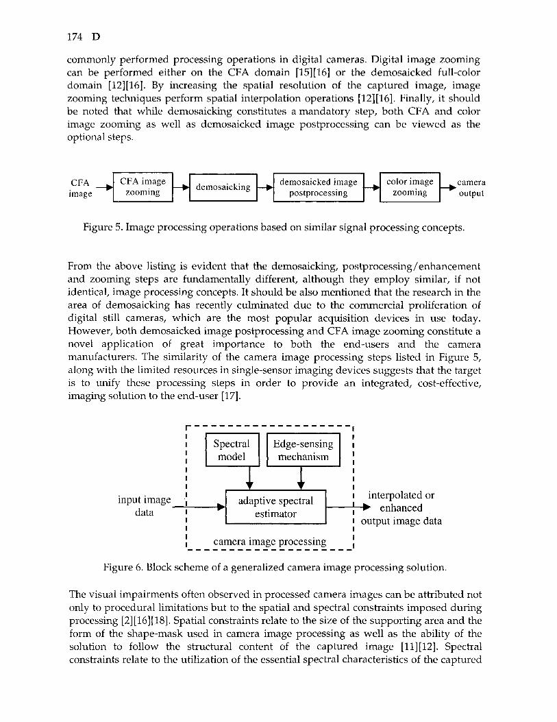
174 D
commonly performed processing operations in digital cameras. Digital image zooming can be performed either on the CFA domain [15] [16] or the demosaicked full-color domain [12][16]. By increasing the spatial resolution of the captured image, image zooming techniques perform spatial interpolation operations [12] [16]. Finally, it should be noted that while demosaicking constitutes a mandatory step, both CFA and color image zooming as well as demosaicked image postprocessing can be viewed as the optional steps.
CFA image
CFA image zooming —> demosaicking — •
demosaicked image postprocessing — •
color image zooming
camera output
Figure 5. Image processing operations based on similar signal processing concepts.
From the above listing is evident that the demosaicking, postprocessing/enhancement and zooming steps are fundamentally different, although they employ similar, if not identical, image processing concepts. It should be also mentioned that the research in the area of demosaicking has recently culminated due to the commercial proliferation of digital still cameras, which are the most popular acquisition devices in use today. However, both demosaicked image postprocessing and CFA image zooming constitute a novel application of great importance to both the end-users and the camera manufacturers. The similarity of the camera image processing steps listed in Figure 5, along with the limited resources in single-sensor imaging devices suggests that the target is to unify these processing steps in order to provide an integrated, cost-effective, imaging solution to the end-user [17].
1
input image , data 1
Spectral model
^ w
cai
1 r
Edge-sensing mechanism
1 r
adaptive spectral estimator
nera im la e proce jssing
1 interpolated or
• { • enhanced 1 output image data
Figure 6. Block scheme of a generalized camera image processing solution.
The visual impairments often observed in processed camera images can be attributed not only to procedural limitations but to the spatial and spectral constraints imposed during processing [2][16][18]. Spatial constraints relate to the size of the supporting area and the form of the shape-mask used in camera image processing as well as the ability of the solution to follow the structural content of the captured image [11] [12]. Spectral constraints relate to the utilization of the essential spectral characteristics of the captured
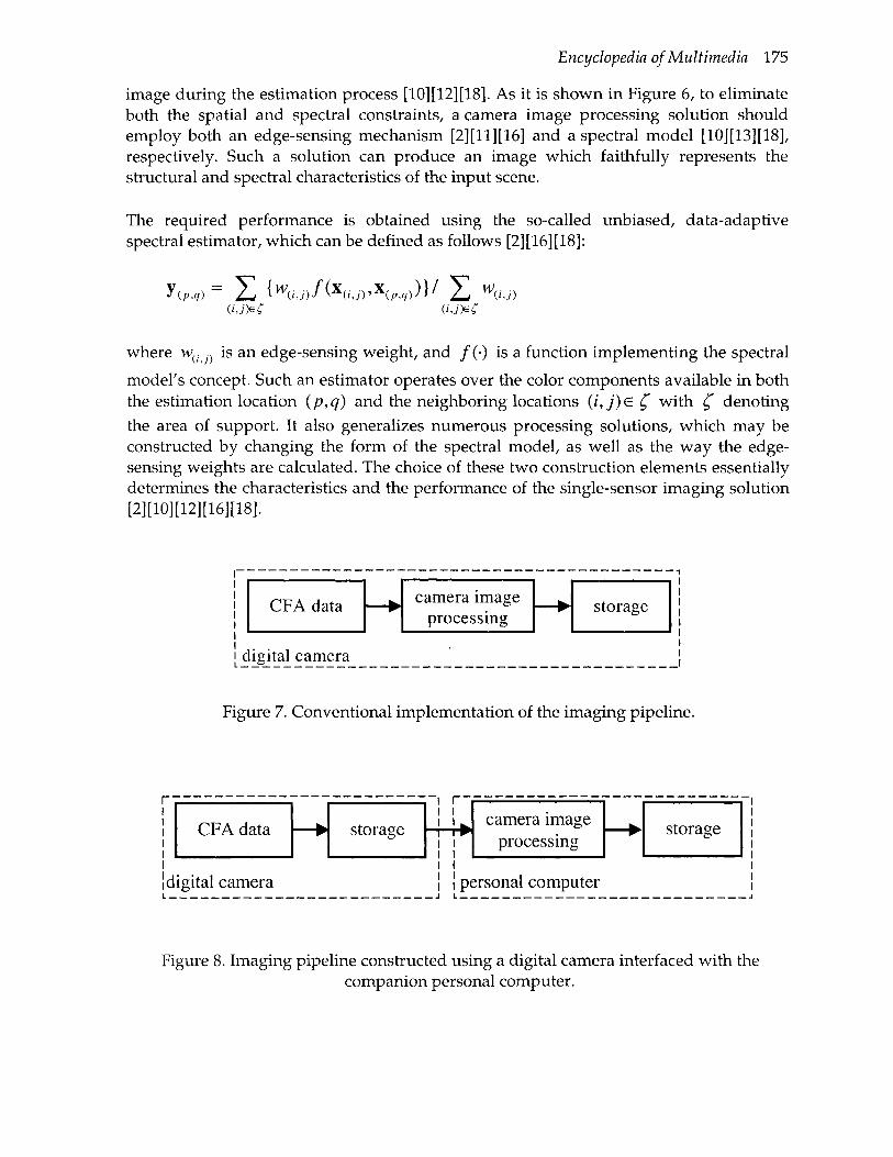
Encyclopedia of Multimedia 175
image during the estimation process [10][12][18]. As it is shown in Figure 6, to eHminate both the spatial and spectral constraints, a camera image processing solution should employ both an edge-sensing mechanism [2][11][16] and a spectral model [10][13][18], respectively. Such a solution can produce an image which faithfully represents the structural and spectral characteristics of the input scene.
The required performance is obtained using the so-called unbiased, data-adaptive spectral estimator, which can be defined as follows [2][16][18]:
(p,q) Z {^(/J)/KJ)'X(P,.)))/ Z %.) (iJ)^C (iJ)eC
where w , j^ is an edge-sensing weight, and /(•) is a function implementing the spectral
model's concept. Such an estimator operates over the color components available in both the estimation location {p,q) and the neighboring locations (i,j)E ^ with ^ denoting the area of support. It also generalizes numerous processing solutions, which may be constructed by changing the form of the spectral model, as well as the way the edge-sensing weights are calculated. The choice of these two construction elements essentially determines the characteristics and the performance of the single-sensor imaging solution [2][10][12][16][18].
1 C 1 .-
CFA data
iigital camera
camera image processing
^ p storage
Figure 7. Conventional implementation of the imaging pipeline.
1
Id
CFA data
igital camera
^ w
storage 1 r
1 1 P
1 Ip^
camera image processing
arsenal computer
— • storage
Figure 8. Imaging pipeline constructed using a digital camera interfaced with the companion personal computer.

176 D
Depending on the application requirements and implementation constraints, an imaging solution can be implemented either in a digital camera or in a companion personal computer (PC). The architecture shown in Figure 7 is suitable for a computationally efficient method useful for practical, cost-effective camera solutions operating in the real-time constraints. Potentially demanding solutions may be included in the architecture shown in Figure 8. Unlike the conventional solution, using the PC-based pipeline the end-user can control the processing operation, change the parameter setting of the processing solution, and re-run the procedure if the output image does not satisfy the quality requirements.
Camera Image Compression The outputted camera images (Figures 7 and 8) are usually stored either in a CFA format or as full-color images [4] [5] [19]. Most professional digital cameras follow the so-called tagged image file format for electronic photography (TIFF-EP) for image storage. In this format, the raw CFA image is stored along with additional information, such as the details about camera setting, spectral sensitivities, and illuminant used. Consumer digital cameras store the full-color image in a compressed format using the Joint Photographic Experts Group (JPEG) standard. However, exchangeable image file (EXIF) format has been popularized due to its easy implementation and possibilities to store additional (metadata) information about the camera and the environment.
Current research in camera image compression indicates that the use of JPEG compression on the CFA image data may lead to new and promising imaging solutions which can be of great interest in wireless imaging-enabled devices since it allows for the transmission of significantly less information compared to the full-color image compression solutions [19]. Further improvements may be expected using JPEG2000 which is a new standard for digital still image compression.
Video-Demosaicking Recent advances in hardware and digital image/signal processing have allowed to record motion video or image sequences using digital still image or digital video single sensor cameras. Such a visual input can be viewed as a three-dimensional image signal or a time sequence of two-dimensional still images, and it usually exhibits significant correlation in both the spatial and temporal sense [20]. Single-sensor camera image processing solutions devised for still images can also be used in single-sensor video cameras, however by omitting the essential temporal characteristics, conventional camera image processing methods, viewed as spatial solution which process separately the individual frames, produce an output video sequence with motion artifacts. Therefore, a well designed video processing technique should follow the representation of the signal, and utilize all the available information during operation. Such a spatiotemporal solution (Figure 9) should use the spatial, temporal, spectral and structural characteristics of the captured CFA video to produce a full-color, demosaicked, image sequence at the output [20].
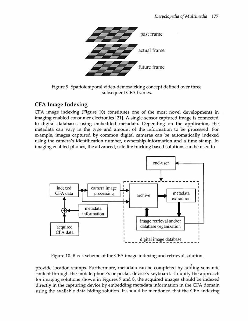
Encyclopedia of Multimedia 177
Figure 9. Spatiotemporal video-demosaicking concept defined over three subsequent CFA frames.
CFA Image Indexing CFA image indexing (Figure 10) constitutes one of the most novel developments in imaging enabled consumer electronics [21]. A single-sensor captured image is connected to digital databases using embedded metadata. Depending on the application, the metadata can vary in the type and amount of the information to be processed. For example, images captured by common digital cameras can be automatically indexed using the camera's identification number, ownership information and a time stamp. In imaging enabled phones, the advanced, satellite tracking based solutions can be used to
indexed CFA data
t 1 fflH
T acquired
1 CFA data
-i fW camera image
processing
metadata information
r -
- } - •
j W
CllU.-u^C'i
archive
t
^ r
^ ^ 1
metadata extraction
1 - 1 L image retrieval and/or database organization
] digital image database i
Figure 10. Block scheme of the CFA image indexing and retrieval solution.
provide location stamps. Furthermore, metadata can be completed by adding semantic content through the mobile phone's or pocket device's keyboard. To unify the approach for imaging solutions shown in Figures 7 and 8, the acquired images should be indexed directly in the capturing device by embedding metadata information in the CFA domain using the available data hiding solution. It should be mentioned that the CFA indexing

178 D
approach can also be used to embed the metadata information which is achieved in EXIF format. Since such information is currently written in the header of the stored file only, it can easily lost by changing the file format or modifying the captured image using any conventional graphic software.
The metadata information should be extracted from either the CFA images or the demosaicked images in personal image databases using PC software commonly available by camera manufacturers (Figure 10). Alternatively, conventional public image database tools such as the well-known World Wide Media eXchange (WWMX) database can be used instead. Thus, the CFA image indexing approach helps to authenticate, organize and retrieve images in digital databases [21].
See: Demosaicking, CFA image zooming, Demosaicked image postprocessing. Color image zooming. Edge-sensing mechanism. Spectral model. Color image filtering and enhancement. Image secret sharing.
References 1. R. Lukac, K.-N. Plataniotis, D. Hatzinakos, and M. Aleksic, "A Novel Cost Effective
Demosaicing Approach," IEEE Transactions of Consumer Electronics, Vol. 50, No. 1, February 2004, pp. 256-261.
2. R. Lukac and K.-N. Plataniotis, "Data-Adaptive Filters for Demosaicking: A Framework," IEEE Transactions of Consumer Electronics, submitted.
3. M. Vrhel, E. Saber, and H.-J. Trusell, "Color Image Generation and Display Technologies," IEEE Signal Processing Magazine, Vol. 22, No. 1, January 2005, pp. 23-33.
4. K. Parulski and K.-E. Spaulding, "Color Image Processing for Digital Cameras," in Digital Color Imaging Handbook, (Eds.) G. Sharma, CRC Press, Boca Raton, FL, 2002, pp. 728-757.
5. R. Ramanath, W.-E. Snyder, Y. Yoo, and M.-S. Drew, "Color Image Processing Pipeline," IEEE Signal Processing Magazine, Vol. 22, No. 1, January 2005, pp. 34-43.
6. P.-L.-P. Dillon, D.-M. Lewis, and F.-G. Kaspar, "Color Imaging System Using a Single CCD Area Array," IEEE Journal of Solid-State Circuits, Vol. 13, No. 1, February 1978, pp. 28-33.
7. T. Lule, S. Benthien, H. Keller, F. Mutze, P. Rieve, K. Seibel, M. Sommer, and M. Bohm, "Sensitivity of CMOS Based Imagers and Scaling Perspectives," IEEE Transactions of Electronic Devices, Vol. 47, No. 11, November 2000, pp. 2110-2122.
8. G. Wyszecki and W. S. Stiles, "Color Science, Concepts and Methods, Quantitative Data and Formulas," John Wiley, N.Y., 2nd Edition, 1982.
9. B. E. Bayer, "Color imaging array," U.S. Patent 3 971 065, July 1976. 10. R. Lukac and K.-N. Plataniotis, "Normalized Color-Ratio Modeling for CFA
Interpolation," IEEE Transactions of Consumer Electronics, Vol. 50, No. 2, May 2004, pp. 737-745.
11. B.-K. Gunturk, J. Glotzbach, Y. Altunbasak, R.-W. Schaffer, and R.-M. Murserau, "Demosaicking: Color Filter Array Interpolation," IEEE Signal Processing Magazine, Vol. 22, No. 1, pp. 44-54, January 2005.

Encyclopedia of Multimedia 179
12. R. Lukac, B. Smolka, K. Martin, K.-N. Plataniotis, and A.-N. Venetsanopulos, "Vector Filtering for Color Imaging," IEEE Signal Processing Magazine, Vol. 22, No. 1, January 2005, pp. 74-86.
13. R. Lukac, K. Martin, and K.-N. Plataniotis, "Demosaicked Image Postprocessing Using Local Color Ratios," IEEE Transactions of Circuits and Systems for Video Technology, Vol. 14, No. 6, June 2004, pp. 914-920.
14. R. Lukac and K.-N. Plataniotis, "A Robust, Cost-Effective Postprocessor for Enhancing Demosaicked Camera Images," Real-Time Imaging, Special Issue on Spectral Imaging II, Vol. 11, 2005.
15. R. Lukac and K.-N. Plataniotis, "Digital Zooming for Color Filter Array Based Image Sensors," Real-Time Imaging, Special Issue on Spectral Imaging II, Vol. 11, 2005.
16. R. Lukac, K.-N. Plataniotis, and D. Hatzinakos: "Color Image Zooming on the Bayer Pattern," IEEE Transactions on Circuit and Systems for Video Technology, Vol. 15, 2005.
17. R. Lukac, K. Martin, and K.-N. Plataniotis, "Digital Camera Zooming Based on Urufied CFA Image Processing Steps," IEEE Transactions of Consumer Electronics, Vol. 50, No. 1, February 2004, pp. 15-24.
18. R. Lukac and K.-N. Plataniotis, "A Vector Spectral Model for Digital Camera Image Processing," IEEE Trans. Circuit and Systems for Video Technology, submitted.
19. C.-C. Koh, J. Mukherjee, and S.-K. Mitra, "New Efficient Methods of Image Compression in Digital Cameras with Color Filter Array," IEEE Trans. Consumer Electronics, Vol. 49, No. 4, November 2003, pp. 1448-1456.
20. R. Lukac and K.-N. Plataniotis, "Fast Video Demosaicking Solution for Mobile Phone Imaging Applications," IEEE Transactions of Consumer Electronics, submitted.
21. R. Lukac and K.-N. Plataniotis, "Digital Image Indexing Using Secret Sharing Schemes: A Unified Framework for Single-Sensor Consumer Electronics," IEEE Transactions of Consumer Electronics, submitted.
DIGITAL CINEMA
Definition: Digital cinema includes new computer technologies including the creation of synthetic images, to produce action movies.
While traditional way to make, distribute and consume cinema is becoming obsolete, the IT is promoting the emergence of technologies of digital cinema [1]. Rendering engines can now produce synthetic images in a so realistic way that they can be integrated in a high quality live action movie. Results obtained with digital cinema technologies range from post production effects, such as removing an actor's blemish or fixing a light, to digital animations, such as creating scene where real actors live together with synthetic characters (think Gollum in the Lord of the Rings). Since then, Hollywood has begun a technological revolution creating movies previously impossible to display convincingly, such as, for example, Jurassic Park, Terminator 2, Star Wars, Shrek, Toy Story and Monster Inc. To create this kind of movies a great computational power is needed based on modern hardware (CPUs) and software (Linux OS) equipments. CPUs work as coprocessors to CPUs, adopting a fast AGP bus [2]. Intense competition has driven this field to produce a new GPU generation every six months. The most innovative

180 D
companies such as Nvidia and ATI, make their GPUs programmable in assembly providing spectacular computer graphical facilities up to the limit threshold of a new art form.
The open source nature and the no license cost of Linux made it one of the best candidates for supporting graphic workstations. For example, super computer like the Cray X-MP ( used in the 1985's "The Last Starfighter"), have been abandoned in favor of now cheaper dual-processor Pentium SGI 1100 Linux OS-based servers exploited for realizing the special effects of "the Lord of the Rings" movies. Generally speaking, producing a digital movie eliminates different disadvantages: the celluloid film quality deteriorate through the duplication process, further analogical projectors make the film prone to harmful intermittent mechanical movement. Moreover, the advent of the Internet era, digital distribution could be offered on demand. Studios equipped with digital cinema equipments and broadband Internet access can download the film on the flight thus scheduling faster the coming soon. Moreover, the digital cinema eliminates different disadvantages, and it facilitates the duplication from piracy. While the cost offers resistance to digital cinema yet, innovations in home entertainment push the development of this technology. As of today, the of-the-shelf home theater market offers large televisions, digital projectors, Dolby 5.1 sound systems at a reasonable prize. In practice, it is possible to re-create a small-scale cinema with a high quality at home. Some people claim that the underlying social issues keep attractive the old celluloid cinema for a long time. Obviously, this is a topic to be investigated in the social field. Still, one of the major technological challenges is how to improve the sensorial experiences of the consumers. Possible solutions are exploring 3D stereographic, IMAX, surround sound systems and haptic technologies [3].
See: Multimedia Entertainment Applications
References 1. J. Korris and M. Macedonia, "The End of Celluloid: Digital Cinema Emerges," IEEE
Computer, Vol. 34, No. 4, April 2002, pp. 96-98. 2. M. Macedonia, "The GPU Enter Computing Mainstream," IEEE Computer, Vol. 36,
No. 10, October 2003, pp. 106-108. 3. M.OUis and T. Williamson, "The Future of 3D Video," IEEE Computer, Vol. 34, No. 6,
June 2001, pp.97-99.
DIGITAL INPAINTING
Timothy K, Shih, Rong-Chi Change Su-Mei Chou, Yu-Ping Chen, and Huan-Chi Huang Tamkang University, Taiwan
Definition: Digital inpainting is a technique to automatically restore partially damaged photos, repair aged movies, or fill holes on 3D surfaces.

Encyclopedia of Multimedia 181
Digital inpainting requires fundamental knowledge in image processing, video coding, and 3D geometric. Certainly, these topics are important issues in multimedia computing. This article summarizes a few challenge issues in digital inpainting and presents some solutions in the literature. We divide the article into three short sections for each problem (i. e., image, video, and 3D surface). Several short articles (included in this book) related to this article further explain additional issues on image and video inpainting.
Image Inpainting Aged photos and paintings can be damaged either by scratch, dirt, or other reasons. Even though it is not possible to restore a painting to its original, to repair damaged artifacts with a visually pleasant result is useful, especially for examples in digital museum projects. One of the simplest but efficient mechanisms was presented in [4]. The diffusion kernel is able to repair damages of small area with a barrier to deal with high contrast edges. The computation presented in [4] is proved to be very fast. By using a similar interpolation concept, with an extension to allow different thresholds on different interpolated pixels [8], the mechanism discussed in [8] allows an adaptive computation scheme. Thus, inpainted pixels far away from inpainting boundary can be calculated to achieve a better visual result. Considering inpainting from another perspective, the concept of isophote lines arriving at the boundary of an inpainted area is introduced in [1]. By preventing crossed isophote lines, the mechanism can partially preserve structural information in a damaged image. Other works [2, 3] uses concepts on fluid-dynamics and curvature-driven diffusions for image inpainting. Basically, an image with continuous color and intensity levels can be treated as a two dimensional fluid object. The mathematical model derived in [2, 3] achieve a reasonable result of image inpainting.
On the other hand, a multiple resolution approach is used in [12]. The damaged picture is decomposed into several levels, depending on the color variations of the picture. Interpolated pixels are calculated according to its coordination relation with respect to useful surrounding information (see Figure 1). The algorithm is summarized in the article entitled "Multi-Resolution Image Inpainting" in this book.
Figure 1. A damaged photo and its restored image in [12].
The algorithm is further extended for painting [14]. A painting can be separated into several layers according to color distributions. Each layer is inpainted separately. The

182 D
results are merged to obtain a reconstructed image (see Figure 2). The inpainting strategy use in [14] is similar to the algorithm used in [12]. However, to merge inpainted results from different layers, a layer fusion algorithm is necessary. The fusion algorithm follows a strategy. For each damaged pixel to be inpainted, two consecutive layers are compared. A window with pixels in a distance with respect to an inpainted pixel is used. A function computes percentages of useful pixels within the distance is applied to each inpainted pixel. Depending on the percentages, a layer is selected. Useful pixels are non-inpainted pixels from the original image, with respect to a layer. The far ground is firstly placed in a blank paper. The picture is restored with a darker layer step-by-step. In Chinese painting, light far grounds are drawn first, followed by darker grounds. The restoring strategy achieves a similar effect.
Figure 2. A Chine painting is repaired according to algorithms in [14].
The work discussed in [12] and [14] also points out an issue of what type of images that can be restored easily. In general, pixel interpolation is suitable for images with continuous color and intensity, for instance, photos. Images with concrete boundaries, such as cartoon drawing, are hard to appreciate pixel interpolation. To restore cartoon pictures one need to use line detection and heuristics.
The above works are computations on special domain of an image via pixel interpolation or extrapolation. With proper heuristics, structural information can be reconstructed to achieve a reasonable effect. However, sometimes, the resulting image is blurred. One drawback of the spatial domain approach is that textural information is hard to restore. The work discussed in [6] uses a multi-resolution texture synthesis mechanism to combine both spatial and frequency information, which can achieve a better result to restore textures. Another example combining spatial and frequency information for restoration is also found in [7].
Algorithms discussed above are effective and efficient in restoring damages of small and discontinue areas. To restore damages of larger area, for instance, to remove a person from a picture, it is necessary to take another approach. Simple pixel interpolation or texture synthesis is not able to produce a visually pleasant result. One useful approach is to copy background information from the same picture to replace the selected area (e.g., a person). The exemplar-based synthesis approach [9] computes a priority for each patch to be selected to inpaint the removed area. After a target area is inpainted, a confidence
Encyclopedia of Multimedia 183
value is assigned or re-computed. The confidence values are them used for computing the next inpainting area. The following briefly summarizes the approach discussed in [9]:
Let O be the source region, Let Q be a manually selected target region and S^ be the contour of Q, Repeat until region Q is empty
Compute boundary SO. and priorities P(p) Propagate texture and structure information
Find patch ^ p on S^ with highest priority P(p) Find patch Wq in O which minimizes Sum_of_Square_Difference(^p, M'q) Copy Wq to Yp
Update confidence values
Essentially, Q is an area to be inpainted, with its contour XI. Patches on this contour are associated with priorities (representing order to be inpainted). Useful patches ^ q from the source region O are compared to partial patch on the contour. Best match is selected and copied to the candidate patch. In a few iterations, all candidate patches in the contour are inpainted. This concludes an inpainting step on the contour. The confidence values on inpainted patches are re-computed. And, the same inpainting procedure on the next contour continues, until the target region is empty.
The work discussed in [13] also uses a confidence map (values) and adaptive neighborhood search (finding useful patch of the highest priority). In addition, the picture is refined from coarse level to fine level, which will take several iterations on the same inpainted area. The initial inpainted information relies on a fast estimation scheme known as the push-pull filtering method, to down-sample and up-sample the image in a multi-resolution hierarchically. The algorithm presented in [13] is summarized below:
Let a' be an inverse matte, with a conference value between 0 and 1 for each pixel For each scale from coarse to fine
Approximate image from color and coarser scale Compute confidence map from a' and coarser scale Compute level set from confidence map While mean confidence < 1 - E
For next target position p Compute adaptive neighborhood N(p) Search for most similar and frequent source match A ( ) Composite N(p) and A ( ) at/?, updating color and a' Compute approximation, confidence map and update level set
Considering image inpainting form another perspective, inpainting technique can be used to attack visible watermarks [5]. Even the mechanism can not completely remove the watermark, since the visible watermark is half transparent (i.e., watermark pixels are interpolated with underlying pixels), it is possible to extend this mechanism to recover aged photos with pasted Scotch taps (half transparent).
Next, an important issue related to image inpainting should be discussed. Most image inpainting algorithms rely on the user to explicitly select a region for repairing or object

184 D
removal. This is due to the fact that detection of damaged area is hard to achieve automatically, especially on a single image (i.e., compared to motion picture with several images for cross reference). Damaged areas by ink or scratch are created naturally. It is not easy to separate these areas from a scene taken by a camera, which is created naturally as well. It is almost impossible to precisely distinguish the damages by a mathematical function precisely. However, a naive mechanism developed at Tamkang University is able to detect ink and scratch damages manually created (see Figures 3 and 4). The mechanism uses image processing techniques to find variation of color segments in the picture. With some heuristic rules, the mechanism is able to tell the type of damages (i.e., by ink or by scratch). The black/blue ink traces and scratch in Figures 3 and 4 (as well as other 100 pictures) are created on real photos and scanned for testing. Detected damaged areas are shown in red/yellow. However, there are limitations of the detection mechanism. Extra thin lines and small dots produced from scratch and ink are hard to detect. Ink damages of irregular shape can be mixed with natural objects of dark colors. We are taking a multi-resolution approach to solve the problem. With an improved detection mechanism, a fully automatic system can be implemented for repairing damaged photos in a digital library project.
MP- "
•
m
(bl) (b2)
Figure 3. Different color of ink traces (al, bl) are detected (a2, b2).
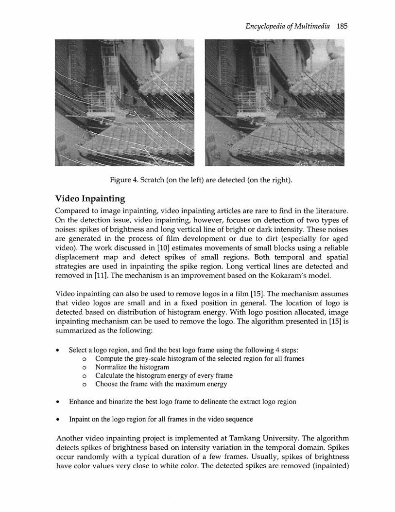
Encyclopedia of Multimedia 185
Figure 4. Scratch (on the left) are detected (on the right).
Video Inpainting Compared to image inpainting, video inpainting articles are rare to find in the literature. On the detection issue, video inpainting, however, focuses on detection of two types of noises: spikes of brightness and long vertical line of bright or dark intensity. These noises are generated in the process of film development or due to dirt (especially for aged video). The work discussed in [10] estimates movements of small blocks using a reliable displacement map and detect spikes of small regions. Both temporal and spatial strategies are used in inpainting the spike region. Long vertical lines are detected and removed in [11]. The mechanism is an improvement based on the Kokaram's model.
Video inpainting can also be used to remove logos in a film [15]. The mechanism assumes that video logos are small and in a fixed position in general. The location of logo is detected based on distribution of histogram energy. With logo position allocated, image inpainting mechanism can be used to remove the logo. The algorithm presented in [15] is summarized as the following:
• Select a logo region, and find the best logo frame using the following 4 steps: o Compute the grey-scale histogram of the selected region for all frames o Normalize the histogram o Calculate the histogram energy of every frame o Choose the frame with the maximum energy
• Enhance and binarize the best logo frame to delineate the extract logo region
• Inpaint on the logo region for all frames in the video sequence
Another video inpainting project is implemented at Tamkang University. The algorithm detects spikes of brightness based on intensity variation in the temporal domain. Spikes occur randomly with a typical duration of a few frames. Usually, spikes of brightness have color values very close to white color. The detected spikes are removed (inpainted)

186 D
using information from both spatial and temporal domains. Best results, if any, are used from temporal domains since it is possible to recover the lost using the same object property (assuming that the moving object is inpainted). Otherwise, interpolation of pixels is applied using information in the same frame. Figure 5 show an example of spikes in an aged movie by Jacky Chen. The spikes, detected regions, and a restored frame are all shown in Figure 5. Most spikes are detected. However, the ratio of miss detection is increased if a threshold of spike size is set to very small. But, for incorrect detection, the detected small areas are inpainted as well. In general, the visual result, even with miss detections, is pleasant in the inpainted video as compared to seeing lots of spikes.
Figure 5. Video inpainting results - the damaged frame (left), the detected spikes shown in red (middle), and the repaired frame (right).
Holes Removal on 3-D Surfaces Three dimensional scanners are important for creating avatars or models in virtual reality and augmented reality. However, due to many reasons, such as occlusions, low reflectance, scanner placement, lack of sufficient coverage, etc, 3-D surfaces produced from scanner may have holes. In most situations, watertight surfaces are required. Algorithms to overcome this problem in most scanners use triangulating boundaries calculation. However, it is possible to produce self-intersecting surfaces. A solution using volumetric diffusion was proposed in [16,17]. The algorithms proposed always produces closed, manifold triangle mesh without self-intersections.
Summary Digital inpainting is part of multimedia computing research. This article summarizes inpainting techniques used in image, video, and 3D surfaces. Some techniques can be
Encyclopedia of Multimedia 187
found in image processing literature (i.e., pixel interpolation). Others such as motion estimation algorithms can be found in video coding standard specifications. Digital inpainting techniques are useful and can be used in restoration of aged pictures and films. The approach is different from some signal processing mechanisms which eliminates noises by sacrificing quality of the original multimedia resource.
This interesting research area still has some issues that can be further investigated. For instance, it is possible that different categories of images (e.g., painting, photo, and cartoon drawing) require different inpainting strategies. Also, the assessment strategy needs to be investigated since PSNR values do not always reveal correct visual results. Human evaluation is necessary. For inpainting large blocks on images, it is not possible to inpaint properly unless semantics are considered. Also, exemplar-based technique can consider searching on patches from another picture instead of on the same picture. Thus, an image repository classified according to some semantic criteria is necessary. Most image inpainting tools allow users to select a solid region for inpainting. A fuzzy mask can be added to the region such that partial information from the damaged area can be used. Finally, there is no article of "audio inpainting" found in the literature. It will be interesting if audio inpainting can be used in radio signal transmission.
See: Multi-Resolution Image Inpainting, Motion Picture Inpainting on Aged Films, Photo Defect Detection
References 1. M. Bertalmio, G. Sapiro, V. Caselles, and C. Ballester, "Image Inpainting,"
Proceedings of the ACM SIGGRAPH Conference on Computer Graphics, SIGGRAPH 2000, pp.417-424.
2. M. Bertalmio, A. Bertozzi, and G. Sapiro, "Navier-Stokes, Fluid-Dynamics and Image and Video Inpainting," Proceedings of the 2001 IEEE Computer Society Conference on Computer Vision and Pattern Recognition, 2001, pp. I355-I362.
3. T.-F. Chan and J. Shen, "Nontexture Inpainting by Curvature-Driven Diffusions," Journal of Visual Communication and Image Representation, Vol. 12, No. 4, 2001, pp. 436-449.
4. M. M. Oliveira, B. Bowen, R. McKenna, and Y.-S. Chang, "Fast Digital Image Inpainting," Proceedings of the International Conference on Visualization, Imaging and Image Processing (VHP 2001), 2001, pp. 261-266.
5. C.-H. Huang and J.-L. Wu, "Inpainting Attacks against Visible Watermarking Schemes," Proceedings of the SPIE, International Society for Optical Engineering, 2001, No. 4314, pp. 376-384.
6. H. Yamauchi, J. Haber, and H.-P. Seidel, "Image Restoration Using Multiresolution Texture Synthesis and Image Inpainting," Computer Graphics International, 2003, pp. 108-113.
7. M. Bertalmio, L. Vese, G. Sapiro, and S. Osher, "Simultaneous Structure and Texture Image Inpainting," IEEE Transactions on Image Processing, Vol. 12, No. 8, 2003 pp. 882 -889.
8. R. Bornard, E. Lecan, L. Laborelli, and J.-H. Chenot, "Missing Data Correction in Still Images and Image Sequences," ACM Multimedia, 2002, pp. 355 - 361.
188 D
9. A. Criminisi, P. Perez, and K. Toyama, "Region Filling and Object Removal by Exemplar-Based Image Inpainting," IEEE Transactions Image Processing, Vol. 13, 2004, pp. 1200-1212.
10. A. Machi and F. Collura, "Accurate spatio-temporal restoration of compact single frame defects in aged motion picture," Proceedings of 12th International Conference on Image Analysis and Processing, September 2003, pp. 454 - 459.
11. L. Joyeux, O. Buisson, B. Besserer, and S. Boukir, "Detection and removal of line scratches in motion picture films," IEEE Conference on Computer Vision and Pattern Recognition, June 23-25,1999 pp. 548 - 553.
12. T. K. Shih., L.-C. Lu, and R.-C. Chang, "Multi-Resolution Image Inpainting," Proceedings of IEEE International Conference on Multimedia & Expo (ICME'03), July 2003, pp. 485-488.
13. I. Drori, D. Cohen-Or, and H. Yeshurun, "Fragment-Based Image Completion," Proceedings of ACM SIGGRAPH 2003, pp. 303-312.
14. T. K. Shih, R.-C. Chang, and L.-C. Lu, "Multi-Layer Inpainting on Chinese Artwork," Proceedings of IEEE International Conference on Multimedia & Expo (ICME'04), June 2004, pp. 33-36.
15. W.-Q. Yan and M. S. Kankanhalli, "Erasing Video Logos Based on Image Inpainting," Proceedings of IEEE International Conference in Multimedia and Expo (ICME 2002), Vol. 2, 2002, pp. 521-524.
16. J. Verdera, V. Caselles, M. Bertalmio, and G. Sapiro, "Inpainting Surface Holes," Proceedings of IEEE International Conference on Image Processing, Vol. 2, 2003, pp. 903-906.
17. J. Davis S. R. Marschner, M. Garr, and M. Levoy, "Filling Holes in Complex Surfaces Using Volumetric Diffusion", Proceedings of First International Symposium on 3D Data Processing, Visualization, Transmission, (3DPVT'02), 2002, pp. 858-862.
DIGITAL RIGHTS MANAGEMENT
Pallavi Shah Hewlett Packard
Definition: Digital Rights Management technology offers the ability to control the distribution and use of the intellectual property (including media/content) and thereby protect the associated revenue or investment for the digital content businesses.
What is Digital Rights Management? Digital Rights management is a key enabler of end to end digital content business models. Historically, Digital Rights Management is viewed primarily as the security technology used for protection of digital media copyright. However, what differentiates DRM from traditional security technologies is its ability to control content dynamically and persistently by setting policy. Policy provides regulations on the types of actions (like record, copy, play, print, view x number of times, etc.) that can be performed on the

Encyclopedia of Multimedia 189
content along with the timeframe in which the content is accessible. The policy is set by the IP or content owners.
Why DRM? Everything a person buys has legal restrictions that determine what can and cannot be done with the media assets. If an individual consumer buys a traditional printed book at a bookstore, he or she is given some rights to the content of the book as an owner of the book. The consumer can read the book, lend it to someone, or give it away.
But by law, the purchaser cannot make copies of the book and sell them. As an institutional consumer (public or private company, or educational facility), the rights to copyright reuse with a printed book or physical piece of media (CD, DVD, audio tape, microfiche, etc.) are the same as the individual consumer, but the notion of "fair use" is instituted when it comes to copyright protection. Institutions can invoke "fair use" of copying copyrighted materials for internal distribution for educational or research purposes without breaking copyright laws.
The traditional media world (publishing, music, movies, etc.) is very simple and limited to basic contractual rights. The objectives for managing content rights in the traditional media world include deterring piracy and protecting the content, enabling revenue through outright purchase or licensing, bolstering traditional media brands, and learning more about a company's audience. It is because there is a tangible asset related to each piece of data that is recorded (as a whole or in pieces) that "fair use" can be managed more appropriately in the printed or physical media world. It is much more complex in the digital world. Content conversion, digitization, compression, and storage technologies have created new opportunities and efficiencies for media and information to be archived, repackaged, and redistributed through electronic channels (e.g., the Internet, extranets, cable, terrestrial broadcasts, or satellites). As content becomes more widely available in digital form, it becomes even easier to distribute, share, copy, and alter if it is improperly "meta-tagged" (unique identifying tags related to media format, creator, usage, and distribution rules) and encrypted throughout the digital distribution value chain.
This brings an exponential increase in the threat of piracy and the loss of revenue for original content owners and producers.
Now that electronic content can be copied much more easily, content owners have a greater need for content control. IP authentication and password access are not able to protect the content from being duplicated or shared, thus creating a need for greater rights management controls. At the same time, digital media distribution can bring a variety of new business opportunities for owners or generators of content who incorporate the right technologies to control their digital media distribution value chain.
Technology / Architecture Overview: There are 2 entities in the content business: the publisher and the consumer.
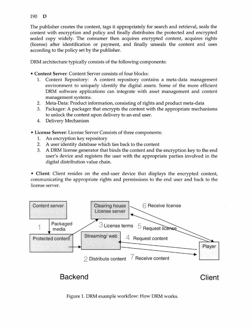
190 D
The publisher creates the content, tags it appropriately for search and retrieval, seals the content with encryption and policy and finally distributes the protected and encrypted sealed copy widely. The consumer then acquires encrypted content, acquires rights (license) after identification or payment, and finally unseals the content and uses according to the policy set by the publisher.
DRM architecture typically consists of the following components:
• Content Server: Content Server consists of four blocks: 1. Content Repository: A content repository contains a meta-data management
environment to uniquely identify the digital assets. Some of the more efficient DRM software applications can integrate with asset management and content management systems.
2. Meta-Data: Product information, consisting of rights and product meta-data 3. Packager: A packager that encrypts the content with the appropriate mechanisms
to unlock the content upon delivery to an end user. 4. Delivery Mechanism
• License Server: License Server Consists of three components: 1. An encryption key repository 2. A user identity database which ties back to the content 3. A DRM license generator that binds the content and the encryption key to the end
user's device and registers the user with the appropriate parties involved in the digital distribution value chain.
• Client: Client resides on the end-user device that displays the encrypted content, communicating the appropriate rights and permissions to the end user and back to the license server.
Content server
1 ^
Packag media
ed
r Protected content
^ p
Clearing liouse License server
3 License tern
Streaming/ web
v,,. ^ f) Receive license
- ' Request lic^ns^^,,,^^
; Request content ^ " ^
9 DiRtrihutA nnntftnt ' Receive content
Player
Backend Client
Figure 1. DRM example workflow: How DRM works.

Encyclopedia of Multimedia 191
The basic DRM process workflow is as follows:
Packaging: The first step in providing a deployable and expandable DRM technology strategy involves the appropriate meta-tagging of the assets that are created and stored within databases and media asset management technologies. Within most of the commonly used DRM applications for text, audio, video, and software, a set of rules is created to determine the rights and policies for use. These rules are defined separately for each party accessing the information, including methodology to check the users' rights to access the content. Access rules may address the price of the content, the frequency and duration of access, and whether the user is authorized to save, print, or transfer the content to other users. Associating the DRM tools back to the original meta-data rights and permissions is critical for the entire digital distribution value chain to ensure that content-creator royalties are tracked. After the assets are meta-tagged, the information is encrypted to ensure the security of the content and locked with a "key." For example, to generate a key, a license key seed and a key ID may be used: The license key seed is a value that is known only to the content owner and license clearing house. The key ID is created by the content owner for each file. This value is included in the packaged file. When the license clearing house needs to issue a license for a packaged file, a key can be recreated by retrieving the key ID from the packaged file. The License Service may use the license key seed (which the clearing house provides) and the key ID from the packaged file to create a key. This key is stored in an encrypted license, which is distributed separately to the client. Other information can be added to the media file, such as the URL where the license can be acquired. Using the key included in the license, the player can play the protected file.
Distribution: The packaged file can be placed on a web site for download, placed on a media server for streaming, distributed on a CD, or e-mailed to consumers. This enables consumers to send copy-protected digital media files to their friends, as well.
Establishing a License Server/ License Management: The content provider chooses a license clearing house that stores the specific rights or rules of the license and implements license services. The role of the clearing house is to authenticate the consumer's request for a license. Digital content files and licenses are distributed and stored separately, making it easier to manage the entire system. Each license contains the key to unlock the protected file. The license also contains the rights, or rules, that govern the use of the digital media file. The content owner sets these rights to determine which actions are allowed from minimal control over playback to more restrictive licenses. The licenses can support a wide range of different business rules, including:
o How many times can a file be played. o Which devices a file can be played or transferred on. For example, rights
can specify if consumers can transfer the file to portable devices. o When the user can start playing the file and what is the expiration date. o If the file can be transferred to a CD recorder (burner).
192 D
o If the user can back up and restore the license. o What security level is required on the client to play the file, etc.
Licenses can be delivered in different ways and at different times, depending on the business model. The content owner might want licenses pre-delivered, or they might want the license delivered after a consumer has downloaded and attempted to play a packaged file for the first time. Licenses can be delivered with or without the consumer being aware of the process.
4. Request Content: The consumer requests the content and attempts to play encrypted file. Since the file is protected, the consumer must have a license that contains the key to unlock the content.
5. Receive the license: If the valid license exists on the client, it plays the content. If not, license request is made.
6. License Acquisition: To play a packaged digital media file, the consumer must first acquire a license key to unlock the file. The process of acquiring a license begins automatically when the consumer attempts to acquire the protected content, acquires a pre-delivered license, or plays the file for the first time.
7. Playing the Media File: To play the digital media file, the consumer needs a secure media player that supports the DRM. The consumer can then play the digital media file according to the rules or rights that are included in the license. Licenses can have different rights, such as start times and dates, duration, and counted operations. For instance, default rights may allow the consumer to play the digital media file on a specific computer and copy the file to a portable device. Licenses, however, are not transferable. If a consumer sends a packaged digital media file to a friend, this friend must acquire his or her own license to play the file. Such licensing scheme ensures that the packaged digital media file can only be played by the computer that has been granted the license key for that file.
Selection Guidelines Companies should consider the selection of DRM product within a whole spectrum of managing and protecting digital rights. They need to know the value of their assets, understand the risks and look for cost effective solutions. Key question is- what content is worth the cost of protecting? Once the DRM needs are established, the following guidelines apply:
• Platforms and services should be able to support multiple DRM technologies and insulate content owners from having to develop customized software applications to accommodate underlying DRM technology, the need for DRM expertise, and the need to build out new infrastructure for content sales and fulfillment.
• Platforms and services should provide support for multiple content types and interoperability, including documents (pdf, HTML), images, audio (streaming and file-based), video (streaming and file-based), games, software, and email.
Encyclopedia of Multimedia 193
• Solutions should adhere to open standards and provide interoperability and provide open APIs to content owners and publisher's existing infrastructure environments such as content management, digital asset management, billing, customer care, etc.
• Flexible Business Models: DRM systems should allow companies to pursue multiple business models for different markets, channels or products.
DRM vs. Contracts Rights Management Contracts rights are the legal agreements between the content creator and publisher or between publishers. Previously, the rights addressed by contracts rights management were inherent in the physical media itself. Examples of rights addressed by contracts rights are related to how the content is licensed: how many times it can be played, how much royalty goes to the content owner, release windows, etc. DRM is about protecting, enforcing, and managing media rights and revenues for the Internet and multi-channel digital delivery world. In the digital world, DRM has the potential to create fundamentally new business models that were not feasible with physical, off-line content. It takes into account many opportunities unthinkable in the past, including micro-payment, pay per listen, dynamic bundling of content, etc.
DRM vs. Conditional Access Conditional access technology is the media protection technology used for broadcast networks such as satellite, cable, or terrestrial. Video, audio, and data are encrypted during transmission of the uplink site and distributed over an open broadcast network. To block unauthorized users from access, only authorized subscribers receive keys to decrypt content. Typically, the keys are protected using smart card technology to prevent illegal distribution of keys. Typical conditional access systems do not have wide range of policies like DRM systems.
DRM vs. Security DRM is not synonymous with security. Most security components do not involve rights management in any way. Similarly, DRM includes functions (like reporting or financial interaction) that fall completely outside the scope of security. Nonetheless, security is necessary for DRM to exist. Not only does the content have to be secure from unauthorized access, but also the rights themselves must be secure from tampering. Therefore it is very important that the best security options be available for DRM. An open, standards-based DRM infrastructure makes it possible for solutions providers to use their choice of security.
DRM vs. VPN (Virtual Private Network) VPN (Virtual Private Network) secures the network only; therefore it is very useful for downloads. However, once the content is downloaded, it is can be freely distributed. It does not address the security of the content itself, nor does it address the rights of the stakeholders. VPN could be a component of DRM. Secured managed networks work ok within or between enterprises. It restricts users to online access only, but it does not necessarily stop them from copying or saving the content on the hard drive.
194 D
Applications vs. Services Building the applications to address the Internet is the first step towards extending the traditional rights models. DRM can be extended as Rights Management Services on Demand that enable companies to market their core competencies over the Internet to provide new broadband-enabled revenue streams. This will result in profit models tied to subscriptions, term licenses, royalties, and transaction-based fees.
Download vs. Streaming When used with audio and video files, DRM can provide access to a self-contained media file or initiate streaming. Streaming audio and video on the Internet has likewise enjoyed early popularity among consumers. Unfortunately, advertising revenues for these businesses have disappointed expectations. DRM might offer the solution to this revenue problem by enabling the sale of subscriptions or single viewings easily, cheaply, and instantly over the Internet or other networks. The actual broadcast content could vary widely. A few examples include past or current television offerings, radio broadcasts, news, sports, movies, and new offerings created specifically for the online broadcast market.
Tethered vs. Untethered Use DRM solutions can force the reading device to be connected to the Internet in order to be used (tethered) or can allow the content to be accessed whether or not the device is attached at the moment (untethered).
DRM for Books vs. Music vs. Video The key differentiator is size of the content and the end device. Books are generally downloaded, whereas music and video are streamed or downloaded. Video requires a more complex infrastructure. Each DRM solution will implement these variables differently depending on the specifics of what it must accomplish. An open DRM infrastructure makes it possible for the industry to fill all these needs. While analysts and industry players generally agree on the need for format-independent DRM solutions, much of today's development effort is geared toward solving these three specific categories of problem.
Encryption vs. Watermarking Encryption is used for protecting content. It requires the exchange of keys—used for encrypting content, encrypting licenses, or encrypting digital certificates. Watermarking is a way of binding meta-data to content. It is not used for protecting content. Watermarking is also called information hiding, data embedding, or steganography. Unlike encryption, watermarking does not require special application to render content. Watermarking also does not detract from user's experience. It is relatively faster to insert or extract and can hold lot of data. Watermarking is generally used for source identification (visible - deters pirates but degrades images, or invisible - catches pirates in the act). They are convenient as meta-data conveyance—like barcodes on products.

Encyclopedia of Multimedia 195
Watermark plus Encryption Watermarks are sometimes encrypted to protect metadata against alteration. Also, generally files are encrypted and then watermarked to protect AND bind metadata to it. This technique is sometimes used in music DRM.
Super-distribution Super-distribution refers to the circulation of DRM-protected content files freely on the Internet and through any other pass-along mechanism. Since the content is protected, access must be purchased to fully utilize it. And since DRM offers persistent protection, even after purchase by any given individual, there is no opportunity to pass along the content to friends, co-workers, communities, or pirate boards. However, the protected version of the content can be shared as easily as any other files. Therefore, it is still trivial for consumers to hand this content off to others they feel might also enjoy it. In an effective super-distribution scheme, the file might contain a description of the content and perhaps a sample of that content (part of a song, a clip from a movie, and a chapter from a book) available for free, enhancing the pass-along value of the file and making it more likely that consumers will open it.
Super-distributed content can be passed along from consumer to consumer any number of times. Any recipient can retain it, store it anywhere, and access it at any time in the future. Consumers can pass it along before or after unlocking access for their own use and the passed-along version is still safe from unauthorized viewing by subsequent recipients. Those subsequent recipients enjoy the same rights to access as earlier recipients did. Super-distributed content has the potential to experience viral growth similar to other Internet phenomena. Unlike most viral mechanisms, this one yields revenues directly to the owner of the content. Super-distribution also makes it possible to run legally viable peer-to-peer content exchange services that will benefit their users a great deal without turning into centers for the unauthorized sharing of copyrighted content.
References 1. P. Shah, "Digital Rights Management: Managing the digital distribution value
chain," Sun Microsystems, March 2002. 2. "Digital Rights Management Software: Perspective," Gartner Technology Overview. 3. Architecture of Windows Media Rights Manager, Microsoft Whitepaper. 4. R. lannella, "Introduction to the Resource Description Framework," Proceedings of
the Asia Pacific XML Conference, Sydney, October 1998. 5. R. lannella, "Online Trading of Rights-Enabled Learning Objects," International
Journal of Electronic Commerce, Summer 2004, Vol. 8, No. 4. 6. Open Mobile Alliance: www.openmobilealliance.org.

196 D
DIGITAL WATERMARKING
Martin Steinebach, Fraunhofer IPSI, Darmstadt, Germany Jana Dittmann, Otto-von-Guericke University Magdeburg, Germany Erich Neuhold, TU Vienna, Austria
Definition: Digital watermarking techniques are based on information hiding techniques similar to steganographic approaches with the overall goal to embed information into a cover signal, usually multi media data.
The term digital watermarking was used for the first time by Tirkel et al in [8], actually written in two words: "water mark". Instead of a confidential or hidden communication, watermarking addresses the security aspects of data and user authentication or data integrity protection, where a digital watermark is a perceptually transparent pattern inserted in digital data using an embedding algorithm and an embedding key. A detection algorithm using the appropriate detection key can retrieve the watermark information. In most approaches the embedding and detection keys are secret, see more details in [1] or [10].
Marked cover Amplified difference
Figure 1. Difference between cover and marked cover.
Common watermarking techniques Watermarking files or streams often requires access to different storage and transmission formats. There are raw data formats based on PCM or bitmaps and lossless or lossy compression formats like MPEG. For some applications, it is sufficient to embed the watermark into format-specific information without direct access to the actual cover signal. The watermark can either be embedded in the format representation, like header or stream information or into the format-specific representation of the media, like for example mp3 scale factors or facial animation parameter of MPEG-4 . This is on the one hand very efficient, as no transformations are necessary and often ensured a high transparency. On the other hand these approaches are not robust against format changes or decoding/re-encoding processes and are easy to attack.

Encyclopedia of Multimedia 197
Watermarking methods based on modifying the least significant bit(s) of a cover signal can be applied to every media type robust to bit modifications. Usually the LSB of a media (e.g. sample or pixel) can be changed without degrading the perceived quality. Additional gate functions can be applied to ensure a high transparency by allowing the usage of least significant bits only in those parts of the cover signal where the overall energy is high. This operation can be repeated for each sample or pixel, enabling a very high capacity. As an example one could in theory embed more then 88.000 bits in one second of CD PCM audio. The major drawback of his approach is its usually very low robustness as the least significant bits are often modified by all types of media operations.
The spread spectrum technique is one of the most often used watermark embedding methods for both audio and visual data. It combines high robustness and good transparency at the cost of complexity due to transformation operations. Here a narrow band watermarking signal is transmitted over the cover which features a much larger bandwidth. The amount of energy spread in each frequency component of the spectrum is minimal. The frequency bands are often varied during the embedding process to increase embedding security. The watermarking signal is undetectable, unless one knows the exact location where the information was embedded. The cover can be first submitted to a perceptual analysis process to guarantee invisibility of the watermark. The result of this perceptual analysis is a mask that regulates the strength of the watermark to be embedded.
Information
Copy#123
Cover
Media
Information
Copy #123
Embed
t secretKey
Detect
IVIarked Cover
Marked Media
Figure 2. General watermarking concept.
Important Parameters The most important properties of digital watermarking techniques are transparency, robustness, security, capacity, invertibility (reversibility) and complexity and possibility

198 D
of verification. Based on these parameters the algorithms can be evaluated if a specific algorithm has adequate properties and can be used for a certain application area.
From [2] we define the parameter as follows • Transparency relates to the properties of the human sensory. A transparent
watermark causes no artifacts or quality loss.
• Robustness describes whether the watermark can be reliably detected after media operations. It is important to note that robustness does not include attacks on the embedding scheme that are based on the knowledge of the embedding algorithm or on the availability of the detector function. Robustness means resistance to "blind", non-targeted modifications, or common media operations. For example the Stirmark or 2Mosaik tools attack the robustness of watermarking algorithms with geometrical distortions. For manipulation recognition the watermark has to be fragile to detect altered media.
• Security describes whether the embedded watermarking information cannot be removed beyond reliable detection by targeted attacks based on a full knowledge of the embedding algorithm and the detector, except the key, and the knowledge of at least one watermarked data. The concept of security includes procedural attacks, such as the IBM attack, or attacks based on a partial knowledge of the carrier modifications due to message embedding [7] or embedding of templates [13]. The security aspect also includes the false positive detection rates.
• Capacity describes how many information bits can be embedded. It addresses also the possibility of embedding multiple watermarks in one document in parallel.
• Invertibility describes the possibility to produce the original data during the watermark retrieval.
• Complexity describes the effort and time we need to embed and retrieve a watermark. This parameter is essential if we have real time applications. Another aspect addresses whether the original data in the retrieval process or not. We need to distinguish between non-blind and blind watermarking schemes.
• The verification procedure describes if we have a private verification like private key functions or a public verification possibility like the public key algorithms in cryptography.
The optimization of the parameters is mutually competitive and cannot be clearly done at the same time. If we want to embed a large message, we cannot require large robustness simultaneously. A reasonable compromise is always a necessity. On the other hand, if robustness to strong distortion is an issue, the message that can be reliably hidden must not be too long.
There are algorithms which need the original cover signal to retrieve the watermark from the marked cover and also those which can retrieve the watermark without the original

Encyclopedia of Multimedia 199
cover. The latter are called blind or oblivious watermarking algorithms, the first are called non-blind or non-oblivious. If the need for the original is acceptable usually depends on the application. In forensic cases the original may be available for comparison. In contrast copy-control environments will not allow access to the original due to the vast overhead and delay caused by such demands. In general blind watermarking algorithms are preferred but more challenging to design and implement. In some applications non-blind algorithms are used due to their potential greater robustness.
Almost all watermarking algorithms use the same secret key for embedding and retrieval. In analogy to cryptography this is called symmetric watermarking. In some algorithms or applications the key is known to the public, which is called public watermarking. The need for the embedding key in the retrieval process induces a serious security challenge in watermarking: Everyone who can retrieve a watermark can also embed a new watermark with the same key as the originator of the first watermark. There are also approaches for asymmetric watermarking, where different keys are used for embedding and retrieval, but a security level comparable with asymmetric watermarking has not been achieved yet and further research is required.
Furthermore, during verification we differ between invertible (reversible) and non-invertible (non-reversible) techniques, where the first one allows the reproduction of the original and the last one provides no possibility to extract the watermark without alterations of the original. Usually robust watermarks should be non-invertible while fragile watermarking has the most interest in invertible schemes to detect bit changes and to allow reproduction of the original.
Applied mechanisms Digital watermarking algorithms use a number of assisting technologies for embedding information into media files. Common examples are perceptual models, signal transformations and error correction codes. Perceptual models are used for ensuring the resulting quality of the marked cover by identifying areas in the cover where information can be hidden without degrading the perceived quality of the cover. Usage of a perceptual enables a high embedding for most covers, but may lead to a disability of embedding watermarks in certain material with problematic characteristics.
Signal transformations like Fourier Transformation or Wavelet transformation are applied if the cover signal is not provided in a domain suitable for watermark embedding. Many algorithms embed information into the spectrum of the cover, while many media covers are stored in the time or pixel domain. Therefore a transformation is needed to calculate the spectrum of the cover. This spectrum is then modified by the watermarking algorithm and re-transformed to the original domain. Signal transformations often cause the highest computational cost of watermarking algorithms. Error correction codes are applied to improve the reliability of watermarking retrieval. Especially after attacks individual watermarking bits may flip or are not interpreted correctly. Without error correction, this would lead to a false retrieval result. Using an error correction mechanism therefore improves robustness of a watermarking algorithm, while at the same time capacity is reduced as the error correction codes usually increase

200 D
the length of the watermarking information by factor two or more. Furthermore to achieve the required security in most application scenarios cryptographic techniques becomes important and are combined with digital watermarking to so called hybrid systems. For example the watermark information is encrypted before embedding, hashed or signed with a digital signature.
Transparency is based on the properties of the human visual system or the human auditory system. A transparent watermark causes no artifacts or quality loss. Here for image watermarking in most cases visual models determine the watermark strength and adoptive calculated for every mark position individually. Additionally for video, we use the same mark position for each mark frame. The visual quality loss can be evaluated with subjective tests or objective methods, like for example by measuring the signal to noise ratio (SNR) in db.
Applications Digital watermarking is a flexible technology used in a broad range of applications. The first watermarking approaches were directed at owner authentication or copyright protection, where an owner or producer identification is embedded to prove ownership or source of the cover. Important challenges in this application are a high transparency demand as sold or distributed material of low quality will not be accepted and at the same time high robustness of the watermark to stay in the marked content as long as the quality of the cover is high enough to be of any value.
A more recent approach to copyright protection is to use digital watermarking to identify single copies of an original media file by e.g. embedding a transaction code, a customer ID or a simple continuous number into each copy. Whenever a copy is found, the watermark can be retrieved and the source can be identified by the embedded individual information. With digital watermarking restrictive protection solutions are not necessary to secure digital media. The customer is free to use and consume the media data he bought in any way and on any device he likes. But if he passes the content into illegal environments and copies are found, he can be identified. Therefore this application is called customer identification or customer tracing watermarking. Requirements are similar to copyright watermarking, but in addition a high security to prevent false accusations and often a high capacity due to long transactions codes are required.
The embedding of additional information into a cover or a set of covers is called annotation watermarking. An annotation watermark only needs to be robust against a specified set of transformations which are known to occur in the application scenario. Security usually is not important as it usually makes no sense to forge or change an embedded watermark as long as these are only used for information transmission. One of the most important issues is transparency: An additional service should not reduce the quality of the media or it will not be accepted. Blind methods are necessary as the end user will not have both versions of the media to compare. The capacity should be as high as possible and is very important. The more information can be embedded, the more additional services can be provided.

Encyclopedia of Multimedia 201
Watermarking can also be used to identify specific content in a broadcast monitoring system. The watermark is embedded to identify a cover in a broadcast channel to monitor its usage, for example for the automatic generation of song tracking lists. The requirements are similar to copyright protection watermarking with respect to transparency and robustness. But in addition, a low complexity at watermarking detection is necessary to enable real-time monitoring on multiple channels.
Integrity protection is an application domain where the watermark enables to verify the integrity of the cover, to recognize manipulations and sometimes even to recover the original information after manipulations without the need to access the original cover. This can be achieved with or without knowledge of the content. In the knowledge independent approaches a watermark is embedded in the media which is not robust against media manipulations.
If it can be detected later, the integrity of the media has not been attacked. This is called fragile watermarking and can be compared to adding a sigil into the media data which breaks as soon as the content is modified. The sensitivity of fragile watermarks enables their usage in multi media data authentication. Various approaches with differing fragility to attacks exist, which are generally classified as fragile, semi-fragile, content-fragile and self-embedding.
Invertible watermarking Common watermarking algorithms always cause a certain reduction or modification of the cover. In some scenarios this is not acceptable. To address this, Friedrich et al. presented the concept of invertible watermarking. [3]. Here the original cover can be reproduced from the marked cover if the marked cover has not been modified by attacks. This is achieved by embedding a lossless compressed copy of the cover parts modified by the watermarking algorithm into the cover. The modified parts which carry the watermark can later be replaced by the retrieved copy. In combination with cryptographic mechanisms, this enables advanced and convenient high security media protection, where for example in [4] we find an evaluation of the impact of the chosen cryptographic means to potential attack on invertible authentication schemes.
Content-fragile watermarking Content-fragile watermarking is the most advanced concept for integrity protection based on digital watermarking. A description of the media content is extracted and embedded with a robust watermarking algorithm. Later, this information can be retrieved and compared with the actual content. Thereby exact positions or detailed information regarding the difference between original and changed copy can be given, enabling an analysis of the nature of occurred attacks.
The syntax or bit stream of multimedia data can be modified without influencing their semantics, as it is the case with scaling, compression or transmission errors. Common security mechanisms like hash functions cannot distinguish between modifications of the representing format and content changes changing the semantics of the media. But usually it is more important to protect the semantics instead of their syntax to vouch for
202 D
their integrity. Content-based watermarks can be used to verify illegal manipulations and to allow several content-preserving operations. Therefore the main research challenge is to differ from content-preserving and content-changing manipulations. Most existing techniques use threshold-based techniques to decide the content integrity. The main problem is to face the wide variety of allowed content-preserving operations like compression, scaling, format conversion or filtering.
Evaluation and Benchmarking of Watermarking Algorithms Successful attacks on watermarks can be divided into four large categories. Kutter et al. (see in [5]) distinguishes between removal attacks, geometrical attacks, cryptographic attacks and protocol attacks. If somebody tries to eliminate the watermark from the data we speak from removal attack. The approaches employed most frequently are filter models taken from statistical signal theory. Denoising the marked watermarked data through median or high pass filtering as well as non-linear truncation or spatial watermark prediction are methods considered very likely to succeed. Contrary to this, geometrical attacks are not directly aimed to remove the watermark, but try to either weaken it or disable its detection. This can be done using programs like Unzign or Stirmark, see in [7] [9], or in the short articles on Image, Video and Audio Watermarking for media specific aspects. These introduce either local jittering or local geometrical bending in addition to a global geometrical transformation. As a consequence, most watermark detector looses synchronization with the embedded information and therefore today these attacks are also referred to as synchronization attacks.
Both the removal and the geometrical attack are mostly aimed at the robustness of the watermark. The embedded information is robust if it can be extracted reliably, even if the data material has been modified (but not destroyed completely). Robustness thus signifies the resilience of the watermark-information embedded in the data n\aterial to incidental changes or media operations.
In particular, if the watermarking algorithm is known, an attacker can further try to perform modifications to render the watermark invalid or to estimate and modify the watermark. In this case, we talk about an attack on security. The watermarking algorithm is considered secure if the embedded information cannot be destroyed, detected or forged, given that the attacker has full knowledge of the watermarking technique, has access to at least one piece of marked data material, but does not know the secret key. In opposition to robustness, the predicate security signifies resilience to intentional (non-blind) attacks on the watermark itself. Further examples are steganographic attacks, which are referred to as cryptographic attacks in Kutter et al.. As the attacker will try to find the secret key, it is crucial to use keys with a secure length. Other attacks in this category take advantage of the free watermark detector devices available for almost every watermarking technique. Others again try to perform coalition attacks.
The attacks in the last group, the protocol attacks, do neither aim at destroying the embedded information nor at disabling the detection of the embedded information (deactivation of the watermark). Rather than that, they take advantage of semantic deficits of the watermark's implementation. Consequently, a robust watermark must not

Encyclopedia of Multimedia 203
be invertible or to be copied. A copy attack, for example, would aim at copying a watermark from one media into another without knowledge of the secret key.
See: Audio Watermarking, Image Watermarking, Video Watermarking
References 1. M. Cox and B. Miller, "Digital Watermarking," Academic Press, San Diego, USA,
ISBN 1-55860-714-5, 2002. 2. J. Dittmann, P. Wohlmacher, and K. Nahrstedt, "Multimedia and Security - Using
Cryptographic and Watermarking Algorithms", IEEE Multimedia, Vol. 8, No. 4, 2001, pp. 54-65.
3. G. Fridrich et al, "Invertile Authentication," In: Security and Watermarking of Multimedia Contents III, P. W. Wong and E. J. Delp III, Editors, Proceedings of SPIE, Vol. 4314, pp. 197 - 208, 2001.
4. S. Katzenbeisser and J. Dittmann, "Malicious attacks on media authentication schemes based on invertible watermarks," Proceedings of E. J. Delp III, P. W. Wong (Eds.): Security, Steganography, and Watermarking of Multimedia Contents VI, SPIE, Vol. 5306, pp. 838-847, Electronic Imaging Science and Technologies, January 2004, San Jose, California, 2004.
5. M. Kutter, S. Voloshynovskiy, and A. Herrigel, "Watermark Copy Attack," Proceedings of SPIE: Security and Watermarking of Multimedia Contents II, San Jose, California, USA, Vol. 3971, pp. 371 - 381, January 2000.
6. A. Lang, J. Dittmann, E. Lin, E.J. Delp III, "Application-oriented audio watermark benchmark service," Proceedings of E. J. Delp III, P. W. Wong (Eds.): Security, Steganography, and Watermarking of Multimedia Contents VII, SPIE, Vol. 5681, pp. 275 - 286, Electronic Imaging Science and Technologies, San Jose, California, USA, January 2005.
7. A. Macq, J. Dittmann, and E.J. Delp, "Benchmarking of Image Watermarking Algorithms for Digital Rights Management," Proceedings of the IEEE, Special Issue on: Enabling Security Technology for Digital Rights Management, Vol. 92, No. 6, pp. 971-984, June 2004.
8. C.F. Osborne R.G. van Schyndel, and A.Z. Tirkel, "A Digital Watermark," IEEE Inter-national Conference on Image Processing, Austin, Texas, pp. 86-90, November 1994.
9. F.A.P. Petitcolas, M. Steinebach, J. Dittmann, C. Fontaine, F. Raynal, and N. Fates, "A public automated web-based evaluation service for watermarking schemes: StirMark Benchmark," In Security and Watermarking of Multimedia Contents III, P. W. Wong, E. J. Delp III, Editors, Proceedings of SPIE, Vol. 4314, pp. 575-584, 2001.
10. F.A.P. Petticolas and S. Katzenbeisser, "Information Hiding Techniques for Steganography and' Digital Watermarking," Artech House Computer Security Series, ISBN: 1580530354, 2000.
DISCRETE COSINE TRANSFORM (DCT)
Definition: Discrete Cosine Transform is a technique applied to image pixels in spatial domain in order to transform them into a frequency domain in which redundancy can he identified.

204 D
In JPEG compression [1], image is divided into 8x8 blocks, then the two-dimensional Discrete Cosine Transform (DCT) is applied to each of these 8x8 blocks. In JPEG decompression, the Inverse Discrete Cosine Transform (IDCT) is applied to the 8x8 DCT coefficient blocks. DCT and IDCT are defined as follows:
1 " " DCT: F(u,v) = -C(u)C(v)^J^f(iJ)cos((2i + l)u7r/l6)cos((2j + l)v7r/l6)
i=0 7=0
7 7
IDCT: /(/,j) = i^^C(M)C(v)F(M,v)cos((2/ + l)M;r/16)cos((27 + l)v;r/16) 4 »=f M-O V=0
where / ( / , j) and F(u, v) are respectively the pixel value and the DCT coefficient, and
C(CO) =
1 ^ V2 1, co = l2,'"J
As shown in Figure 1, in an 8x8 DCT coefficient block, F(0,0) is called DC coefficient,
while other 63 DCT coefficients are called AC coefficients. The coefficients at the bottom-right corner are of high frequencies, and they are sensitive to distortions such as compression. The coefficients at the upper-left corner are of low frequencies, and they are robust to distortions. Human eyes are less sensitive to the high frequencies, while more sensitive to the low frequencies.
F(0,0)
F(1.0)
F(2.0)
F(3.0)
F(4.0)
F{5.0)
F(6.0)
F(7,0)
F(0,1)
F(1.1)
F(2.1)
F(3.1)
F(4.1)
F(5.1)
F(6.1)
F(7.1)
F(0,2)
F(1.2)
F(2.2)
F(3.2)
F(4.2)
F(5.2)
F(6.2)
F(7.2)
F(0.3)
F{1.3)
F(2,3)
F(3,3)
F(4.3)
F(5.3)
F(6.3)
F(7.3)
F(0.4)
F(1.4)
F(2.4)
F(3.4)
F(4.4)
F(5,4)
F(6,4)
F{7.4)
F(0.5)
F(1.5)
F(2.5)
F(3,5)
F(4.5)
F(5.5)
F(6.5)
F(7.5)
F(0.6)
F(1.6)
F(2.6)
F(3.6)
F(4.6)
F(5.6)
F(6.6)
F(7.6)
F(0.7)
F(1.7)
F(2.7)
F(3.7)
F(4.7)
F(5.7)
F(6,7)
F(7.7)
Figure 1. DCT coefficients [1],

Encyclopedia of Multimedia 205
For still images, most of the energy is located in the low frequency area (upper-left corner). That means, there are bigger values on the upper-left corner and smaller values on the bottom-right corner. Together with human visual system, this feature can be used for image and video compression.
Compression algorithms are so designed that try to preserve the low frequency components and to depress the high frequency components.
See: Multimedia Authentication
References 1. ISO/IEC 10918-1, Information Technology - Digital Compression and Coding of
Continuous-Tone Still Images: Requirements and Guidelines, 1994.
DISCRETE WAVELET TRANSFORM (DWT)
Definition: Discrete Wavelet Transform is a technique to transform image pixels into wavelets, which are then used for wavelet-based compression and coding.
The DWT is defined as [1]:
M ,
W (y,/:) = - i = ^ / W ^ . , W (2)
for j > JQ and the Inverse DWT (IDWT) is defined as:
where f{x), (p • ^{^x), and \l/-^{x) are functions of the discrete variable
;»c = 0,1, 2 , - " ,M — 1. Normally we let j ^ — Oand select M to be a power of 2 (i.e.,
M —1 ) so that the summations in Equations (1), (2) and (3) are performed over x = 0 , l , 2 , - - - , M - l , ; = 0 , 1 , 2 , - - - , J - 1 , and /: = 0 , 1 , 2 , - - - ,2^ ' -1 . The coefficients defined in Equations (1) and (2) are usually called approximation and detail coefficients, respectively.
(p • ^ ( j ) is a member of the set of expansion functions derived from a scaling function
(pi^x) , by translation and scaling using:

206 D
(p.^,{x) = V''(p{Vx-k) (4)
y/J ^ {x) is a member of the set of wavelets derived from a wavelet function l//(x), by
translation and scaling using:
_ ^iii y/.,{x)^V"\l/{yx-k) (5)
The DWT can be formulated as a filtering operation with two related FIR filters, low-pass
filter h^ and high-pass filter h^. Both W^{j,k) and W^^{j,k), the scale j
approximation and the detail coefficients, can be computed by convolving W {j +1,^) ,
the scale 7 + 1 approximation coefficients, with the time-reversed scaling and wavelet
vectors, h (—n) and h^(—n), and sub-sampling the results by 2, as expressed in
Equations (6) and (7) and illustrated in Figure 1.
W^{j,k) = h^(-n)*W^(j + ln) n=2k,k>0 (6)
W<j,k) = hJ-n)*WJj + l,n) n=2k,k>0 (7)
The filter bank in Figure 1 can be iterated to implement multi-resolution analysis. The IDWT can be implemented by up-sampling and synthesis filtering. The one-dimensional DWT and IDWT can be extended to two-dimensional.
W/7 + l.n)
W^{j,n)
W,an)
Figure 1. A DWT analysis bank.
Encyclopedia of Multimedia 207
See: Multimedia Authentication
References 1. R. Gonzalez and R. Woods, "Digital Image Processing," Prentice Hall, 2002,
ISBN: 0-20-118075-8.
DISTANCE AND SIMILARITY MEASURES
Definition: The notion of distance or similarity between two color vectors is of paramount importance for the development of the vector processing techniques such as noise removal filters, edge detectors and image zoomers.
Since each color vector is uniquely determined via its magnitude (length) and direction (orientation), the evaluation of the color vectors can be realized in the magnitude domain, the directional domain, or it can utilize both vectors' magnitude and direction [l]-[3].
The most commonly used measure to quantify the distance between two color vectors X. =[x.^,Xj2,x.^] and Xj =[Xj^,Xi2,Xj^], in the magnitude domain, is the generalized
weighted Minkowski metric:
\ 1 / L
d(x.,Xj)=\\x.-x^ \\,= c{J^^J,\x., -Xj, I
where c is the non-negative scaling parameter denoting the measure of the overall discrimination power and the exponent L, with L-\ for the city-block distance, L = 2 for the Euclidean distance and L-^oo for the chess-board distance, defines the nature of the distance metric [l]-[3]. The parameter ^^, for IL^^k ~^' measures the proportion of attention allocated to the dimensional component k . Vectors having a range of values greater than a desirable threshold can be scaled down by the use of the weighting function ^. Alternative measures to the Minkowski metric include, but not limited to, the Canberra distance and the Czekanowski coefficient [l]-[3].
Apart form the distance measures, various similarity measures can be used in support of vector image processing operations. A similarity measure s(x.,Xj) is a symmetric
function whose value is large when the vectorial inputs x. and x . are similar. Similarity
in orientation is expressed through the normalized inner product ^(x.,x ) = (x,.x./(|x,. IIx^ |)) which corresponds to the cosine of the angle between the
two vectors x. and x . Since similar colors have almost parallel orientations while
significantly different colors point in different directions in a 3-D color space, such as the RGB space, the normalized inner product, or equivalently the angular distance

208 D
<i(x.,xp = arccos(x.x^./(|x. ||x^. I)) can be used to quantify orientation difference
(angular distance) between the two vectors [l]-[3].
It is obvious that a generalized similarity measure model which can effectively quantify differences among color signals should take into consideration both the magnitude and orientation of the color vectors [l]-[3]. Thus, a generalized measure based on both the magnitude and orientation of vectors should provide a robust solution to the problem of similarity quantification between two vectors. Such an idea is used in constructing the generalized content model family of measures 5(x.,xp = C, /7J which treat similarity
between two vectors as the degree of common content, so-called commonality C-j, in
relation to the total content, so-called totality T^j, of the two vectors x,. and x^.. Based on
this general framework, different similarity measures can be obtained by utilizing different commonality and totality concepts [l]-[3].
See: Color image filtering and enhancement. Edge detection. Vector edge detectors.
References
1. R. Lukac, B. Smolka, K. Martin, K.-N. Plataniotis, and A.-N. Venetsanopulos, "Vector Filtering for Color Imaging," IEEE Signal Processing Magazine, Vol. 22, No. 1, January 2005, pp. 74-86.
2. K.-N. Plataniotis and A.-N. Venetsanopoulos, Color Image Processing and Applications, Springer Verlag, Berlin, 2000.
3. K.-N. Plataniotis, D. Androutsos, and A.-N. Venetsanopoulos, "Adaptive Fuzzy Systems for Multichannel Signal Processing," Proceedings of the IEEE, Vol. 87, No. 9, September 1999, pp. 1601-1622.
DISTRIBUTED MULTIMEDIA SYSTEMS
Bharadwaj Veeravalii National University of Singapore, Singapore
Definition: Distributed multimedia systems consist of multimedia databases, proxy and information servers, and clients, and are intended to for the distribution of multimedia content over the networks.
In this article, we identify most imperative issues in the design of DMMS architecture. The article is by no means is a survey of DMMS; however it is expected to bring out the key issues and challenges in this domain. We present comprehensive discussions pointing to several key papers published in the literature and highlight existing solutions for small and large-scale DMMS.

Encyclopedia of Multimedia 209
Overview Distributed Multimedia System (DMMS) architecture with all its essential components (Multimedia Databases (MMD), Proxy servers, information services, etc.) is shown in Figure 1.
In a large scale network infrastructure, it is wiser if the control is distributed in the sense that service providers (SPs) choose vantage sites to exercise control to regulate the traffic which in a way assures a respectable quality of service (QoS). This is facilitated via agent-driven approaches. Thus a central dogma in modern days is in adopting agent-driven support [1] within a DMMS to handle overwhelming client population on the network. A
OUent Pool
Information services
Proxy/ nor . . Server
Client pool
Client pool
Figure 1. A sample distributed multimedia service architecture.
decade ago, networked multimedia systems were capable of supporting mostly devices like Personal computers and/or a small LAN set-up. However, with the advent of modern day wireless technology, devices such as mobile-technology enabled laptops, handheld devices such as palm-tops, PDAs, etc also fall under active interactive devices. This means that in the volume of traffic ranges from simple short media clips, images, and text messages to long duration media data [2], which is a multi-fold increase. Further, when compared to service architectures conceived from late 80's to mid-90's, modern day services need to account radically different issues in addition to the existing issues in the design of a DMMS architecture. To appreciate this point, one can quickly imagine the issues related to a mobile technology playing crucial roles such as ensuring continuous network connectivity, graceful degradation of service quality under
210 D
unavoidable circumstances, replication of media data^ and maintaining consistency for editable data, if any, to quote a few. In addition to such media-rendering service facilities, the purview of modern day DMMS extends to entertainment in the form of games and casinos on networks.
From client' perspective the demands are very simple - design of DMMS must be completely flexible. One would expect different kinds of service facilities ranging from simple pay-per-view shows to an interactive mode of movie viewing for Video/Movie-On-Demand (VoD/MoD)[3]. In each of the above expectations, design of DMMS must account a wide variety of issues. Finally, by resources, one would mean the following: adequate number of copies of movies at the multimedia databases(MMDs), memory capacity at intermediate nodes to buffer data on its transit to destination, adequate bandwidth of the network to support media streams (inclusive of both time-continuous and non-continuous data), and any plug-and-play facilitating software modules. The last component is meaningful under agent-driven systems wherein need for an agent migration and number of agents to be generated at any instance are critical issues.
Key Technologies and Solutions in the Design of a DMMS In the previous section, we have highlighted some differences between conventional DMMS architectures and expectations of modern day DMMS architecture in providing a wide range of services. In a nut-shell, owing to high-bandwidth availability, several applications become plausible for users that will enforce a continuous work pressure on the media servers on the network. Thus managing resources is indeed a key challenge. In Table 1, we shall present a list of issues which may be considered as either primary or secondary depending on the context and module under consideration. This list, by no means exhaustive, however attempts to capture significant issues that are in practice.
Major Service Categories: Video-On-Demand (VoD) versus Video-On-Reservation(VoR): VoD and VoR are most commonly used services by network users. VoD is certainly an attractive technology in rendering digital video libraries, distance learning, electronic commerce, etc, as (i) users can request the service any time and from anywhere and, (ii) service allows users to have a complete control of the presentation. Despite continuous research efforts in rendering quality VoD service, the requirement on network resources, such as server bandwidth, cache space, number of copies, etc., are still considered overwhelming owing to an exponential growth in client population. When such fully interactive service demands are met we say that the service is of type True-VoD[3]. While small movie clips rendering, learning and video-conferencing kind of applications are almost now delivering a high-quality service, for long-duration movie viewing(say llOmins standard movie) with a presentation control still seems to exhibit annoying experiences for users. Article on long-duration movie retrievals can be found in [2]. Contrary to this, when users reserve for a movie presentation in advance, VoD manifests in the form of VoR[l]. Under VoR service, system is shown to utilize resources in an optimal manner as user viewing times are known in advance. VoD and VoR are completely orthogonal in their service style. Perhaps VoR is better suited for pay-per-view by SPs for digital TV subscribers. Another type of VoD service is called as Near-
^ This is one way of maximizing the availability.

Encyclopedia of Multimedia 111
VoD services (NVoD) [4], and it distributes videos over multicast or broadcast channels to serve the requests which demand the same videos and arrive close in time. These technologies have been successful to provide video services in local area networks, say in hotels.
Table 1. Key Issues in the Design of DMMS
Key Issues Networking infrastructure planning; Number of nodes(service and storage) + local proxies; policies on service portfolio; user interface; agent driven | service or not; Disk and Memory Scheduling and Caching (Block/Interval) Strategies Designing Distributed object Replacement Algorithms
Placement of Media data
Admission control algorithms
Source to Destination delivery path planning Type of communications : Broadcasting, multicasting or unicasting; advanced techniques- pyramid, batching, etc
Mode of delivery: Single or multiple 1 server usage for servicing clients
Synchronization/Object oriented design of media Objects Multimedia Databases
Quality-of-Service (QoS)
Remarks Networking related issues at the time of implementation; the rest are based on SPs business policies- type of services that are supported and storage of media; number of copies; acquiring popularity profile, etc | Within a node level this is extremely an important issue Primary concern both at node and system level to seek optimum performance; global replacement algorithms can be in place for improving the overall service quality Primary concern to improve the overall service quality; Both at disk and network levels are considered; Could be dynamic in the sense that vantage sites can be decided for maximizing the availability At the scheduling nodes; For centralized architectures, this is a single node issue; Retrieval mechanisms become an influencing part of this category This is from SP's perspective
Systems perspective; Sometimes left to the application to decide depending on service portfolio; Objectives such as maximizing the number of customers, media distribution, etc are of primary concern here Systems perspective and service category
j At the system level and important at presentation j layer Primary concern from system's perspective; Includes data organization(lower level issue) and retrieval mechanisms; Manifests at all levels and influences the performance in a complex way; serves as one of the invaluable performance metrics
Media Streaming as a solution to handle large client pool: Fundamentals on media types and concepts pertaining to what media streaming is can be found in [5]. A straightforward technology to realize streaming is to unicast streams is by allocating

212 D
dedicated resources for each individual client session. As this is never a cost effective solution and non-scalable, IP-based multicast approaches were proposed. Techniques such as Batching, Patching, Merging, Periodical and Pyramid broadcasting, etc fall into this category. These can be found in [4,11]. Several variants also exist in the literature to these fundamental schemes. Here, multiple requests share a video stream via the network; thereby the required server network I /O bandwidth can be reduced.
Various types of Media Distribution: There exist several practical approaches to media distribution, ranging from distributing small sized clips to long movies. The solution atterinpts include: proxy-based approach [6], parallel or clustered servers approach [7], and co-operative server scheduling [8]. In proxy-based approach, a cluster of proxies are placed at vantage sites which can intercept the client requests or client requests can be redirected to these proxies for balancing the overall load and also to minimize access delays. However, in parallel or clustered servers approach, the system sends each request to all the servers and all the servers participate equally to serve the request. This mechanism is shown to enable to improve the system throughput and balance the load of each server. In the case of co-operative type, servers cooperate in a joint caching and scheduling of streams and the typical problem is in deciding when, where, and how long to cache a stream before it can be delivered to the clients and this caching on-the-fly is done for serving several requests demanding the same stream.
Caching in DMMS: Caching is one of the inevitable and powerful solution approaches that influence almost every performance metric under consideration. ''Cache-or-not-to-Cache" is often a most common dilemma of the algorithms in place as the decision is based on a combined influence of several parameters. Caching allows nodes to quickly fetch the required documents without incurring annoying delays by circumventing the need to contact the original host. Caching can be at memory/disk level or at node level. Again, performance of a DMMS system can also be quantified in terms of local as well in global terms. In memory caching, the high-speed main memory is referred to as the cache of the relatively slow-speed disk [6,9], while in disk caching, a near-distance disk (e.g., a proxy) is used as the cache of the far-distance disk (e.g., in original server), or the disk is used as the cache of tertiary storage, e.g., CD, tape. For modern day applications, even acquiring a small amount of an intermediate storage seems a critical issue to account for. Day-to-day storage devices have capacities ranging from ISGBytes cache space (Seagate cheetah) to 250Mbytes (Toshiba Flash memories) and bandwidths in MB/sec in the range of 63.2 to 10, respectively. To improve the cache space of storage devices, Redundant Arrays of Inexpensive Disks (RAID) was proposed in [9] to combine multiple small, inexpensive disk drives into an array of disk drives. This disk array can yield performance exceeding that of a single large disk drive related to space, speed and data protection. Apart from these technology oriented advantages, caching schemes such as Interval Caching, Block caching, Resource-based caching, Multi-policy integrated caching, etc, attempts to maximize the throughput of the system by cleverly caching streams of media either on-the-fly or on demand. Compilation in [11] gives details on some of these techniques.
Miscellaneous Issues: Other issues at a higher level (system design level) that influence the performance critically include, multimedia databases (access and retrieval), object

Encyclopedia of Multimedia 213
oriented development of such multimedia information systems, monetary cost optimization, movie placement at vantage sites. Some peripheral issues concerned include, building a distributed multimedia archive, an efficient search engine with or without agent-driven characteristics, an information repository (similar to yellow-page e-directory services), a flexible GUI to user and tracking user behavior. At the lower levels, issues concerned range from data organization, disk scheduling, and retrieving of data to memory management at node and system levels.
Some Key Performance Metrics and Useful Results Three main key performance metrics that are akin to DMMS are discussed below.
Quality of Service (QoS): Meeting a high-quality QoS demands is often a conflicting issue. From user's perspective it is the timely delivery, full presentation control without any jitters and minimum access delays, while from SPs perspective optimal use of resources for maximizing the number of clients and meeting their demands. With Internet's modern day best effort point-to-point services, quality can be assured. However, for multimedia traffic^ QoS management is much more challenging. In the literature, there exist several models to capture statistical behavior and nature of multimedia traffic. These include, Markov modulated process models. Fractional Brownian motion model. Hybrid Bounding Interval Dependent (H-BIND) model, M/Pareto distribution model. Self-similar traffic model, and MPEG coded video traffic models, etc. The kind of parameters that a QoS management system must consider on the whole can be classified based on, (i) Network level QoS and, (ii) Application level QoS. Typical to the first category are transmission bit rates, delay, jitters, packet-loss, error rates, etc. IETF (Internet Engineering Task Force) has proposed several promising models such as Intserv (Integrated Service model) and Diffserv (Differentiated Service model) [12], for supporting multimedia traffic over IP network. The essence of IntServ is to reserve resources (link bandwidth and buffer space) for each individual session so that the QoS can be guaranteed. Details on Diffserve and Intserv can be found in the above literature. A variety of QoS management architectures and technologies have been investigated to provide the desired QoS for the applications having divergent needs. The mechanism of QoS management includes connection acceptance, negotiation of the QoS, congestion control, traffic enforcement, and resource allocation. Several other possible QoS parameters are presented in [13]. QoS aware techniques also exist and these belong to Network-layer and Application-layer multicasting categories.
Access Time: This is one of the key considerations for most of the services offered on networks [2,8]. This is the time duration for which a subscribed user has to wait to avail the service. In VoD case, this is the difference in time between the instant when a user places a request and when the video is available for viewing at the client end. This is more of an issue that is usually from user's perspective and even SPs may use this as their "service promise" in rendering high quality services. Several techniques are in place to minimize this access time. These include, pyramid broadcasting, multiple servers retrieval, careful placement of copies of movies at vantage sites for quick access.
2 Constant bit-rate(CBR) or variable bit-rate (VBR), bursty are a few to quote.

214 D
replication of copies of movies, etc, are a few to quote[ll]. For large-scale networks this is an important metric to be considered by a SP.
Acceptance Ratio/Blocking Probability and Throughput: This metric is particularly meaningful when requests are for small clips and do not require significant amount of resources to consume. For instance, for VoD or pay-per-view kind of applications, as clients are primarily subscribed with the SP, it will not be meaningful if SP declines a client's request. However, when requests arrive in a time-continuous fashion demanding shorter service requirements, depending on the current loading some requests may be dropped, which leads to these metrics. Also, quantifying the amount of throughput or equivalently the fraction of accepted or rejected requests usually considers a fairly large amount of observation over time by any algorithm/SP. These metrics work in conjunction with caching and cache replacement algorithms that are in place. Hence, most of the literature presenting cache performance also considers these metrics.
Conclusions In this article we presented an overview of modern day DMMS and summarized all the primary issues leading to the design of DMMS. The literature cited here is by no means exhaustive as DMMS is an ever challenging and growing domain and subsumes several issues in a complex way. A good design of DMMS must attempt to satisfy the common three-letter rule "F-A-S" (can also be referred to as performability) - i.e., it must consider Flexibility (in terms of adapting to client's needs and accommodating other applications). Availability of service, and Scalability (in terms of providing a quality service when client population and size of the network grows). As a final remark, a modern day DMMS also considers wireless networks as a connection medium for small scale multimedia applications. However, supporting continuous streaming and interactive multimedia applications is still a major challenge ahead for wireless systems.
See: Long Duration Continuous Media Retrieval on Large-Scale Networked Systems.
References 1. C.H. Papadimitriou, S. Randmanathan, P. Venkat Rangan, and S. Sampathkumar,
"Multimedia Information Caching for Personalized Video-on-Demand," Computer Communications, Vol. 18, No. 3, March 1995, pp. 204-216.
2. B. Veeravalli and G. D. Barlas, "Access Time Minimization for Distributed Multimedia Applications," Multimedia Tools and Applications, Kluwer Academic Publishers, Vol. 12, 2000, pp. 235-256.
3. J.B.K. Won and H.Y. Yoem, "Providing VCR Functionality in Staggered Video Broadcasting," IEEE Transactions on Consumer Electronics, Vol. 48, No. 1, 2002, pp. 41-48.
4. L. H. Chang and K.-C. Lai, "Near video-on-demand systems with combining multicasting and unicasting batching," Proceedings of the IEEE International Conference on Electrical and Electronic Technology, 2001, TENCON, Vol. 1, August 2001, pp. 198-201.
5. B. Furht, "Multimedia Technologies and Applications for the 21 * Century", Kluwer Academic Publishers, 1998.

Encyclopedia of Multimedia 215
6. S. Sen, J. Rexford, and D. Towsley, "Proxy prefix caching for multimedia streams/' Proceedings of IEEE INFOCOM, March 1999, pp. 1310-1319.
7. J. Y. B. Lee, "Buffer Management and Dimensioning for a Pull-Based Parallel Video Server," IEEE Transactions on Circuits and Systems for Video Technology, Vol. 11, No. 4, 2001, pp. 485-496.
8. D. Ligang, V. Bharadwaj, and C.C. Ko, "Efficient Movie Retrieval Strategies for Movie-On-Demand Multimedia Services on Distributed Networks," Multimedia Tools and Applications, Kluwer Academic, Vol. 20, No. 2,2003, pp. 99-133.
9. S.-H. G. Chanand and F.Tobagi, "Distributed Servers Architecture for Networked Video Services," IEEE/ACM Transactions on Networking, Vol. 9, No. 2, April 2001, pp. 125-136.
10. S.M. Chung, "Multimedia Information Storage and Management," Kluwer Academic Publishers, 1996.
11. D. Sitaram and A. Dan, "Multimedia Servers: Design, Environments, and Applications," Morgan Kaufman Publishers, San Francisco, USA, 1999.
12. RFC 1633, RFC 2212, RFC 2215, RFC 2474, and RFC 2475, http://www.ietf.org/rfc.html, Internet Engineering Task Force (IETF).
13. A. Vogel, B. Kerherve, G. von Bochmann, and J. Gecsei, "Distributed Multimedia and QOS: A Survey," IEEE Multimedia, Vol. 2, No. 2,1995, pp. 10-19.
14. J. Y. B. Lee, "On a Unified Architecture for Video-on-Demand Services," IEEE Transactions on Multimedia, Vol. 4, No. 1, March 2002, pp. 38-47.
DOCUMENT STANDARDS IN MULTIMEDIA NEWS SYSTEMS
Definition: The International Press and Telecommunication Council (IPTC) has been developing news formats and standards to capture data and meta-information on news, following the specific needs and requirements of the multimedia news industry.
Although most significant information in the news area is stored in traditional text files, the information management in the news context has been modernized and adopted towards a unique set of contents within international cooperation work. The International Press and Telecommunication Council (IPTC), has been developing news formats and standards to capture data and meta-information on news, following the specific needs and requirements of the multimedia news industry. The IPTC was established in 1965 by a group of news organizations including the Alliance Europeenne des Agences de Presse, ANPA (now NAA), FIEJ (now WAN) and the North American News Agencies (a joint committee of Associated Press, Canadian Press and United Press International) to safeguard the telecommunications interests of the World's Press. Lately IPTCs activities have primarily focused on developing and publishing Industry Standards for the interchange of news data.
Since the development of XML the work on meta data management has been seriously improved and the IPTC has developed two specific formats for online news management: NITF (News Industry Text Format, current Version 3.2), and NewsML.

216 D
NITF uses the extensible Markup Language to define the content and structure of news articles. Because metadata is applied throughout the news content, NITF documents are far more searchable and useful than HTML pages.
The IPTC started to work on an XML-based standard to represent and manage news throughout its entire lifecycle, including production, interchange, and consumer use in 1999. Following requirements definitions, specifications and development, NewsML 1.0 was approved by IPTC in October 2000. The latest work of IPTC experts focuses on version 2 of NewsML, which provides metadata management for any type of news contents. NewsML can be applied at all stages in the (electronic) news lifecycle. It would be used in and between editorial systems, between news agencies and their customers, between publishers and news aggregators, and between news service providers and end users. Because it is intended for use in electronic production, delivery and archiving it does not include specific provision for traditional paper-based publishing, though formats intended for this purpose - such as the News Industry Text Format (NITF) can be accommodated. Similarly it is not primarily intended for use in editing news content, though it may be used as a basis for systems doing this.
Multimedia content types such as image formats, audio- and video files are integrated with appropriate markup and description elements in the NewsML language. The need for NewsML came from the continuing growth in production, use and re-use of news throughout the world, with rapid expansion of the Internet being a strong driving force. The IPTC not only provides news exchange formats to the news industry but also creates and maintains sets of topics to be assigned as metadata values to news objects in NewsML or NITF, like text, photographs, graphics, audio- and video files and streams. This allows for a consistent coding of news metadata over the course of time - thus making these sets the IPTC NewsCodes.
Modern multimedia services integrate content types of text, images, audio data and streams and current video formats such as MPEG2, MPEG4, MPEG7 and multimedia broadcasting technologies and initiatives like MHP and DVB for providing future interactive digital news access via television, internet and mobile devices.
See: Multimedia News Systems
References 1. IPTC Internet description, http://www.iptc.org, status of April 2005.