Embed Size (px)
Citation preview


Contact Information
National Instruments Egypt
5th District, 90 street North, 47 Bldg
Cairo- Egypt
Phone: +20-22-503 2845
Fax: +20-22-503 2801
E-mail: [email protected]
National Instruments Saudi Arabia
King AbdulAziz Road
Port Gate Building - Office 37
P.O.Box 7511
Postal Code : 31472
Dammam - Al Khaldiya
Saudi Arabia
Phone : +966-3-814 3838
Fax: +966-3-845 1770
E-mail: [email protected]
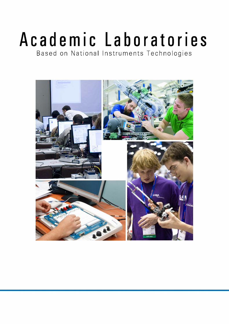
Enclosed you will find modern, state of the art education laboratories that are built based on LabVIEW and National Instruments’ Graphical Systems Design technologies.
With these labs the students get to learn the fundamental engineering disciplines in an interactive way using modern learning methodologies such as hands-on learning and project-based learning.
The labs are designed in a way that the students interact with the real world and bond with technology, and as such develop physical intuition and the understanding of real world constraints.
National Instruments Arabia
Beirut - Lebanon
Phone: +961-1-33 28 28
Fax: +961-1-33 43 00
E-mail: [email protected]
Bechara El Khoury Avenue, Bachoura Sector
Berytech Beirut Digital District Bldg, 5th floor
National Instruments Asia Minor Oclum Cihazlari A.S.Zincirlikuyu Mah. Kore Şehitleri Cad. Yonca Apt A Blok No.: 1 Kat: 2
Daire: 7 Zincilikuyu - 34394 ŞiŞli. Istanbul Turkey
Phone: +90-212-279 3031 Fax: +90-212-270 7974 E-mail : [email protected]

Electronics Engineering
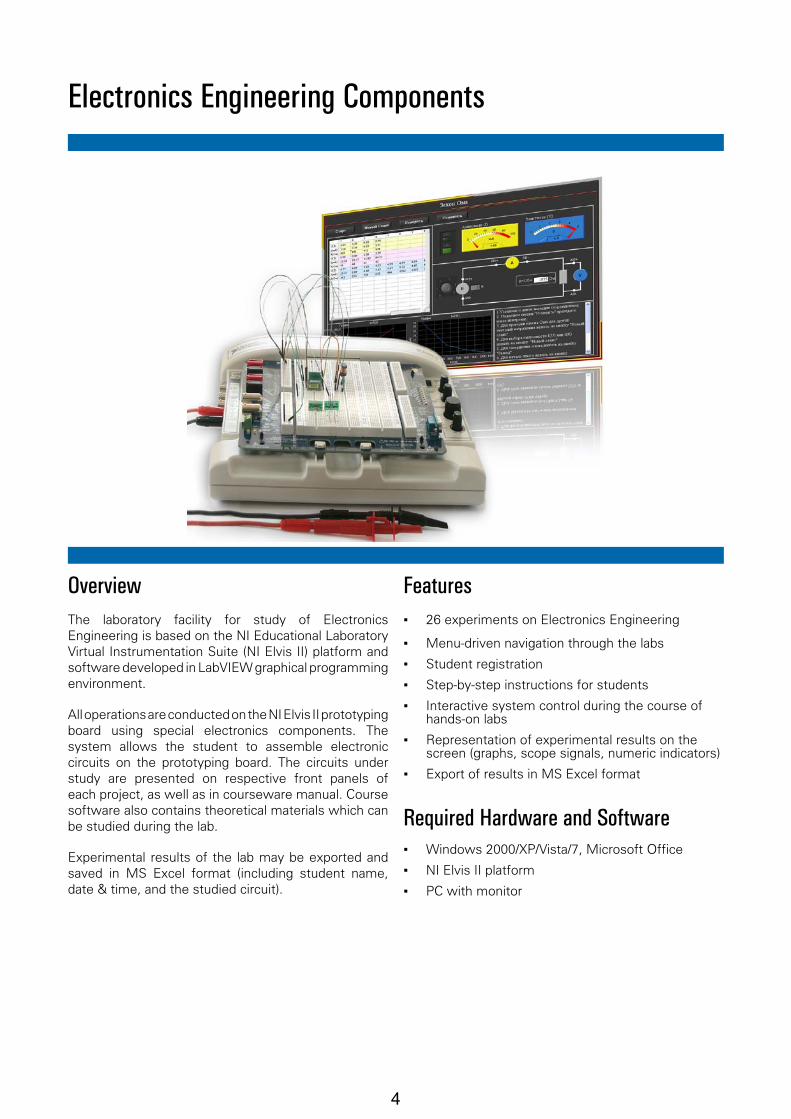
OverviewThe laboratory testbench for hands-on study of Electronics Engineering is based on the NI Educational Laboratory Virtual Instrumentation Suite (NI ELVIS II) platform used in conjunction with software developed in the LabVIEW graphical programming enviroment.
All hands-on operations are conducted on the «Electronics Engineering» board. The circuits to be assembled are presented on respective front panels of each hands-on project, as well as in courseware manual. Corresponding sections of the manual are included in lab software so that a student may refresh his memory on appropriate theoretical materials without interrupting practical work on the lab. Experimental results of the lab may be exported and saved in MS Excel format (including student name, date & time, and studied circuit).
Features ▪ 22 hands-on experiments in Electronics
Engineering
▪ Menu-driven navigation through the labs
▪ Student registration
▪ Interactive representation of circuits in each hands-on project
▪ Step-by-step instructions for students
▪ Interactive study guide for each experiment
▪ Preassembled board with electronic components
▪ Representation of experimental results on the screen (graphs, scope signals, numeric indicators)
▪ Export of results in MS Excel format
2
List of labsI. DC circuits1. Ohm’s law 2. Kirchhoff’s circuit laws3. Series connection of resistors4. Parallel connection of resistors5. Mixed parallel and series connection of resistors6. DC voltage source in electric circuits7. DC voltage source in electric circuits
II. AC circuits1. Resistance in AC circuits2. RL networks in AC circuits3. RC networks in AC circuits4. RLC networks in AC circuits5. Series connection of capacitors6. Parallel connection of capacitors7. Series connection of inductors8. Parallel connection of inductors9. Voltage resonance in AC circuits10. Current resonance in AC circuits11. Inductively coupled circuits12. Single-phase transformers
III. Transient processes1. Transient processes in linear RL circuits2. Transient processes in linear RC circuits
3. Transient processes in linear RLC circuits
Required Hardware and Software ▪ Windows XP, Microsoft Office
▪ LabVIEW 8.6.1or higher
▪ NI ELVIS II platform
▪ «22 experiments» board for NI ELVIS II with a set of connection wires
▪ Study guide and operations manual
▪ PC with monitor
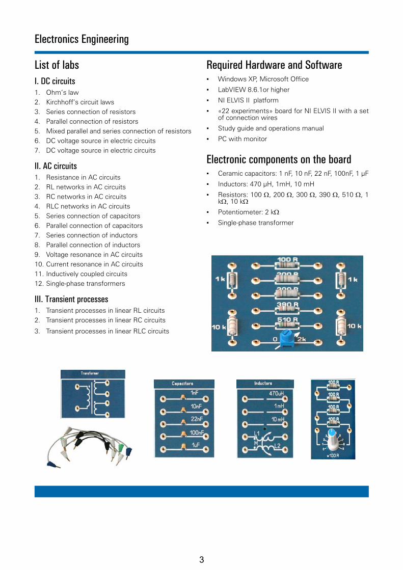
Electronic components on the board ▪ Ceramic capacitors: 1 nF, 10 nF, 22 nF, 100nF, 1 μF
▪ Inductors: 470 μH, 1mH, 10 mH
▪ Resistors: 100 Ω, 200 Ω, 300 Ω, 390 Ω, 510 Ω, 1 kΩ, 10 kΩ
▪ Potentiometer: 2 kΩ
▪ Single-phase transformer
Electronics Engineering
3
Electronics Engineering Components
OverviewThe laboratory facility for study of Electronics Engineering is based on the NI Educational Laboratory Virtual Instrumentation Suite (NI Elvis II) platform and software developed in LabVIEW graphical programming environment.
All operations are conducted on the NI Elvis II prototyping board using special electronics components. The system allows the student to assemble electronic circuits on the prototyping board. The circuits under study are presented on respective front panels of each project, as well as in courseware manual. Course software also contains theoretical materials which can be studied during the lab.
Experimental results of the lab may be exported and saved in MS Excel format (including student name, date & time, and the studied circuit).
Features ▪ 26 experiments on Electronics Engineering
▪ Menu-driven navigation through the labs
▪ Student registration
▪ Step-by-step instructions for students
▪ Interactive system control during the course of hands-on labs
▪ Representation of experimental results on the screen (graphs, scope signals, numeric indicators)
▪ Export of results in MS Excel format
Required Hardware and Software ▪ Windows 2000/XP/Vista/7, Microsoft Office
▪ NI Elvis II platform
▪ PC with monitor
4
List of labs
I. DC circuits1. Voltage source in electric circuits
2. Light sensitive resistors (photoresistors)
3. Kirchhoff’s circuit laws
4. Electric power, performance factor, source and load matching
5. Ohm’s law
6. Series connection of resistors
7. Parallel connection of resistors
8. Voltage dividers
9. Temperature sensitive resistors (thermistors)
10. Voltage dependent resistors (varistors)
11. Charging and discharging of capacitors
II. AC circuits1. Parallel connection of capacitors
2. Series connection of capacitors
3. AC circuits with capacitors
4. Parallel connection of inductors
5. Series connection of inductors
6. Voltage and current over inductors
7. Series connection of a resistor and an inductor
8. Series connection of a resistor and a capacitor
9. Parameters of AC voltage and current. Active power
10. Operation of transformers in open-circuit mode
11. Operation of transformers in short circuit mode
12. Operation of transformers with resistive load
13. Transient processes in RC networks
14. Transient processes in RL networks
15. Transient processes in RLC networks
Electronics Engineering Components
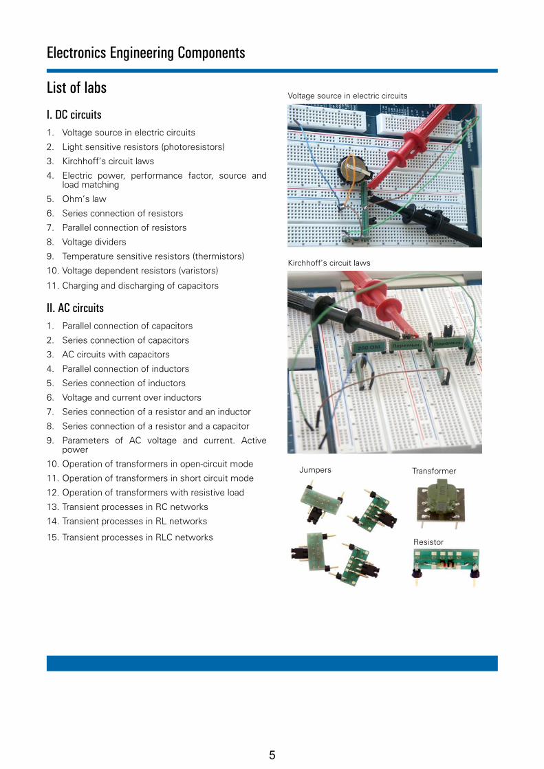
TransformerJumpers
Resistor
Voltage source in electric circuits
Kirchhoff’s circuit laws
5

Operational Amplifiers
OverviewThe laboratory facility has been developed for hands-on measurement of 5 basic parameters of Operational Amplifiers and study of 10 most common application circuits. It is based on the NI Educational Laboratory Virtual Instrumentation Suite (NI ELVIS II) platform and uses software developed with the LabVIEW graphical programming language.
All hands-on projects are conducted on the preassembled printed circuit board. The students can study the output signals of the circuits depending on the input stimulus. Course manual is embedded in lab software for easy access to ad-hoc theoretical materials during the lab. Experimental results, including student name, date & time, etc. may be exported and saved in MS Excel format.
These hands-on projects will help the students to gain a better understanding of the operating principles of operational amplifiers. Through the obtained experimental skills the students will be able to develop more efficient analog circuits.
Features ▪ 15 hands-on projects with Operational Amplifiers
▪ Menu-driven navigation through the labs
▪ Student registration
▪ Step-by-step instructions for students
▪ Interactive study guide for each experiment
▪ Grafical representation of experimental results
▪ Export results in MS Excel format
Required Hardware and Software ▪ Windows XP, Microsoft Office
▪ NI ELVIS II platform
▪ Operational Amplifiers board for NI ELVIS II
▪ PC with monitor
6
List of labs
I. Main Parameters of Operational Amplifiers1. Input impedance
2. DC offset and Bias Current
3. Output balancing
4. Gain and bandwidth
5. Common Mode Rejection Ratio (CMRR)
II. Application circuits based on Operational Amplifiers1. Phase shifter
2. Inverting amplifier
3. Non-Inverting amplifier
4. Addition and subtraction of analog signals
5. Active full-wave rectifier
6. Square- and triangular waveform generator
7. Comparator and Schmitt trigger
8. Differentiator
9. Integrator
10. Monostable (One-shot) multivibrator
Operational Amplifiers
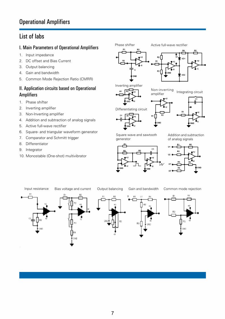
Phase shifter
Addition and subtraction of analog signals
Non-inverting amplifier Integrating circuit
Square wave and sawtooth generator
Active full-wave rectifier
Inverting amplifier
Differentiating circuit
Input resistance Bias voltage and current Output balancing Gain and bandwidth Common mode rejection
7

Power Electronics: Transformers, Rectifiers, Voltage Regulators
OverviewThe laboratory facility for hands-on experiments in Power Electronics (transformers, rectifiers and voltage regulators) is based on the NI Educational Laboratory Virtual Instrumentation Suite (NI ELVIS II) platform and uses software developed with the LabVIEW graphical programming language.
All hands-on operations are conducted on a preassembled printed circuit board with 14 different circuits. The students can study the operating principles of voltage and current regulators, DC-AC and DC-DC converters, measure the operational characteristics of AC voltage- and current generators. The students can also study the parameters of single-phase and triphase transformers and rectifiers, as well as diods, Zener diods and SCRs. Course manual is embedded in lab software for easy access to ad-hoc theoretical materials during the lab. Experimental results, including student name, date & time, etc. may be exported and saved in MS Excel format.
Features ▪ 19 experiments in Power Electronics
▪ Menu-driven navigation through the labs
▪ Student registration
▪ Step-by-step instructions for students
▪ Interactive study guide for each experiment
▪ Grafical representation of experimental results
▪ Export of results in MS Excel format
Required Hardware and Software ▪ Windows XP, Microsoft Office
▪ NI ELVIS II platform
▪ Power Electronics board for NI ELVIS II
▪ PC with monitor
8

List of labs1. Operational characteristics of DC voltage
generators
2. Operational characteristics of AC voltage generators
3. Operational characteristics of DC current generators
4. Operational characteristics of linear voltage regulators (current instability)
5. Operational characteristics of linear voltage regulators (voltage instability)
6. Operational characteristics of switching voltage regulators
7. Operational characteristics of switching voltage regulators with filter
8. Operational characteristics of SCRs
9. Operational characteristics of Zener diodes
10. Operational characteristics of single-phase transformers in idle running and short-circuit modes
11. Operational characteristics of single-phase transformers with active loads
12. Operational characteristics of single-phase rectifiers without a filter
13. Operational characteristics of a non-controlled single-phase rectifiers with a filter
14. Characteristics of three-phase networks with transformers (star/delta connection)
15. Characteristics of three-phase networks with transformers (star/star connection)
16. Operational characteristics of single-phase controlled rectifiers under active load
17. Operational characteristics of three-phase controlled rectifiers under active load
18. Operation of Three-Phase Circuits for Star Connection of Power Consumers
19. Operation of Three-Phase Circuits for Delta Connection of Power Consumers
Power Electronics: Transformers, Rectifiers, Voltage Regulators
Non-controlled rectifiers
Switching power supply
Single-phase transformer
Three-phase transformer
Controlled rectifiers
CONTROL
Filter
9

Micromotors and Automatic Motor Control
OverviewThe laboratory facility for hands-on study of Micromotors and Automatic Motor Control is based on the NI Educational Laboratory Virtual Instrumentation Suite (NI ELVIS II) platform and uses software developed with the LabVIEW graphical programming language.
All hands-on projects are implemented on the «Micromotors» printed circuit board with DC motors. The students can study the mechanical and static characteristics of DC motors in an open system with software-controlled power supply. Course manual is embedded in lab software for easy access to ad-hoc theoretical materials during the lab. Experimental results of the lab, including student name, date & time, etc. may be exported and saved in MS Excel format.
Features ▪ 10 hands-on projects with DC motors
▪ Menu-driven navigation through the labs
▪ Student registration
▪ Step-by-step instructions for students
▪ Interactive study guide for each experiment
▪ Grafical representation of experimental results
▪ Export results in MS Excel format
Required Hardware and Software ▪ Windows 2000 / XP / Vista / 7, Microsoft Office,
Adobe Acrobat Reader 9
▪ NI ELVIS II platform
▪ Microdrives board for NI Elvis II
▪ PC with monitor
▪ Microdrives Hands-on Software (included)
10
Micromotors and Automatic Motor Control
List of labsSTATIC PARAMETERS OF THE SYSTEM
1. Armature resistance
2. Electromechanical conversion factor
3. Mechanical characteristics of DC motors
4. Operational characteristics of DC motors
5. Static speed-torque characteristics of a single-loop control system with regulators
DYNAMIC PARAMETERS OF THE SYSTEM
6. Dynamic characteristics of an open-loop DC motor control system
DYNAMIC OF SYSTEMS WITH REGULATORS (Hardware implementation)
7. Dynamic characteristics of a DC motor single-loop control system
8. Dynamic characteristics of a DC motor double-loop control system
9. Dynamic characteristics of a DC motor single-loop angular position control system
10. Dynamic characteristics of a DC motor double-loop angular position control system
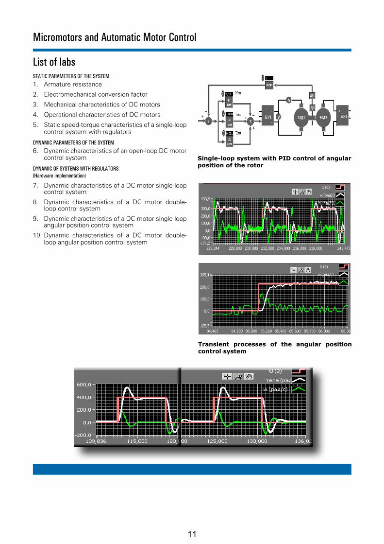
Single-loop system with PID control of angular position of the rotor
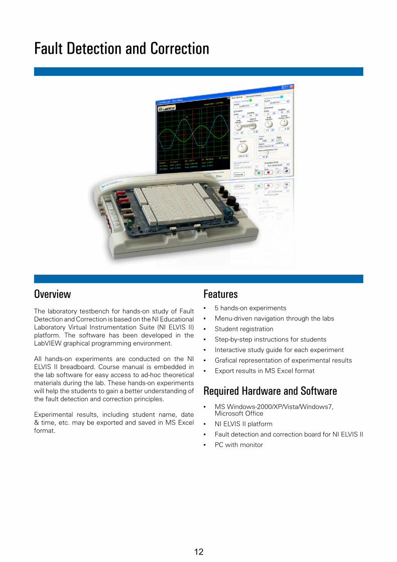
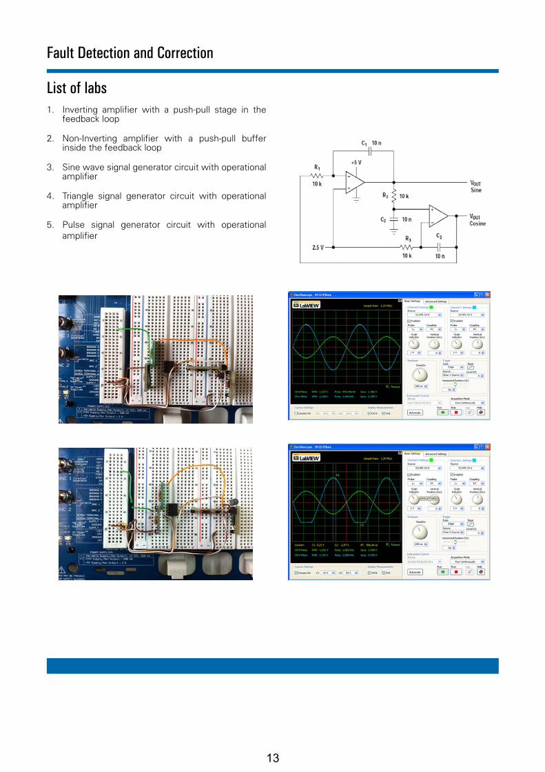
Transient processes of the angular position control system
11
Fault Detection and Correction
OverviewThe laboratory testbench for hands-on study of Fault Detection and Correction is based on the NI Educational Laboratory Virtual Instrumentation Suite (NI ELVIS II) platform. The software has been developed in the LabVIEW graphical programming environment.
All hands-on experiments are conducted on the NI ELVIS II breadboard. Course manual is embedded in the lab software for easy access to ad-hoc theoretical materials during the lab. These hands-on experiments will help the students to gain a better understanding of the fault detection and correction principles.
Experimental results, including student name, date & time, etc. may be exported and saved in MS Excel format.
Features ▪ 5 hands-on experiments
▪ Menu-driven navigation through the labs
▪ Student registration
▪ Step-by-step instructions for students
▪ Interactive study guide for each experiment
▪ Grafical representation of experimental results
▪ Export results in MS Excel format
Required Hardware and Software ▪ MS Windows-2000/XP/Vista/Windows7,
Microsoft Office
▪ NI ELVIS II platform
▪ Fault detection and correction board for NI ELVIS II
▪ PC with monitor
12
List of labs1. Inverting amplifier with a push-pull stage in the
feedback loop
2. Non-Inverting amplifier with a push-pull buffer inside the feedback loop
3. Sine wave signal generator circuit with operational amplifier
4. Triangle signal generator circuit with operational amplifier
5. Pulse signal generator circuit with operational amplifier
Fault Detection and Correction
13

Metering Instruments Calibration
OverviewThe laboratory testbench for hands-on study of Digital Electrical Metering Instruments Calibration is based on the NI Educational Laboratory Virtual Instrumentation Suite (NI ELVIS II) platform, which includes a built-in oscilloscope and a digital multimeter. The software has been developed in the LabVIEW graphical programming environment.
All hands-on experiments are conducted on the NI Elvis II breadboard. Course manual is embedded in the lab software for easy access to ad-hoc theoretical materials during the lab. These hands-on experiments will help the students to gain a better understanding of the calibration principles.
Experimental results, including student name, date & time, etc. may be exported and saved in MS Excel format.
Features ▪ 6 hands-on experiments
▪ Menu-driven navigation through the labs
▪ Student registration
▪ Step-by-step instructions for students
▪ Interactive study guide for each experiment
▪ Grafical representation of experimental results
▪ Export results in MS Excel format
Required Hardware and Software ▪ MS Windows-2000/XP/Vista/Windows7,
Microsoft Office
▪ NI ELVIS II platform
▪ Calibration board for NI ELVIS II
▪ PC with monitor
14

List of labs1. Calibration and utilization of an oscilloscope
2. Characterization of frequency-response of the Y-channel of an oscilloscope
3. Calibration of digital multimeter in DC voltage measurement mode
4. Calibration of digital multimeter in DC current measurement mode
5. Determination of frequency error of a digital multimeter in AC voltage measurement mode
6. Determination of frequency error of a digital multimeter in AC current measurement mode
Metering Instruments Calibration
15
Compact RIO Others
NI Compatible Platforms1
NI: National Instruments
2
1.
2. Please check with us about compatibility of other NI Platforms
Software
User friendly with easy to use interface
Developed using NI LabVIEW package
Built-in safety features & limitations, and designed for students’ use
Features
Computer based Temperature Measurement Trainer used to teach temperature sensing tech-nologies
Comprises all required sensors to measure temperature in a chamber
For use with National Instruments Data Acquisition & Control hardware
Curriculum Coverage
Thermocouple CharacteristicsRTD Characteristics Thermistor Characteristics Comparison between Temperature Sensing Devices
Description
TMT001 is a bench-mount trainer that is used to teach students how to measure temperature using different types of sensing devices; Thermocouple (TC), Resistive Temperature Device (RTD) and Thermistor.
Developed for use with a wide variety of National Instruments data acquisition and control platforms - easy-to-use, highly expandable programmable automation controllers, intelligent communication interfaces, and rugged I/O mod-ules.
The curriculum covered includes understanding the characteristics of the different temperature measuring devices and comparing between their different behaviors and characteristics.
Components
Thermocouple RTD Thermistor Heater Fan Temperature Controller
Temperature Measurement Trainer
Ordering InformationTemperature Measurement Trainer
TMT001 - A - B
For complete product specifications, pricing, and information: e-mail: [email protected] / website: www.ti-acad.jo
Power
1... 110 VAC2... 220 VAC
TMT001-04 Exp. 2 RTD Characteristics
*Purchase NI Hardware Separately
NI* Platform
2... cRIO
Required NI Modules
cRIO: NI-9219, NI-9474
16

Temperature Measurement Trainer
Technical Specifications
Temperature Measurement Trainer Specifications:
Dimensions (LxWxH): 30 x 20 x 25 mm
Dimensions:
Maximum Allowable Temperature: 90 °C
Safety Considerations:
J-Type
Thermocouple:
Thermistor:
Resistance @ 25 °C 6000 ohms
PT100
RTD:
Class BProbe Length: 10 cm
Mercury
Glass Thermometer:
0-200 °C
Dimensions: 15 x 10 cm
Heater:
Power: 150 Watt220 Volt 50 Hz
Set point: 30 °C
Temperature Controller:
On/off control
For complete product specifications, pricing, and information: e-mail: [email protected] / website: www.ti-acad.jo
Probe Length: 10 cm
Probe Length: 10 cm
17

PXIeCompact RIO Others
NI Compatible Platforms1
NI: National Instruments
2
1.
2. Please check with us about compatibility of other NI Platforms
Software
User friendly with easy to use interface
Developed using NI LabVIEW package
Built-in safety features & limitations, and designed for students’ use
Features
Computer based Level & Pressure Measurement Trainer used to teach level and pressure sensing technologies
Includes all required sensors to measure level and pressure
For use with National Instruments Data Acquisition & Control hardware
Curriculum Coverage
Capacitance Level Meter CharacteristicsUltrasonic Level Meter CharacteristicsPiezoresistive Sensor CharacteristicsCapacitance Change Sensor Characteristics (with option)
Description
LPMT001 is a bench-mount trainer that is used to teach students how to measure level and pressure using different types of measuring devices; Capacitance Level Meter, Ultrasonic Level Meter, Piezoresistive Pressure Sensor and Capacitance Change Pressure Sensor (option).
Developed for use with a wide variety of National Instruments data acquisition and control platforms - easy-to-use, highly expandable programmable automation controllers, intelligent communication interfaces, and rugged I/O mod-ules. These industrial I/O modules filter, calibrate, and scale raw sensor signals to engineering units and perform self-diagnostics to look for problems.
The curriculum covered includes understanding the characteristics of the different level measuring devices and com-paring between their different behaviors and characteristics.
Components
PumpFlow Control ValvePiezoresistive Sensor Ultrasonic Level MeterCapacitance LevelCapacitance Change Pressure Sensor (Option)
Level & Pressure Measurement Trainer
Ordering InformationLevel & Pressure Measurement Trainer
LPMT001 - A - B - C
NI* Platform
1... PXIe2... cRIO
Power
1... 110 VAC2... 220 VAC
*Purchase NI Hardware Separately
Options
0... No Option1... Capacitance Change Pressure Sensor
Required NI Modules
PXIe: PXI-6236, PXIe-6251, PXI-6514 cRIO: NI-9215, NI-9203, NI-9474, NI-9263
18

Sensors Lab - Technological Parameters Registration
OverviewThe laboratory stand of «Sensors Lab - Technological Parameters Registration» is designed for students of higher, secondary and primary professional educational institution.
The stand is based on unified shaped platform which consists of an aluminum mounting plate with required marking and mounting holes. The stand is packaged with specialized software, various types of sensors and National Instruments data acquisition system.
The stand allows to measure the signals from various sensors and is able to be connected to a PC via USB 2.0 interface.
List of labs1. The study of thermocouple
2. The study of thermistor
3. The study of pressure sensors
4. The study of force sensor
5. The study of acceleration sensor
6. The study of quadrature encoder
7. The study of servomotor and quadrature encoder
Packaging ▪ Unified platform, subassemblies, drivers,
mounting holes
▪ A set of sensors, measuring and performing devices and modules
▪ NI cDAQ based data acquisition system
▪ PC or Notebook
▪ User manual and installed software
19

PXIeCompact RIO Others
NI Compatible Platforms1
NI: National Instruments
2
1.
2. Please check with us about compatibility of other NI Platforms
Software
User friendly with easy to use interface
Developed using NI LabVIEW package
Built-in safety features & limitations
Features
Asynchronous Motor Setup demonstrates the electrical and mechanical characteristics of an asynchronous motor.
Comprises all required hardware to observe the characteristics of an asynchronous motor
For use with National Instruments Data Acquisition & Control hardware
Curriculum Coverage
Description
The Asynchronous Motor Setup demonstrates the electrical and mechanical characteristics of an asynchronous motor. The software measures the voltage, current, speed and torque, and uses these measurements to calculate the following parameters; RMS and average values of the voltage & the current), Frequency, Electrical Power, Mechani-cal Power, Motor Efficiency, Losses, Equivalent Circuit Parameters and Current and Voltage THD’s.
The curriculum covered includes; Voltage & Current Waveforms, Phasor Diagram, Frequency Domain Analysis, Torque-Speed Characteristics, Power & Efficiency...etc.
Components
1.1 kW MotorPower SupplyStarterPowder BrakeVariable Frequency Driver Current TransformerTorquemeter
1.1 kW Asynchronous Motor Setup System
Ordering InformationAsynchronous Motor Setup System
AMS001 - 1.1 - A - B
*Purchase NI Hardware Separately
NI* Platform
1... PXIe2... cRIO
Power
1...3x380 + N, 50/60 Hz
Motor ConnectionEquivalent Circuit ParametersVoltage & Current Waveforms Phasor Diagram Frequency Domain AnalysisTorque-Speed CharacteristicsPower & Efficiency Motor Torque
MeterBrake
3Ø
Required NI Modules
PXIe: PXIe-6251, PXIe-4300, PXIe-4330cRIO: NI-9225, NI-9239, NI-9263, NI-9421, NI-9474
20

1.1 kW Asynchronous Motor Setup System
Technical Specifications
Power: 1.1 KWVoltage: 220/380 V ∆/YCurrent: 4.7/2.7 A ∆/YSpeed: 2800 rpm, 50 Hz
Squirrel Cage Three-Phase Asynchronous Motor:
Variable AC: 3x0-480 V, 5 A (programmable) 3x0-240 V, 10 A (programmable)
Fixed AC: 3X380 V + N, 16 AStandard Fixed AC: 220 V, 10 A
Variable DC: 0-209 V, 12 A (programmable) 0-225 V, 1 A
Fixed DC: 220 V, 10 APower Supply: 3x380 V + N, 50/60 Hz
Motor-driven power supply:
For the three-phase squirrl-cage induction motor
Star/Delta Starter:
Maximum Supply Voltage:20 V dcMaximum Speed:4000 rpmMaximum Torque:20 Nm
Powder Brake:
Input: 3-phOutput 3-ph 5.5 kW
Variable Frequency Drive:
0.5% LinearitySplit-coreAC input 50 ampsAC output 5V
Split-Core Current Transformer:
Full Scale Torque Rating: 500 lbf-in (56.5 Nm)Overload Rating: 1000 lbf-inSpeed Rating: 7000 rpmPower Supply Requirements: 10 to 15 VDCOutput Signal, Speed: 60 pulses per revolutionInstalled Options: Zero velocity speed pickup (code Z)
Compact Digital Torquemeter:
21
Asynchronous Motor With Squirrel Cage
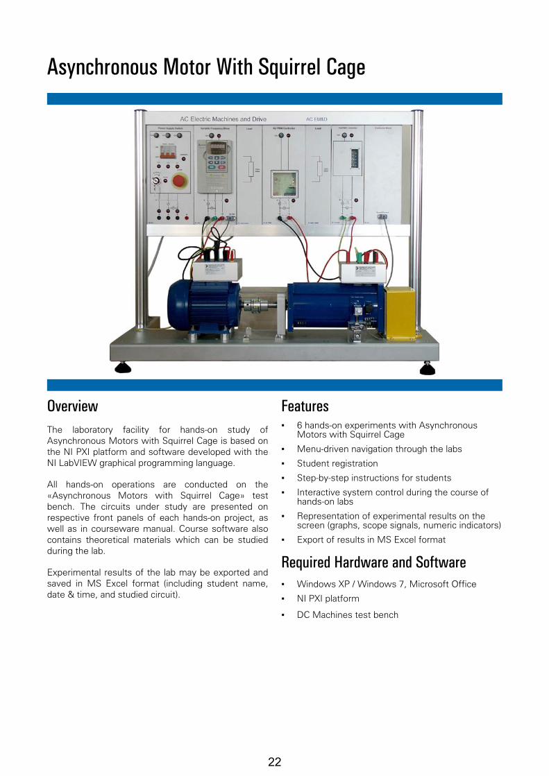
OverviewThe laboratory facility for hands-on study of Asynchronous Motors with Squirrel Cage is based on the NI PXI platform and software developed with the NI LabVIEW graphical programming language.
All hands-on operations are conducted on the «Asynchronous Motors with Squirrel Cage» test bench. The circuits under study are presented on respective front panels of each hands-on project, as well as in courseware manual. Course software also contains theoretical materials which can be studied during the lab.
Experimental results of the lab may be exported and saved in MS Excel format (including student name, date & time, and studied circuit).
Features ▪ 6 hands-on experiments with Asynchronous
Motors with Squirrel Cage
▪ Menu-driven navigation through the labs
▪ Student registration
▪ Step-by-step instructions for students
▪ Interactive system control during the course of hands-on labs
▪ Representation of experimental results on the screen (graphs, scope signals, numeric indicators)
▪ Export of results in MS Excel format
Required Hardware and Software ▪ Windows XP / Windows 7, Microsoft Office
▪ NI PXI platform
▪ DC Machines test bench
22
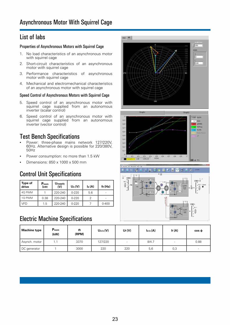
List of labsProperties of Asynchronous Motors with Squirrel Cage
1. No load characteristics of an asynchronous motor with squirrel cage
2. Short-circuit characteristics of an asynchronous motor with squirrel cage
3. Performance characteristics of asynchronous motor with squirrel cage
4. Mechanical and electromechanical characteristics of an asynchronous motor with squirrel cage
Speed Control of Asynchronous Motors with Squirrel Cage
5. Speed control of an asynchronous motor with squirrel cage supplied from an autonomous inverter (scalar control)
6. Speed control of an asynchronous motor with squirrel cage supplied from an autonomous inverter (vector control)
Test Bench Specifications ▪ Power: three-phase mains network 127/220V,
60Hz. Alternative design is possible for 220/380V, 50Hz
▪ Power consumption: no more than 1.5 kW
▪ Dimensions: 850 х 1000 х 500 mm
Control Unit SpecificationsType of drive
Рnom (kW)
Usupply (V) Ua (V) Ia (A) f0 (Hz)
4Q PWM 1 220-240 0-220 5.6 -
1Q PWM 0.38 220-240 0-220 2 -
VFD 1.5 220-240 0-220 7 0-400
Electric Machine Specifications
Machine type Рnom
(kW)n
(RPM)Us/a (V) Uf (V) Is/a (А) If (А) cos φ
Asynch. motor 1.1 3370 127/220 - 8/4.7 - 0.88
DC generator 1 3000 220 220 5,6 0,3 -
Asynchronous Motor With Squirrel Cage
23

DC Machines
OverviewThe laboratory facility for hands-on study of DC Machines is based on the NI PXI platform and software developed with the NI LabVIEW graphical programming language.
All hands-on operations are conducted on the «DC Machines» test bench. The circuits under study are presented on respective front panels of each hands-on project, as well as in courseware manual. Course software also contains theoretical materials which can be studied during the lab.
Experimental results of the lab may be exported and saved in MS Excel format (including student name, date & time, and studied circuit).
Features ▪ 10 hands-on experiments with DC machines
▪ Menu-driven navigation through the labs
▪ Student registration
▪ Step-by-step instructions for students
▪ Interactive system control during the course of hands-on labs
▪ Representation of experimental results on the screen (graphs, scope signals, numeric indicators)
▪ Export of results in MS Excel format
Required Hardware and Software ▪ Windows XP / Windows 7, Microsoft Office
▪ NI PXI platform
▪ DC Machines test bench
24
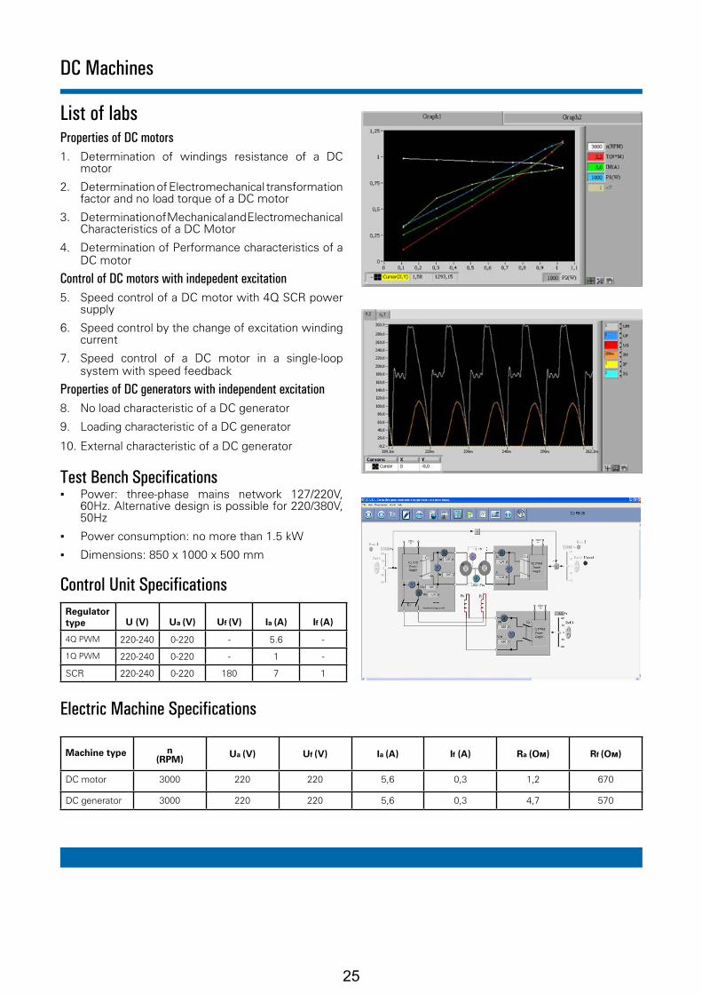
List of labsProperties of DC motors1. Determination of windings resistance of a DC
motor
2. Determination of Electromechanical transformation factor and no load torque of a DC motor
3. Determination of Mechanical and Electromechanical Characteristics of a DC Motor
4. Determination of Performance characteristics of a DC motor
Control of DC motors with indepedent excitation5. Speed control of a DC motor with 4Q SCR power
supply
6. Speed control by the change of excitation winding current
7. Speed control of a DC motor in a single-loop system with speed feedback
Properties of DC generators with independent excitation8. No load characteristic of a DC generator
9. Loading characteristic of a DC generator
10. External characteristic of a DC generator
Test Bench Specifications ▪ Power: three-phase mains network 127/220V,
60Hz. Alternative design is possible for 220/380V, 50Hz
▪ Power consumption: no more than 1.5 kW
▪ Dimensions: 850 х 1000 х 500 mm
Control Unit SpecificationsRegulator type U (V) Ua (V) Uf (V) Ia (A) If (A)
4Q PWM 220-240 0-220 - 5.6 -
1Q PWM 220-240 0-220 - 1 -
SCR 220-240 0-220 180 7 1
Electric Machine Specifications
Machine type n (RPM)
Ua (V) Uf (V) Ia (А) If (А) Ra (Ом) Rf (Ом)
DC motor 3000 220 220 5,6 0,3 1,2 670
DC generator 3000 220 220 5,6 0,3 4,7 570
DC Machines
25
PXIeCompact RIO Others
NI Compatible Platforms1
NI: National Instruments
2
1.
2. Please check with us about compatibility of other NI Platforms
Software
User friendly with easy to use interface
Developed using NI LabVIEW package
Built-in safety features & limitations
Features
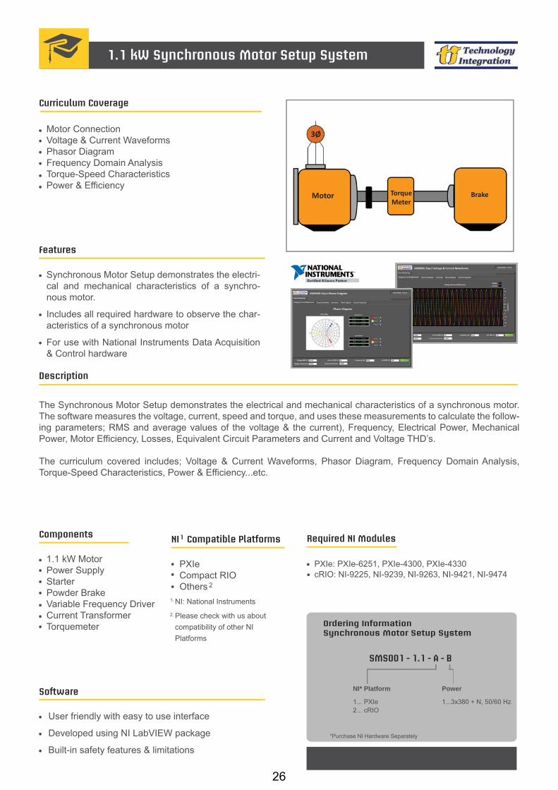
Synchronous Motor Setup demonstrates the electri-cal and mechanical characteristics of a synchro-nous motor.
Includes all required hardware to observe the char-acteristics of a synchronous motor
For use with National Instruments Data Acquisition & Control hardware
Curriculum Coverage
Description
The Synchronous Motor Setup demonstrates the electrical and mechanical characteristics of a synchronous motor. The software measures the voltage, current, speed and torque, and uses these measurements to calculate the follow-ing parameters; RMS and average values of the voltage & the current), Frequency, Electrical Power, Mechanical Power, Motor Efficiency, Losses, Equivalent Circuit Parameters and Current and Voltage THD’s.
The curriculum covered includes; Voltage & Current Waveforms, Phasor Diagram, Frequency Domain Analysis, Torque-Speed Characteristics, Power & Efficiency...etc.
Components
1.1 kW MotorPower SupplyStarterPowder BrakeVariable Frequency Driver Current TransformerTorquemeter
1.1 kW Synchronous Motor Setup System
Ordering InformationSynchronous Motor Setup System
SMS001 - 1.1 - A - B
*Purchase NI Hardware Separately
NI* Platform
1... PXIe2... cRIO
Motor ConnectionVoltage & Current Waveforms Phasor Diagram Frequency Domain AnalysisTorque-Speed CharacteristicsPower & Efficiency
Motor TorqueMeter
Brake
3Ø
Required NI Modules
PXIe: PXIe-6251, PXIe-4300, PXIe-4330cRIO: NI-9225, NI-9239, NI-9263, NI-9421, NI-9474
Power
1...3x380 + N, 50/60 Hz
26

Technical Specifications
Power: 1.1 KWVoltage: 220/380 V ∆/YCurrent: 2.9/1.7 A ∆/YSpeed: 3000 rpm
Synchronous Motor:
Variable AC: 3x0-480 V, 5 A (programmable) 3x0-240 V, 10 A (programmable)
Fixed AC: 3X380 V + N, 16 AStandard Fixed AC: 220 V, 10 A
Variable DC: 0-209 V, 12 A (programmable) 0-225 V, 1 A
Fixed DC: 220 V, 10 APower Supply: 3x380 V + N, 50/60 Hz
Motor-driven power supply:
Maximum Supply Voltage: 20 V dcMaximum Speed: 4000 rpmMaximum Torque: 20 Nm
Powder Brake:
Input: 3-phOutput 3-ph 5.5 kW
Variable Frequency Drive:
0.5% LinearitySplit-coreAC input 50 ampsAC output 5V
Split-Core Current Transformer:
Full Scale Torque Rating: 500 lbf-in (56.5 Nm)Overload Rating: 1000 lbf-inSpeed Rating: 7000 rpmPower Supply Requirements: 10 to 15 VDCOutput Signal, Speed: 60 pulses per revolutionInstalled Options: Zero velocity speed pickup (code Z)
Compact Digital Torquemeter:
1.1 kW Synchronous Motor Setup System
27
Synchronous Machines
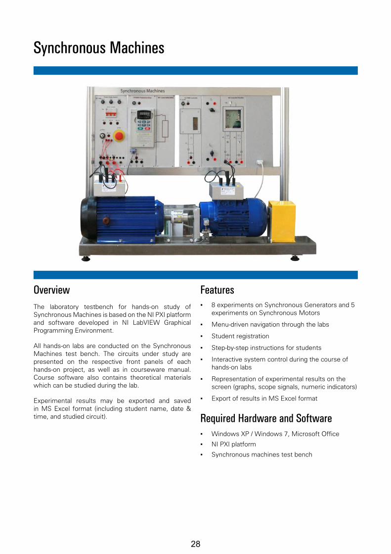
OverviewThe laboratory testbench for hands-on study of Synchronous Machines is based on the NI PXI platform and software developed in NI LabVIEW Graphical Programming Environment.
All hands-on labs are conducted on the Synchronous Machines test bench. The circuits under study are presented on the respective front panels of each hands-on project, as well as in courseware manual. Course software also contains theoretical materials which can be studied during the lab.
Experimental results may be exported and saved in MS Excel format (including student name, date & time, and studied circuit).
Features ▪ 8 experiments on Synchronous Generators and 5
experiments on Synchronous Motors
▪ Menu-driven navigation through the labs
▪ Student registration
▪ Step-by-step instructions for students
▪ Interactive system control during the course of hands-on labs
▪ Representation of experimental results on the screen (graphs, scope signals, numeric indicators)
▪ Export of results in MS Excel format
Required Hardware and Software ▪ Windows XP / Windows 7, Microsoft Office
▪ NI PXI platform
▪ Synchronous machines test bench
28
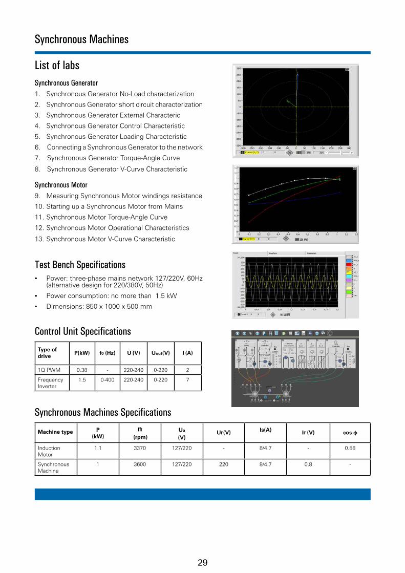
List of labsSynchronous Generator1. Synchronous Generator No-Load characterization
2. Synchronous Generator short circuit characterization
3. Synchronous Generator External Characteric
4. Synchronous Generator Control Characteristic
5. Synchronous Generator Loading Characteristic
6. Connecting a Synchronous Generator to the network
7. Synchronous Generator Torque-Angle Curve
8. Synchronous Generator V-Curve Characteristic
Synchronous Motor9. Measuring Synchronous Motor windings resistance
10. Starting up a Synchronous Motor from Mains
11. Synchronous Motor Torque-Angle Curve
12. Synchronous Motor Operational Characteristics
13. Synchronous Motor V-Curve Characteristic
Test Bench Specifications ▪ Power: three-phase mains network 127/220V, 60Hz
(alternative design for 220/380V, 50Hz)
▪ Power consumption: no more than 1.5 kW
▪ Dimensions: 850 х 1000 х 500 mm
Control Unit Specifications
Type of drive Р(kW) f0 (Hz) U (V) Uout(V) I (A)
1Q PWM 0.38 - 220-240 0-220 2
Frequency Inverter
1.5 0-400 220-240 0-220 7
Synchronous Machines Specifications
Machine type P (kW)
n (rpm)
Ua
(V)UF(V) IS(A) IF (V) cos φ
Induction Motor
1.1 3370 127/220 - 8/4.7 - 0.88
Synchronous Machine
1 3600 127/220 220 8/4.7 0.8 -
Synchronous Machines
29

Transformers
OverviewThe laboratory testbench for hands-on study of Transformers is based on the NI PXI platform and software developed in NI LabVIEW graphical programming environment.
All hands-on operations are conducted on the Transformers test bench. The circuits under study are presented on respective front panel of each hands-on project, as well as in courseware manual. Course software also contains theoretical materials which can be studied during the lab.
Experimental results of the lab may be exported and saved in MS Excel format (including student name, date & time, and studied circuit).
Features ▪ 6 hands-on experiments with transformers
▪ Menu-driven navigation through the labs
▪ Student registration
▪ Step-by-step instructions for students
▪ Interactive system control during the course of hands-on labs
▪ Representation of experimental results on the screen (graphs, scope signals, numeric indicators)
▪ Export of results in MS Excel format
Required Hardware and Software ▪ Windows XP / Windows 7, Microsoft Office
▪ NI PXI platform
▪ Transformers test bench
30

List of labs
1. No-Load mode and determining the transformer ratio
2. Short-circuit mode
3. External characteristics of a single phase transformer
4. Parallel operation of single phase transformers
5. Marking of tri-phase transformer windings
6. Operation of a tri-phase transformer with unbalanced load
Test Bench Specifications ▪ Power: three-phase mains network 127/220V, 60Hz
(alternative design for 220/380V, 50Hz)
▪ Power consumption: no more than 1 kW
▪ Dimensions: 850 х 1000 х 500 mm
Control Unit Specifications
Type of unitР (kW) f (Hz) U (V) Uout(V) I (A)
ON/OFF the stand and uncontrolled three-phase power supply
- 50/60 127-220 127-220 10
AC voltage regulator based on single-phase autotransformer
0.62 50/60 220 0-250 2.8
Variable resistive load
0.5 - 220 - 2.2
Transformer Specifications
Transformer type
P (kW) f (Hz) Uin (V) Uout(V) Iin (A) Iout (A)
Single-phase transformer
0.2 60 220 127 0.9 1.57
Three-phase transformer
0.2 60 220 127 0.53 0.91
Transformers
31

Electric Drives and Machines
OverviewThe laboratory testbench for hands-on study of Electric Drives and Machines is based on the NI PXI platform and software developed in NI LabVIEW Graphical Programming Environment.
All hands-on labs are conducted on the Electric Drives and Machines test bench. The circuits under study are presented on the respective front panels of each hands-on project, as well as in courseware manual. Course software also contains theoretical materials which can be studied during the lab.
Experimental results may be exported and saved in MS Excel format (including student name, date & time, and studied circuit).
Features ▪ 26 experiments on Electric Drives and Machines
▪ Menu-driven navigation through the labs
▪ Student registration
▪ Step-by-step instructions for students
▪ Interactive system control during the course of hands-on labs
▪ Representation of experimental results on the screen (graphs, scope signals, numeric indicators)
▪ Export of results in MS Excel format
Required Hardware and Software ▪ Windows XP / Windows 7, Microsoft Office
▪ NI PXI platform
▪ Electric Drives and Machines test bench
32

List of labsElectric Drives1. Mechanical characteristics of a separate excitation DC
motor2. Mechanical characteristics of a separate excitation DC
motor connected to a nonreversible silicon-controlled rectifier
3. Starting-up a separate excitation DC motor connected to a controlled rectifier
4. Mechanical characteristics of a cage-rotor inductance motor connected to AC mains supply
5. Mechanical characteristics of a cage-rotor inductance motor connected to a frequency inverter
6. Mechanical characteristics of a cage-rotor inductance motor connected to a silicon-controlled voltage regulator
7. Starting-up a cage-rotor inductance motor connected to a variety of power sources
8. Mechanical and angular characteristics of a synchronous motor connected to AC mains supply
9. Starting-up a synchronous motor connected to AC mains supply
10. Static characterization of a system consisting of a Nonreversible SCR rectifier and an Independent Excitation DC motor with rotary speed feedback
Electric Machines11. Operational characterization of a DC motor with separate
excitation12. Operational characterization of a cage-rotor inductance
motor13. Characterization of a cage-rotor inductance motor in
short-circuit operation mode14. Operational characterization of a cage-rotor inductance
motor15. Operational characterization of a synchronous motor16. V-curve characterization of a synchronous motor17. No-load characterization of a three-phase synchronous
generator18. External characterization of a three-phase synchronous
generator (active load)19. Characterization of regulation curve of a three-phase
synchronous generator (active load)20. Load characterization of a three-phase synchronous
generator (active load)21. Connecting a three-phase synchronous generator to
the network using the ideal synchronization and self-synchronization methods
22. Angular characterization of a three-phase synchronous generator
23. V-curve characterization of a three-phase synchronous generator
Transformers24. No-load characterization of a three-phase transformer25. Short-circuit characterization of a three-phase transformer26. External characterization of a three-phase transformer
(active load)
Test Bench Specifications
▪ Power: three-phase mains network 127/220V, 60Hz (alternative design for 220/380V, 50Hz)
▪ Power consumption: no more than 1.5 kW
▪ Dimensions: 850 х 1000 х 500 mm
Electric Drives and Machines
33

Ordering InformationForce & Strain Measurement Trainer
FSMT001 - A - B - C
NI* Platform
1... PXIe2... cRIO
Power
1... 110 VAC2... 220 VAC
Options
0... No Option1... With LVDT Option
*Purchase NI Hardware Separately
Compact RIOOthers
NI Compatible Platforms1
NI: National Instruments
2
1.
2. Please check with us about compatibility of other NI Platforms
Features
Computer based Force & Strain Measurement Trainer
Includes all required weight specimens and sensors to measure force & strain
For use with National Instruments Data Acquisition & Control hardware
Software
User friendly with easy to use interface
Developed using NI LabVIEW package
Built-in safety features & limitations, and designed for students’ use
Curriculum Coverage
Acquiring Physical PhenomenaBending Strain & StressTorsional Strain & StressTensile Strain & Stress
Description
Strain and Force Measurement Trainer is an ideal setup for introducing strain gauge measurement to students. It introduces the operation principle of strain gauges and the conversion methods between electronic raw data and strain and force.
Developed for use with a wide variety of National Instruments data acquisition platforms - easy-to-use, highly expand-able programmable automation controllers, intelligent communication interfaces, and rugged I/O modules. These industrial I/O modules filter, calibrate, and scale raw sensor signals to engineering units and perform self-diagnostics to look for problems.
Students will learn how to connect bridge type sensors, strain in bending, torsion, and tension, force measurement using load cells and measurements using the LVDT, …etc.
Components
Strain Gauge Load CellWeights LVDT (Option)Aluminum Shaft (SP)Dim (mm): Dia10, L 350 Aluminum Beam (SP)Dim (mm): L 340, W25, T3Aluminum Plate (SP)Dim (mm): L 120, W25, T2
Force & Strain Measurement Trainer
For complete product specifications, pricing, and information: e-mail: [email protected] / website: www.ti-acad.jo
Required NI Modules
PXIe : PXIe-43303
cRIO : NI-9237PXIe: for LVDT option, add PXI-62513.
4
cRIO: for LVDT option, add NI-92154.
34
Force & Strain Measurement Trainer
Technical Specifications
Force & Strain Measurement Trainer Specifications:
Dimensions (LxWxH): 950 x 900 x 50 mm
Dimensions & Volume:
Shaft Material: Aluminum Shaft Dimensions: 350 x 10 mmStrain Gauges: 350 Ω, 4 wires, qty. 2Maximum Load: 5.0 Kg
Torsion:
Beam Material: Aluminum Dimensions: 340 x 25 x 3 mmStrain Gauges: 350 Ω, 2 wires, qty. 4Maximum Load: 0.5 Kg
Bending:
Specimen Material: Aluminum Dimensions: 10 x 125 x 3 mmStrain Gauges: 350 Ω, 4 wires, qty. 2Maximum Load: 5.0 Kg
Tension:
Linearity: <0.2% FSO Excitation: 3 ± 1 VrmsExcitation Frequency: 5 ± 0.5 kHzProtection Rating: IP67
LVDT:
Rated output: 1.0 ± 0.1 mV/V Zero balance: 0 ±0.05 mV/VExcitation:10 VInput Resistance: 400 ΩOutput Resistance: 350 ΩMaterial: Anodized AluminumMaximum load: 3 Kg
Load Cell:
35

Strength of Materials
OverviewThe laboratory facility for hands-on study of Strengths of Materials is based on the NI PXI Express programmable data acquisition and control platform and software developed in LabVIEW graphical programming language.
Tensions and deformations appearing in the studied objects are measured with surface-mount strain gauge probes. In the process of deformation the students can measure various mechanical parameters of experimental objects which are made from different materials and have various shapes.
The software is menu-oriented and allows the student to choose from 16 hands-on operations. Corresponding sections of the manual are included in lab software so that a student may refresh his memory on appropriate theoretical materials without interrupting practical work on the lab. Experimental results of the lab may be exported and saved in MS Excel format (including student name, date & time, and studied circuit)
Features ▪ 16 hands-on projects in Strengths of Materials
▪ Menu-driven navigation through the labs
▪ Student registration
▪ Step-by-step instructions for students
▪ Interactive study guide for each experiment
▪ Representation of experimental results on the screen (graphs, numeric indicators, etc.)
▪ Export of results in MS Excel format
Required Hardware and Software ▪ NI PXIe-1082, NI PXIe-8133, NI PXIe-4330, NI
PXIe-6356
▪ PC monitor, keyboard, mouse
▪ Windows 7, Microsoft Excel
▪ Course software
▪ Loading station with a set of mechanical objects
36
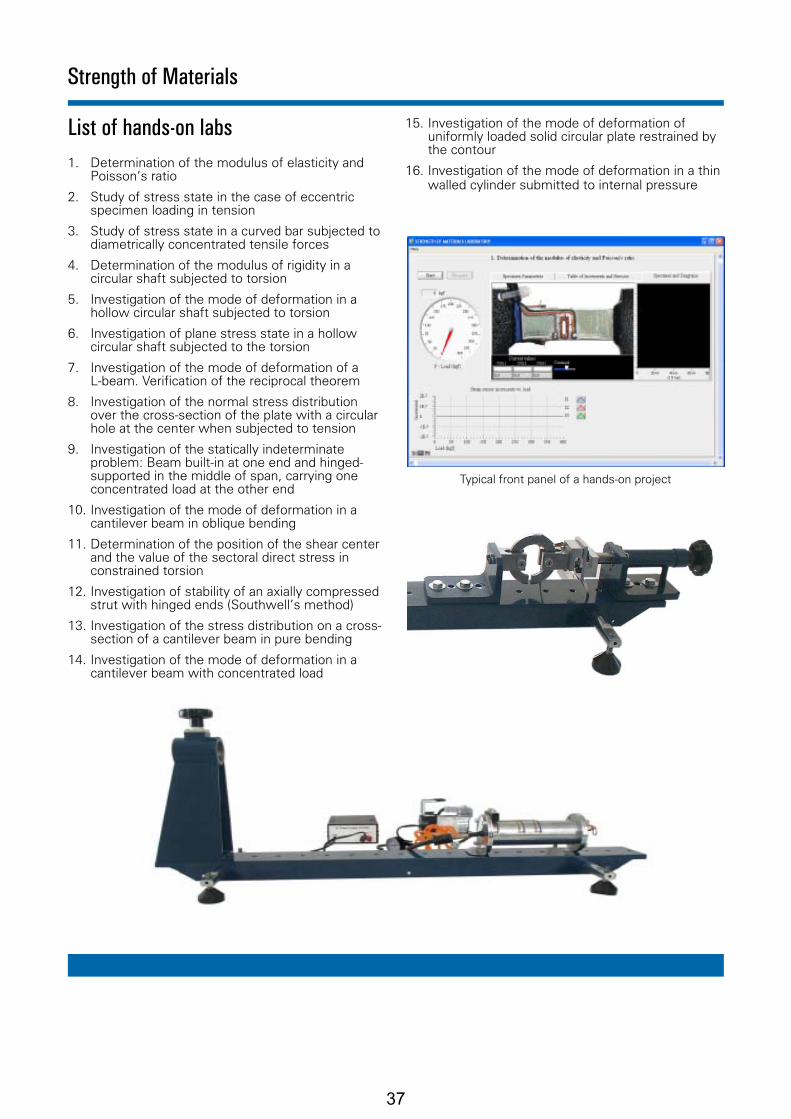
List of hands-on labs1. Determination of the modulus of elasticity and
Poisson’s ratio
2. Study of stress state in the case of eccentric specimen loading in tension
3. Study of stress state in a curved bar subjected to diametrically concentrated tensile forces
4. Determination of the modulus of rigidity in a circular shaft subjected to torsion
5. Investigation of the mode of deformation in a hollow circular shaft subjected to torsion
6. Investigation of plane stress state in a hollow circular shaft subjected to the torsion
7. Investigation of the mode of deformation of a L-beam. Verification of the reciprocal theorem
8. Investigation of the normal stress distribution over the cross-section of the plate with a circular hole at the center when subjected to tension
9. Investigation of the statically indeterminate problem: Beam built-in at one end and hinged-supported in the middle of span, carrying one concentrated load at the other end
10. Investigation of the mode of deformation in a cantilever beam in oblique bending
11. Determination of the position of the shear center and the value of the sectoral direct stress in constrained torsion
12. Investigation of stability of an axially compressed strut with hinged ends (Southwell’s method)
13. Investigation of the stress distribution on a cross-section of a cantilever beam in pure bending
14. Investigation of the mode of deformation in a cantilever beam with concentrated load
15. Investigation of the mode of deformation of uniformly loaded solid circular plate restrained by the contour
16. Investigation of the mode of deformation in a thin walled cylinder submitted to internal pressure
Strength of Materials
Typical front panel of a hands-on project
37

2
NI Compatible Platforms
PXIeCompact RIO Others
1
NI: National Instruments1.
2. Please check with us about compatibility of other NI Platforms
Software
User friendly with easy to use interface
Developed using NI LabVIEW package
Built-in safety features & limitations, and designed for students’ use
Features
Computer based trainer used to teach students how to measure the differenet parameters in rotating machinery including: speed, position and torque
Includes all required sensors to do the different types of measurements
For use with National Instruments Data Acquisition & Control hardware
Curriculum Coverage
Rotary Encoder CharacteristicsPhotoelectric Sensor CharacteristicsMagnetic Pickup & Fly Wheel Sensor Characteristics (with option)Speed Measuring Sensors ComparisonTorque MeasurementMeasuring Speed & Position of the Shaft using the Encoder
Description
Rotating Components are basic parts in almost all industrial machinery; examples are generators, turbines,pumps...etc.
The objective of this trainer is to teach students how to measure the different parameters of rotating machinery, includ-ing speed, torque, and position. The student will learn how to measure the speed of a rotating shaft using different types of speed sensors and comparing between their different behaviors and characteristics. He will also learn how to measure the position of the shaft using a graded disc from 0 to 360 , and how to measure the torque using a torque sensor.
Components
MotorVariable Speed DrivePhotoelectric Sensor Rotary EncoderTorque MeterMag. Pickup & Fly Wheel Sensor (Option)
Rotating Parameters Measurements Trainer
Ordering InformationRotating Parameters Measurements Trainer
For complete product specifications, pricing, and information: e-mail: [email protected] / website: www.ti-acad.jo
*Purchase NI Hardware Separately
RPMT001 - A - B - C
oo
NI* Platform
1... PXIe2... cRIO
Power
1... 110 VAC2... 220 VAC
Options
0... No Option1... Magnetic Pickup & Fly Wheel Sensor
Required NI Modules
PXIe: PXIe-6251, PXI-6514 cRIO: NI-9425, NI-9422, NI-9215, NI-9263
38

Vibration Monitoring and Diagnostics of Rotary and Bearing Systems
OverviewLaboratory stand for hands-on study of Vibration Monitoring and Diagnostics of Rotary and Bearing Systems is based on the NI PXI platform and software developed with the LabVIEW graphical programming language.
The stand consists of a rotary device with loads, imperfection imitators, bearing and sensors; a variable frequency driver is included for motor speed control. Students can accelerate and decelerate the motor, balance the imitators, align the axes, study the effects of various common manufacturing and operational defects ,misalignments, bearing noises. They will also master sensor data processing through the application of mathematical filters and algorithms.
Features ▪ Experimental study of Vibration Monitoring and
Diagnostics of Rotary and Bearing Systems
▪ Menu-driven navigation through the labs
▪ Visual representation of experimental results
Required Hardware and Software ▪ Laboratory stand
▪ Frequency inverter
▪ NI PXI chassis with controller and NI PXI module
▪ Monitor
▪ Windows XP / 7, Microsoft Office
▪ NI LabVIEW
▪ Course software
39

List of labs ▪ Vibrations of an induction motor
▪ Rotary device vibrations in normal operation mode
▪ Vibrations caused by manufacturing defects (misalignment and skew of axis)
▪ Vibrations caused by bearing bore defects
▪ Dependence of a rotary device vibrations on defects of bearings
▪ Dependence of vibration characteristics on the mass of imbalance
▪ Dependence of vibration characteristics on the position of imbalance
▪ Imitation of operating load and its influence on vibration
▪ Dependence of vibration and acoustic parameters on the distance between supports and cantilever mounting
▪ Dependence of total vibrations of a rotary device on vibroinsulation of supports
Vibration Monitoring and Diagnostics of Rotary and Bearing Systems
40

PXIeCompact RIO Others
NI Compatible Platforms1
NI: National Instruments
2
1.
2. Please check with us about compatibility of other NI Platforms
For complete product specifications, pricing, and information: e-mail: [email protected] / website: www.ti-acad.jo
Software
User friendly with easy to use interface
Developed using NI LabVIEW package
Built-in safety features & limitations, and designed for students’ use
Features
Computer based Machine Health Monitoring Trainerused to teach vibration, power and temperature monitoring in rotary motors
Includes all required sensors to measure vibration, temperature and power parameters
For use with National Instruments Data Acquisition & Control hardware
Curriculum Coverage
Introduction to Signal ProcessingAcquiring Physical PhenomenaVibrations FundamentalsShaft Balancing & Bearing FaultsVoltage & Current Waveforms Phasor Diagrams Power Fundamentals & CalculationsHarmonics Temperature Monitoring
Description
The Machine Health Monitoring Trainer is used to demonstrate “Intelligent Maintenance” concepts. Through a series of experiments and investigations that study mechanical and electrical components of a machine, the student is intro-duced to machine health monitoring main parameters; vibration, power and temperature.
Learning to monitor these parameters helps the student better understand machine and components’ degradation that lead to failure.
Students will learn what vibration parameters to monitor for detecting motor balance and bearings status. They will also be introduced to power quality measures contributing to machine health including voltage and current waveforms, harmonics, frequency, active and reactive power, power factor, etc…
Components
Accelerometer Speed Sensor High Speed Motor Speed Controller Bearings Unbalancing ScrewsThermocouple
Machine Health Monitoring Trainer
Ordering InformationMachine Health Monitoring Trainer
MHMT001 - A - B
NI* Platform
1... PXIe2... cRIO
Power
1... 110 VAC2... 220 VAC
*Purchase NI Hardware Separately
Required NI Modules
PXIe: PXIe-4300, PXIe-4353, PXI-4472 cRIO: NI-9225, NI-9227, NI-9211, NI-9234
41
Machine Health Monitoring Trainer
Technical Specifications
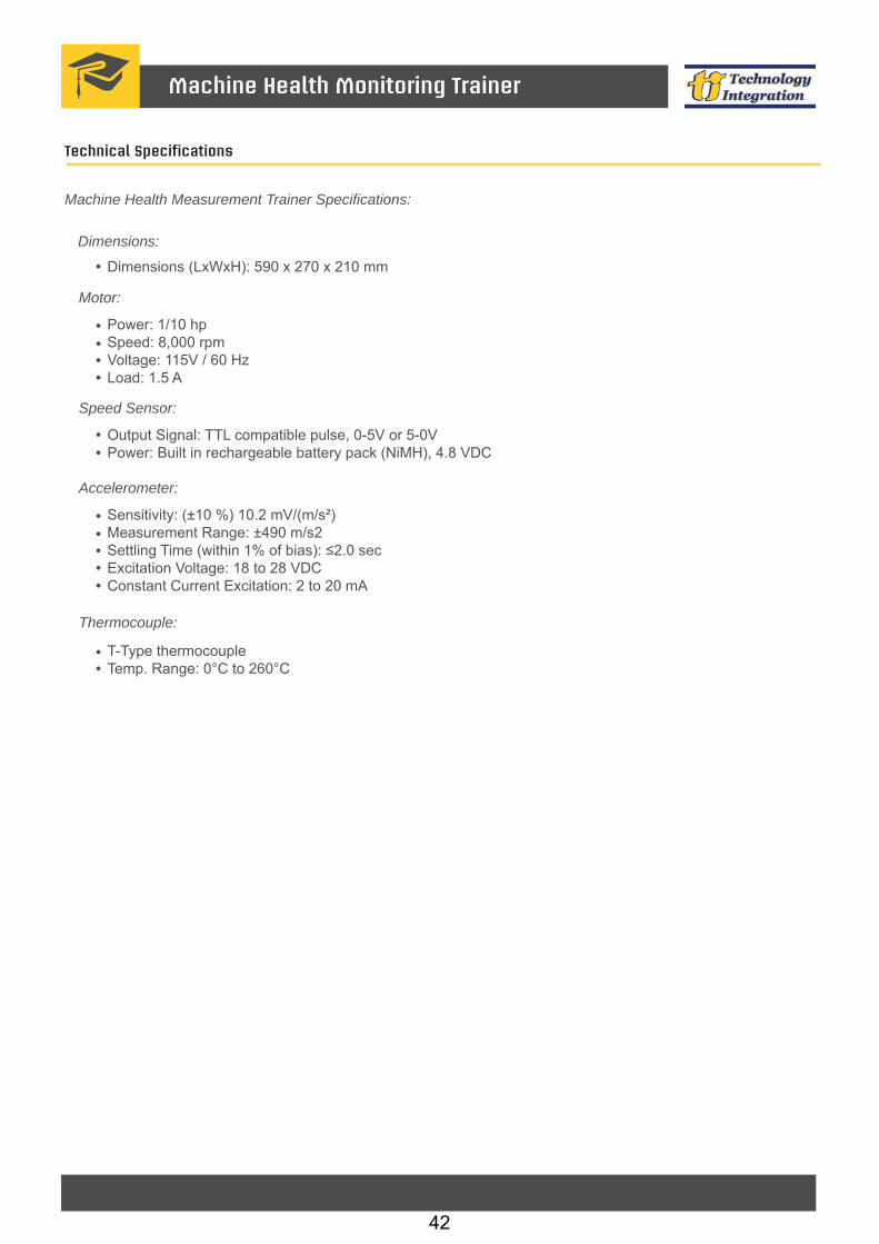
Machine Health Measurement Trainer Specifications:
Dimensions (LxWxH): 590 x 270 x 210 mm
Dimensions:
Power: 1/10 hp Speed: 8,000 rpmVoltage: 115V / 60 HzLoad: 1.5 A
Motor:
Output Signal: TTL compatible pulse, 0-5V or 5-0V Power: Built in rechargeable battery pack (NiMH), 4.8 VDC
Speed Sensor:
Sensitivity: (±10 %) 10.2 mV/(m/s²) Measurement Range: ±490 m/s2Settling Time (within 1% of bias): ≤2.0 secExcitation Voltage: 18 to 28 VDCConstant Current Excitation: 2 to 20 mA
Accelerometer:
T-Type thermocouple Temp. Range: 0°C to 260°C
Thermocouple:
42

Ordering InformationVibration Trainer
NI* Platform
2... cRIO6... PXI
PXICompact RIO Others
NI Compatible Platforms1
NI: National Instruments
2
1.
2. Please check with us about compatibility of other NI Platforms
For complete product specifications, pricing, and information: e-mail: [email protected] / website: www.ti-acad.jo
Features
Computer based Vibration Trainer used to teach vibrations in rotary motors
Includes all required sensors to measure vibration and shaft speed
For use with National Instruments Data Acquisition & Control hardware
Software
User friendly with easy to use interface
Developed using NI LabVIEW package
Built-in safety features & limitations, and designed for students’ use
Curriculum Coverage
Introduction to Signal ProcessingVibration Fundamentals Free Damped & Undamped Vibration Acquiring Vibration Signals Shaft BalancingBearing Faults
Description
Rotating components are basic parts in almost all industrial machinery; examples are generators, turbines, pumps... etc. The objective of using this trainer is to provide students with a systematic and scientific understanding of the vibrations in rotary motors. The trainer comes with an extensive experiments list including basic signal acquisition, signal and fault analysis.
VT001 helps bridge the gap that usually exists between theory and practice. It will help expose the students to numer-ous basic problems relevant to rotating machinery through computer animation, experimental applications, and the use of up-to-date computerized data acquisition hardware.
Components
Accelerometer Speed Sensor High Speed Motor Variable Speed Drive Bearings Unbalancing Screws
Vibration Trainer
VT001 - A - B
*Purchase NI Hardware Separately
Power
1... 110 VAC2... 220 VAC
Required NI Modules
PXI: PXI-4472 cRIO: NI-9234
43

Vibration Trainer
Technical Specifications
Vibration Trainer Specifications:
Dimensions (LxWxH): 590 x 270 x 210 mm
Dimensions:
Power: 1/10 hp Speed: 8,000 rpmVoltage: 115V / 60 HzLoad: 1.5 A
Motor:
Output Signal: TTL compatible pulse, 0-5V or 5-0V Power: Built in rechargeable battery pack (NiMH), 4.8 VDC
Speed Sensor:
Sensitivity: (±10 %) 10.2 mV/(m/s²) Measurement Range: ±490 m/s²Settling Time (within 1% of bias): ≤2.0 secExcitation Voltage: 18 to 28 VDCConstant Current Excitation: 2 to 20 mA
Accelerometer:
44
PXIeCompact RIO Others
NI Compatible Platforms1
NI: National Instruments
2
1.
2. Please check with us about compatibility of other NI Platforms
Software
User friendly with easy to use interface
Developed using NI LabVIEW package
Built-in safety features & limitations, and designed for students’ use
Features
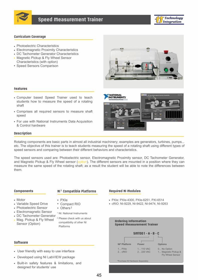
Computer based Speed Trainer used to teach students how to measure the speed of a rotating shaft
Comprises all required sensors to measure shaft speed
For use with National Instruments Data Acquisition & Control hardware
Curriculum Coverage
Photoelectric CharacteristicsElectromagnetic Proximity CharacteristicsDC Tachometer Generator CharacteristicsMagnetic Pickup & Fly Wheel Sensor Characteristics (with option)Speed Sensors Comparison
Description
Rotating components are basic parts in almost all industrial machinery; examples are generators, turbines, pumps... etc. The objective of this trainer is to teach students measuring the speed of a rotating shaft using different types of speed sensors and comparing between their different behaviors and characteristics.
The speed sensors used are: Photoelectric sensor, Electromagnetic Proximity sensor, DC Tachometer Generator, and Magnetic Pickup & Fly Wheel sensor (option). The different sensors are mounted in a position where they can measure the same speed of the rotating shaft; as a result the student will be able to note the differences between them.
Components
MotorVariable Speed Drive Photoelectric SensorElectromagnetic SensorDC Tachometer GeneratorMag. Pickup & Fly WheelSensor (Option)
Speed Measurement Trainer
Ordering InformationSpeed Measurement Trainer
SMT001 - A - B - C
NI* Platform
1... PXIe2... cRIO
For complete product specifications, pricing, and information: e-mail: [email protected] / website: www.ti-acad.jo
Power
1... 110 VAC2... 220 VAC
*Purchase NI Hardware Separately
Options
0... No Option1... Magnetic Pickup & Fly Wheel Sensor
Required NI Modules
PXIe: PXIe-4300, PXIe-6251, PXI-6514 cRIO: NI-9229, NI-9422, NI-9474, NI-9263
45

Speed Measurement Trainer
Technical Specifications
Speed Measurement Trainer Specifications:
Dimensions (LxWxH): 690 x 270 x 210 mm
Dimensions:
Power: 1/10 hpSpeed: 8,000 rpmVoltage: 115V / 60 HzLoad: 1.5 A
Motor:
Sensing distance: 7m Housing material: Plastic, nickel plated brass and stainless steelEnclosure rating: IP67Operating voltage range: 10 to 30 VDC
Photoelectric Sensor:
Inertia: 1.23 x 10 oz-in-secV/1000 RPM: 2.6 VSpeed: 12,000 rpm
DC Tachometer Generator:
Sensing method: Inductive typeSensing distance: 16 mm ±10%Sensing object: Ferrous metalOperating voltage range: 10 to 32 VDCCurrent consumption: 10 mA MaxControl output: NPN open collector output
Electromagnetic Sensor:
2-4
46

PXIeCompact RIO Others
NI Compatible Platforms1
NI: National Instruments
2
1.
2. Please check with us about compatibility of other NI Platforms
Software
User friendly with easy to use interface
Developed using NI LabVIEW package
Built-in safety features & limitations, and designed for students’ use
Features
Computer based Speed Trainer used to teach students how to measure the position of a rotating shaft
Includes all required sensors to measure shaft speed
For use with National Instruments Data Acquisition & Control hardware
Curriculum Coverage
Photoelectric CharacteristicsRotary Encoder CharacteristicsElectromagnetic SensorSpeed Sensors Comparison
Description
Rotating components are basic parts in almost all industrial machinery; examples are generators, turbines, pumps... etc.
The objective of this trainer is to teach students how to measure the position of a rotating shaft using speed & position sensors, and using a graded disc from 0 to 360 . In addition, the student will have the chance to compare between the characteristics and behavior of different speed sensors; as a result the student will be able to note the differences between them.
Components
MotorVariable Speed Drive Photoelectric SensorElectromagnetic SensorRotary Encoder Sensor
Position Measurement Trainer
Ordering InformationPosition Measurement Trainer
For complete product specifications, pricing, and information: e-mail: [email protected] / website: www.ti-acad.jo
*Purchase NI Hardware Separately
PMT001 - A - B
NI* Platform
1... PXIe2... cRIO
Power
1... 110 VAC2... 220 VAC
o o
Required NI Modules
PXIe: PXIe-6251, PXI-6514 cRIO: NI-9425, NI-9422, NI-9263
47

RF Basics and Components Laboratory
OverviewThe RF Components Test Bench is an educational package for RF hardware design and study of signal transmission basics.
The Test Bench is designed for study of operating principles, characterization of various RF hardware components, as well as for getting a basic understanding of RF hardware design principles.
The students have the flexibility to mix and match the training kit modules for building various RF subsystems. Measurement software demonstrates the use of graphical programming of instruments, measurement automaton and visualization of test results.
Features ▪ Menu-driven navigation through the labs
▪ Easy to use graphical user interface
▪ Hands-on experiments on the workbench and on the RF system
▪ Step-by-step instructions for students
▪ Study guide with screen video for each experiment
Required Hardware and Software ▪ NI PXI RF Signal Analyzer (5661/63)
▪ NI PXI RF Signal Generator (5671/73)
▪ RF Components Testbench
▪ Labview 2009 or higher
▪ NI Modulation Toolkit
▪ NI Spectral Measurements Toolkit
48

List of labs ▪ Basic RF concepts
▪ Analog and digital modulations
� AM/FM/PM
� FSK/PSK/QAM
▪ RF circuit design concepts
▪ RF transmitter concepts
▪ RF receivers concepts
▪ Active and passive RF components
� Local oscillators
� RF filters
� RF signal attenuators
� RF signal amplifiers
� RF signal mixers
RF Basics and Components Laboratory
49

Laboratory Facility on Antennas
OverviewThe laboratory facility is intended for hands-on study of radiational patterns of antennas. The facility is based on the NI RF PXI platform and uses software developed with the LabVIEW graphical programming language.
All hands-on experiments are implemented on the facility consisting of a turntable tripod used for mounting the antennas under test, a tripod for the auxiliary antenna, and a set of 7 antennas in the 2.4GHz range. Signal received by the antenna under test is fed to the RF spectrum analyzer for further processing.
The facility allows the students to measure the parameters of studied antennas by using the method of far field measurements.
Features ▪ 6 hands-on experiments on measuring the
radiational patterns of antennas
▪ Graphical representation of experimental results
Required Hardware and Software ▪ Windows XP, Microsoft Office
▪ LabVIEW Full Development System for Windows
▪ NI Spectral Measurement Toolkit
▪ Laboratory facility consisting of a tripod, a tripod with a turntable and a set of antennas
▪ A set of RF PXI hardware
▪ PC Monitor
50

Laboratory Facility on Antennas
List of labs1. Study of radiation patterns of dipole
antennas. Rod antenna.
2. Study of radiation patterns of biquadratic antennas.
3. Study of radiation patterns of YAGI antennas.
4. Study of radiation patterns of horn antennas.
5. Study of radiation patterns of parabolic antennas.
6. Study of radiation patterns of cophasal antenna arrays.
ANTENNAS INCLUDED WITH THE LABORATORY FACILITY
1. Rod antenna.
2. Biquadratic antenna.
3. YAGI antenna.
4. Horn antenna.
5. Parabolic antenna.
6. Cophasal antenna array.
7. Auxiliary rod antenna.
Antenna Pattern Measurement
REQUIRED NI HARDWARE
1. PXIe-1065 (18-Slot 3U PXIe/PXI Chassis)
2. NI PXIe-8130 (Turion 64 X2 2.3 GHz).
3. NI PXI-5661 (2.7 GHz RF Vector Signal Analyzer with Real Time Streaming & Analysis).
4. NI PXI-5671 (2.7 GHz RF VSG, Onboard Signal Processing).
5. NI PXI-4130 and APS-4100 (Power SMU and APS-4100 Power Supply).
6. NI PXI-6251 (16 Analog Inputs, 24 Digital I/O, 2 Analog Outputs).
Parabolic antenna
Cophasal antenna array
YAGI antenna
Biquadratic antenna Rod antenna (under test)
Rod antenna (auxiliary)
Horn antenna
51

RADAR Signal Analysis
OverviewFollowing are main advantages of this system:
1. Real-Time processing, following are functions that are being performed on FPGA
▪ Digital down conversion
▪ Gaussian filter
▪ Pulse compression
▪ Digital up conversion
2. In total 6 different laboratory works for in depth analyses of Radar signal basics
3. Processing in presence of active and passive noises
4. Ability to generate 2 different objects, change time delay between objects
Note: Demo software is available per request.
List of labs1. Device for matched filtering and forming of the
pulse signal with linear frequency modulation.
The purpose of the laboratory work is to study the properties of the pulse signal with linear frequency modulation (LFM), familiarization with the principles of construction and performance of digital matched filtering.
2. Device for forming and matched filtering of the pulse signal with pseudorandom phase-manipulation.
The purpose of the laboratory work is to study the properties of the pulse signal with pseudorandom phase shift keying (PSK) on Barker code, introduction to the principles of construction and performance of digital matched filtering.
52
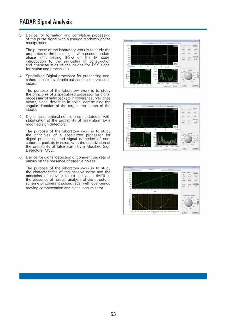
3. Device for formation and correlation processing of the pulse signal with a pseudo-randomly phase manipulation.
The purpose of the laboratory work is to study the properties of the pulse signal with pseudorandom phase shift keying (PSK) on the M code, introduction to the principles of construction and characteristics of the device for PSK signal formation and processing.
4. Specialized Digital processor for processing non-coherent packets of radio pulses in the surveillance radars.
The purpose of the laboratory work is to study the principles of a specialized processor for digital processing of radio packets in coherent surveillance radars, signal detection in noise, determining the angular direction of the target (the center of the stack).
5. Digital quasi-optimal non-parametric detector with stabilization of the probability of false alarm by a modified sign detectors.
The purpose of the laboratory work is to study the principles of a specialized processor for digital processing and signal detection of non-coherent packets in noise, with the stabilization of the probability of false alarm by a Modified Sign Detectors (MSD).
6. Device for digital detection of coherent packets of pulses on the presence of passive noises.
The purpose of the laboratory work is to study the characteristics of the passive noise and the principles of moving target indication (MTI) in the presence of noises, analysis of the structural scheme of coherent pulsed radar with over-period moving compensation and digital accumulator.
RADAR Signal Analysis
53

Engine ECU Test and Debug Laboratory
OverviewThe laboratory facility for hands-on study of Engine - ECU tests and debugging is based on the NI PXI platform working in conjunction with the RIO expansion chassis. The software has been developed in the LabVIEW graphical programming environment and Veristand.
The students can study the operation of vehicle engine and ECU, controling and monitoring simulated parameters from sensors and the environment based on the hardware-in-the-loop technology and NI Veristand software for real-time testing and simulation.
Simulated model of a 6 cylinder engine is running on a real-time PXI controller, while DAQ, FPGA, & CAN are used for communication with the ECU, Throttle Body, and instrument cluster.
Course manual is embedded into the lab software for easy access to theoretical materials during the lab. The software is flexible for development and can be extended through the use of other software environments such as LabVIEW, NI TestStand, etc.
Features ▪ 10 hands-on experiments
▪ Graphical representation of experimental results
▪ Hardware in the loop testing experience
▪ Real-time model execution on the controller
▪ Automatic gearbox operation
Required Hardware and Software ▪ Dual operating system, controller for RT
simulation of the Engine, as well as Host interfacing on Windows
▪ Mathematical model for 6 cylinder engine
▪ NI PXI system with expansion chassis and I/Os
▪ Standard ECU for 6 cylinder engine control, throttle body, instrument cluster
▪ Measurement and control modules for interfacing with the ECU
▪ Lab Software (based on Veristand) with the Course Manual
▪ Speakers for engine noise imitation
54

List of hands-on labs1. Understanding the Hardware In The Loop System
2. Running the Engine - ECU Lab in Demo mode
3. Modeling the transfer function of the general engine
4. Determining the characteristics of Engine and Automatic gear box
5. Determining vehicle speed characteristics
6. Determining engine load profile
7. Engine operation, visual representation
8. ECU calibration and diagnostics using CAN
9. The influence of number of steps in gearbox on the loading profile of engine
10. Insertion of faults on various sensors and the investigation of their influence on the operation of engine
Engine - ECU Test and Debug Laboratory
Typical front panel of a hands-on demo
55
Solar Laboratory
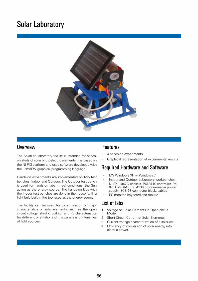
OverviewThe SolarLab laboratory facility is intended for hands-on study of solar photoelectric elements. It is based on the NI PXI platform and uses software developed with the LabVIEW graphical programming language.
Hands-on experiments are implemented on two test benches: Indoor and Outdoor. The Outdoor test bench is used for hands-on labs in real conditions, the Sun acting as the energy source. The hands-on labs with the Indoor test benches are done in the house (with a light bulb built-in the tool used as the energy source).
The facility can be used for determination of major characteristics of solar elements, such as the open circuit voltage, short circuit current, I-V characteristics for different orientations of the panels and intensities of light sources.
Features ▪ 4 hands-on experiments
▪ Graphical representation of experimental results
Required Hardware and Software ▪ MS Windows XP or Windows 7 ▪ Indoor and Outdoor Laboratory workbenches ▪ NI PXI 1042Q chassis, PXI-8110 controller, PXI
6251 M-DAQ, PXI 4130 programmable power supply, SCB-68 connector block, cables
▪ PC monitor, keyboard and mouse
List of labs1. Voltage on Solar Elements in Open circuit
Mode.2. Short Circuit Current of Solar Elements.3. Current-voltage characterization of a solar cell.4. Efficiency of conversion of solar energy into
electric power.
56

PXIeCompact RIO Others
NI Compatible Platforms1
NI: National Instruments
2
1.
2. Please check with us about compatibility of other NI Platforms
Features
Computer based Fuel Cell Trainer
Includes all required sensors to measure the light intensity, temperature, voltage and current
For use with National Instruments Data Acquisition & Control hardware
Curriculum Coverage
Solar Cell CharacteristicsSolar Cell as DiodeElectrolysis Characteristics Fuel Cell Characteristics
Description
Fuel cells are one of the key technologies of the 21st Century. Today manufacturers worldwide are actively engaged in developing fuel cells for use in mobile devices, automobiles and stationary power plants.
The Fuel Cell Trainer setup is designed as a quick and easy way to introduce the concepts of energy conversion and fuel cells. This unique package allows instructors to quickly demonstrate the concepts of using solar or kinetic energy as a power source for an electrolyser, which will in turn, produce hydrogen that will be used to feed a fuel cell, from which a load will be powered. A great tool for exposing students to the technologies of tomorrow and introducing “green energy” alternatives.
Components
Software
User friendly with easy to use interface
Developed using NI LabVIEW package
Built-in safety features & limitations, and designed for students’ use
Fuel Cell Trainer
Ordering InformationFuel Cell Trainer
FCT001 - A - B - C
NI* Platform
1... PXIe2... cRIO
For complete product specifications, pricing, and information: e-mail: [email protected] / website: www.ti-acad.jo
Power
1... 110 VAC2... 220 VAC
Electrolyzer Battery
1... Solar Cell2... Wind Mill3... Solar Cell & Wind Mill
Solar Panel PEM Fuel Cell PEM Electrolyser Load Box Light Source Wind Mill (Option)
*Purchase NI Hardware Separately
Required NI Modules
PXIe: PXIe-6251 cRIO: NI-9219, NI-9263
57

Fuel Cell Trainer
Technical Specifications
Solar Cell:
Dimensions (LxWxH): 70 x 120 x 52 mmOpen circuit voltage: 3.0 V DCShort circuit current: 245 mAVoltage (at maximum power point): 2.4 V DCCurrent (at maximum power point): 200 mAPower output: 0.48 W
Solar Module:
Electrolyzer type: Polymer electrolyte membrane (PEM)Dimensions (LxWxH): 85 x 190 x 90 mmPower consumption: 1.0 WRequired voltage: 1.4 – 1.8 VMaximum current: 0.5 AStorage volume of hydrogen and oxygen: 10 ml eachRate of hydrogen production: 3.5 ml/min (at 05 A)Consumption of distilled water: 0.1 ml/h at 0.3 A
PEM Electrolyzer:
Fuel cell type: Polymer electrolyte membrane (PEM)Dimensions (L x W x H): 85 x 70 x 70 mmPower output: 0.5 WVoltage output: 0.4 – 1.0 VRate of hydrogen consumption: 7 ml/min (at 1.0 A)
PEM Fuel Cell:
7-position variable resistance: 1,3, 5, 10, 50, 100, 200 ohmMotor operating voltage: 0.2 – 3 V DCMotor current: 10 – 15 mALamp operating voltage: 1.5 V DCLamp current: 80 mA
Loads:
Wind Mill (option):
Miniature wind turbine (wind power generator) Includes 3 different types of profiled blades and 1 type of Poly-propylene sheet blades in a complete package3 Phase AC alternator similar to the one used in real commercial wind turbineDimensions: - Base to top of rotor body: 31 cm - Blade sweep diameter: 36 cm
Wind Turbine:
58

Smart and Integrated Power Monitoring SCADA Educational System
OverviewThe laboratory facility gives a chance to operator/student to understand the state of the art Smart Grid SCADA Systems in user friendly, safe, easy to use and office environment.
Features ▪ The educational system is a copy of existing real
power monitoring, substation control and data acquisition SCADA system.
▪ The automatic monitoring and control units (RTU) of substations are implemented on Nl cRIO
▪ platform.
▪ The specialized control software is implemented in LabView graphical programming language.
▪ The software visualizes the virtual operating diagrams (single line diagram) of the substations.
▪ It allows interactive monitoring and control over any existing apparatus.
▪ The Laboratory Stand allows hardware simulation of real emergency situations without any real risk for operator/student.
▪ Operator/student can learn the work of the real SCADA system.
▪ Operator/student can add/modify different parts of the system.
Configuration ▪ Main Communication Server (MCS): includes real
time and historical databases and communication gateway
▪ Engineering Workstation (EWS): incIudes LabView graphical programming language to add/modify different parts of the system
▪ Operator Workstationl (OWS1): includes SCADA monitoring and control, basic power quality monitoring and configuration of settings
▪ Operator Workstation2 (OWS2): includes advanced power quality monitoring
▪ Laboratory Stand: includes all RTUs and hardware emulation of substation
59
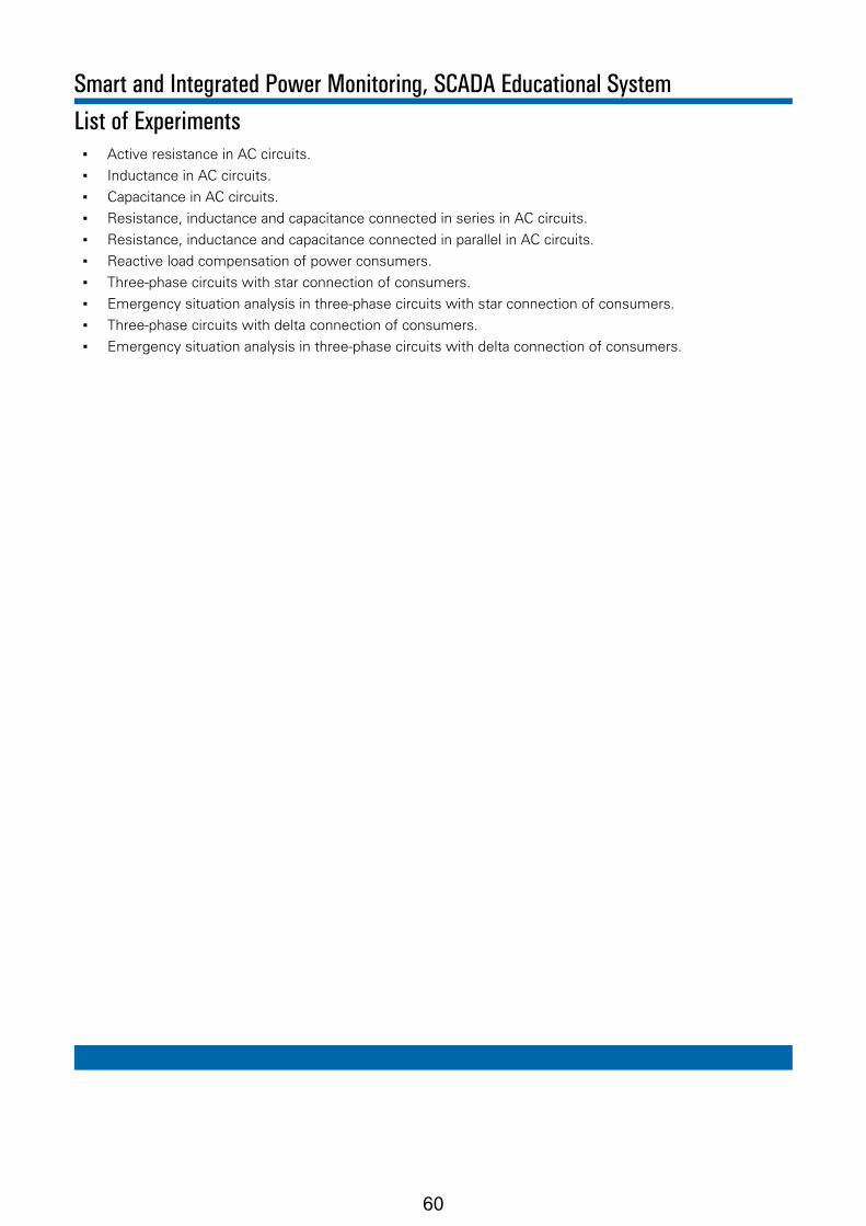
List of Experiments ▪ Active resistance in AC circuits.
▪ Inductance in AC circuits.
▪ Capacitance in AC circuits.
▪ Resistance, inductance and capacitance connected in series in AC circuits.
▪ Resistance, inductance and capacitance connected in parallel in AC circuits.
▪ Reactive load compensation of power consumers.
▪ Three-phase circuits with star connection of consumers.
▪ Emergency situation analysis in three-phase circuits with star connection of consumers.
▪ Three-phase circuits with delta connection of consumers.
▪ Emergency situation analysis in three-phase circuits with delta connection of consumers.
Smart and Integrated Power Monitoring, SCADA Educational System
60

SMART GRID SCADA System Educational Stand
OverviewThe laboratory facility is designed for hands-on study of Smart Grid SCADA System for power. Generation, Transmission, Distribution, Utilization. The simulation of the Smart Grid subsystems are implemented in hardware using Nl PXI platform. The automatic monitoring and control systems are implemented in hardware using Nl cRIO platform.
Laboratory facility is giving chance for students to understand the state of the art Smart Grid Systems in user friendly, safe, easy to use and classroom environment.
Features ▪ The simulation of mentioned subsystems for the
Smart Grid are implemented on Nl PXI platform.
▪ The automatic monitoring and control systems of facilities were implemented on Nl cRIO platform.
▪ The specialized control software is implemented in LabView graphical programming language.
▪ The software visualizes the virtual operating diagrams of the facilities. It allows interactive monitoring and control over any modeled processes. It is also possible to simulate emergency situations.
▪ Simulation of any real emergency situations without any real risks.
▪ The system is simulating the environment and the subsystems. The monitoring and control parts are implemented on separate controllers. They have the software, which has the same algorithms as in real running systems.
61
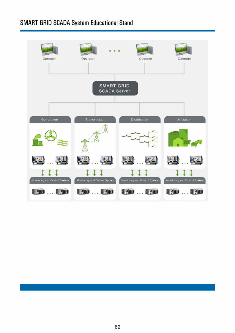
SMART GRID SCADA System Educational Stand
62
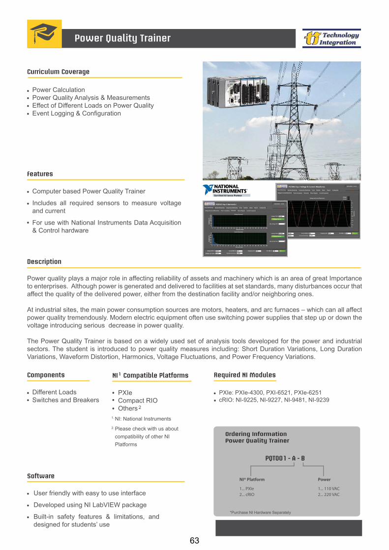
PXIeCompact RIO Others
NI Compatible Platforms1
NI: National Instruments
2
1.
2. Please check with us about compatibility of other NI Platforms
Software
User friendly with easy to use interface
Developed using NI LabVIEW package
Built-in safety features & limitations, and designed for students’ use
Features
Curriculum Coverage
Power CalculationPower Quality Analysis & Measurements Effect of Different Loads on Power QualityEvent Logging & Configuration
Description
Power quality plays a major role in affecting reliability of assets and machinery which is an area of great Importance to enterprises. Although power is generated and delivered to facilities at set standards, many disturbances occur that affect the quality of the delivered power, either from the destination facility and/or neighboring ones.
At industrial sites, the main power consumption sources are motors, heaters, and arc furnaces – which can all affect power quality tremendously. Modern electric equipment often use switching power supplies that step up or down the voltage introducing serious decrease in power quality.
The Power Quality Trainer is based on a widely used set of analysis tools developed for the power and industrial sectors. The student is introduced to power quality measures including: Short Duration Variations, Long Duration Variations, Waveform Distortion, Harmonics, Voltage Fluctuations, and Power Frequency Variations.
Components
Different LoadsSwitches and Breakers
Power Quality Trainer
Computer based Power Quality Trainer
Includes all required sensors to measure voltage and current
For use with National Instruments Data Acquisition & Control hardware
Ordering InformationPower Quality Trainer
*Purchase NI Hardware Separately
PQT001 - A - B
NI* Platform
1... PXIe2... cRIO
Power
1... 110 VAC2... 220 VAC
Required NI Modules
PXIe: PXIe-4300, PXI-6521, PXIe-6251cRIO: NI-9225, NI-9227, NI-9481, NI-9239
63

Smart Grid - Power Quality Analysis and Control
OverviewThe facility has been designed for hands-on study of the methods of power quality and power consumption control in single- and three-phase power networks. It can also be used for monitoring of power quality in the power distribution network, along with monitoring of power consumption rate by the consumers.
The facility can be operated as a standalone device, in conjunction with a personal computer with monitor or with a PC-based SCADA server to which multiple units can be connected. Besides being a training facility for hands-on study the system can also be used as a smart meter for all kinds of electrical measurements on three-phase power networks.
Features ▪ 10 hands-on labs of power quality monitoring and
control.
▪ Menu-driven navigation through the labs.
▪ Visual representation of experimental results.
▪ Data exchange with remote measurement device.
▪ Emergency alarms and alarm management.
List of Experiments ▪ Active resistance in AC circuits.
▪ Inductance in AC circuits.
▪ Capacitance in AC circuits.
▪ Resistance, inductance and capacitance connected in series in AC circuits.
▪ Resistance, inductance and capacitance connected in parallel in AC circuits.
▪ Reactive load compensation of power consumers.
▪ Three-phase circuits with star connection of consumers.
▪ Emergency situation analysis in three-phase circuits with star connection of consumers.
▪ Three-phase circuits with delta connection of consumers.
▪ Emergency situation analysis in three-phase circuits with delta connection of consumers.
64
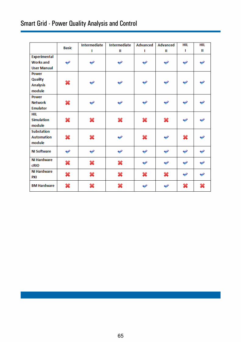
Smart Grid - Power Quality Analysis and Control
65

Relay Protection of Power Plants and Substations
OverviewLaboratory facility has been designed for hands-on study of relay protection circuits in power generating plants and power distribution substations. The automatic monitoring and control system of the facility is compatible with a NI PXI-based control system. Specialized control software is implemented in LabView graphical programming language. The software visualizes a virtual operating diagram of the facility and allows interactive monitoring and control over any modeled processes and simulated in hardware emergency situations.
Relay protection for power plantsThe facility consists of an engine unit, a generator, a relay protection circuit for the generator, and a module with several types of relays: reverse power relay (microprocessor control, implemented in NI PXI), blinker relay, interposing relay, over voltage protection relay, under voltage protection relay, timing relay, thermal protection relay. The facility contains a generator producing electric power, with protection circuits (over and under voltage protection, thermal protection). Remote protection of the power network is implemented with the use of state-of–the-art microprocessor-controlled unit, implemented on the basis of National Instruments PXI controller. Students can model emergency situations to study respective processes and situations.
Relay protection for power substationsThe facility has real protective circuits and a module with integrated relays of different types: differential relay (microprocessor control implemented in NI PXI), overcurrent relay, current cutoff relay, blinker relays, interposing relay and timing relay. The students can simulate different emergency situations and control the elements of the facility, recovering the operation of the substation after emergency. It is possible to connect a second personal computer to the facility enabling simultaneous work of two students with the facility (one student may work with the power generating unit while the other may use the power distribution substation unit).
66
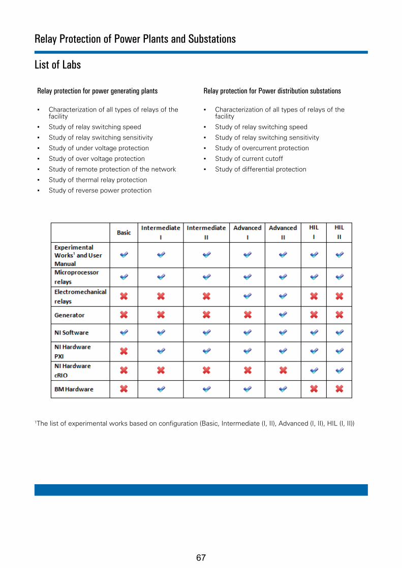
List of Labs
Relay protection for power generating plants Relay protection for Power distribution substations
▪ Characterization of all types of relays of the facility
▪ Study of relay switching speed
▪ Study of relay switching sensitivity
▪ Study of under voltage protection
▪ Study of over voltage protection
▪ Study of remote protection of the network
▪ Study of thermal relay protection
▪ Study of reverse power protection
▪ Characterization of all types of relays of the facility
▪ Study of relay switching speed
▪ Study of relay switching sensitivity
▪ Study of overcurrent protection
▪ Study of current cutoff
▪ Study of differential protection
1The list of experimental works based on configuration (Basic, Intermediate (I, II), Advanced (I, II), HIL (I, II))
Relay Protection of Power Plants and Substations
67
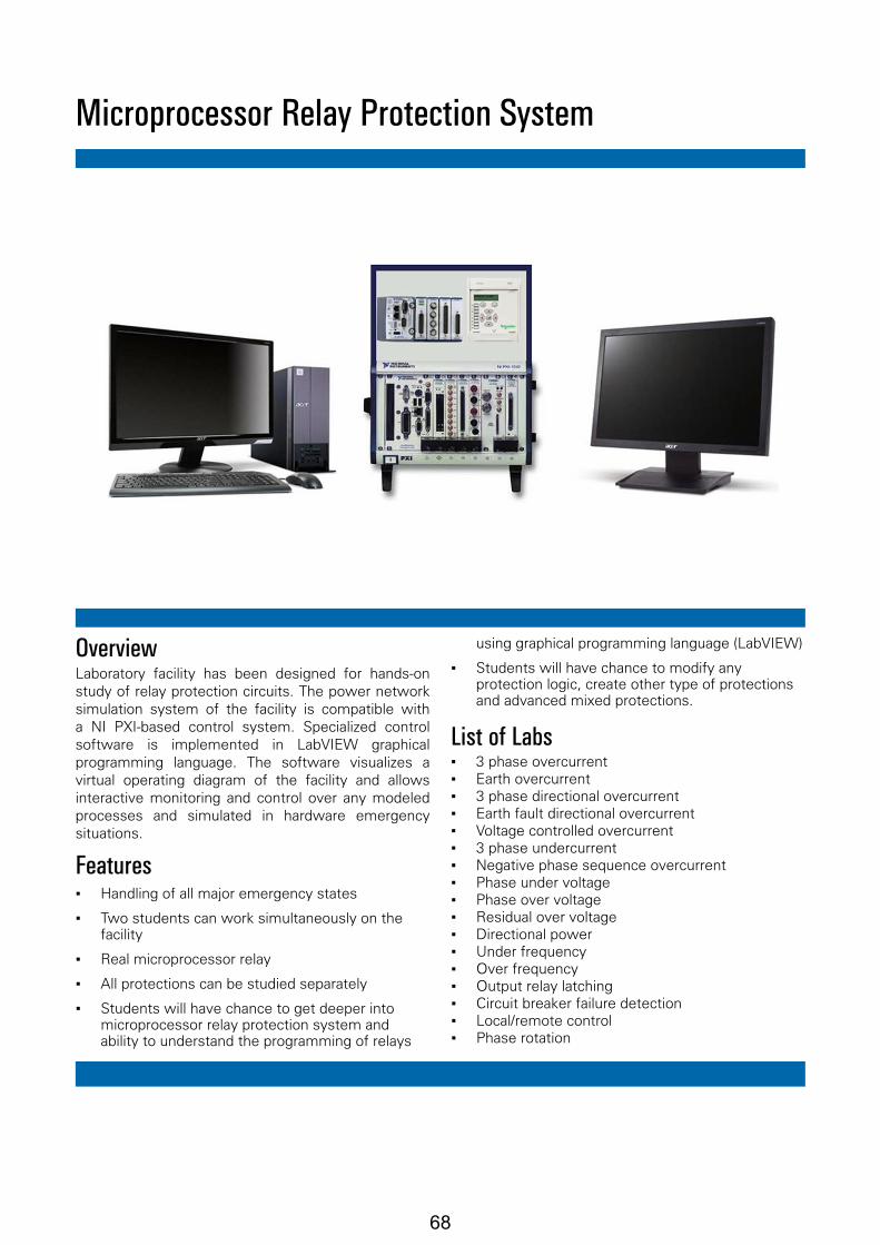
Microprocessor Relay Protection System
OverviewLaboratory facility has been designed for hands-on study of relay protection circuits. The power network simulation system of the facility is compatible with a NI PXI-based control system. Specialized control software is implemented in LabVIEW graphical programming language. The software visualizes a virtual operating diagram of the facility and allows interactive monitoring and control over any modeled processes and simulated in hardware emergency situations.
Features ▪ Handling of all major emergency states
▪ Two students can work simultaneously on the facility
▪ Real microprocessor relay
▪ All protections can be studied separately
▪ Students will have chance to get deeper into microprocessor relay protection system and ability to understand the programming of relays
using graphical programming language (LabVIEW)
▪ Students will have chance to modify any protection logic, create other type of protections and advanced mixed protections.
List of Labs ▪ 3 phase overcurrent ▪ Earth overcurrent ▪ 3 phase directional overcurrent ▪ Earth fault directional overcurrent ▪ Voltage controlled overcurrent ▪ 3 phase undercurrent ▪ Negative phase sequence overcurrent ▪ Phase under voltage ▪ Phase over voltage ▪ Residual over voltage ▪ Directional power ▪ Under frequency ▪ Over frequency ▪ Output relay latching ▪ Circuit breaker failure detection ▪ Local/remote control ▪ Phase rotation
68

Software
User friendly with easy to use interface
Developed using NI LabVIEW package
Built-in safety features & limitations, and designed for students’ use
Features
Computer based Process Trainer used to teach level, flow, temperature, and pressure Control
Includes all required sensors to measure different process variables
For use with National Instruments Data Acquisition & Control hardware
Curriculum Coverage
Acquiring Physical PhenomenaOn/Off Control PID Feedback Control Setpoint Profile Generation Lead-Lag Compensation Feedback/Feedforward Control Multiloop Cascade Control Ratio ControlFlow Meters Comparison (with option)
Description
A bench-mount trainer for teaching Process Control through level, flow, temperature, and pressure. The PT001 trainer includes all the required sensors and actuators to perform the full experiment list for teaching process control. Using PT001, the student will acquire better understanding and hands-on experience in process control.
The PT001 was developed for use with National Instruments measurement and control platforms. It utilizes the platform features such as; real-time and FPGA processing, intelligent communication interfaces, rugged I/O modules, among others. The industrial I/O modules filter, calibrate, and scale raw sensor signals to engineering units and performs self diagnostics.
The curriculum covered includes teaching the principles of On/Off Control, PID control, Feedforward and other types of control used in the industry.
Process Trainer
Ordering InformationProcess Trainer
PT001 - A - B - C
*Purchase NI Hardware Separately
NI* Platform
1... PXIe2... cRIO
Power
1... 110 VAC2... 220 VAC
PXIeCompact RIO Others
NI Compatible Platforms1
NI: National Instruments
2
1.
2. Please check with us about compatibility of other NI Platforms
Components
Thermocouples Heater Level Sensor Pressure Sensor Magnetic Flow Meters Flow Control Valve PumpVariable Frequency DriveTurbine Flow Meter (Option)
Options
0... No Option1... Turbine Flow Meter
Required NI Modules
PXIe : PXI-6236, PXIe-6251, PXI-6513, PXIe-4353 3
cRIO: NI-9219, NI-9203, NI-9474, NI-9263PXIe: for Turbine Flow Meter option, replace PXI-6236 with PXI-6238
3.
69

Process Trainer
Technical Specifications
Process Trainer Specifications:
Dimensions (LxWxH): 1200 x 700 x 600 mmLower Tank Dimensions: 400 x 255 x 205 mmUpper Tank Dimensions: 300 x 255 x 205 mmLower Tank Volume: 18.7 LitersUpper Tank Volume: 14 Liters
Dimensions & Volumes:
Pressure: 10 BarsPower: 115 Watts
Maximum allowable temperature: 55 °CMaximum allowable water level in the upper tank: 23 cm
Safety Considerations:
Heater Power: 2000 Watts
Heater:
Upper: 4-5 Liters/minuteLower: 11-12 Liters/minute
Maximum Flow Rate:
Pump:
70

PXIeCompact RIO Others
NI Compatible Platforms1
NI: National Instruments
2
1.
2. Please check with us about compatibility of other NI Platforms
Software
User friendly with easy to use interface
Developed using NI LabVIEW package
Built-in safety features & limitations, and designed for students’ use
Features
Computer based Flow Measurement Trainer used to teach flow sensing technologies
Includes all required sensors to measure flow
For use with National Instruments Data Acquisition & Control hardware
Curriculum Coverage
Magnetic Flow Meter CharacteristicsPaddle Wheel Flow Meter Characteristics Differential Pressure Flow Meter CharacteristicsVortex Flow Meter Characteristics (with option) Comparison between Flow Meters
Description
FMT001 is a bench-mount trainer that is used to teach students how to measure flow between two tanks using differ-ent flow measuring devices; Magnetic Flow Meter, Paddle Wheel Flow Meter, Venturi Flow Meter, Rota Meter and Vortex Flow Meter (option).
Developed for use with a wide variety of National Instruments data acquisition and control platforms - easy-to-use, highly expandable programmable automation controllers, intelligent communication interfaces, and rugged I/O mod-ules. These industrial I/O modules filter, calibrate, and scale raw sensor signals to engineering units and perform self-diagnostics to look for problems.
The curriculum covered includes understanding the characteristics of the different flow measuring devices and com-paring between their different behaviors and characteristics.
Components
Pump Magnetic Meter Paddle Wheel Meter Diff. Pressure Meter Rota Meter Flow Control Valve Vortex Flow Meter (Option)
Flow Measurement Trainer
Ordering InformationFlow Measurement Trainer
FMT001 - A - B - C
NI* Platform
1... PXIe2... cRIO
Power
1... 110 VAC2... 220 VAC
Options
0... No Option1... Vortex Flow Meter
*Purchase NI Hardware Separately
Required NI Modules
PXIe: PXI-6236, PXIe-6251, PXI-6514 cRIO: NI-9215, NI-9203, NI-9474, NI-9263, NI-9422
71
Maximum allowable temperature: 55 °CMaximum allowable water level in the upper tank: 23 cm
Flow Measurement Trainer
Technical Specifications
Flow Measurement Trainer Specifications:
Dimensions (LxWxH): 1200 x 700 x 600 mmLower Tank Dimensions: 400 x 255 x 205 mmUpper Tank Dimensions: 300 x 255 x 205 mmLower Tank Volume: 18.7 LitersUpper Tank Volume: 14 Liters
Dimensions & Volumes:
Pressure: Max. 10 BarsPower: 115 Watts
Flow Rate: 0.01-0.5 … 35-700 L/minMaximum pressure: 10 BARMaximum temperature: 80 °COutput: 4-20 mA, 3-wireMax. Load: 500 ΩPower Supply: 24 VDCPower Consumption: 80 mA
Electromagnetic Flow Meter:
Upper: 4-5 Liters/minuteLower: 11-12 Liters/minute
Maximum Flow Rate:
Pump:
Flow Rate: 0.5-3.3,….,300-2350 L/Min. waterOutput: 4-20 mA, 3-wireMaximum pressure: 10 BARMaximum temperature 80 °CPower Supply: 24 VDCPower Consumption: 100 mA
Differential Pressure Flow Meter:
Flow Rate: 1-26 L/min waterOutput: 4-20 mA, 3-wireMaximum pressure: 16 BARMaximum temperature: 80 °CPower Supply: 24 VDCPower Consumption: 15 mA
Rotating Vane Flow Meter:
Safety Considerations:
72

PXIeCompact RIO Others
NI Compatible Platforms1
NI: National Instruments
2
1.
2. Please check with us about compatibility of other NI Platforms
Software
User friendly with easy to use interface
Developed using NI LabVIEW package
Built-in safety features & limitations, and designed for students’ use
Features
Computer based Flow Control Trainer used to teach Flow Control
Includes all required sensors to measure the flow
For use with National Instruments Data Acquisition & Control hardware
Curriculum Coverage
Acquiring Physical PhenomenaOn/Off Control PID Feedback Control Lead-Lag Compensation Feedback/Feedforward Control Ratio Control
Description
A bench-mount trainer for teaching flow control. It includes all the required sensors and actuators to perform a full experiments list for teaching flow control.
Developed for use with a wide variety of National Instruments data acquisition and control platforms - easy-to-use, highly expandable programmable automation controllers, intelligent communication interfaces, and rugged I/O mod-ules. These industrial I/O modules filter, calibrate, and scale raw sensor signals to engineering units and perform self-diagnostics to look for problems.
The curriculum covered includes teaching the principles of On/Off Control, PID control, Feedforward and other types of control used in the industry.
Components
Level SwitchesFlow MetersFlow Control Valve PumpVariable Frequency Drive
Flow Control Trainer
Ordering InformationFlow Control Trainer
FLCT001 - A - B
*Purchase NI Hardware Separately
NI* Platform
1... PXIe2... cRIO
Power
1... 110 VAC2... 220 VAC
Required NI Modules
PXIe: PXI-6236, PXIe-6251, PXI-6514 cRIO: NI-9215, NI-9203, NI-9474, NI-9263
73

Compact RIO Others
NI Compatible Platforms1
NI: National Instruments
2
1.
2. Please check with us about compatibility of other NI Platforms
Electromagnetic Sensor Paddle Wheel Sensor Piezoresistive Sensor Capacitance Sensor Thermocouple RTD ThermistorFlow Control ValvePumpHumidity Sensor (Option)
Software
User friendly with easy to use interface
Developed using NI LabVIEW package
Built-in safety features & limitations, and designed for students’ use
Features
Computer based Process Variables Measurement Trainer used to teach acquiring and measuring different physical phenomena
Includes all required sensors to measure process variables
For use with National Instruments Data Acquisition & Control hardware
Curriculum Coverage
Acquiring Physical PhenomenaFlow Measurement Pressure Measurement Level Measurement Temperature MeasurementHumidity Measurement (with option)
Description
PVMT001 is a bench-mount trainer that is used to teach students how to acquire and measure different physical phenomena. The sensors used include: Electromagnetic and Paddle Wheel for Flow; Piezoresistive for Pressure; Capacitance for Level; Thermocouple, RTD and Thermistor for Temperature; and Humidity Sensor for Humidity (option).
Developed for use with a wide variety of National Instruments data acquisition and control platforms - easy-to-use, highly expandable programmable automation controllers, intelligent communication interfaces, and rugged I/O mod-ules. These industrial I/O modules filter, calibrate, and scale raw sensor signals to engineering units and perform self-diagnostics to look for problems.
The curriculum covered includes understanding the characteristics of the different sensing devices and comparing between their different behaviors and characteristics.Components
Process Variables Measurement Trainer
Ordering InformationProcess Variables Measurement Trainer
PVMT001 - A - B - C
*Purchase NI Hardware Separately
Power
1... 110 VAC2... 220 VAC
NI* Platform
2... cRIO
Options
0... No Option1... Humidity Sensor
Required NI Modules
cRIO: NI-9219, NI-9203, NI-9474, NI-9263, NI-9215, NI-9422
74

PXIeCompact RIO Others
NI Compatible Platforms1
NI: National Instruments
2
1.
2. Please check with us about compatibility of other NI Platforms
Software
User friendly with easy to use interface
Developed using NI LabVIEW package
Built-in safety features & limitations
Features
Designed for the purpose of studying product inspection & sorting.
Includes all required hardware to for the inspection & sorting process.
For use with National Instruments Data Acquisition & Control hardware.
Curriculum Coverage
Description
The inspection & sorting trainer demonstrates an industrial production line that includes a product supply process and product transfer process. Product inspection and sorting can be performed with the installed sensors and actuators. The simulated production line includes Controlled Speed Conveyors with different industrial indicators.
The curriculum coverage includes; demonstration of the product supply process, product transfer process, inspection process, sorting process and loading Process...etc
Components
Supply SectionConveyor SectionStopper SectionTransfer & Loading Section DC motorsSpecimens & indicators
Product Inspection & Sorting Trainer
Ordering InformationProduct Inspection & Sorting Trainer
PIST001 - A - B
*Purchase NI Hardware Separately
NI* Platform
1... PXIe2... cRIO
Demonstration of the Product Supply ProcessDemonstration of the Product Transfer ProcessDemonstration of the Inspection ProcessDemonstration of the Sorting ProcessDemonstration of the Loading Process
Power
2...220 VAC
75

Technical Specifications
Product Inspection & Sorting Trainer
Approx. 580mm(W) * 360mm(D) * 30mm(H)Aluminum Base
Table:
Specimen Board:
Cylinder Sensor Red Light-Emitting DiodeSpeed ControllerMaterial supply guide : Cylinder Head Mounting
Product Supply Process:
Material Supply Cylinder:
For specimen inspectionOptical Fiber Type
Photo Sensor:
Plastic, Aluminum
Specimen:
Metal, Nonmetal Detection
Inspection Process (Sensor Section):
Proximity Sensor:
Material DetectionCapacitive Sensor:
Cylinder SensorRed light-emitting diodeSpeed Controller Material Detection Guide
Stopper Section:
Stopper Cylinder:
Detection of the materials on the stopper
Photo Sensor:
Cylinder SensorRed light-emitting diodeSpeed Controller
Product Sorting Process:
Horizontal Transfer Cylinder:
Cylinder Sensor Red light-emitting diodeSpeed Controller
Vertical Transfer Cylinder:
Air-eject type of vacuum generator using the principle of venturiMotion control
Vacuum Generator:
DC 24V, 90RPM
Loading Process (Loading Section):
DC Motor:
Detection for the warehouseDetection for the upper and lower limit
Micro Sensor:
Loading Pallet Loading Box:
76

PXIeCompact RIO Others
NI Compatible Platforms1
NI: National Instruments
2
1.
2. Please check with us about compatibility of other NI Platforms
Software
User friendly with easy to use interface
Developed using NI LabVIEW package
Built-in safety features & limitations, and designed for students’ use
Features
Computer based Galvanic Corrosion Testing Trainer used to teach students how to measure the galvanic current values and direction for 2-4 electrodes
Includes all required sensors to measure galvanic values
For use with National Instruments Data Acquisition & Control hardware
Curriculum Coverage
Selecting materials for different applicationsPredicting new galvanic series of metalsExploring and identifying the causes of reversal of polarity
Description
The Accelerated Galvanic Corrosion Testing Trainer is an electrochemical integrated system for measuring the galvanic current values and directions for 2-4 electrodes. It comprises a corrosion cell where the 2-4 electrodes are exposed to electrolyte for allowing electrochemical oxidation and reduction reactions to occur on their surface.
The 2-4 electrodes are different flat metallic specimens arranged adjacent and parallel to each other at the bottom of the corrosion cell so that the electrolyte is kept perpendicular on the flat specimens.
This trainer enables students to select the type of each metallic electrode, measure the coupling potential, tempera-ture & pH, store data, and monitor the elapsed & remaining time during the experiment.
Components
Galvanic corrosion cellFlat metallic specimensNon-corrosive materialElectrolyteMotorPressure head
Accelerated Galvanic Corrosion Testing Trainer
Ordering InformationAccelerated Galvanic Corrosion Testing Trainer
AGCTT001 - A - B
*Purchase NI Hardware Separately
NI* Platform
1... PXIe2... cRIO
Power
1... 110 VAC2... 220 VAC
77

Compact RIO Others
NI Compatible Platforms1
NI: National Instruments
2
1.
2. Please check with us about compatibility of other NI Platforms
Software
User friendly with easy to use interface
Developed using NI LabVIEW package
Built-in safety features & limitations, and designed for students’ use
Features
Computer based Imaging and Motion Control Trainer used to teach image acquisition, analysis, processing & control
Includes all required cameras and actuators to perform the experiments list
For use with National Instruments Data Acquisition & Control hardware
Curriculum Coverage
Image AcquisitionImage Analysis & ProcessingPID ControlMotors Drive & Control Machine Vision Applications
Description
IMCT001 is a training setup intended for teaching courses in image processing and motion control, as well as a tool for practicing simple artificial intelligence tasks. Students can use this easy and interactive setup to learn image processing algorithms including: edge detection, pattern matching...etc. and using these algorithms to find the open path in a maze. Moreover, the students can learn how to drive and control motors and how to combine imaging and motion control to build real life applications.
Developed for use with a wide variety of National Instruments image acquisition and motion control platforms.
Components
Maze Camera Motors Moving objects
Imaging & Motion Control Trainer
Ordering InformationImaging & Motion Control Trainer
For complete product specifications, pricing, and information: e-mail: [email protected] / website: www.ti-acad.jo
IMCT001 - A - B
Power
1... 110 VAC2... 220 VAC
*Purchase NI Hardware Separately
Required NI Modules
cRIO: NI-9401
NI* Platform
2... cRIO
78

Industrial Interfaces and Protocols Laboratory
OverviewThe Industrial interfaces and protocols laboratory is based on the NI PXI hardware platform and includes training software. The laboratory also includes simulators for demonstration of data transmission for some protocols.
The software has been developed in the LabVIEW graphical programming environment and provides an interactive communication interface for data transmission between hardware modules. The manual includes short theoretical descriptions of used interfaces/protocols and hands-on lab instructions. The software includes interactive demonstrations of data transmission between hardware modules.
Features ▪ Two labs for each interfaces and protocol (additional
labs are available for some protocols)
▪ The testbench includes a PXI chassis, controller, and separate modules for each interface/protocol, simulators for GPIB, CAN protocols and SPI interface for demonstration purposes.
▪ A power meter is used for demonstration of the Modbus protocol.
▪ The training complex is intended for the study of the following industrial interfaces and protocols:
TCP/IP (Transmission Control Protocol),
UDP (User Datagram Protocol),
CAN (Controller Area Network),
DeviceNet (Industrial Application Layer Protocol),
Modbus (Serial Communication Protocol),
I2C (Inter-Integrated Circuit),
SPI (Serial Peripheral Interface),
GPIB (General Purpose Interface Bus, IEEE-488),
RS232 (Recommended standard RS232),
RS485/422 (Recommended standard RS485/422).
Required Hardware and Software ▪ Windows 7
▪ LabVIEW Run-Time Engine 2011
▪ Adobe reader 9.5 or later
▪ Study guide and Operations manual
▪ NI PXI-1042 with corresponding modules
▪ Monitor
79

List of labs1. I2C protocol
2. SPI protocol
3. CAN protocol
4. RS232 protocol
5. RS485/RS422 protocols
6. TCP protocol
7. UDP protocol
8. GPIB protocol
9. MODBUS protocol
10. DeviceNet protocol
Industrial Interfaces and Protocols Laboratory
80