Embed Size (px)
Citation preview
Enabling Gesture-based Interactions with Objects
Longfei ShangguanDept. of Computer Science
Princeton [email protected]
Zimu ZhouDept. of Electrical Engineering
Kyle JamiesonDept. of Computer Science
Princeton [email protected]
ABSTRACTIncreasing numbers of everyday objects in libraries, stores and war-ehouses are instrumented with passive RFID tags, resulting in aripe opportunity for gesture-based interactions with people. By asimple act of picking up and gesturing with an RFID-tagged ob-ject, users can send their opinions and sentiments about that ob-ject to the cloud. Prior work in RFID-based gesture tracking relieson multiple bulky and expensive antennas and readers to function,which incurs unacceptable infrastructure costs for large-scale ubiq-uitous deployment (over an entire warehouse or mall, for exam-ple) thus hindering practical adoption. In this paper, we proposePantomime, the first RFID-based gesture recognition system thatuses just a single antenna per geographical area of coverage. Ourkey insight is to replace the conventional multiple antenna singletag tracking framework with an equivalent multiple tag single an-tenna system. Through a novel tag coordination protocol and alightweight tracking algorithm, Pantomime enables accurate ges-ture tracking that works for objects tagged with just two RFID tags.We implement a real-time prototype of Pantomime with commer-cial off-the-shelf (COTS) RFID readers and antennas. Extensiveevaluations and real-world case studies in a classroom and a re-tail store demonstrate that Pantomime achieves comparable gesturetracking accuracy (87%) to state-of-the-art multi-antenna schemes(88%) at a minimal deployment cost.
KeywordsRFID; Tracking; Human-object interaction
1. INTRODUCTIONA promising vision for the future Internet of Things (IoT) is
to enable input [3, 33, 35, 40], control [1, 13, 28, 38], and in-teraction [19, 20, 34] via natural gestures: writing and drawinganywhere with any smart objects. Radio Frequency IDentification(RFID) technology holds promise for such capabilities due to themassive existing deployment of small, low-cost RFID tags attachedto almost every product and commodity in stores and warehouses.Through tracking the detailed shape of motions of any tagged ob-ject held in a user’s hand by an RFID reader, the user can perform
Permission to make digital or hard copies of all or part of this work for personal orclassroom use is granted without fee provided that copies are not made or distributedfor profit or commercial advantage and that copies bear this notice and the full citationon the first page. Copyrights for components of this work owned by others than theauthor(s) must be honored. Abstracting with credit is permitted. To copy otherwise, orrepublish, to post on servers or to redistribute to lists, requires prior specific permissionand/or a fee. Request permissions from [email protected].
MobiSys’17, June 19-23, 2017, Niagara Falls, NY, USA© 2017 Copyright held by the owner/author(s). Publication rights licensed to ACM.ISBN 978-1-4503-4928-4/17/06. . . $15.00
DOI: http://dx.doi.org/10.1145/3081333.3081364
Table 1— Comparison of infrastructure deployment in representa-tive RFID-based localization and gesture tracking systems.
System Antennas Hardware
RF-IDraw [40] 8 COTS RFIDTagoram [46] 4 COTS RFIDBackpos [22] 4 COTS RFIDYunfei et al. [23] 4 dedicated tag & readerPolarDraw [33] 2 linearly-polarized antennaPantomime 1 COTS RFID
gestures or write in the air to input his/her comments of the objectas an augmented interaction mechanism in stores and warehouses.
Despite active research on RFID-based localization and gesturetracking [22, 23, 33, 40, 46], we argue that existing schemes do notscale up to very large real world scenarios such as coverage over anentire mall or warehouse. State-of-the-art systems use techniquessuch as motion-based synthetic aperture radar [32, 46], multi-fre-quency continuous wave radar [23], and electromagnetic polariza-tion discrimination [33], which achieve centimeter- or even mil-limeter-accurate localization or tracking accuracy. Yet all of themrequire multiple bulky and expensive antennas to function (Table 1).Due to the extremely asymmetric cost of RFID reader antennas(over $100) and passive RFID tags (lower than 15 cents) [37], real-world RFID systems are usually deployed to cover a large numberof tagged objects with a minimal number of antennas. As a result,a tagged object is often covered by one antenna only, impeding theadoption of the above multi-antenna approaches. We quantify theinfrastructure costs for covering a typical indoor space with multi-antenna based systems in §3.1.
In this paper, we present the design and implementation of Pan-tomime, the first RFID-based human-object interaction system thatcan track the object motion with a single antenna per geographi-cal area of coverage. The basic idea is to attach multiple RFIDtags to an object to compose a tag array. Owning to the reciprocityof the wireless channel, a multi-tag single antenna system is in asense equivalent to a multi-antenna single tag system. Thus Pan-tomime can track the motion of a tag-array attached object using asingle antenna by tracking the relative movements of the antennain the frame of the reference of this tag array. The 650×1 gap incost between an RFID antenna and a passive tag guarantees thatit is far more cost-effective to attach multiple tags to every objectwithin a reading range than deploying additional antennas. Withone antenna, Pantomime sets a new standard for RFID-based ges-ture tracking with a minimal supporting infrastructure, and openingnew possibilities for pervasive in-air writing, non-intrusive shop-
1For a 15-cent tag and $100 antenna.
239
0 50 100 150 200X (cm)
0
50
100
150
200
Y (
cm)
(a)— n = 4, s = 20cm;
0 50 100 150 200X (cm)
0
50
100
150
200
Y (
cm)
(b)— n = 7, s = 20cm;
0 50 100 150 200X (cm)
0
50
100
150
200
Y (
cm)
(c)— n = 7, s = 30cm;
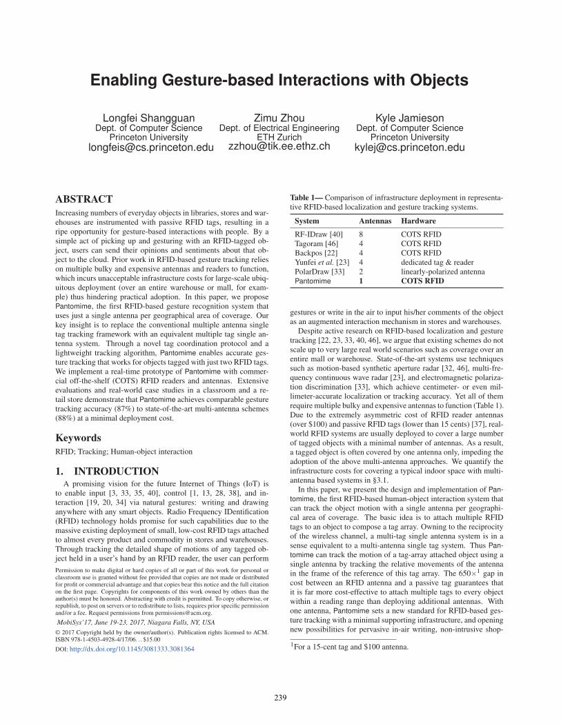
Figure 1— Hologram generated by an antenna array with different number of antennas and antenna spacing. The green square representsthe antenna, the purple dot indicates the ground truth location of the tag. n and s is the number of antennas and antenna spacing, respectively.
Table 2— Impact of coupling effect on phase readings.
Tag spacing (cm) 4.00 3.00 2.00 1.00 0.50Phase error (degree) 4.6 10.3 26.3 53.9 81.4
ping behavior identification, and instant commodity reviewing ser-vices.
A natural question arises over whether it is feasible to directlyapply the algorithms designed for multi-antenna single tag systemssuch as Angle-of-Arrival (AoA) [40, 45] and hologram based meth-ods [32, 46] to multi-tag single antenna systems by swapping theroles of antennas and tags. We argue that such a naive swappingwill lead to severe degradation in gesture tracking performance.Multi-antenna based approaches often make certain requirementson antenna quantity and spacing. However, it is often difficultto attach tag arrays to small object to fulfill these requirements.Specifically, AoA based schemes [40, 45] achieve a high angu-lar resolution by processing phase measurements collected from alarge antenna array. Attaching large numbers of tags on small ob-jects, e.g., a book spine, will result in closely spaced tags. A smalltag spacing then leads to significant coupling effects between adja-cent tags [32, 44], which can cause sizable errors in phase readings(Table 2), and consequently, unacceptable errors for object motiontracking. On the other hand, hologram-based methods [32, 46] de-mand both sufficient antenna spacing and number of antennas toyield satisfactory beam resolution (Figure 1). Yet it is unrealisticto simultaneously achieve large tag spacing and tag quantity on thesurfaces of small objects.
In addition to the difficulty to meet the requirements on tag spac-ing and tag population to yield a desirable resolution for gesturetracking, the adoption of tag arrays to each inventory object or re-tail item also brings a new challenge: low per-tag reading rate.By attaching two tags to each object within the reading range ofa reader antenna, the tag population also doubles. Since standardUHF RFID readers exploit the slotted ALOHA protocol [29] to in-terrogate RFID tags, a boosted tag population will cause significanttag reply collisions. Hence the reading rate (the number of success-ful tag interrogations per second) of each tag will drop by almosthalf, leading to sparsely-collected measurements that may even failto accurately track gestures performed at a normal speed. We quan-tify the impact of tag population on per-tag reading rate in §3.2.
Pantomime addresses the above challenges by incorporating (i) aMAC layer tag filtering algorithm to boost the reading rate of thosetags attached to the target object, and (ii) a novel Extended KalmanFilter (EKF) based tracking algorithm that tracks fine-grained ob-ject motions in a 2D plane with a limited number of tags attachedto an object. Specifically, Pantomime works as follows. It de-tects tag movement by examining the statistical distribution of their
phase readings. These moving tags are target tags for tracking.Pantomime then stops those stationary tags from responding to thereader, thereby reducing the RF traffic load and response collisionsto improve the reading rate of the target tags. As the object moves(so does the tag array attached to it), Pantomime tracks the relativelocation and the heading of the antenna in the frame of the refer-ence of the tag array. Finally, the relative locations of the antenna,together with a kinetic model based tracking result are fed into anEKF fusion model to further enhance the tracking accuracy.
Contributions and Roadmap. We design and implement the firstRFID-based human-object interaction system that enables users toinput their opinions and sentiments of an object through instantgestures. We demonstrate the potential widespread applicabilityof Pantomime for augmented interactions with two real-world casestudies: whiteboard handwriting tracking and retail-store item quer-ying (§2). Although attaching multiple tags on an object to inferthe object orientation has been studied [44], Pantomime is the firstsystem we are aware of that uses a tag array for gesture-based hu-man-object interaction. We present quantitative experimental mea-surements to demonstrate the antenna coverage problem and thelow tag reading rate issue in real-world scenarios (§3). Novel tech-niques introduced in §4 (Design) address these challenges, and thushave the potential to be applied to existing RFID infrastructure de-ployments without deploying additional hardware. We implementPantomime using COTS RFID devices (§5), evaluate both end-to-end performance and microbenchmarks in laboratory environments(§6), and compare it with two state-of-the-arts tracking systems:four-antenna Tagoram [46] and two-antenna PolarDraw [33]. Theresult shows that Pantomime achieves competitive tracking perfor-mance using a single antenna. We review related work in §7, dis-cuss limitations in §8 and conclude in §9.
2. CASE STUDYIn this section, we demonstrate the potential applicability of Pan-
tomime for gesture-based object interaction with two real-worldcase studies: whiteboard handwriting tracking and retail-store itemquerying.
2.1 Whiteboard handwriting trackingAlthough previous work [33, 40] has shown the feasibility of
handwriting tracking using multi-antenna RFID systems, this casestudy aims to demonstrate that handwriting tracking is viable with asingle antenna. Enabling handwriting tracking with minimal RFIDinfrastructure is essential to promote RFID-based sensing technolo-gies to smart homes, classrooms, and offices, where RFID systemshaven’t been pervasively deployed.
240

Tag array Recovered trajectoryFigure 2— Handwriting tracking: the antenna is placed near thepen for a better illustration. Tag spacing = 2.7cm.
Tag array
1.5m
Antenna
Figure 3— Retail store case study. Tag spacing = 5.4cm.
As an illustration, we deploy Pantomime in a classroom. We in-stall an antenna on top of a whiteboard and attach two passive RFIDtags to a marker pen as in Figure 2. A volunteer is then asked towrite letters at random on the whiteboard using the tagged markerpen. We plot the ground-truth trajectory of the marker pen and thetrajectory captured by Pantomime. In Figure 2, the red arrows showthe motion headings inferred by Pantomime, which are input intoour fusion algorithm to derive the final trajectory denoted by thegreen line. Compared with the ground-truth, the recovered letteris stretched and rotated due to tracking errors. However, the tra-jectory shape of this letter Z is well preserved and can be easilyrecognized. This result clearly demonstrates the viability of Pan-tomime to track the handwriting with high fidelity. In §6.3, wequantitatively evaluate the quality of the trajectories recovered byPantomime and compare it with the state-of-the-art multi-antennaRFID tracking systems.
2.2 Retail-store item queryingAcquiring customers’ opinions on groceries is desired for shop-
keepers to optimize the trading strategy and profit. While largeonline retailers e.g. Amazon can directly collect opinions of itemsvia online feedback systems, most small to medium sized offline re-tailers still lack effective methods to acquire customers’ opinion ongroceries. With proper incentive mechanisms such as coupons anddiscounts, customers might be motivated to provide instant and of-fline opinions on the goods if there is an interactive way to expresstheir opinions. This case study aims to demonstrate the viabilityof enabling RFID-based customer interactions, including offeringfeedback on the price and quality of daily goods, and reporting out-of-date items by performing the following in-air gestures with theitem held in hand:
♥: I like this item; ↓: Too expensive;?: Price unclear; O: Item (e.g., milk, bread) Out-of-date;
This gesture set is designed to include gestures consisting of bothstraight lines and curves. Figure 3 shows the deployment of Pan-tomime in a retail store, where passive RFID tags are attached to40 items, with two tags on each item. A volunteer is asked torandomly pick up the items and perform the four gestures above.
0 20 40 60 80 1000
50
100
X
Y
(cm)
(cm
)(c
m)
Y (c
m)
Figure 4— Recovered trajectory: ♥, ↓, ? and O.
20100
20
10
0
Y (
cm)
20100
X (cm)
20
10
020100
20
10
0
Figure 5— Recovered gesture when a user writes ♥ in the air usingretail items with different weights: the weight of the retail itemdecreases from the left to the right.
Figure 4 shows the recovered trajectories of the gestures. Appar-ently, the strokes in each gesture are warped or stretched due to thefact that the volunteer may change the item orientation unintention-ally during gesturing. An interesting finding is that the recoveredtrajectories are more easily recognized when performing gesturesholding a heavier item, as shown in Figure 5. A partial explana-tion might be that the volunteer will hold the item more steadilyif it is heavy, which helps to keep the orientation of the tag arrayunchanged. Note that we do not quantitatively evaluate the recogni-tion accuracy of these four gestures. Our aim is to demonstrate thatthe trajectories of such free-hand drawing-like gestures tracked byPantomime are recognizable by humans. Selecting a specific ma-chine learning algorithm for gesture recognition is out of the scopeof this work.
3. CHALLENGESThe previous section demonstrates potential applications of Pan-
tomime for emerging augmented interactions. In this section, weconduct two quantitative measurements on (i) antenna coverage and(ii) per-tag reading rate with different antenna and tag populationsettings to show (i) the difficulty of adopting multi-antenna basedtag tracking schemes with a cost-effective system deployment and(ii) the new challenge introduced by tag arrays.
3.1 Antenna crisisTo quantitatively measure the number of antennas needed to de-
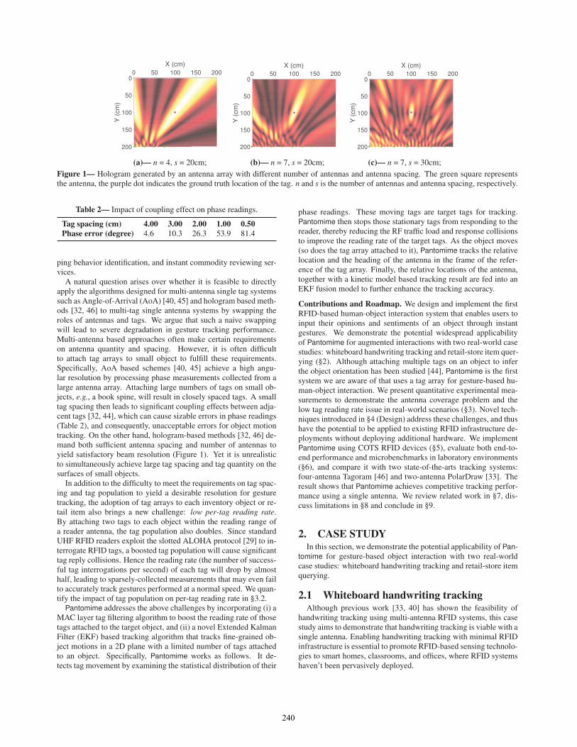
ploy existing RFID-based localization and tracking systems in med-ium-sized stores and warehouses, we conduct simulations in a 100mx 100m rectangular region. The region is divided into 1m x 1mblocks. We deploy different numbers of antennas in this region andcalculate the four-coverage ratio (Backpos [22] and Tagoram [46])and eight-coverage ratio (RF-IDraw [40]) of these blocks. Here ann-coverage ratio is defined as the percentage of blocks that can becovered by at least n reader antennas among all blocks. To make aconservative estimation of the number of antennas required for n-coverage, we set a wider beam-width (120◦) and a higher antennagain (20 dBm) of each antenna in our simulation. Figure 6 illus-trates the coverage ratio under different numbers of antennas. Wecan see that over 85% of the region is covered by at least one an-tenna when deploying 220 antennas. In contrast, 900 antennas are
241
0 200 400 600 800 1000
0.0
0.2
0.4
0.6
0.8
1.0C
over
age
Rat
io
Number of Antennas
One-coverageFour-coverageEight-coverage
Figure 6— Coverage ratio vs. Number of an-tennas (simulation).
3.5m
7m
Antenna onthe ceiling
ddd
Tag location
Antenna location
ddd
lllloocccaattiittt ooonndddddddd
dddddddddddd
AAA
ddddd
nnnnnnaaa ll
ddddddddddd
Figure 7— Coverage testing setup.
0.0
0.2
0.4
0.6
0.8
1.0true valuetheoretical value
2.01.51.00.5
Cov
erag
era
tio
antenna spacing (m)Figure 8— Four coverage ratio vs. antennaspacing d (experimental).
Table 3— The average readings (times/sec) of tag (T) and reader(R) under different tag population (n) settings.
n = 1 2 5 20 50 100
T 51.23 46.32 21.92 15.34 7.78 4.14R 51.23 92.64 109.6 306.79 388.84 413.52
required in order to provide a 85% four-coverage ratio. For eight-coverage, 1,000 antennas can only achieve around 54% coverageratio. The result clearly shows that the multiple antenna coveragerequirement will cause an “antenna crisis” – the number of anten-nas required grows dramatically with the expansion of the area tobe covered.
To better understand the antenna coverage problem in real-worlddeployment, we deploy multiple antennas in a laboratory to ex-amine the antenna coverage ratio. In this experiment, we mountfour circularly polarized antennas [16] on the ceiling 3 m above thefloor in a 3.5 m x 7 m laboratory, place an RFID tag in differentlocations in the room (white circles in Figure 7), and measure thenumber of antennas that can interrogate the tag. We estimate thecoverage ratio as the number of locations that are covered by fourantennas over different antenna spacing, and plot the results in Fig-ure 8. As shown, four antennas with a spacing d of 0.5 m yields a47% four-coverage ratio, which is moderately higher than the the-oretical value due to multi-path reflections. Given a spacing d of2 m, which resembles the antenna deployment in a real-world RFIDsystem [41], the four-coverage ratio drops dramatically to only 7%.In summary, Deploying a multi-antenna RFID tracking system inmalls, supermarkets, and warehouses will incur significant infras-tructure costs.
3.2 Low tag reading rateA high tag reading rate is essential to accurately track tag move-
ment. Insufficient reading rates are especially harmful to phase-based rfid tracking schemes because phase readings repeat from 0to 2π every wavelength, and a low reading rate will fail to capturethe consecutive phase changes when the tag moves fast, resulting inan ambiguity in the tag’s displacement. In gesture or handwritingtracking applications, a tagged object can move at a speed rangingfrom 0.5 m/s to 3.0 m/s [9]. Thus the tag should be read at a min-imal rate of 8 Hz to 46 Hz to avoid this phase ambiguity, given awavelength of 32 cm (UHF frequency 920.625 MHz).
Commercial RFID readers adopt Slotted ALOHA protocol [29]to interrogate tags within the reading range. Each tag randomlypicks a time slot to reply. A collision occurs when multiple tags re-ply in the same slot and the reader will fail to decode any of them.Although the allocated slots can scale to the tag population [46],collisions occur much more frequently for a large tag populationdue to the limited frame length [31], which decreases the per-tagreading rate. In this experiment, we examine the average tag read-
ing rate with different numbers of tags in an indoor laboratory en-vironment. Specifically, we place an RFID antenna 2 m away froma bookshelf to interrogate tags attached to the spine of books. Asshown in Table 3, the reader’s reading rate (R) increases signifi-cantly as tag population grows. However, the average per-tag read-ing rate ((T)) drops significantly from 46 Hz to around 4 Hz with100 tags. Such a low tag reading rate fails to meet the theoreticalminimum requirement for gesture tracking. As we further attachmultiple tags on each object, there will be more MAC contentionand more collisions, resulting in a much lower per-tag reading rate.
4. DESIGNThis section first introduces our proposed technique for boosting
the tag reading rate, followed by the virtual antenna tracking al-gorithm, and finally movement translation, the processing step thatoutputs the trajectory of the tagged object.
4.1 Boosting the tag reading rateThe basic idea to boost the reading rate of the tag array is to
make the reader interrogate these target tags only, instead of alltags within the reading range of the reader. Here target tags referto the tags on an object that a user holds in hand and performs ges-tures with. Non-target tags are the tags on other stationary objectsnearby. Thus the reading rate boosting scheme contains two steps:(i) identifying the target tags and (ii) blocking non-target tags fromresponding to the reader.
Inferring the target tags. To differentiate target and non-targettags, we leverage the intuition that the pick-up action will maketarget tag moving, hence leading to continuous phase changes ofthese target tags. In contrast, the non-target tags keeps stationaryand their phase reading remains. To validate the above intuition, weattach 40 tags to 20 books (two tags per book), and place an RFIDantenna 4 m away to interrogate the tags. The per-tag reading ratein this experiment is around 10 Hz. We collect phase measurementsunder four settings: a clear Line-Of-Sight (LOS) path between thetags and the antenna, people stands by to create reflection paths,people stands in between to block the LOS path, and people pickup a book to review. Figure 9 illustrates these testing setups.
For each testing case, we randomly pick up a tag and plot theirphase readings in Figure 10. As shown, the phase readings remainstable in clear LOS path condition. When the people walks to thebookshelf and generate a reflection path, we can see the phase read-ings of the stationary tag jumps from a stable level to another sta-ble level. Similar trend happens when the human walks to blockthe LOS path between the tag and the antenna. However, when thetag is picked up by the volunteer, we can see the phase readings ofthis tag change constantly across the whole cycle of [0, 2π]. Henceit is possible to distinguish the target tags by observing its phasechanging trend.
242

LOS blocked
Tag Tag
Antenna
Multipathhu
man
human
Antenna
Tag
AntennaFigure 9— Examining the motion-induced phase changes.
0.0 0.5 1.0 1.5 2.0 2.5 3.0
01234567
Phas
e(0
~2π)
Time (sec)
StationaryBlocking LOSMulti-pathPicking up
Figure 10— Phase pattern of tags under different motion states.
In Pantomime, we quantify the phase changing trend using anentropy metric. Low entropy correlates with narrow phase distri-bution likely from a stationary, non-target tag, while high entropyindicates a wider phase distribution possibly from a moving, targettag. Specifically, we split the range of phase readings [0, 2π] intoN bins with equal bin size. The bin size is empirically set to 0.5radians (see §6.2). Given a set of phase readings of tag i, let n j be
the number of phase readings within jth bin. We write the entropyof tag i as:
ei =− 1
lg(N −1)
N
∑j=1
p ji lg p j
i (1)
where p ji =
n j
∑Nk=1 nk
2. Pantomime then formulates the following hy-
pothesis test with H0 representing the hypothesis of a moving, tar-get tag and H1 of a stationary, non-target tag:{
H0 : ei ≥ γH1 : ei < γ, (2)
where γ denotes a predefined threshold. We conduct micro-bench-marks to test various γ settings and empirically set it to 0.7 (§6.2),which yields a satisfactory detection performance. As false posi-tives may still exist, Pantomime further filters out those target tagswhose siblings are detected as non-target tags. Here the siblings ofa tag represent the remaining tags in the same tag array.
Blocking the reply of non-target tags. After finding out the tar-get tags, our next step is to stop non-target tags from replying tothe reader, thereby reducing the amount of RF traffic and responsecollisions to improve the reading rate of the target tags. To achievethis goal, we manipulate the EPC-standard C1G2 low-level tag in-terrogation process [7]. As Figure 11 shows, at the beginning of
2we set lg p ji to 0 when p j
i = 0.
Select QueryCW CW
RN16 PC/XPC + EPC + CRC
ACK QueryRep
Reader
TagT4 T1 T2 T1 T2
Slot
Figure 11— Low-level reader to tag communication.
each inventory round (frame), the reader executes a SELECT com-mand to choose tags for inventory and access. After receiving thiscommand, the tags satisfying this selection criteria will enter theREADY state, indicating that they are ready to reply. Other tags willkeep silent (and not reply) until the end of this inventory round. Bysetting the SELECT criteria, we can thus stop the stationary tagsfrom replying. The default setting of SELECT is to let all tagsreply. In Pantomime, after detecting the target tags, we set the SE-LECT command to read the target tags alone by specifying the 96-bit EPC code of these tags. This is achieved by calling the functionsetC1G2TagInventoryMask of the C1G2Filter class provided by theLow-level Reader Protocol (LLRP) API.
After performing a gesture, the user may place the object backto the rack, resulting in a significant phase fluctuations due to theobject motions, and then relatively stable phase readings when theobject becomes stationary. Pantomime detects this state transitionby examining the variance of phase readings within every five sec-onds. A small variance indicates the object has been placed backon the rack, hence Pantomime will reconfigure the tag mask to letall tags reply. We test different variance threshold and set it to 0.3,which yields an empirically minimum false positive rate.
4.2 Virtual antenna trajectory trackingTo track the object motion using a single antenna, we track the
location changes of the antenna in the frame of the reference of thetag array and transform into a gesture trajectory in physical coordi-nates via motion translation. In Pantomime, we keep tracking therelative location of the antenna by estimating the change in tag-to-antenna distances. However, the accuracy of such ranging-basedtracking algorithm is undesirable due to multi-path reflection andthermal noises [46]. In Pantomime, we further improve the accu-racy of ranging-based tracking by incorporating a kinetic modeland an Extended Kalman Filter (EKF) fusion framework. In thefollowing parts, we first introduce our ranging-based tracking algo-rithm, and then describe how to improve its tracking accuracy withEKF model.
4.2.1 Pseudo-ranging tracking algorithmLet Pt = (xt ,yt) be the virtual position of the antenna at time t;
R j = (xRj ,yRj ) be the location of tag j in the frame of referenceof the tag array, which is known a prior. The distance from theantenna to tag j can be represented as:
d jt = ‖Pt ,R j‖=
√(xt − xR j )
2 +(yt − yR j )2 = λ
(θ j
t4π
)+ s j (3)
where θ jt is the phase reading of tag j at time t; s j is an unknown
distance offset. We assume the object moves within half a wave-length (≈16 cm) during consecutive tag readings.3 Accordingly,
3That is, no faster than 3 m/s given the reading rate of 46 Hz, whichcan be achieved after boosting the tag reading rate.
243

Tag arrayGround-truth
Antenna
Recovered trajectoryFigure 12— Recovering the trajectory of the moving cube basedon pseudo-ranging.
the virtual moving distance of the antenna during time t and t + 1can be computed as follows:
Δd jt+1 =
⎧⎪⎨⎪⎩
(θ jt+1 −θ j
t ) ·λ/(4π), if |θ jt+1 −θ j
t |< π(θ j
t+1 −θ jt −2π) ·λ/(4π), if θ j
t+1 −θ jt ≥ π
(θ jt+1 −θ j
t +2π) ·λ/(4π), if θ jt+1 −θ j
t ≤−π(4)
Now the distance between the reader antenna and each tag can beupdated as follows:
d jt+1 = ‖Pt+1,R j‖= d j
t +Δd jt+1 = d j
1 + s j +t+1
∑k=1
Δd jk (5)
In the above equation, we cannot compute d jt+1 due to the unknown
distance offset s j. However, s j is a constant value and will notchange throughout the object’s movement. Hence we omit s j anddefine the pseudo-distance between the antenna and tag j as fol-lows:
d jt+1 = d j
1 +t+1
∑k=1
Δd jk (6)
In the above equation, d j1 and ∑t+1
k=1 Δd jk can be computed using
Equation 3 and Equation 4, respectively. Thus we can estimate theantenna’s position (Pt ) at each time point and determine its virtualmoving trajectory in the frame of the reference of the tag array withat least two tags.
The pseudo-ranging tracking algorithm works in two steps: com-
puting the pseudo initial distance d j1 between the antenna and each
tag j, and then consecutively estimating the new location of the an-tenna as the object (antenna array) moves. Specifically, in each time
frame, the algorithm computes the virtual moving distance Δd jt+1 of
the antenna and updates the pseudo-distance d jt+1 between each tag
and the antenna. With d jt+1, the algorithm estimates the antenna’s
virtual location via trilateration.Figure 12 shows the trajectory of a letter U recovered by the
pseudo-ranging tracking algorithm. As shown, the recovered tra-jectory preserves the rough shape of the letter. However, there aresharp and abrupt discontinuities in the trajectory, especially at thecorners of the shape. This is because the location of the antennais estimated independently each time. Therefore, large location de-viation occurs during consecutive location estimates due to phasenoises and multi-path effect. To avoid unexpected discontinuitiesin the recovered trajectory, we further leverage heading informationto bound the deviation of successive location estimates.
Antenna heading inference. In Figure 13(b), suppose the antennamoves from position A to B within two tag readings. Since the sam-pling rate of the tag is high, hence we know |AB| |AT2|. Thus it is
T2
A B
B2
C
T2T1
T3
B3
B2
B1
T1T2T3
A CB
(a) (b) (c)
A B
Figure 13— An illustration of the antenna heading inference. Theantenna virtually moves from point A to point B and our algorithmcontinuously tracks the antenna heading during its virtual move-ment.
reasonable to approximate the antenna’s displacement along the ra-dial direction |AB2| with Δd. On the other hand, since the antenna’sposition A is estimated through the position-velocity model (de-
scribed later), it is thus feasible to determine the heading of ∠−−→AB2
as well. Taking one step further, we can infer the displacement and
the heading of ∠−−→AB1 and ∠−−→AB3 in a similar way (as shown in Fig-ure 13(c)), and finally determine the antenna heading by summingup these vectors.
4.2.2 Kinetic model based tracking algorithm
Position-velocity model. We employ constant acceleration model-[21] to characterize the hand motion. So the antenna movementsuits this model as well. In the frame of reference of the tag array,consider the discrete time model: let T be the window size in ms.Within each window, the state of the antenna can be characterizedby its location P = [xt ,yt ], velocity V = [xt , yt ] and accelerationA = [xt , yt ]:
Xt = [P,V ,A] = [xt , xt , xt ,yt , yt , yt ] (7)
The state transition model can be written as:
Xt+1 = f (Xt)+Wt = AXtT +Wt
=
⎡⎢⎢⎢⎢⎢⎣
1 T T 2/2 0 0 00 1 T 0 0 00 0 1 0 0 0
0 0 0 1 T T 2/20 0 0 0 1 T0 0 0 0 0 1
⎤⎥⎥⎥⎥⎥⎦ ·
⎡⎢⎢⎢⎢⎢⎣
xtxtxtytytyt
⎤⎥⎥⎥⎥⎥⎦+
⎡⎢⎢⎢⎢⎢⎣
T 2/2 0T 01 0
0 T 2/20 t0 1
⎤⎥⎥⎥⎥⎥⎦ ·
[nx
tny
t
]
where A models the state transition of the antenna from window tto t + 1. Vector Wt takes thermal noise into account, which fol-lows normal distribution with zero mean and covariance matrix Qt :Wt ∼ N (0,Qt). With the antenna heading and the position-veloc-ity model, it is viable to track the virtual movement of the antennain the frame of reference of the tag array, and accordingly the move-ments of the tagged object. However, since the acceleration of thehand gesture may change abruptly, the constant acceleration modelfails to accurately characterize the shape of the virtual antenna mo-tion.
4.3 Fusion AlgorithmAs pointed out previously, the ranging-based method can recover
the rough shape of the virtual antenna movement yet fail to charac-terize the trajectory smoothly. Conversely, the kinetic model basedmethod could track the trajectory smoothly, yet fail to accurately
244

characterize its shape with natural hand movements. We thus lever-age the Extended Karman Filter (EKF) model to fuse the trackingresults of these two tracking algorithms for a better result.
Observation. Let N be the number of tags attached to the object.The observation function is defined as:
Yt+1 = h(Xt+1)+Vt+1
=
⎡⎢⎢⎢⎣‖Pt+1,R1‖‖Pt+1,R2‖
...‖Pt+1,RN‖
⎤⎥⎥⎥⎦+Vt+1 =
⎡⎢⎢⎢⎣
d1t +Δd1
t+1
d2t +Δd2
t+1...
dNt +ΔdN
t+1
⎤⎥⎥⎥⎦+Vt+1
(8)
where Vt+1 is the ranging errors due to phase noises. We empiri-
cally set Vt+1 to 110 ·mean(Δd j
t ), where mean(Δd jt ) is the average
value of the change of the distance between the antenna and eachtag. h(.) is a non-linear function that relates observations and states.
EKF-based Motion Tracking. The EKF-based fusion algorithmconsists of three steps: linearization, prediction and updating. Wedetail them in turn in the following parts.Linearization. In Equation 8, the nonlinear function h(.) can belinearized about X0 as follows:
Yt −Yt−1 = HtΔXt +Vt (9)
where Ht is the Jacobian matrix of h(.) with respect to Xn.Predicting phase. Given the estimate Xt|t of Xt , the predicted state
Xt+1|t is calculated as:
Xt+1|t = Ft Xt|t (10)
where Ft =∂ f∂X |X t|t is the Jacobian matrix of f (.). The prediction
error covariance matrix Pt+1|t associated to the predicted state es-
timation Xt+1|t is evaluated from the previous estimate Pt|t :
Pt+1|t = Ft Pt|tFTt +Qt (11)
The predicted measurement is then computed as follows:
Y t+1|t = h(Xt+1|t)+Vt+1 (12)
Updating phase. Once the system acquires new phase readings attime t+1, it computes the difference between the measurement andthe predicted measurement as follows:
γ t+1 = Yt+1 − Y t+1|t (13)
with the covariance:
St+1 = Ht+1Pt+1|tHTt+1 +Rt+1 (14)
where Ht+1 =∂h∂X |X t+1|t is the Jacobian matrix of the state transition
function f (.) with respect to the predicted state Xt+1|t . After that,it computes the EKF gain as follows:
Kt+1 = Pt+1|tHt+1(St+1)−1 (15)
Finally, the algorithm computes a posterior state estimate Xt+1|t+1
and the corresponding covariance matrix Pt+1|t+1 by correcting the
priori state estimate Xt+1|t and Pt+1|t :
Xt+1|t+1 = Xt+1|t +Kt+1γt+1 (16)
Pt+1|t+1 = (IN −Kt+1Ht+1)Pt+1|t (17)
0 2 4 6 8 10 1201234567
Phas
e (0
~2)
Time (s)
Tag 1 Tag 2
0 2 4 61.61.8
22.22.42.6
Sample
Pha
se
Figure 14— Phase readings of two tags attached to an object thathas been picked up for gesturing.
Targetdetection
RFIDreader
SELECT targeting tag
Y
N
Dynamicsegment
Averaging
Phase
Delete
Trackingengine
MAC layer Middleware App layer
App 01
App 02
App N
Figure 15— System workflow of Pantomime.
4.4 Motion TranslationLet S = {P1,P2, ...,Pt} be the recovered trajectory of the antenna
in the frame of reference of the tag array and S′ be the real trajectoryof the object in the frame of the reference of the physical world. Wecan recover S′ by rotating S by π:
S′ = S ·[
cosπ −sinπsinπ cosπ
](18)
5. IMPLEMENTATIONSo far we have provided the algorithmic basis of how Pantomime
works. This section describes its implementation.
RF-sensing module. The hardware of the RF-sensing module con-sists of three parts: an ImpinJ Speedway R420 RFID reader [11], anRFMAX indoor RFID antenna [16], and multiple Avery DennisonAD-227m5 UHF passive RFID tags [5]. The reader interrogatesRFID tags and sends phase readings to a Lenovo ThinkCentre PCfor processing.
Frontend software. Figure 15 shows the workflow of Pantomime.The reader interrogates tags using the Low Level RFID Protocol(LLRP) API. We implement the reading rate control function inthe MAC layer. Once the target tags are detected, the reader stopsother stationary tags from replying in the following frames. Thephase readings of target tags are then delivered to the middlewarelayer for segmentation and tracking. The output of the middlewarelayer is the trajectory of the antenna in the frame of the reference ofthe tag array, which can be integrated to various applications (aftertrajectory translation) such as virtual touch screen and in-air bookreviewing. The software is implemented in C# and it tracks theobject in real-time.
Dynamic segmentation. To minimize the noises and interference,Pantomime segments phase streams into windows and uses the av-erage phase in each window as the input of the tracking engine. Thewindow size is critical to our system. If it is too small, Pantomimeneeds to frequently feed the phase readings to the tracking engine,leading to significant computational overhead. If the window size
245

Tag array
Moving patternword
Tag array
Figure 16— Experimental setup: We construct tag arrays by at-taching multiple tags to a food package and a plastic cube, andmove them along trajectories printed on paper.
Tag array
(a) (b) (c)Figure 17— Different layout of tag arrays.
is too large, the phase changes induced by motions are likely to av-erage out, resulting in tracking errors. Either case will degrade thesystem performance.
In Pantomime, we design a dynamic segmentation mechanism.It is based on the following finding: if the object moves slowly, thephase will change slowly and smoothly, and we can safely expandthe window size. If the object moves fast, the phase will changerapidly, we need to reduce the window size to preserve the detail ofthe phase profile. Specifically, Pantomime updates the window sizeas follows:
if vt - vt−1 < -vT H & Wt + Wa < Wmax thenWt+1 ← Wt + Wa;
else if vt - vt−1 > vT H & Wt - Wa > Wmin thenWt+1 ← Wt - Wa;
elseWt+1 ← Wt ;
end ifwhere Wα is a constant to control the window length; vt is the mov-ing speed of the tag in the time window t; vT H is the moving speedthreshold. Within each window, the window size updates until itsurpasses or falls below the maximum and minimum window sizeWmax and Wmin, respectively. We test a wide range of parametersettings, and empirically set vT H , initial window size W , Wα , Wmaxand Wmin to 0.1 m/s, 40 ms, 20 ms, 200 ms and 20 ms, respectively.
6. EVALUATIONIn this section, we present the experimental evaluation results
of Pantomime, starting with the experimental methodology, micro-benchmarks and ending with field studies.
6.1 Experimental methodologyWe attach RFID tags to both a food package and a plastic cube
to form a tag array and move the array along printed trajectories.The trajectories cover different English letters, words (with differ-ent lengths) and paths (see Figure 16).
We use recognition accuracy to quantify the performance of Pan-tomime. The recognition accuracy is defined as the fraction ofcorrectly recognized hand-written letters/words over total numberof hand-written letters/words. For letter recognition, we use Lip-iTk [10], an open-source handwriting recognition toolkit.
Table 4— FP/FN rate under different γ and bin size settings.
Bin size0.5 (rad) 1 1.5 2
0.1 0.72/0.01 0.72/0.01 0.72/0.01 0.81/0.030.3 0.51/0.01 0.51/0.01 0.53/0.02 0.74/0.05
γ 0.5 0.21/0.03 0.21/0.03 0.21/0.04 0.43/0.060.7 0.03/0.03 0.06/0.03 0.06/0.07 0.14/0.090.9 0.02/0.06 0.02/0.06 0.02/0.10 0.06/0.12
6.2 MicrobenchmarksIn these microbenchmark experiments, we answer the following
questions:
1. How do bin size and γ affect tag detection?
2. How does tag reading rate affect tracking performance?
3. How does array size affect tracking performance?
4. How does array layout affect tracking performance?
5. Does the EKF fusion algorithm improve tracking accuracy?
Configuring bin size and γ . We first perform a sensitivity analy-sis, examining how the bin size and the threshold γ affect the tar-geting tag detection accuracy. In this experiment, two volunteersrandomly pick up a book from 20 tagged books. Each experimentis repeated 50 times, and we get 100 phase series in total. We alsocollect 100 phase series of those stationary tags, whose wirelesslinks are blocked or reflected by nearby humans. We then vary thebin size and γ to find an appropriate setting. Table 4 summarizes theFalse Positive (FP) rate and False Negative (FN) rate with differentthe bin size and γ . The desired parameter setting should minimizeboth the FP and FN rates. Suggested by the experimental result, weset the bin size and γ to 0.5 rad and 0.7, which optimize the overalldetection performance.
Impact of tag reading rate. We then examine the impact of thetag reading rate. In this experiment, we randomly pick 10 lettersfrom 26 English letters and let a volunteer write these letters usingthe two-tag array cube (see Figure 16). We change the tag pop-ulation in the antenna’s reading range to control the tag readingrate. Figure 18 shows the recognition accuracy. As expected, therecognition accuracy is sensitive to the average tag reading rate. Itachieves an accuracy below 20% when the reading rate is around8 Hz, and then jumps to around 80% when the average per-tag read-ing rate is 31 Hz. In contrast, Pantomime achieves constantly highrecognition accuracy after boosting the tag reading rate, with theaccuracies all above 87%, which verifies the efficacy of our tagreading rate boosting protocol.
Impact of array layout. We then examine the impact of the arraylayout. As shown in Figure 17, we attach four tags to a plastic cube,forming a rectangle array and a linear array. We randomly choose10 letters from the English alphabet, and invite a volunteer to writeeach letter 10 times using these two different tag-array. The let-ter recognition accuracy is shown in Table 5. As the result shows,Pantomime achieves 92% letter recognition accuracy with the rect-angle array. The recognition accuracy drops slightly to 86% withthe linear array. The performance gap here indicates that the natureof sparse tag distribution in the rectangle array helps to improve thetracking accuracy.
Impact of array size. We next examine the impact of the arraysize. Similar to previous experiments, we invite a volunteer to write
246

0
0.2
0.4
0.6
0.8
1
8 15 22 31Reco
gniti
on a
ccur
acy
Average reading rate (Hz)Figure 18— Impact of reading rate.
Table 5— Impact of Array layout.
Rectangle array Linear arrayRecognition accuracy 92% 86%
10 letters using a linear tag array of size 2 to 5. Figure 19 showsthe recognition accuracy. As we see, the recognition accuracy in-creases as we attach more tags to the cube. This is because com-pared with a small tag array, the large tag array can help average outranging noise. However, the performance gap between the small ar-ray (e.g., two-tag array) and the larger one (e.g., five-tag array) isconfined to a small range (below 5% in the experiment), indicatingthat the large array marginally improves tracking accuracy.
0
0.2
0.4
0.6
0.8
1
2 3 4 5Reco
gniti
on a
ccur
acy
Number of tags in the tag arrayFigure 19— Impact of array size.
Gain of fusion algorithm. This experiment validates the gain ofthe EKF fusion algorithm for gesture tracking. Four volunteers areasked to use the two-tag array to write 10 letters randomly chosenfrom the 26 English letters. These written letters are then put intothe LipiTk for letter recognition. The result is shown in Figure 20.Pantomime achieves a relatively stable performance over all fourvolunteers, with a maximum and minimum recognition accuracyof 87% and 83%, respectively. In contrast, when solely running thepseudo ranging-based tracking algorithm, Pantomime achieves un-desirable performance over the four volunteers, with a maximumrecognition accuracy of around 56%. This result demonstrates thatthe EKF fusion algorithm significantly improves the tracking accu-racy.
6.3 Field studyWe conduct field studies in a laboratory environment. In the field
study, we attach two tags to a food package to form a stylus (seeFigure 16). A volunteer is asked to use this light-weighted stylus
0
0.2
0.4
0.6
0.8
1
1 2 3 4Reco
gniti
on a
ccur
acy
Group
With EKF Without EKF
Figure 20— Examine the EKF gain.
to write given characters. We are of particular interest in answeringthe following questions:
1. Is Pantomime robust to different moving patterns?
2. Is Pantomime resilient to multi-path effect?
3. Does tag-to-reader distance affect the tracking accuracy?
4. Does backing material affect the tracking accuracy?
5. How does Pantomime perform compared with other state-of-the-art systems?
6. Can we adapt Pantomime to multi-antenna settings?
Robustness to moving patterns. We first examine whether Pan-tomime can successfully track different kinds of trajectories for fu-ture drawing applications. These trajectories include three kindsof fundamental line drawings [36]: straight lines, wave lines, andjagged lines, as shown in Figure 16. Figure 21 shows the recoveredtrajectories. As shown, the recovered wave line and jagged line arenot self-symmetric due to tracking errors. However, each of themstill preserves its unique line pattern, making them distinguishableto human beings. Also, we can see the recovered straight line isstill smooth despite deviating from its ground truth at small scale.
Figure 21— Wave line, jagged line, and straight line, as outputs ofPantomime.
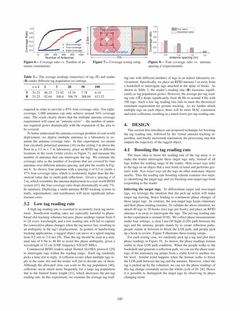
We further show a sample of the recovered trajectory of lettersM o b i S y s in Figure 22. The recovered trajectories of letters oand s are quite smooth, manifesting that Pantomime is capable ofcapturing the continuously moving heading changes. The detailedshapes of these seven letters are well preserved.
Resilience to multi-path reflections. We then examine the impactof both static and dynamic multi-path on the tracking performance.
247
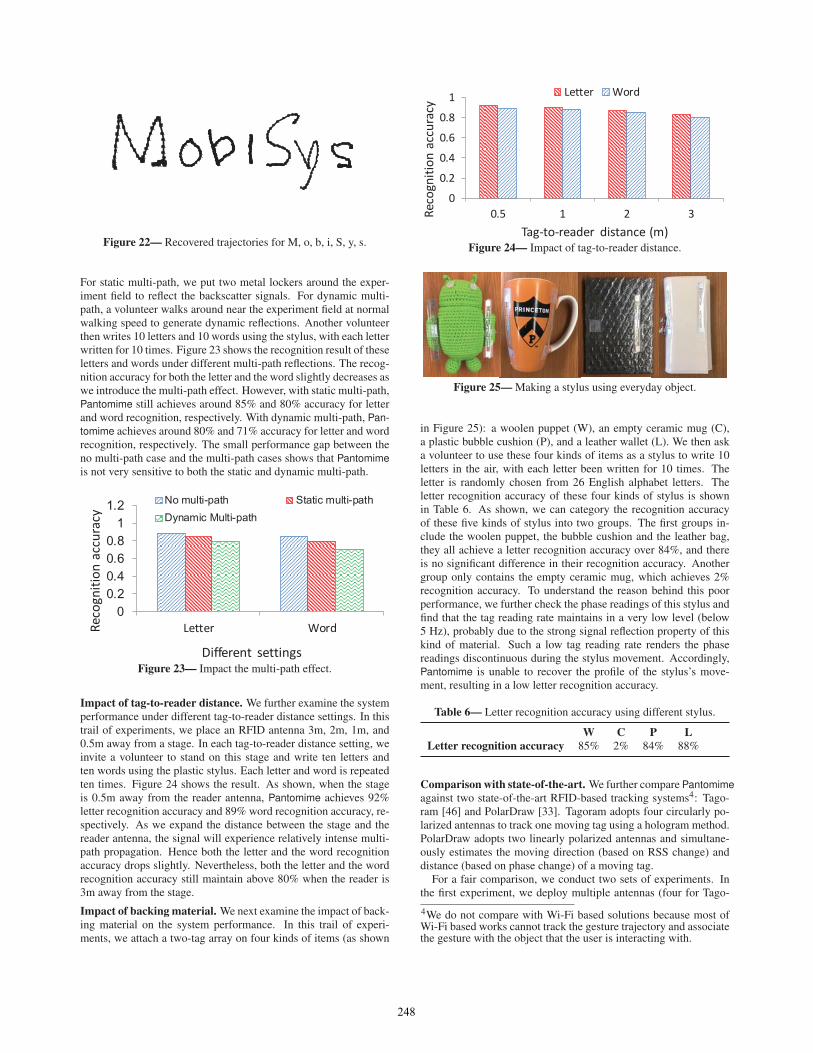
Figure 22— Recovered trajectories for M, o, b, i, S, y, s.
For static multi-path, we put two metal lockers around the exper-iment field to reflect the backscatter signals. For dynamic multi-path, a volunteer walks around near the experiment field at normalwalking speed to generate dynamic reflections. Another volunteerthen writes 10 letters and 10 words using the stylus, with each letterwritten for 10 times. Figure 23 shows the recognition result of theseletters and words under different multi-path reflections. The recog-nition accuracy for both the letter and the word slightly decreases aswe introduce the multi-path effect. However, with static multi-path,Pantomime still achieves around 85% and 80% accuracy for letterand word recognition, respectively. With dynamic multi-path, Pan-tomime achieves around 80% and 71% accuracy for letter and wordrecognition, respectively. The small performance gap between theno multi-path case and the multi-path cases shows that Pantomimeis not very sensitive to both the static and dynamic multi-path.
Letter WordReco
gniti
on a
ccur
acy
Different settingsFigure 23— Impact the multi-path effect.
Impact of tag-to-reader distance. We further examine the systemperformance under different tag-to-reader distance settings. In thistrail of experiments, we place an RFID antenna 3m, 2m, 1m, and0.5m away from a stage. In each tag-to-reader distance setting, weinvite a volunteer to stand on this stage and write ten letters andten words using the plastic stylus. Each letter and word is repeatedten times. Figure 24 shows the result. As shown, when the stageis 0.5m away from the reader antenna, Pantomime achieves 92%letter recognition accuracy and 89% word recognition accuracy, re-spectively. As we expand the distance between the stage and thereader antenna, the signal will experience relatively intense multi-path propagation. Hence both the letter and the word recognitionaccuracy drops slightly. Nevertheless, both the letter and the wordrecognition accuracy still maintain above 80% when the reader is3m away from the stage.
Impact of backing material. We next examine the impact of back-ing material on the system performance. In this trail of experi-ments, we attach a two-tag array on four kinds of items (as shown
0
0.2
0.4
0.6
0.8
1
0.5 1 2 3Reco
gniti
on a
ccur
acy
Tag-to-reader distance (m)
Letter Word
Figure 24— Impact of tag-to-reader distance.
Figure 25— Making a stylus using everyday object.
in Figure 25): a woolen puppet (W), an empty ceramic mug (C),a plastic bubble cushion (P), and a leather wallet (L). We then aska volunteer to use these four kinds of items as a stylus to write 10letters in the air, with each letter been written for 10 times. Theletter is randomly chosen from 26 English alphabet letters. Theletter recognition accuracy of these four kinds of stylus is shownin Table 6. As shown, we can category the recognition accuracyof these five kinds of stylus into two groups. The first groups in-clude the woolen puppet, the bubble cushion and the leather bag,they all achieve a letter recognition accuracy over 84%, and thereis no significant difference in their recognition accuracy. Anothergroup only contains the empty ceramic mug, which achieves 2%recognition accuracy. To understand the reason behind this poorperformance, we further check the phase readings of this stylus andfind that the tag reading rate maintains in a very low level (below5 Hz), probably due to the strong signal reflection property of thiskind of material. Such a low tag reading rate renders the phasereadings discontinuous during the stylus movement. Accordingly,Pantomime is unable to recover the profile of the stylus’s move-ment, resulting in a low letter recognition accuracy.
Table 6— Letter recognition accuracy using different stylus.
W C P LLetter recognition accuracy 85% 2% 84% 88%
Comparison with state-of-the-art. We further compare Pantomimeagainst two state-of-the-art RFID-based tracking systems4: Tago-ram [46] and PolarDraw [33]. Tagoram adopts four circularly po-larized antennas to track one moving tag using a hologram method.PolarDraw adopts two linearly polarized antennas and simultane-ously estimates the moving direction (based on RSS change) anddistance (based on phase change) of a moving tag.
For a fair comparison, we conduct two sets of experiments. Inthe first experiment, we deploy multiple antennas (four for Tago-
4We do not compare with Wi-Fi based solutions because most ofWi-Fi based works cannot track the gesture trajectory and associatethe gesture with the object that the user is interacting with.
248
Tagoram PolarDraw PantomineReco
gniti
on A
ccur
acy
Different algorithmsFigure 26— Recognition accuracy achieved by different system inMulti-antenna settings.
ram and two for PolarDraw) to track handwriting and compare therecognition accuray with Pantomime. Figure 26 shows the result.With four antennas, Tagoram achieves an average recognition ac-curacy of 92%. While for the two-antenna PolarDraw, the averagerecognition accuracy is 88%. Our single antenna based Pantomimeachieves an average recognition accuracy 87%, which is slightlylower than Tagoram but similar to PolarDraw. With natural lan-guage processing techniques like [25], we believe recognition ac-curacy can be improved even further.
In the second experiment, we use one antenna and attach mul-tiple tags (four for Tagoram and Two for PolarDraw) to the foodpackage to compose a multi-tag single antenna tracking system.We then implement Tagoram and Polardraw to track the virtualmovement of the antenna in the frame of the reference of the tagarray. The recovered trajectories are rotated and fed into the letterrecognition software. Figure 27 shows the recognition result. Asexpected, Tagoram achieves inferior performance due to the lowbeam resolution. PolarDraw’s performance also degrades becauseof the limited array spacing and the stiff writing style (i.e., writ-ing without rotation). In contrast, Pantomime achieves consistentlyhigh recognition accuracy (88%), which is superior to both Tago-ram and PolarDraw.
Tagoram PolarDraw PantomimeReco
gniti
on A
ccur
acy
Different algorithmsFigure 27— Recognition accuracy achieved by different system inMulti-tag settings.
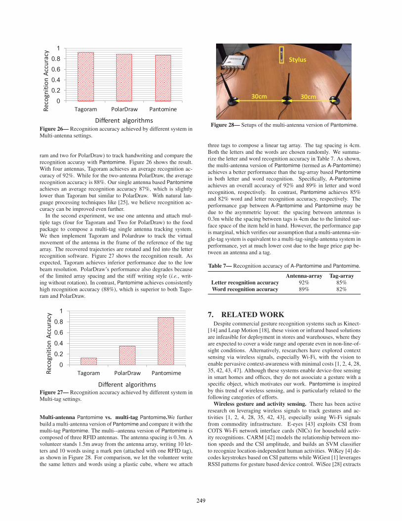
Multi-antenna Pantomime vs. multi-tag Pantomime.We furtherbuild a multi-antenna version of Pantomime and compare it with themulti-tag Pantomime. The multi--antenna version of Pantomime iscomposed of three RFID antennas. The antenna spacing is 0.3m. Avolunteer stands 1.5m away from the antenna array, writing 10 let-ters and 10 words using a mark pen (attached with one RFID tag),as shown in Figure 28. For comparison, we let the volunteer writethe same letters and words using a plastic cube, where we attach
30cm 30cm
Stylus
Figure 28— Setups of the multi-antenna version of Pantomime.
three tags to compose a linear tag array. The tag spacing is 4cm.Both the letters and the words are chosen randomly. We summa-rize the letter and word recognition accuracy in Table 7. As shown,the multi-antenna version of Pantomime (termed as A-Pantomime)achieves a better performance than the tag-array based Pantomimein both letter and word recognition. Specifically, A-Pantomimeachieves an overall accuracy of 92% and 89% in letter and wordrecognition, respectively. In contrast, Pantomime achieves 85%and 82% word and letter recognition accuracy, respectively. Theperformance gap between A-Pantomime and Pantomime may bedue to the asymmetric layout: the spacing between antennas is0.3m while the spacing between tags is 4cm due to the limited sur-face space of the item held in hand. However, the performance gapis marginal, which verifies our assumption that a multi-antenna-sin-gle-tag system is equivalent to a multi-tag-single-antenna system inperformance, yet at much lower cost due to the huge price gap be-tween an antenna and a tag.
Table 7— Recognition accuracy of A-Pantomime and Pantomime.
Antenna-array Tag-arrayLetter recognition accuracy 92% 85%Word recognition accuracy 89% 82%
7. RELATED WORKDespite commercial gesture recognition systems such as Kinect-
[14] and Leap Motion [18], these vision or infrared based solutionsare infeasible for deployment in stores and warehouses, where theyare expected to cover a wide range and operate even in non-line-of-sight conditions. Alternatively, researchers have explored contextsensing via wireless signals, especially Wi-Fi, with the vision toenable pervasive context-awareness with minimal costs [1, 2, 4, 28,35, 42, 43, 47]. Although these systems enable device-free sensingin smart homes and offices, they do not associate a gesture with aspecific object, which motivates our work. Pantomime is inspiredby this trend of wireless sensing, and is particularly related to thefollowing categories of efforts.
Wireless gesture and activity sensing. There has been activeresearch on leveraging wireless signals to track gestures and ac-tivities [1, 2, 4, 28, 35, 42, 43], especially using Wi-Fi signalsfrom commodity infrastructure. E-eyes [43] exploits CSI fromCOTS Wi-Fi network interface cards (NICs) for household activ-ity recognitions. CARM [42] models the relationship between mo-tion speeds and the CSI amplitude, and builds an SVM classifierto recognize location-independent human activities. WiKey [4] de-codes keystrokes based on CSI patterns while WiGest [1] leveragesRSSI patterns for gesture based device control. WiSee [28] extracts
249

Doppler frequency shifts from Wi-Fi signals for arm gesture recog-nition. WiDraw [35] tracks hand motions by measuring angle-of-arrival (AoA) extracted from CSI. Although these systems enabledevice-free sensing for context-awareness in smart homes and of-fices, they do not associate a gesture with a specific RFID-taggedobject, as Pantomime does.
RFID-based gesture and activity sensing. The ubiquitous de-ployment of RFID tags makes them promising for interactions andactivity recognition with everyday objects. TagFall [30] leveragesRFID for fall detection. FEMO [8] extracts Doppler signatures toclassify and assess the quality of free-weight activities by attachingRFID tags to dumbbells. ShopMiner [34] harnesses the phase pat-terns of RFID tags attached to garments to infer shopping behaviorsin physical clothing stores. IDSense [20] combines RSSI and phasepatterns of RFID tags to identify touching and moving events of thetagged objects. PaperID [19] extract features from RSSI, phase andreading rate for gesture recognition on traces printed or drawn onpaper with conductive ink. AllSee [13] powers an RFID-like ges-ture recognition interface by backscattering ambient wireless sig-nals. While some of them [13, 19] have enabled gesture recognitionwith a single antenna, they rely on machine learning to recognizea predefined set of gestures. Pantomime is complementary in thatPantomime outputs the trajectory shapes of object motions, whichcan be further fed into different machine learning algorithms forscalable gesture recognition and other applications such as hand-writing tracking and drawing. Pantomime is most close to workson RFID-based gesture tracking [33, 40]. RF-IDraw [40] exploitscarefully designed antenna arrays to track the AoA of finger mo-tions. PolarDraw [33] leverages the polarization mismatch of twolinearly polarized antennas to track handwriting. Pantomime ad-vances the area by achieving comparable gesture tracking perfor-mance using one single antenna, thus yielding the minimal costsfor RFID-based gesture tracking.
RFID-based localization and tracking. LANDMARC [26] isthe first active RFID based localization scheme by deploying an-chor tags. PinIt [39] exploits the multi-path profile of RFID tagsattached to books to locate these tagged books in NLOS environ-ments. The adoption of anchor tags for profile matching incurs highcost and the decimeter localization accuracy is unfit for fine-grainedgesture tracking. Other works leverage Synthetic Aperatures Radar(SAR) or Inverse SAR (ISAR) to track RFID tags at centimeter-scale accuracies. In [24], the authors introduce a hologram-basedscheme to track a moving tag on a transponder. In [27], the authorsleverage the tag mobility and adopt ISAR to localize an RFID tag.Tagoram [46] introduces a multi-antenna based hologram methodto localize and track tag motion trajectories with error centimeteraccuracies. However, all these SAR-based schemes require multi-ple bulky and expensive RFID antennas to function, impeding theirdeployment in stores and warehouses. In addition, both SAR andISAR based schemes track the RFID tag by calculating its positionfor each time point. Conversely, Pantomime tracks the tag arrayvia the changes of the tag-to-reader distances without pinpointingits absolute position. Tagyro [44] attaches multiple tags on an ob-ject to track its 3D orientation using differential phase-based holo-gram. However, it does not consider the limited tag reading andinsufficient antenna coverage issues. Pantomime is designed forthe fine-grained gesture tracking and we show that hologram-basedmethods fail to achieve this goal due to the space limitation of theobject and the antenna crisis.
8. DISCUSSIONWe discuss limitations and opportunities for improvement.Identifying the beginning of the gesture. Pantomime needs to
detect the beginning of the gesture in the phase stream for gesturetracking. The technique we propose is based on instructing usersto hold the tagged object for a short period before performing agesture, which results in relatively stable phase readings that natu-rally separate the pick-up action and the gestures (see Figure 14).Similar to the activity detection algorithm used in [8], Pantomimeuses K-L divergence [15] to identify these short resting periods,and tracks the gesture hereafter.
Support for multiple users. Our current prototype supports sin-gle user gesture tracking per antenna, because when a user performsgestures in front of an antenna, Pantomime blocks all the remainingtags within its reading range from replying. Pantomime can supportmultiple users by letting the reader interrogate both target and non-target tags at different sampling rates, e.g., sampling all target tagsat a high frequency, yet sampling only one tag attached to each ofthe remaining objects at a lower rate for multiple user detection.However, this requires modifications of the MAC protocol and weleave it for future work.
Trade-off between multi-tag and multi-antenna systems. Re-cent research on MIMO RFID readers [17] has lowered down thecost of a multi-antenna system, yet an RFID antenna can still cost100 USD, more than 600 times the cost of an RFID tag (15 cent).Thus the additional cost to deploy 3 more antennas to support four-coverage ratio can support attaching a 2-tag array to around 2000objects. Since the typical effective reading area of a ceiling-mountedRFID antenna is about 10m2, it is reasonable that there will befewer than 1500 objects placed on shelves in stores and warehouseswithin this effective reading area. Therefore, a multi-tag systemlike Pantomime is a more cost-effective alternative to current multi-antenna solutions. Multi-tag solutions also have the advantages ofimproving the item detection probability [6], which is desirablein store and warehouse management to reduce potential financiallosses.
Practicality of hardware solutions. Note that Pantomime servesas a proof-of-concept to show the benefits of attaching multipletags on each object. Our aim is to provide a new object interac-tion mechanism for stores and warehouses, where the adoption oflow-cost, widely accessible infrastructure is essential. In principle,recent research on multi-antenna RFID tags [12] is also applicablein our scenarios with customized MAC protocols, and will avoidthe challenge of reading rate. We envision the future commercial-ization of multi-antenna RFID tags will further decrease the cost ofmulti-tag systems like Pantomime.
9. CONCLUSIONIn this paper, we present the design, implementation and evalu-
ation of Pantomime, a gesture tracking system with a single RFIDantenna. Through both comprehensive experiments and real-worldcase studies, we demonstrate that Pantomime achieves compara-ble gesture tracking accuracy to the state-of-the-art multi-antennamethods, showing the potential to support various gesture-basedobject interactions with a minimal deployment cost. In the futurewe plan to extend Pantomime to multi-user cases and deploy it inan entire warehouse/mall for large-scale and long-term studies.
AcknowledgementsWe thank our shepherd Shyam Gollakota and the anonymous re-viewers for their helpful feedback. This material is based uponwork supported by the National Science Foundation under GrantNo. 1617161.
250

References[1] H. Abdelnasser, M. Youssef, K. A. Harras. Wigest: A
ubiquitous wifi-based gesture recognition system.INFOCOM, 2015.
[2] F. Adib, Z. Kabelac, D. Katabi, R. Miller. 3D Tracking viabody radio reflections. NSDI, 2014.
[3] S. Agrawal, I. Constandache, S. Gaonkar,R. Roy Choudhury, K. Caves, F. DeRuyter. Using mobilephones to write in air. MobiSys, 2011.
[4] K. Ali, A. X. Liu, W. Wang, M. Shahzad. Keystrokerecognition using WiFi signals. MobiCom, 2015.
[5] Avery-Dennison UHF RFID inlay AD-227m5. Web page.
[6] L. Bolotnyy, S. Krize, G. Robins. The practicality ofmulti-tag rfid systems. IWRT, 2007.
[7] EPC radio-frequency identity protocols class-1 generation-2uhf rfid protocols for communications at 860 MHz - 960MHz. .
[8] H. Ding, L. Shangguan, Z. Yang, J. Han, Z. Zhou, P. Yang,W. Xi, J. Zhao. Femo: A platform for free-weight exercisemonitoring with RFIDs. SenSys, 2015.
[9] S. Gupta, D. Morris, S. Patel, D. Tan. Soundwave: using thedoppler effect to sense gestures. CHI, 2012.
[10] LipiTk: online hand writing recognition toolkit. Web page.
[11] ImpinJ Speedway R420 reader. Web page.
[12] N. C. Karmakar, M. Zomorrodi, C. Divarathne. AdvancedChipless RFID: MIMO-Based Imaging at 60 GHz-MLDetection. John Wiley & Sons, 2016.
[13] B. Kellogg, V. Talla, S. Gollakota. Bringing gesturerecognition to all devices. NSDI, 2015.
[14] Microsoft Kinect. Web page.
[15] Kullback-Leibler Divergence. Web page.
[16] RFMAX S9028PCR (LP) outdoor RFID antenna. Web page.
[17] R. Langwieser, C. Angerer, A. L. Scholtz. A uhf frontend formimo applications in rfid. RWS, 124–127, 2010.
[18] Leap Motion. Web page.
[19] H. Li, E. Brockmeyer, E. J. Carter, J. Fromm, S. E. Hudson,S. N. Patel, A. Sample. Paperid: A technique for drawingfunctional battery-free wireless interfaces on paper. CHI,2016.
[20] H. Li, C. Ye, A. P. Sample. Idsense: A human objectinteraction detection system based on passive uhf rfid. CHI,2015.
[21] X. R. Li, V. P. Jilkov. Survey of maneuvering target tracking:dynamic models. AeroSense 2000, 2000.
[22] T. Liu, Y. Liu, L. Yang, Y. Guo, C. Wang. Backpos: Highaccuracy backscatter positioning system. IEEE TMC, 15(3),586–598, 2016.
[23] Y. Ma, X. Hui, E. C. Kan. 3d real-time indoor localizationvia broadband nonlinear backscatter in passive devices withcentimeter precision. MobiCom, 2016.
[24] R. Miesen, F. Kirsch, M. Vossiek. Holographic localizationof passive uhf rfid transponders. RFID, 2011.
[25] A. Nasr, F. Béchet, J.-F. Rey, B. Favre, J. Le Roux. Macaon:An nlp tool suite for processing word lattices. ACL, 2011.
[26] L. M. Ni, Y. Liu, Y. C. Lau, A. P. Patil. LANDMARC:
indoor location sensing using active RFID. Wirelessnetworks, 2004.
[27] A. Parr, R. Miesen, M. Vossiek. Inverse sar approach for
localization of moving rfid tags. RFID, 2013.
[28] Q. Pu, S. Gupta, S. Gollakota, S. Patel. Whole-home gesturerecognition using wireless signals. MobiCom, 2013.
[29] L. G. Roberts. Aloha packet system with and without slotsand capture. ACM SIGCOMM Computer CommunicationReview, 1975.
[30] W. Ruan, L. Yao, Q. Z. Sheng, N. Falkner, X. Li, T. Gu.Tagfall: Towards unobstructive fine-grained fall detectionbased on uhf passive rfid tags. MOBIQUITOUS, 2015.
[31] M. Shahzad, A. X. Liu. Every bit counts: fast and scalablerfid estimation. MobiCom, 2012.
[32] L. Shangguan, K. Jamieson. The design and implementationof a mobile rfid tag sorting robot. MobiSys, 2016.
[33] L. Shangguan, K. Jamieson. Leveraging electromagneticpolarization in a two-antenna whiteboard in the air.CoNEXT, 2016.
[34] L. Shangguan, Z. Zhou, X. Zheng, L. Yang, Y. Liu, J. Han.Shopminer: Mining customer shopping behavior in physicalclothing stores with cots RFID devices. SenSys, 2015.
[35] L. Sun, S. Sen, D. Koutsonikolas, K.-H. Kim. WiDraw:Enabling hands-free drawing in the air on commodity WiFidevices. MobiCom, 2015.
[36] Line Drawing: A Guide for Art Students. Web page.
[37] Tag price. Web page.
[38] J. Wang, F. Adib, R. Knepper, D. Katabi, D. Rus.RF-compass: Robot object manipulation using RFIDs.MobiCom, 2013.
[39] J. Wang, D. Katabi. Dude, where’s my card? RFIDpositioning that works with multipath and non-line of sight.SIGCOMM, 2013.
[40] J. Wang, D. Vasisht, D. Katabi. RF-IDraw: Virtual touchscreen in the air using RF signals. SIGCOMM, 2014.
[41] L. Wang, B. A. Norman, J. Rajgopal. Placement of multiplerfid reader antennas to maximise portal read accuracy.International Journal of Radio Frequency IdentificationTechnology and Applications, 2007.
[42] W. Wang, A. Liu, M. Shahzad, K. Ling, S. Lu.Understanding and modeling of WiFi signal based humanactivity recognition. MobiCom, 2015.
[43] Y. Wang, J. Liu, Y. Chen, M. Gruteser, J. Yang, H. Liu.E-eyes: device-free location-oriented activity identificationusing fine-grained WiFi signatures. MobiCom, 2014.
[44] T. Wei, X. Zhang. Gyro in the air: tracking 3d orientation ofbatteryless internet-of-things. MobiCom, 2016.
[45] J. Xiong, K. Jamieson. ArrayTrack: A fine-grained indoorlocation system. NSDI, 2013.
[46] L. Yang, Y. Chen, X.-Y. Li, C. Xiao, M. Li, Y. Liu. Tagoram:Real-time tracking of mobile RFID tags to high precisionusing COTS devices. MobiCom, 2014.
[47] X. Zheng, J. Wang, L. Shangguan, Z. Zhou, Y. Liu. Smokey:Ubiquitous smoking detection with commercial wifiinfrastructures. INFOCOM, 2016.
251