Embed Size (px)
Citation preview

www.elsevier.com/locate/compind
Available online at www.sciencedirect.com
(2008) 395–409
Computers in Industry 59Enabling collaborative product design through distributed
engineering knowledge management
Yuh-Jen Chen a, Yuh-Min Chen b,*, Hui-Chuan Chu c
a Department of Accounting and Information Systems, National Kaohsiung First University of Science and Technology,
Kaohsiung, Taiwan, ROCb Institute of Manufacturing Engineering, National Cheng Kung University, Tainan, Taiwan, ROC
c Department of Special Education, National University of Tainan, Tainan, Taiwan, ROC
Received 10 January 2007; received in revised form 13 September 2007; accepted 29 October 2007
Available online 18 December 2007
Abstract
Collaborative product design (CPD) is a knowledge-intensive process that encompasses conceptual design, detailed design, engineering
analysis, assembly design, process design, and performance evaluation. Each task involves various areas of knowledge and experience. However,
successful collaborative product design depends on the ability to effectively manage and share engineering knowledge and experience throughout
the entire development process. Consequently, the realization of distributed engineering knowledge management, which not only supports
collaborative product design but also accumulates and utilizes corporate memory situated at various locations, has become one of the key tasks
managed by industries.
This paper presents a distributed engineering knowledge management approach for the practice of collaborative product design. In developing
the proposed approach, a CPD-based engineering knowledge management methodology is first proposed under the concepts of knowledge
management and collaboration. This methodology includes a knowledge management-oriented engineering management work model, a
distributed engineering knowledge management framework, and rules and methods for managing engineering knowledge. The CPD-based
engineering knowledge management system framework is designed, on the basis of this proposed methodology. Finally, a CPD-based engineering
knowledge management system is developed using unified modeling language (UML) modeling techniques.
# 2007 Elsevier B.V. All rights reserved.
Keywords: Collaborative product design; Engineering knowledge management; Enterprise system; UML
1. Introduction
Collaborative product design (CPD) is considered as one of
the most promising business strategies for enterprises to use in
addressing global competition. Practically, collaborative
product design is evolving into a problem solving task that
consists of acquiring requirements, defining the overall goal
and task, decomposing the overall task into hierarchical sub-
tasks, distributing sub-tasks to engineering designers, solving
the sub-tasks, synthesizing the sub-solutions, finally providing
the overall artifact solution [11,17]. Moreover, collaborative
product design is involved in complicated interactions among
multidisciplinary design teams in a distributed, heterogeneous
* Corresponding author. Tel.: +886 6 2757575x63922; fax: +886 6 2085334.
E-mail address: [email protected] (Y.-M. Chen).
0166-3615/$ – see front matter # 2007 Elsevier B.V. All rights reserved.
doi:10.1016/j.compind.2007.10.001
and dynamic environment, including cooperation, coordina-
tion, and communication [19].
Collaborative product design is a knowledge-intensive
process, and includes conceptual design, detailed design,
engineering analysis, assembly design, process design, and
performance evaluation. Each task involves various areas of
design knowledge and experience. Whether this design
knowledge and experience can be effectively managed and
shared is the basis of competent product design. Therefore, the
implementing distributed engineering knowledge management,
which not only supports design teams in various design tasks
but also synthetically accumulates and utilizes corporate
memory situated at various locations, is an essential feature
of the most important task in collaborative product design.
To achieve collaborative product design, commercial
systems such as engineering data management (EDM), product
data management (PDM), product information management

Y.-J. Chen et al. / Computers in Industry 59 (2008) 395–409396
(PIM), technical document management (TDM), and technical
information management (TIM) offer a structured way of
efficiently storing, integrating, managing and controlling both
data and engineering processes from design, through manu-
facturing, to distribution [15]. However, the above application
systems do not consider support for collaborative design
activities and processes in the true knowledge management
context, making it impossible to apply them to design
knowledge.
Furthermore, most conventional knowledge management
systems can only be used to help in document management,
engineering data management or workflow management
[4–7,13,16,18,22]. No effective and practical system exists for
capturing, storing, compiling, and retrieving design knowledge
and experience in collaborative product design. This circum-
stance causes a bottleneck in managing and sharing valuable
product information, design knowledge and experience in
collaborative and distributed design environments.
This study presents a distributed engineering knowledge
management approach for the practice of collaborative product
design. A CPD-based engineering knowledge management
methodology is proposed under the concepts of knowledge
management [2] and collaboration [12]. This methodology
development primarily includes domain investigation, a
knowledge management-oriented engineering management
Fig. 1. Steps of the pr
work model, a distributed engineering knowledge management
framework, and rules and methods for managing engineering
knowledge. A CPD-based engineering knowledge management
system framework is designed based on this methodology. The
system framework design is achieved via the systematic steps
of (i) objective identification, (ii) functional requirement
analysis, and (iii) system framework design. Finally, a CPD-
based engineering knowledge management system is devel-
oped using UML modeling techniques.
The results enable the practice of collaborative product
design and, subsequently, help engineering designers to
develop high quality products efficiently.
2. Overview of the proposed approach
This section introduces an overview of the proposed
approach towards developing distributed engineering knowl-
edge management for supporting knowledge-intensive design
in a collaborative environment. The proposed approach mainly
includes the four phases of CPD-based engineering knowledge
management methodology development, CPD-based engineer-
ing knowledge management system framework design,
enabling technology development and implementation, and
system construction. Each phase involves several steps as
illustrated in Fig. 1.
oposed approach.

Y.-J. Chen et al. / Computers in Industry 59 (2008) 395–409 397
2.1. Phase I: CPD-based engineering knowledge
management methodology development
During this phase, collaborative product design is defined
first. Characteristic analysis of collaborative product
design is then performed based on this definition. Addition-
ally, the engineering knowledge elements involved in
collaborative product design are also identified. Based on
the identified knowledge elements and the concept of
knowledge management, the KM-oriented engineering
knowledge work model is proposed. Subsequently, the
distributed engineering knowledge management framework
is developed based on the characteristics of collaborative
product design.
2.2. Phase II: CPD-based engineering knowledge
management system framework design
The system objective is stated first based on the
methodology developed in Phase I. Moreover, system
functional requirements are analyzed from two perspectives,
i.e., the characteristics of collaborative product design and the
system functionality for knowledge management. The system
framework is designed according to the functional require-
ments.
2.3. Phase III: system realization
Tasks in system realization include system modeling,
system architecture design, and system implementation.
Meanwhile, system modeling includes the steps of use
case modeling, class modeling and dynamic modeling.
System modeling aims to build a design model based on the
results of functional analysis but containing implementation
details. The details are added to the design model in
accordance with the strategy established during system
design. In the proposed approach, UML modeling techniques
are employed to define the structures and behaviors of the
elements in the system as well as the relationships among the
elements. The result of system modeling is a set of object
classes that corresponds to the elements in the system.
According to the results of system design and system
modeling, the system architecture is designed for system
implementation.
3. CPD-based engineering knowledge management
methodology development
This section first examines the characteristics and under-
lying knowledge elements of collaborative product design.
Based on these characteristics and knowledge elements, a
CPD-based engineering knowledge management methodol-
ogy is then developed, which includes (i) a knowledge
management-oriented engineering management work model,
(ii) a distributed engineering knowledge management frame-
work, and (iii) rules and methods for managing engineering
knowledge.
3.1. Domain investigation
3.1.1. Characterization analysis
Collaborative product design refers to the integration of
distributed design work by sharing knowledge rather than by
exchanging conventional data. In a collaborative product design
environment multiple designers in different disciplines and
from different enterprises cooperate to develop a complex
design on the basis of common consensus, trust, and
cooperation.
The above concept of collaborative product design can be
implemented by the following enabling capabilities: (i) remote
process formation, control, coordination and communication,
(ii) dynamic integration of design activities, application
systems, and knowledge, and (iii) management and sharing
of various knowledge from heterogeneous resources.
Therefore, the process of collaborative product design has
the properties of: (i) product-centered and dynamic-configur-
able process, project-based process management, flexibility
and heterogeneity environment, hierarchical and recursive
structure, and distributed and cooperativeness.
In addition to the identified properties of collaboration
model from the system operation aspect, some factors involved
in the human attitude should be considered to make the
collaboration successful. They are discussed below.
3.1.1.1. Team alignment needed. Team alignment can quickly
create a common sense of purpose and shared commitment to
action, which includes contextual agreement, alignment of
working styles, team chartering, rules of the game and non-
negotiable behaviors.
3.1.1.2. Effective partnerships needed. Effective partnerships
improve human interactions to create more efficient and
effective strategic alliances, partnerships or external collabora-
tions. Success of strategic alliances and partnerships largely
depends on the ability of people to interact well, create mutual
trust, define expectations and rules of the game, and manage the
relationship.
3.1.2. Engineering knowledge identification
Engineering knowledge identification attempts to identify
knowledge elements involved in collaborative product design to
facilitate the design of a knowledge management-oriented
engineering management work model.
By examining designer behavior in product design, four
knowledge-intensive structured design methods and related
knowledge elements are identified as shown in Fig. 2. They are
detailed below:
� F
eature-based design: A library of features such as designprimitives is applied in product modeling. Product functional
requirements are transformed into functional features,
followed by conversion into design specifications and
manufacturing features [1,8]. Design knowledge involved
in feature-based design thus includes ‘‘design intent’’,
‘‘engineering principles’’, ‘‘design experience’’, ‘‘creativ-

Fig. 2. Classification of engineering knowledge involved in product design.
Y.-J. Chen et al. / Computers in Industry 59 (2008) 395–409398
ity’’, and ‘‘product information’’. Meanwhile, product
information can be subdivided into ‘‘customer require-
ments’’, ‘‘functional requirements’’, ‘‘design features’’, and
‘‘engineering specifications’’.
� E
ngineering change: Engineering change is usually definedas a change to the form, fit or function of a product or part to
satisfy customer requirements. Engineering change is
triggered by engineering change requests, following which
the engineering change is proposed, investigated, authorized/
rejected, executed, reviewed, and archived in an orderly
structured design manner [8]. Engineering change knowledge
can be specialized as change knowledge, which can be
Fig. 3. KM-oriented engineering m
classified into ‘‘change reason’’, ‘‘change content’’, and
‘‘applied engineering principles’’.
� D
esign by modification/Design by reference: Design bymodification or by reference usually is adopted to reduce
design time and increase work efficiency for designers. In this
design method, the most similar engineering model and
associated knowledge can be retrieved from the historical
knowledge repository by querying customer requirements,
functional requirements, design features or engineering
specifications, which are then slightly modified to create a
new engineering model, or are used as reference model for a
new design. Design knowledge involved in both design by
anagement work model.

Y.-J. Chen et al. / Computers in Industry 59 (2008) 395–409 399
modification and design by reference comprises ‘‘product
information’’, ‘‘design intent’’, ‘‘engineering principles’’,
and ‘‘design experience’’.
3.2. Knowledge management-oriented engineering
management work model
Knowledge management attempts to ensure growth and
continuity of performance by protecting critical knowledge at
all levels, applying existing knowledge in all pertinent
circumstances, combining knowledge management in syner-
gistic ways, continuously capturing, managing, and sharing
relevant knowledge, and developing new knowledge through
continuous learning that builds on internal experiences and
external knowledge.
Consequently, knowledge management for collaborative
product design should consider capabilities of capturing,
managing and sharing related knowledge of a working design
and archiving all knowledge of regarding a performed design
into the reference knowledge repository throughout collabora-
tive product design activities. As shown in Fig. 3, the KM-
oriented engineering management work process is initiated by
establishing a design project and defining design activities.
Designers create engineering models during design execution.
Following the project completion, knowledge related to the
engineering model is captured when the engineering model is
checked into the project knowledge repository.
The engineering models in the project knowledge repository
can be checked out, copied and referenced while retrieving
related knowledge. During check out, an engineering model can
be modified based on changes in product requirements or
Fig. 4. Distributed engineering know
relevant engineering principles. The reasons for engineering
change and the applied engineering principles can be captured
when the revised engineering model is checked into the project
knowledge repository.
After the completion of a design project, the engineering
models and related knowledge are archived in a reference
knowledge repository. These reference engineering models and
related knowledge can then be referenced or copied as a
reference model for a new design project.
3.3. Distributed engineering knowledge management
framework
As shown in Fig. 4, the distributed engineering knowledge
management framework for collaborative product design is
designed based on the capabilities of collaborative product
design discussed in Section 3.1.1. In this study, ‘‘personal
knowledge management’’ and ‘‘team knowledge management’’
of engineering knowledge management are proposed to support
levels of knowledge management in a collaborative product
design project. Personal knowledge management is responsible
for knowledge management for individual team members, and
provides a connection to a team knowledge management unit,
while team knowledge management is responsible for knowl-
edge management of a collaborative team unit. The latter can be
equipped with a team knowledge repository and can commu-
nicate with other team knowledge management units.
Furthermore, two levels of knowledge repositories are also
designed for knowledge storage, namely ‘‘personal knowledge
repository’’ and ‘‘team knowledge repository’’. Managed by
personal knowledge management, a personal knowledge
ledge management framework.

Y.-J. Chen et al. / Computers in Industry 59 (2008) 395–409400
repository is a private storage area for individual team
members. Meanwhile, a team knowledge repository is a group
storage area managed by team knowledge management.
3.4. Methods and rules for distributed engineering
management framework
Based on the KM-oriented engineering management work
model and distributed engineering knowledge management
framework discussed in Section 3.3, the life cycle of
engineering knowledge elements are drawn as shown in
Fig. 5. Methods and rules to state transition of engineering
knowledge elements are discussed below:
(i) G
et allows the designer to select an engineeringknowledge element and bring it to a workbench from a
bin.
(ii) P
ut away allows the designer to store an engineeringknowledge element in a selected bin.
(iii) C
heck_in & Knowledge Capture allows designers torelease product items from their personal work places into
a team knowledge repository, and requests designers to
describe their design knowledge, such as design intent,
design experience, change intent, change content, and so
on.
(iv) A
rchive allows product items and captured engineeringknowledge to archive in a reference knowledge repository
when the project is accomplished.
(v) C
ompile can transform description knowledge in a teamknowledge repository into rule-based engineering knowl-
edge.
(vi) C
onsult allows designers making question queries to aknowledge base and obtaining relevant decision knowl-
edge.
Fig. 5. Life cycle of engineering knowledge elements.
(vii) R
etrieval allows designers to obtain historical engineer-ing knowledge elements for design by reference or design
by modification.
(viii) C
heck_out allows the designers to have full privileges formodification. Once checked out, the engineering knowl-
edge element is locked so that no one else can check it
out.
(ix) T
ransmit allows designers to send product or engineeringknowledge elements to a specified destination or an
activity work place.
(x) I
mport allows designers to receive product or engineeringknowledge elements from other activities.
4. CPD-based engineering knowledge management
system framework design
This section defines the objective of the CPD-based
engineering knowledge management system based on
the proposed CPD-based engineering knowledge manage-
ment methodology. Next, the system functional require-
ments are analyzed to guide the design of the system
framework.
4.1. System objective statement
The CPD-based engineering knowledge management
system is identified as ‘‘to provide engineering designers
with easy capture, management and reuse of relevant
design knowledge throughout collaborative product design
activities.’’
System functions that may help achieve this objective can be
identified from two perspectives, namely (i) the functionality to
fulfil the characteristics of collaborative product design, and (ii)
the functionality for knowledge management.
4.2. System functional requirements analysis
Designers in collaborative product design activities are
permitted to work on the following: (i) checking in an
engineering model to a model library, and capturing, storing
and compiling related engineering knowledge in a team
knowledge repository within the knowledge-intensive struc-
tured design methods; (ii) retrieving a historical engineering
model and associated knowledge from a reference knowledge
repository as valuable references in the structured product
design procedure, which contains four establishment phases of
‘‘customer requirement’’, ‘‘functional requirement’’, ‘‘func-
tional feature’’, and ‘‘engineering specification’’, and (iii)
querying rule-based engineering knowledge to solve design
problems.
Besides the above knowledge management-oriented func-
tional requirements, the functional requirements to meet the
characteristics of collaborative product design such as
reconfigurability, project-based process management, highly
processed communication, coordination and control, and
hierarchical and distributed process structure are also
considered in designing the system framework.

Y.-J. Chen et al. / Computers in Industry 59 (2008) 395–409 401
4.3. System framework design
This subsection designs the framework of the CPD-based
engineering knowledge management system based on the
system functional requirements. Fig. 6 shows the system
framework as a knowledge management life cycle, which
consists of the ‘‘creation’’, ‘‘capture’’, ‘‘compilation’’ and
‘‘integration’’ and the ‘‘retrieval/query’’ of engineering knowl-
edge. The elements in the knowledge management life cycle are
briefly summarized below.
� E
ngineering knowledge creationAs discussed in Section 3.1.2, engineering knowledge is
generally involved in the structured design methods of
Fig. 6. CPD-based engineering knowledge
feature-based design, engineering change, design by mod-
ification, and design by reference. Accordingly, designers can
clearly create relevant engineering knowledge through
conducting these various structured design methods.
� E
ngineering knowledge capture, storage and compilationDesign intent, applied engineering principles and heur-
istics and information related to engineering collaboration
can be extracted during the engineering design process, and
are associated with the design object as reference notes.
When an engineering model has been completed and checked
in-to a project knowledge repository, product information and
knowledge on the engineering model are captured and stored
in the product information and engineering knowledge
libraries, respectively. Additionally, the product information
management system framework.

Y.-J. Chen et al. / Computers in Industry 59 (2008) 395–409402
and engineering knowledge are compiled in rule format and
deposited in an engineering rule base. Upon completion of a
design project, the engineering models and associated
knowledge are stored in a historical knowledge repository
for later reuse.
� E
ngineering knowledge retrieval/queryProduct information and engineering knowledge can be
retrieved when an engineering model is examined or copied
from the project knowledge repository. Similarly, historical
engineering models, related product information and
engineering knowledge can also be referenced or copied to
provide a reference source for new projects. Furthermore,
engineering designers can conveniently query engineering
knowledge using the knowledge query function to solve
related design problems.
5. System realization
System realization involves three phases of ‘‘system
modeling’’, ‘‘system architecture’’, and ‘‘system implementa-
tion’’. They are detailed in Sections 5.1, 5.2, and 5.3,
respectively.
5.1. System modeling
System modeling aims to define levels of system details in
terms of a set of models. Two conductions are applied in the
system modeling. First, the system must fully embrace and
comply with industry standard object models and architec-
ture to enable interoperability with other engineering data
management modules and a wide variety of other application
software systems. Second, the system must employ
industry’s best practice modeling techniques in a proposed
development process to facilitate the management of system
complexity.
The system modeling phase employs unified modeling
language (UML) [3,14,20], because UML emerged as the
notational standard for object-oriented modeling. Standard
modeling techniques may standardize and facilitate the
development process through common concepts, notations
and supporting tools and thus increase compatibility with other
software systems.
The system modeling phase involves steps of use case
modeling, class modeling, and dynamic modeling as discussed
below.
5.1.1. Use case modeling
Use case modeling has two purposes: (i) to capture the
functional requirements of a system before undertaking
detailed design work and (ii) to create a seamless transition
from business processes to software systems. Based on [1], a
use case describes all the details of a business process by
viewing customers as users and the business process as a case of
how they use the business. The business process is thus viewed
as ‘‘a behaviorally related sequence of interactions performed
by an actor in a dialogue with the system to provide some
measurable value to the actor’’. Use case represents ways of
using a system in terms of sets of scenarios, where actors
represent roles that have specific sets of responsibilities relating
to use case.
5.1.1.1. Identifying use cases. The process modeling section
treats the engineering knowledge management methodology
as the most serious of the processes. Each process is further
broken down into elementary business activities. The
elementary business activities provide a good basis for
identifying use cases. The relationships between elementary
business activity use case are potentially many to many.
However, since an elementary business activity is constrained
to being performed in terms of one or more business steps by
one person in one place or a group of people in one or more
locations in collaboration, an elementary business activity
generally corresponds to one (or occasionally two or three) use
cases.
In contrast to some methods, which allow a use case to span
several external system events and become excessively
complex, the proposed development procedure treats each
use case as a self-contained unit of interaction with no
intervening time delays. The use case must be performed by a
single actor in a single place, although it might result in output
flows that are sent to other passive actors.
5.1.1.2. Identifying actors. Actors are classified into business
actors and system actors. Business actors can be identified from
the ‘‘resources’’ or ‘‘mechanism’’ indicated in the proposed
business process model. System actors, as opposed to business
actors, are the actors of use cases. Business actors frequently
correspond individually with system actors but this need not
always be the case. Two business actors could correspond to a
single system actor if they both play the same role with respect
to the same system interface.
In engineering knowledge management, most of the
business actors in the collaborative product design process
are system actors who use the system functions to perform their
duties. Therefore, system actors can be used to help drive the
use case modeling by identifying the roles they play as well as
the actions or steps they take to play the role.
5.1.1.3. Identifying events. Use cases are triggered by external
system events, which assume the existence of a business
process-computer system boundary. Therefore, external system
events can help drive the use case modeling. As discussed in the
section on business process modeling, this study identified
business events that trigger elementary business activities.
Essentially, a business event may correspond to one or more
external system events depending on the system design.
Occasionally, an external system event may stem from a
number of different business events.
5.1.1.4. Creating use case diagrams. According to both
elementary functions and actors, several use cases are identified
and grouped into use case diagrams in terms of actors, such as
designer, project manager, and application system. Fig. 7 shows
the use case diagram of a designer.
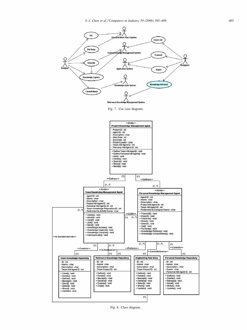
Fig. 7. Use case diagram.
Fig. 8. Class diagram.
Y.-J. Chen et al. / Computers in Industry 59 (2008) 395–409 403

Y.-J. Chen et al. / Computers in Industry 59 (2008) 395–409404
5.1.1.5. Describing use cases. Use case description attempts
to clarify the interactions between the actor and the system
through describing what, and how, the actor is doing by using
the system, instead of what the system is doing. The description
includes the purpose of the use case and the detailed flow of
events that follow the initiation of a use case. The following is a
description of the use case ‘‘Knowledge Retrieval’’.
5.1.2. Class modeling
Class modeling aims to identify the classes that are involved
in engineering knowledge management and their relationships.
Fig. 9. Sequence diag
Fig. 10. State diagra
It produces class diagrams that define the static, structural, and
data aspects of the system framework in terms of classes and
relationships that correspond to elements of engineering
knowledge management. This process helps promote under-
standing of real world engineering knowledge management and
thus provides a practical basis for system implementation.
A class diagram consists of classes, links and associations. A
class is a set of objects that share common attributes,
operations, semantic structure and behavior. An ‘‘object’’ is
a concept, abstraction, or thing in a certain application domain.
Meanwhile, a ‘‘link’’ is a physical or conceptual connection
ram (an example).
m (an example).

Y.-J. Chen et al. / Computers in Industry 59 (2008) 395–409 405
between instances of classes. Finally, an ‘‘association’’
describes a group of links that share a common structure
and semantics. Two of the most commonly used associations
are generalization and aggregation. Aggregation is the
‘‘part_of’’ relationship in which lower-level classes are
associated as a higher-level aggregate class. Meanwhile,
general-subclasses are a specialization of their super-class.
In the notation of UML, a class is indicated by a rectangular
box with three regions; class name, list of attributes, and list of
operations. An association is drawn as a line between classes,
with which a verb in a problem statement is associated.
Similarly, the UML notation for a link is a line between objects.
Meanwhile, an aggregation is drawn like an association, except
a small diamond that indicates the assembly end of the
relationships. Finally, the generalization is signified by a
triangle connecting a super-class to its sub-classes.
5.1.2.1. Discovering classes. Classes involved in engineering
knowledge management can be identified from various aspects.
These aspects include (i) the business process aspect from the
business process model, (ii) system organization aspect from
designed ‘‘system framework and configuration’’, and (iii)
system modeling aspect from use cases.
The business process aspect identifies elements involved in
the engineering knowledge management from the business
process model, and then maps them into classes in the system.
Classes discovered in this way are mostly those that process
actors can directly interact with, including information items,
process activities, and business level system functions (or
functional classes). They are referred to as ‘‘entity classes’’.
The use case analysis approach identifies objects by
examining the nouns and noun phrases from the use case
Fig. 11. System
description, which represent the key concepts significant to the
domain, and fulfil the definition of class and object. The nouns
and noun phrases may be objects, descriptions of the state of an
object, and external entities and/or actors. Classes identified in
this approach are mostly those that provide generic mechanisms
to support business level functionality.
5.1.2.2. Developing class diagram. Initially, use case descrip-
tions are analyzed for verbs, which reveals operations on
existing classes, and also new classes to provide the services
indicated by the verbs. Association, like operations, can also be
found by searching for verbs in source documents. While
operations reflect required functionality, associations reflect
required structural relationships between classes. At this stage,
the key object classes and their relationships, which are
identified from a process model, are drawn as an abstraction of a
class diagram.
The abstracted class diagram is then refined into a detailed
class diagram by specializing classes, refining class relation-
ships, and adding classes identified from use case analysis.
Fig. 8 illustrates the class diagram of a CPD-based distributed
engineering knowledge management system.
5.1.3. Dynamic modeling
Dynamic modeling addresses the dynamic behavior of
objects via the different events and associated state changes that
can happen to an object during different time periods. This
includes scenario analysis and state modeling.
5.1.3.1. Scenario analysis. A scenario is a sequence of
particular events that occur during the execution of a system.
Scenario analysis is performed by sequentially arranging the
architecture.

Y.-J. Chen et al. / Computers in Industry 59 (2008) 395–409406
events shown in use case descriptions. Scenario analysis results
in sequence diagram of object interactions arranged sequen-
tially. Fig. 9 depicts the sequence diagram of ‘‘Knowledge
Retrieval’’.
5.1.3.2. State modeling. The sequence diagram also indicates
events that trigger each object and events that are generated
from each object. Once identified, these events can be used to
define the state transition diagram of each object class. A state,
which is an abstraction of the attribute values and links of an
object, specifies the response of the object to input events. The
response to an event depends on the state of the object receiving
it and can include the object changing state, or sending another
event to the original sender or to a third object. A state diagram
that links states through events describes the behavior of a
single class of objects. Each event corresponds to a method of
the object. Fig. 10 represents the state diagram of class ‘‘a
engineering knowledge element/item’’.
Fig. 12. The user scenario for the functional feature and engineering specifica-
tion-based reference design retrieval.
5.2. System architecture design
The system architecture indicates the internal components
and packages, which make up the system, and their interactions.
Packages and components in the architecture are arranged in a
hierarchy of layers where each layer has a well-defined
interface.
The system architecture is developed by grouping classes
into components that have either a cooperative function or that
needed to be in close proximity for implementation efficiency.
Logically related components are then grouped into packages,
similar to components.
Generally, the top-level components of the packages in the
system architecture correspond directly to the modules defined
in the system framework, while the lower-level components are
added to implement the functions to support higher-level
components, but are not directly presented to users.
The architecture of the proposed system is designed based
on the concept of a three-tier distributed object technology. The
architecture is organized in three tiers of user presentation
business logic, and data management, as Fig. 11 shows. The
significance of the architecture is that the modularized software
components can be moved around at execution time and
deployed to optimize the technology and deliver the maximum
business benefit by separating user interface code, business
logic code and data storage code.
5.3. System implementation and scenario
Based on the results of system design and modeling, a CPD-
based engineering knowledge management system and the
involved core functions [9,10,21] were developed and
implemented in a virtual environment constituted by the
Enterprise System Engineering (ESE) Laboratory at National
Cheng-Kung University, Taiwan, and the Knowledge Manage-
ment System (KMS) Laboratory at Kaoshiung Medical
University, Taiwan. The former, which is equipped with Acer
ALTOS 9000 PC servers and Acer Power 590 h PC workstation
Fig. 13. Interface for identifying functional features and engineering specifica-
tions.

Fig. 14. Interface for ranking similarity of retrieved design cases.
Fig. 15. The engineering model of t
Fig. 16. The related engineering know
Y.-J. Chen et al. / Computers in Industry 59 (2008) 395–409 407
networked with five PC clients under Windows-NT environ-
ment, acts as a prime enterprise. The latter, which is equipped
with a SUN Space 20 workstation, a Silicon Graphics INDY
workstation, a Power Macintosh 6100/60, and an Acer ALTOS
9000 PC, plays the roles of guests, customers, remote
employees, and allied teams.
The applicability and feasibility of the model and the
framework have been examined by conducting a mold design at
Yong-Shiuh Mold Corporation, Taoyuan, Taiwan. According to
the investigation on the designers in the Mold Corporation, the
benefits of using the system include: (1) enhancing the
efficiency of collaborative design model by retrieving and
sharing distributed engineering design cases (engineering
knowledge), (2) increasing the trust among designers in
sharing distributed engineering knowledge, and (3) decreasing
the designer’s design time and cost in referring to the retrieved
similar design cases.
To describe the developed system with application in this
mold design, the functional feature and engineering specifica-
tion-based reference design retrieval is taken as an illustrative
example. Its user scenario is provided in Fig. 12 to address how
he most similar design case 07.
ledge of the engineering model.

Y.-J. Chen et al. / Computers in Industry 59 (2008) 395–409408
the retrieval is to be used. Fig. 13 shows the interface of
identifying the functional features and engineering specifica-
tions for the designers, while Fig. 14 shows the similar ranking
for the retrieved design cases. Moreover, Figs. 15 and 16
present the engineering knowledge contents of the most similar
design case. Meanwhile, Fig. 15 illustrates the engineering
model as a reference model for a working design, and Fig. 16
shows the relevant engineering knowledge of the engineering
model, including design intent and design experience of
establishing functional features and engineering specifications
on the engineering model.
6. Conclusions and further research
This work provides (i) a methodology for engineering
knowledge management in the context of collaborative product
design, (ii) a CPD-based engineering knowledge management
system characterized by reconfigureability and flexibility,
platform independence, and cooperativeness, and (iii) UML-
based enterprise system development procedure.
This work used the concepts of enterprise integration to
develop an engineering knowledge management methodology,
which includes a knowledge management-oriented engineer-
ing management work model, a distributed engineering
knowledge management framework, and rules and methods
for managing engineering knowledge. Rather than providing
point system functionality, this methodology offers a solution
for knowledge management in the context of collaborative
product design. The knowledge management-oriented engi-
neering management work model shows associativity between
collaborative product design and knowledge management. The
hierarchical and distributed management framework provides
a basic construct for developing system architecture compa-
tible with collaborative product design processes. The rules
and methods reveal the business logic for knowledge
management as well as the potential system functional
requirements.
Additionally, this work developed the CPD-based engi-
neering knowledge management system based on the
proposed methodology by applying principles for using
standardized modeling techniques, models and architectures
to make the system fully compatible and interoperable with
enterprise systems. The management system mainly consists
of modules of project management, knowledge management,
and knowledge service. Meanwhile, some core technologies
involved in the knowledge service such as ‘‘customer
requirement-based reference design retrieval’’, ‘‘functional
requirement-based reference design retrieval’’, ‘‘functional
feature-based reference design retrieval’’, ‘‘engineering
specification-based reference design retrieval’’, and ‘‘knowl-
edge compilation’’ were separately developed and imple-
mented in [9,10,20].
This study also demonstrated a systematic procedure for
developing an enterprise system that meets the needs of a large
business with complex business processes. It provides grounds
for a transition from domain processes, through solution
process to system models and architecture. This approach may
accelerate the development process of enterprise systems and
make systems more applicable.
Besides a structured methodology for developing and
implementing the engineering knowledge management systems
in collaborative design organizations, the system also provides:
(i) an effective method for recording both explicit and tacit
engineering knowledge, (ii) a convenient method for engineer-
ing knowledge reuse, and (iii) a valuable reference model and
framework that can be applied for other knowledge-intensive
works such as software system development, planning or
diagnosis.
Results of this study can increase product development
capability and quality, reduce development cycle time and cost,
and ultimately increase product marketability.
The major research direction for the future will be the
elicitation, integration and sharing of product knowledge with
human attitudes or cognition issues in collaboration environ-
ments. We will integrate knowledge management and human
factors/cognition techniques to develop relevant technologies,
such as knowledge elicitation technology and knowledge
building technology.
Acknowledgements
We would like to thank the anonymous reviewers for their
valuable comments, which have greatly improved the
presentation of this paper. This research was sponsored by
the National Science Council, Taiwan, ROC under Grant
numbers NSC93-2212-E-006-021 and NSC93-2917-I-006-
017.
References
[1] D.C. Anderson, T.C. Chang, Geometric reasoning in feature-based design
and process planning, Computer and Graphics 14 (2) (1990) 225–235.
[2] A. Basu, Perspectives on operations research in data and knowledge
management, European Journal of Operational Research 111 (1)
(1998) 1–14.
[3] G. Booch, J. Rumbaugh, I. Jacobson, The Unified Modeling Language
User Guide, Addition-Wesley, MA, 1999.
[4] D.W. Cockshoot, Engineering data management for concurrent engi-
neering globally, Computer & Control Engineering Journal 7 (2) (1996)
69–74.
[5] Y.M. Chen, M.W. Lian, Design and implementation of a collaborative
engineering information system for allied concurrent engineering, Inter-
national Journal of Computer Integrated Manufacturing 13 (1) (1999) 11–
30.
[6] Y.M. Chen, Y.D. Jan, Enabling allied concurrent engineering through
distributed engineering information management, Robotics and Compu-
ter-Integrated Manufacturing 16 (1) (2000) 9–27.
[7] Y.M. Chen, W.S. Shr, C.Y. Shen, Distributed engineering change manage-
ment for allied concurrent engineering, International Journal of Computer
Integrated Manufacturing 15 (2) (2002) 127–151.
[8] Y.M. Chen, C.L. Wei, Computer-aided feature-based design for net shape
manufacturing, Computer Integrated Manufacturing System 10 (2) (1997)
147–164.
[9] Y.J. Chen, Y.M. Chen, C.B. Wang, H.C. Chu, T.N. Tsai, Developing a
multi-layer reference design retrieval technology for knowledge manage-
ment in engineering design, Expert System with Applications 29 (4)
(2005) 839–866.

Y.-J. Chen et al. / Computers in Industry 59 (2008) 395–409 409
[10] Y.J. Chen, Y.M. Chen, H.C. Chu, C.B. Wang, D.C. Tsaih, Integrated
clustering approach to developing technology for functional feature and
engineering specification-based reference design retrieval, Concurrent
Engineering: Research and Applications 13 (4) (2005) 257–276.
[11] A. Ertas, J.C. Jones, The Engineering Design Process, Wiley, New York,
1993.
[12] C.T. Ho, Y.M. Chen, Y.J. Chen, C.B. Wang, Developing a distributed
knowledge model for knowledge management in collaborative develop-
ment and implementation of an enterprise system, Robotics and Compu-
ter-Integrated Manufacturing 20 (5) (2004) 439–456.
[13] G.R. Homer, D.M. Thompson, M. Deacon, A distributed document
management system, Computer & Control Engineering Journal 13 (6)
(2002) 315–318.
[14] Y.S. Ma, G. Chen, G. Thimm, S.H. Tang, Associations in a unified feature
modeling scheme, ASME Transactions Journal of Computing & Informa-
tion Science in Engineering 6 (2) (2006) 114–126.
[15] K.G. McIntosh, Engineering Data Management: A Guide to Successful
Implementation, McGraw-Hill, New York, 1995.
[16] D.E. O’Leary, Enterprise knowledge management, Computer 31 (3)
(1998) 54–61.
[17] G. Pahl, W. Beitz, Engineering Design: A Systematic Approach, Springer
Verlag, Berlin, 1984.
[18] C.P. Rupple, S.J. Harrington, Sharing knowledge through intranets: a
study of organization culture and intranet implementation, IEEE Transac-
tion on Professional Communication 44 (1) (2001) 37–52.
[19] W. Shen, D.H. Norrie, J.P. Barthes, Multi-Agent Systems for Concurrent
Intelligent Design and Manufacturing, Taylor & Francis, London, UK,
2000.
[20] G. Thimm, S.G. Lee, Y.S. Ma, Towards unified modeling of product life-
cycles, Computers in Industry 57 (4) (2006) 331–341.
[21] C.B. Wang, Y.J. Chen, Y.M. Chen, H.C. Chu, Knowledge refinement for
engineering knowledge management, Concurrent Engineering: Research
and Applications 13 (1) (2005) 43–56.
[22] C.P. Wei, J.H. Hu, H.H. Chen, Design and evaluation of a knowledge
management system, Software IEEE 19 (3) (2002) 56–59.
Dr. Yuh-Jen Chen is currently an assistant professor
of Department of Medical Information Manage-
ment, Kaohsiung Medical University, Taiwan,
ROC. He received his PhD and MS degrees in
Institute of Manufacturing Engineering of National
Cheng Kung University in 2005 and 2001 respec-
tively, and gained his BS degree from the Depart-
ment of Mathematics of Chung Yuan Christian
University, Taiwan, ROC, in 1999. His current
research interests include enterprise system devel-
opment and integration, knowledge engineering and management, and med-
ical informatics.
Dr. Yuh-Min Chen is currently a professor of Insti-
tute of Manufacturing Engineering, National Cheng
Kung University, Taiwan, ROC. He graduated from
The Ohio State University with a PhD degree in
Industrial and Systems Engineering in 1991 and
received his MS and BS degrees from National Tsing
Hua University, Taiwan, ROC, in 1981 and 1983,
respectively. Before joining the faculty of Institute of
Manufacturing Engineering in 1994, he worked as a
research engineer in Structural Dynamics Research
Corporation, USA for three years. His current research interests include
enterprise integration, engineering data and knowledge management, compu-
ter-aided concurrent engineering, and manufacturing information systems.
Dr. Hui-Chuan Chu is an associate professor of
Department of Special Education, National Univer-
sity of Tainan, Taiwan, ROC. She received her PhD
degree from Columbia University in 1998. Her
research interests are knowledge management, tea-
cher knowledge and integration of information tech-
nology in teacher education.