Embed Size (px)
Citation preview

4188-875 issue 5_07/10_Vigilon 4-6L EN54_Install
by Honeywell
Installation instructions
EN54 Vigilon 4/6 loop control panel basedFire detection and alarm system
Vigilon Fire System
GENT 2010
Designed to EN54 Pt 2 & 4
Healthy
15:45Fault
System Fault
Test
Fire
Power
Power Fault
CB254
Disablement
Sounder
1 2 3 4 5 6 7 8 9 10 11 12 13 14 15 16
17 18 19 20 21 22 23 24 25 26 27 28 29 30 30 32
Zones
PreviousNext
Delay
Verify
CB253

Contents
Notes on system installation - - - - - - - - - - 4Installation requirements - - - - - - - - - - - - - - - 4
Second fix installation - - - - - - - - - - - - - - - - 4
Fixture and fittings - - - - - - - - - - - - - - - - - 4
As fitted drawings - - - - - - - - - - - - - - - - - - 4
Cable type and routing - - - - - - - - - - - - - - - - 4
Fire sensor covers - - - - - - - - - - - - - - - - - - 4
Earth continuity - - - - - - - - - - - - - - - - - - - 4
Mains supply - - - - - - - - - - - - - - - - - - - - 4
Local Manual Call Point - - - - - - - - - - - - - - - 4
EN54 information - - - - - - - - - - - - - - - 5Optional functions with requirements of thisEuropean standard - - - - - - - - - - - - - - - - - - 5
System wiring- - - - - - - - - - - - - - - - - 5Requirements of cables - - - - - - - - - - - - - - - 6
Loop cable - - - - - - - - - - - - - - - - - - - - - 6
Mains Supply cable - - - - - - - - - - - - - - - - - 6
Typical Vigilon system - - - - - - - - - - - - - - - 7
Devices per Device loop - - - - - - - - - - - - - - - 8
Vigilon panels- - - - - - - - - - - - - - - - - 10Technical data- - - - - - - - - - - - - - - - - - - - 10
Installation checks - - - - - - - - - - - - - - - - - - 12
Back box installation - - - - - - - - - - - - - - - - 13
Semi-Flush fixing the control panel- - - - - - - - - - 14
Battery box for VIG1-72 panel - - - - - - - - - - - - 14
19 inch Rack mounting frames - - - - - - - - - - - - 15
Wiring the battery box - - - - - - - - - - - - - - - - 15
Cable termination and markings - - - - - - - - - - - 16
Mains and battery supply connections - - - - - - - - 16
Mains supply - - - - - - - - - - - - - - - - - - - - 16
Terminals for external circuits - - - - - - - - - - - - 17
Loop circuits - - - - - - - - - - - - - - - - - - - - 18
Master alarm circuits - - - - - - - - - - - - - - - - 19
Auxiliary relay circuits - - - - - - - - - - - - - - - 19
Clean contacts- - - - - - - - - - - - - - - - - - - - 19
RS232 / RS485 Communication - - - - - - - - - - - 20
Connecting a Remote printer - - - - - - - - - - - - - 20
On completion of wiring installation - - - - - - - - - 20
Mimic panel - - - - - - - - - - - - - - - - - 21Technical Data - - - - - - - - - - - - - - - - - - - 21
Typical Mimic illuminations - - - - - - - - - - - - - 21
Compatibility - - - - - - - - - - - - - - - - - - - - 22
Installation - - - - - - - - - - - - - - - - - - - - - 22
Mounting the backbox - - - - - - - - - - - - - - - - 22
External wiring - - - - - - - - - - - - - - - - - - - 23
How to fit the inner door assembly - - - - - - - - - - 23
Where to connect the internal cables - - - - - - - - - 24
How to fit the outer cover - - - - - - - - - - - - - - 24
Repeat Panel (loop connectable) - - - - - - - - 25Compatibility - - - - - - - - - - - - - - - - - - - - 25
Technical Data - - - - - - - - - - - - - - - - - - - 25
Installation - - - - - - - - - - - - - - - - - - - - - 26
Back box mounting - - - - - - - - - - - - - - - - - 26
Doors, Cables and Power up - - - - - - - - - - - - - 26
Repeat Indicator panel - - - - - - - - - - - - - 28Technical data- - - - - - - - - - - - - - - - - - - - 28
Cable - - - - - - - - - - - - - - - - - - - - - - - - 28
Installation - - - - - - - - - - - - - - - - - - - - - 28
S-Quad Sensors - - - - - - - - - - - - - - - - 29General specification - - - - - - - - - - - - - - - - 29
Base - - - - - - - - - - - - - - - - - - - - - - - - 29
Base Gasket- - - - - - - - - - - - - - - - - - - - - 29
Base labels - - - - - - - - - - - - - - - - - - - - - 29
Indicators - - - - - - - - - - - - - - - - - - - - - - 29
Dust Cover - - - - - - - - - - - - - - - - - - - - - 29
Do's and Don't - - - - - - - - - - - - - - - - - - - 29
Siting - - - - - - - - - - - - - - - - - - - - - - - - 30
Metal back box - - - - - - - - - - - - - - - - - - - 30
In - Out wiring to S-Quad bases - - - - - - - - - - - 30
Programmable input/output - - - - - - - - - - - - - 30
Tools for S-Quad - - - - - - - - - - - - - - - 31To remove an S-Quad - - - - - - - - - - - - - - - - 31
To fit an S-Quad - - - - - - - - - - - - - - - - - - 31
To fit a dust cover - - - - - - - - - - - - - - - - - - 31
To remove a dust cover - - - - - - - - - - - - - - - 31
S-Quad Semi-flush fixing kit (S4-FLUSH) - - - 32Technical data- - - - - - - - - - - - - - - - - - - - 32
Beam Sensor - - - - - - - - - - - - - - - - - 33Technical Data - - - - - - - - - - - - - - - - - - - 33
Do's and Dont's - - - - - - - - - - - - - - - - - - - 34
Test Keyswitch - - - - - - - - - - - - - - - - - - - 35
How to install an Angle bracket and fit a Beam sensor - 35
How to pre-assemble the parallel bracket - - - - - - - 36
How to install a Parallel Bracket and fit a Beam sensor 36
Duct kit - - - - - - - - - - - - - - - - - - - - 37Technical date- - - - - - - - - - - - - - - - - - - - 37
S3 Speech, Sounder Strobe mark II - - - - - - - 38Technical data- - - - - - - - - - - - - - - - - - - - 38
Installation - - - - - - - - - - - - - - - - - - - - - 39
Environmentally protected Heat Sensor- - - - - 40General data - - - - - - - - - - - - - - - - - - - - 40
Manual Call Points - - - - - - - - - - - - - - 41Technical data- - - - - - - - - - - - - - - - - - - - 41
Installation - - - - - - - - - - - - - - - - - - - - - 41
Keyswitch Interface / MCP - - - - - - - - - - 43Keyswitch assembly - - - - - - - - - - - - - - - - - 43
Technical data- - - - - - - - - - - - - - - - - - - - 43
Installation - - - - - - - - - - - - - - - - - - - - - 44
Operation - - - - - - - - - - - - - - - - - - - - - - 44
Label - - - - - - - - - - - - - - - - - - - - - - - - 44
Features- - - - - - - - - - - - - - - - - - - - - - - 45
Cables - - - - - - - - - - - - - - - - - - - - - - - 45
Installation - - - - - - - - - - - - - - - - - - - - - 45
Interface Modules for Vigilon -Low voltage (LV) Input/Output - - - - - - - - 45
Wiring diagrams - - - - - - - - - - - - - - - - - - 46
Technical data- - - - - - - - - - - - - - - - - - - - 47
2
Installation instructions

Interface Module for Vigilon -Medium Voltage (MV) Output - - - - - - - - - 48
Features- - - - - - - - - - - - - - - - - - - - - - - 48
Cables - - - - - - - - - - - - - - - - - - - - - - - 48
Installation - - - - - - - - - - - - - - - - - - - - - 48
Wiring - - - - - - - - - - - - - - - - - - - - - - - 48
Technical data- - - - - - - - - - - - - - - - - - - - 49
Mains Powered Interface (from Qtr 3 2010)- - - 50Technical Data - - - - - - - - - - - - - - - - - - - 50
Features- - - - - - - - - - - - - - - - - - - - - - - 51
Installation - - - - - - - - - - - - - - - - - - - - - 51
Mains supply - - - - - - - - - - - - - - - - - - - - 52
External wiring - - - - - - - - - - - - - - - - - - - 53
Options - - - - - - - - - - - - - - - - - - - - - - - 53
Vigilon Network Node - - - - - - - - - - - - 54Technical data- - - - - - - - - - - - - - - - - - - - 54
Power supply - - - - - - - - - - - - - - - - - - - - 55
Installation - - - - - - - - - - - - - - - - - - - - - 56
Semi-Flush fixing the Network node - - - - - - - - - 57
Terminate and mark cable - - - - - - - - - - - - - - 57
Mains supply - - - - - - - - - - - - - - - - - - - - 57
Mains and battery supply connections - - - - - - - - 57
Terminals for external circuits - - - - - - - - - - - - 57
Network connections - - - - - - - - - - - - - - - - 58
Master alarm circuits - - - - - - - - - - - - - - - - 58
Auxiliary relay circuits - - - - - - - - - - - - - - - 58
Clean contacts- - - - - - - - - - - - - - - - - - - - 59
Remote printer - - - - - - - - - - - - - - - - - - - 59
RS232 / RS485 Communication - - - - - - - - - - - 59
On completion of wiring installation - - - - - - - - - 59
Network of systems - - - - - - - - - - - - - - 60Copper network connections - - - - - - - - - - - - - 60
Fibre network connections - - - - - - - - - - - - - - 60
Network wiring - - - - - - - - - - - - - - - - - - - 61
Network cable screen continuity - - - - - - - - - - - 61
How to minimise cross talk - - - - - - - - - - - - - 61
Network cables - - - - - - - - - - - - - - - - 62
Domain Bridge across Networks - - - - - - - - 63
Vigilon system parts - - - - - - - - - - - - - - 67
3
Vigilon EN54 System
Preface
This is the fifth issue of the Installation instructions for the EN54 Vigilonsystem based on the 4/6 loop panels. These instructions must be read inconjunction with the recommendations in BS5839:Part 1 code of practicefor Fire detection and alarm system for buildings.
Associated DocumentsOperating instructions
Log book
Conventions
� This is a note to highlight important text that isnormally hidden in the main text.
� This is either a caution to prevent damage to theequipment or a warning to inform of dangerous conditionsthat may result in injury or death.
Abbreviations
ac - Alternating current
AS - Anti surge
C - Common
CH -Channel
dc - Direct current
DKC - Display keyboard card
EMC - Electromagnetic Compatibility
EOL - End of line
ESD - Electrostatic discharge
GND - Ground
I/F - Interface
IO or I/O - Input output
IOC - Input output card (Card15)
IP - Ingress protection
LCD - Liquid crystal display
LED - Light emitting diode
LPC - Loop processor card
LPCB - Loss prevention council certification board
LVD - Low voltage directive
MCC - Main controller card (CARD 0)
MCP - Manual call point
MICC - Mineral insulated copper cable
NC - Normally closed
N/O - Normally open
NVM - Non Volatile Memory (NVM on backplane CARD 14)
OC - Open circuit
OS - Outstation (Loop device)
PCB - Printed circuit board
PSU - Power supply unit
QB - Quick blow
Rx - Receiver
SC - Short circuit
S3 - Speech sounder strobe
S4 - Speech sounder strobe sensor
T - Anti-surge (fuse)
TBA - To be advised

Notes on systeminstallation
The power-up of the control panel andcommissioning of the system is done by the
Servicing organisation.
Installation requirements
It is recommended that the installer follow the general requirements ofBS5839:Part 1, which is the code of practice relating to fire detection andalarm systems for buildings. The installer must follow the relevant partsof BS7671 : 1992 Requirements for Electrical installations, IEE wiring
regulations 16th edition if installation is in the United Kingdom, UK.
Second fix installation
To prevent the possibility of damage or dirt degrading the performance orappearance of the products, the installed products must be suitablyprotected until all major building work in the area is complete.
� The installation of all outstanding parts is usuallycarried out during commissioning of the system.
Fixture and fittings
It is the installer's responsibility to provide adequate fixtures and fittingsfor the type of construction surface onto which a product is to beinstalled, whilst utilising the fixing points on the respective product. As anaid to this decision, the weight and overall size of each full assemblytogether with implications on cable entries and routing should be takeninto consideration.
� All these procedures assume that the cable, gland,steel box (BESA box) and other related accessories are providedby the installer.
As fitted drawings
The installer should acquire site specific information from the interestedparties, for details on the location of products for installation. Theacquired information together with this guide and the relevant standardsshould be used to assist the work.
Each product assembly can be identified from its package label. Thecontents of all packages should be checked for any discrepancies.
Cable type and routing
Appropriate attention must be given to ensure correct cable type isinstalled in accordance with as fitted drawings, site specific informationand recommendations of BS5839 Part 1 : 2002. The cables must beinstalled using cable manufacturers recommended fixings andaccessories.
Fire sensor covers
Each fire sensor may be supplied with a plastic dust cover and can beordered separately. If supplied, the cover must be fitted to prevent dustand dirt from the building work contaminating the fire sensor.
Earth continuity
All earth connection points should be clean to provide a goodelectrical conductivity path. To maintain the earth continuity allearth leads and fittings provided should be installed. The loop cablescreen must be continued through each system device on the loopcircuit, whether the earth is connected to the device or not.
�Do not rely on any part of building structure for earthing.
Some of the system products having metal enclosures have a zinccoating around the cable termination points, the coating provide a goodelectrical conductivity path for cable earth termination.
The zinc coating on the metal enclosures should not be damaged. Anydamage will expose bare metal, which can corrode and make a poorearth connection.
Mains supply
Mains supply to any fire alarm control and indicating equipment must bevia an unswitched 5A fused spur unit. A 'disconnect device' must beprovided to disconnect both poles and must have a minimum gap of3mm. The 'disconnect device' should be available as part of the buildinginstallation and must be easily accessible after installation is complete.
�All mains powered equipment must be earthed.
Local Manual Call Point
To comply with the requirements of EN54 : Part 2 : 1997 a conventionalmanual call point must be installed near the main control panel. The callpoint must be wired to an input line of an interface unit on the loop circuit.During commissioning call point input must be set up to evacuate allsectors without delay.
� Failure to install and configure a local manual callpoint in the manner described above when delays are set up onthe system will result in the panel not complying toEN54 : Part 2 : 1997.
4
Installation instructions

EN54 informationOptional functions with requirements of this European standard
The Control panel complies with the requirements of EN54 : Part 2 : 1997. In addition to the basic requirements of the standard the panel conformsto the following optional clauses:
Clause Description
7.8 Output to fire alarm devices
7.11 Delays to action outputs
8.3 Fault signals from point
9.5 Disablement of each addressable point
10 Test condition
System wiring
� If instructed by the project, the installer may need to terminate as well as connect the cables to the appropriate terminalblocks.
Cable separationWhere the outgoing and return cables of a loop which covers more than the equivalent of one zone they must not run together, for example, eitherclose to the Control Panel or in a service duct. There should be as much physical separation as possible between the cables and the mechanicalprotection of the cable should be to a particularly high standard. This is to minimise the risk of accidental damage to both cables. There should beseparation from the mains supply cable.
Lightning protectionWhere a loop cable or network cable is to be mounted to an external wall or between two buildings then consideration should be given to the use oflightning protection devices.
5
Vigilon EN54 system
VigilonControlPanel
1
1
2 2
Zone circuit
Sounder circuit
3230V ac
Other loop devices
VigilonControlPanel
1
1
2 2
Zone circuit
Sounder circuit
3230V ac 3
230V ac
Other loop devices
4
SecureNetwork
3
1
2
4
4
Loop voltagesurge protection
Mains 230Vacvoltage surgeprotection
Input Output linevoltage surgeprotection
Networkvoltage surgeprotection
There must be a good earthconnection to the voltage surgeprotection device.
Looppoweredinterface
Mainspoweredinterface
Vigilon Fire System
GENT 2010
Designed to EN54 Pt 2 & 4
Healthy
15:45Fault
System Fault
Test
Fire
Power
Power Fault
CB254
Disablement
Sounder
1 2 3 4 5 6 7 8 9 10 11 12 13 14 15 16
17 18 19 20 21 22 23 24 25 26 27 28 29 30 30 32
Zones
PreviousNext
Delay
Verify
CB253
Vigilon Fire System
GENT 2010
Designed to EN54 Pt 2 & 4
Healthy
15:45Fault
System Fault
Test
Fire
Power
Power Fault
CB254
Disablement
Sounder
1 2 3 4 5 6 7 8 9 10 11 12 13 14 15 16
17 18 19 20 21 22 23 24 25 26 27 28 29 30 30 32
Zones
PreviousNext
Delay
Verify
CB253

Requirements of cables
The British Standard BS5839 Part 1 : 2002 Code of practice for systemdesign, installation, commissioning and maintenance states therequirements for standard and fire-resisting cables in Clause 26.2 sectiond and e.
d) Standard fire-resisting cables should meet PH 30 classificationwhen tested in accordance with EN50200 and maintain circuit integrity ifexposed to the following test:
- a sample of the cable is simultaneously exposed to flame at atemperature of 830ºC - 0+40ºC and mechanical shock for 15min,followed by simultaneous exposure to water spray and mechanical shockfor a further 15min.
e) Enhanced fire-resisting cables should meet the PH120 classificationwhen tested in accordance with EN 50200 and maintain circuit integrity ifexposed to the following test:
- a single sample of the cable is simultaneously exposed to flame at atemperature of 930ºC - 0+40ºC and mechanical shock for a period of60min, followed by simultaneous exposure to water spray andmechanical shock for a further 60min."
� The cables listed in this manual are those that havebeen tested for EMC compliance with the system products.
Loop Cable usage
� There is a maximum limit of 1Km loop cable usageallowed per loop circuit. This maximum limit is the sum of thecable used to wire the main loop circuit, the spurs off main loopcircuit, plus cables that run to all input / output lines off the looppowered interface units installed on the same loop.
There is a further maximum limit of 100m cable run allowed perinput / output line off loop powered interface unit.
Loop cable
Vigilon loop cable carries both data and power supply, therefore itsselection is important. Note the following:
� In countries where the European EMC directive is inforce, only EMC Compliant cables are to be used.
� The loop cable usage must not exceed 1Km. Thisincludes the cable usage on main loop, spur circuitsand interface lines.
� Single pair cable must be used. It is NOT permissible torun mixed loops or outgoing and return pairs in a multicore cable, due to inadequate separation and possibleelectrical interference problems.
� Each core of the loop cable must be 1.5mm2 crosssection area.
� the cable screens must be capable of being earthed ateach system device (outstation).
� Red is the preferred cover sheath for fire applications.
� The specified loop circuit cables are also suitable forwiring master alarm, auxiliary relay, input/output linesand mains supply.
Enhanced cables
� Mineral insulated cable (MICC) to BS6207:Part 1
� Approved Enhanced cable:Draka Firetuf Plus Enhanced FTPLUS2EH1.5RD
� Prysmian (formally Pirelli) FP PLUS *
Standard cables
Approved EMC cables for loop wiring
� Draka Firetuf EMC Standard 1.5mm2
FTEMC2EH1.5RDR
� Draka Firetuf FTZ2E1.5 FIRETUF OHLS *fire resistant data cable
� Raydex CDT FG950 *
� Cavicel SpA FIRECEL SR 114H *distributed by Cables Britain
� AEI Cables FIRETEC *
� BICC Pyrotenax FLAMESIL FRC *
� Datwyler LIFELINE *
� Alcatel cable PYROLON E * distributed by Winstonlead
� Huber & Suhner RADOX FR *
� Prysmian (formally Pirelli) FP200 FLEX *
� Prysmian (formally Pirelli) FP200 GOLD *
� The cables marked * utilise laminated aluminium tapewith a tinned drain wire for electrostatic screening. Under certainenvironmental conditions galvanic action may take placebetween the aluminium and the drain wire. This will severelydegrade EMC performance as the foil to drain wire impedancewill increase.Armoured variants of the cables marked * can also be used onloop circuit.
Mains Supply cable
The mains supply cable must be a standard fire-resisting type and shouldmeet PH30 classification, like the standard and enhanced cables listedabove.
6
Installation instructions

Typical Vigilon system
The loops allow wiring of addressable devices like fire sensors, alarm sounders, call points, interface units, mimic and repeat panels. Acombined maximum of up to 200 devices is allowed per loop circuit, a further limit on a loop circuit is determined by the load factor.
7
Vigilon EN54 system
Repeat Panel
Conventional 2-wiresystem equipment(eg 7800 detectors)
Conventional 2-wiresystem equipment
230V ac / 24V dc
Magnetic doorrelease
230V ac
230V acOutput to control plant
Input output signalsmay be used to controland monitor:Plant equipmentBuilding management system
Tx Rx
Loop circuit 1
T S3
S3
Mimic Panel
Spur
T
S3
S4
S4
230V ac
Addressable System Devices
- Manual Call Point
- T BreakerT
- End of Line Unit
- Magnetic door release
Conventional Products offinterface inputs
- Alarm sounder
- Conventional Fire Detector
- Manual Call Point
- Beam sensorTransmitter and receiver
Tx
Rx
S3
- S-CubedVoice enhanced Speech,Sounder, Strobe Unit
S4 - S-Quad
Sensor Speech Sounder & Strobe
- S4 1-Inputloop powered interface
S4i
- S4 1-Output + Confirmationinput loop powered interface
S4o
- S4 Mains switching outputloop powered interface
S4o~
- S4 4-Input/Outputloop powered interface
S4i/o
- Remote LEDL
LED off S sensor4
S4
S4
S4
S4i/o
S4i
S4o~
S4
Optional Loop circuits 2 to 4/6
Fire /FaultTwo auxiliary relayscontacts rated 1A @ 24Vdc
Battery box(needed for
VIG1-72 only)
ConventionalSounders on(Two master
alarm circuits)250mA per circuit
Cleancontacts rated1A @ 24Vdc
230V ac
EN VigilonControl Panel
Port 1 (RS485)
Port 0 (RS232)
Vigilon Fire System
GENT 2010
Designed to EN54 Pt 2 & 4
Healthy
15:45Fault
System Fault
Test
Fire
Power
Power Fault
CB254
Disablement
Sounder
1 2 3 4 5 6 7 8 9 10 11 12 13 14 15 16
17 18 19 20 21 22 23 24 25 26 27 28 29 30 30 32
Zones
PreviousNext
Delay
Verify
CB253
S4MP
- S4 - Input/Outputmains powered interface unit
S4MP
S4
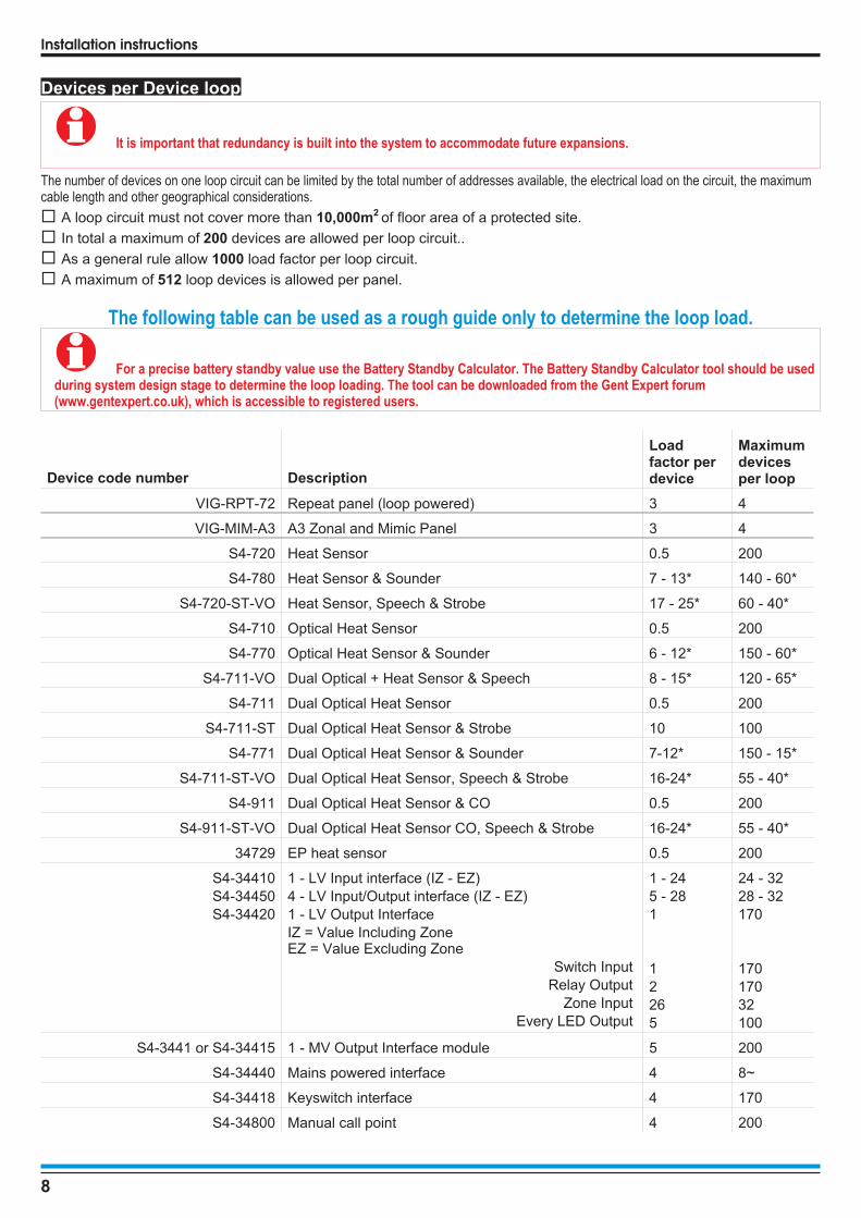
Devices per Device loop
� It is important that redundancy is built into the system to accommodate future expansions.
The number of devices on one loop circuit can be limited by the total number of addresses available, the electrical load on the circuit, the maximumcable length and other geographical considerations.
� A loop circuit must not cover more than 10,000m2 of floor area of a protected site.
� In total a maximum of 200 devices are allowed per loop circuit..
� As a general rule allow 1000 load factor per loop circuit.
� A maximum of 512 loop devices is allowed per panel.
The following table can be used as a rough guide only to determine the loop load.
� For a precise battery standby value use the Battery Standby Calculator. The Battery Standby Calculator tool should be usedduring system design stage to determine the loop loading. The tool can be downloaded from the Gent Expert forum(www.gentexpert.co.uk), which is accessible to registered users.
Device code number Description
Loadfactor perdevice
Maximumdevicesper loop
VIG-RPT-72 Repeat panel (loop powered) 3 4
VIG-MIM-A3 A3 Zonal and Mimic Panel 3 4
S4-720 Heat Sensor 0.5 200
S4-780 Heat Sensor & Sounder 7 - 13* 140 - 60*
S4-720-ST-VO Heat Sensor, Speech & Strobe 17 - 25* 60 - 40*
S4-710 Optical Heat Sensor 0.5 200
S4-770 Optical Heat Sensor & Sounder 6 - 12* 150 - 60*
S4-711-VO Dual Optical + Heat Sensor & Speech 8 - 15* 120 - 65*
S4-711 Dual Optical Heat Sensor 0.5 200
S4-711-ST Dual Optical Heat Sensor & Strobe 10 100
S4-771 Dual Optical Heat Sensor & Sounder 7-12* 150 - 15*
S4-711-ST-VO Dual Optical Heat Sensor, Speech & Strobe 16-24* 55 - 40*
S4-911 Dual Optical Heat Sensor & CO 0.5 200
S4-911-ST-VO Dual Optical Heat Sensor CO, Speech & Strobe 16-24* 55 - 40*
34729 EP heat sensor 0.5 200
S4-34410
S4-34450
S4-34420
1 - LV Input interface (IZ - EZ)
4 - LV Input/Output interface (IZ - EZ)
1 - LV Output Interface
IZ = Value Including ZoneEZ = Value Excluding Zone
Switch Input
Relay Output
Zone Input
Every LED Output
1 - 24
5 - 28
1
1
2
26
5
24 - 32
28 - 32
170
170
170
32
100
S4-3441 or S4-34415 1 - MV Output Interface module 5 200
S4-34440 Mains powered interface 4 8~
S4-34418 Keyswitch interface 4 170
S4-34800 Manual call point 4 200
8
Installation instructions

Device code number Description
Loadfactor perdevice
Maximumdevicesper loop
S4-34760 Venturi-Air Duct Kit 0.5 200
S4-34740 Beam sensor pair 3 -per pair 16 (ie 8pair)
34701 Tee breaker 0.4 127
S2IP-ST-XRS2IP-ST-XW
Strobe RedStrobe White
9
22
10040
S3-SN-XS3IP-SN-X
S2IP-SN-X/XX
Sounder (standard tone) 5 200
S3-VP-XS3IP-VP-X
Sounder (standard tone) - with speech 5 - 17 200 - 55
S3-VP-ST-XRS3IP-VP-ST-XR
Sounder (standard tone) with red strobe- Speech complex tone with red strobe
13 - 25 80 - 40
S3-VP-ST-XWS3IP-VP-ST-XW
Sounder/speech with white strobe 37 25
S3IP-SN-ST-XR Sounder standard tone with red strobe 13 80
Supported products
34415 or34410
Single Channel Interface orLoop powered zone module
10 100 ~
34450 Loop powered interface 4 30~
The load factors and maximum devices stated in the table above are revised due to changes in product specification
~ - A maximum of up to 100 input channels are allowed per loop.
* - These values are applicable when sounder is operating in turbo mode or with bell tone.LV - Low voltageMV - Medium voltage
9
Vigilon EN54 system

Vigilon panelsThe Vigilon panels (VIG1-24 or VIG1-72) are analogue addressable firealarm panel designed to the requirements of EN54 Parts 2 and 4. Thepanels can accommodate up to 4 or 6 loop circuits for the connection ofVigilon range of analogue and addressable devices. The panels haveintegral mains derived power supply. The VIG1-24 panel has integralbatteries and the VIG1-72 panel have batteries fitted in a separateenclosure for extended standby supply. The batteries supply standbypower in the event of mains power failure. A lockable front door preventsunauthorised access to fire alarm controls but allows all of the indicatorsto be seen. The panels have integral zonal indicators to provide zone fireor fault indications. Two push button controls are located on the frontdoor below the display that enable Fire messages to be scrolled in theevent of multiple fires. The panels are designed for surface or semi-flushmounting with rear and top cable entry points.
Features
� Analogue addressable fire alarm control panel
� Supports up to four or six loop circuits per panel
� Up to 200 addressable devices can be connected to aloop circuit. Devices like sensors, MCPs and interfaceunits etc.
� Two master alarm circuits
� Optional RS485 to connect to a Repeat Indicator panel
� Optional RS232 to connect to another control panel(domain bridge) or external printer
� USB for commissioning tool connection
� Two sets of auxiliary relay change over contactsconfigurable to operate with fire, fault or disablement
� One set of clean voltage-free change over contacts thatoperates with fire events
� Standby supply to power the system during mains failure
� LCD alphanumeric display with back light to show eventinformation
� Integral 32 zone LED indicators (with First fire steady /flashing or disable integral zone indication's options)
� LED lights for event indication
� Local buzzer gives audible sound to announce events
� Push button for essential controls and menu options
� Four programmable control buttons (U1 to U4)
� A remote battery box (for VIG1-72 panel only)
Technical data
Control panel
Standard Designed to EN54 Part 2:1997 +AMD 1:2006 (and include optionalclauses 7.8, 7.10, 7.11, 8.3, 9.5and 10)
Approval LPCB approved
Panel dimensions inmm with outer door
height 543 x width 406 x depth 172
Panel weight
VIG1-24 10.2Kg approximately + 2 batteries12V 21Ah battery - weight 6Kgeach
VIG1-72Battery box#
# with 4 batteries# with 8 batteries
10.2Kg7.2Kg31.2Kg55.2Kg
Storage temperature -10 to 55ºC
Operatingtemperature
-5 to 40ºC
Relative Humidity(Non condensing)Temperature-5 to 40°C
up to 90%
Emission BS EN61000-6-3:2001 Part 1Residential, Commercial & LightIndustry Class B limits.
Immunity BS EN50130-4: 1996: Part 4Alarm systems: Electromagneticcompatibility. Product familystandard: Immunity requirementsfor components of fire, intruder andsocial alarm systems.
Ingress Protection IP30
Colour Door: Grey (Pantone 422)Back box: Graphite Grey(RAL 7024)
Loops The panel is supplied with a loopcard for 1 loop circuit. It cansupport up to 4/6 Loop circuits,using optional loop cards.
Network Two types of network cards areavailable for secure networkconnection:Fibre Optics - 2Km maximum
Copper (RS485) - 1.2Km maximum
RS232 and RS485connections
The panel will require an optionalstandard IO Card to facilitateRS232 for connections for domainbridging and remote printer. Themaximum cable length allowed forRS232 is 15m.
The panel has an RS485 port toaccept the Repeat Indicator panels.
The Commissioning tool can beconnected to the panel via theUSB port on the Master ControlCard.
10
Installation instructions
Vigilon Fire System
GENT 2010
Designed to EN54 Pt 2 & 4
Healthy
15:45Fault
System Fault
Test
Fire
Power
Power Fault
CB254
Disablement
Sounder
1 2 3 4 5 6 7 8 9 10 11 12 13 14 15 16
17 18 19 20 21 22 23 24 25 26 27 28 29 30 30 32
Zones
PreviousNext
Delay
Verify
CB253
042bc

Devices per loop A maximum of 200 addressabledevices per loop circuit.
Device label Each device can be given a32 character label for identification.Each MCP is restricted to28 character label.
Plug in Card slots
MCC / LCC -P1IOC / N/W -P2
Loop 1 - P3Loop 2 - P4Loop 3 - P5Loop 4 - P6
Loop 5#, IOC orN/W-P7
Loop 6#, IOC orN/W -P8
Master Control card - suppliedInput Output card / Network cardLoop card - suppliedLoop card optionLoop card optionLoop card optionLoop card#, Input Output card orNetwork cardLoop card#, Input Output card orNetwork card
# - for VIG1-72 only
Clean contacts 1 set of voltage free change overcontacts rated 1A @ 24Vdc, activewith a fire event.
Master alarm circuits 2 - (24 volts nominal)400 mA max per circuitMA1 - fuse 1A FS1MA2 - fuse 1A FS2
(20 x 5mm) on Terminal card.
Auxiliary relays
Aux relay 1
Aux relay 2
Voltage-free contacts rated1A @ 24Vdc2 sets of change over contactsconfigured to operate immediatelywith Fire event. The relay isnormally de-energised.
2 sets of change over contactsconfigured to operate immediatelywith Fault event. The relay isnormally energised.
The relays can be re-configured tooperate with Fire, Fault orDisablement event, with amaximum delay of up to10 minutes and can operate in anormally energised or de-energisedstate.
Internal sounder To announce Fire and Faultevents, plus give a key pressconfirmation beep.
Display Alpha-numeric display - 8 lines by40 characters per line, back-lit,(Black characters on greenbackground, liquid crystal display)
Menus [Control], [Setup], [Information] and[Test Engineering] menusaccessed via Menu On/Off, F1, F2,F3 and F4 buttons.
Controls(with door closed)Access level 1
Next and Previous buttonsoperable during Fire condition only.
Controls(with door open)
Access level 2a
User having door key
Sound Alarms, Silence Alarms,Reset, Cancel Buzzer, Verify,F1-F4 keys, Menu On/Off key,QWERTY key board, U1-U4 keysavailable if configured to performsite specific actions by triggering ofcommand builds 251, 252, 253 and254.
Access level 2b
User having an outerdoor key andcustomer password
Access as level 2a plus access tocomplete level 2 menu commands.
Access level 3
Engineer having anouter door key andengineer password
Access as level 2b plus access toall level-3 menu commands.
Indicators Fire (red)
32 - Zones (red) hidden until litPower (green)Power Fault (amber)Delay (amber)Test (amber)Verify (amber)CB253 CB254 (amber)Fault (amber)Disablement (amber)System fault (amber)Sounder (amber)
Logs Active Logs: Fire, Fault andDisablement
Historic log: All events
Event logs: Fault, Disablement,Warning, Supervisory, Exceptionsand Historic fires.
Printer The integral printer if fittedoperates when the outer door isopen. The 'printer menu' include:ON, OFF, Line feed and Test printcontrols.
An optional remote printer can beconnected to the panel.
Batteries and Battery BoxThe batteries provide 24/72 hour standby supply plus power to alarmload for 30 minutes. The Battery Loop Loading calculator can be used todetermine the load on the loop to achieve the standby power in the eventof mains failure. The battery box is only used with the VIG1-72 panel andcan be installed in a remote location up to 10m cable distance away fromthe control panel when using 1.5mm2 MICC. When using 2.5mm2 MICCthen the cable then this distance can be increased to 15m.
Battery boxdimensions in mm
height 437 x width 421 x depth 174
Terminals Accept cable size of up to 2.5mm2
Battery box weight(includingbatteries)
31.2Kg with 4 batteries
55.2Kg with 8 batteries1 x 12V 21Ah battery weight is 6Kg
11
Vigilon EN54 System

Battery VIG1-24
VIG1-72
Batteries installed in the panel2 x Powersonic 12V 21Ahr -(supplied)Model number PG12V21 B
Batteries installed in a battery box4 x Powersonic 12V 21Ahr -(supplied).Model number PG12V21 BThe battery box can optionallyaccommodate up to 8 x Powersonic12V 21Ah
Temperaturemonitoring
Inside the VIG1-24 panel and in thebattery box for VIG1-72 panel - forautomatic adjustment of batterycharge voltage with change intemperature.
� Always use the recommended replacementbattery, as there is a risk of an explosion if incorrectbattery is used.
Power supply
Standard Designed to EN54 Part 4:1997 +AMD 1:2002 and AMD 2:2006
Mains operatingvoltage
230V 50Hz +10% -6% isprotected by a 3.15A (T) 250VCeramic (20 x 5mm) on PSU.Input current - 1.4A
Nominal supply voltagefor master alarmcircuits
24V +1V, -4V
Battery circuit(s) Terminals to connect to internallyor externally housed batteries.Batteries reach fully chargedstate in 72Hr for VIG1-24 andVIG1-72.
Battery current withmains disconnected
VIG1-24 - 4.5A max.VIG1-72 - 6.2A max.
Light indications To show the status of PSU
PSU Fuses Mains
44V supply
Battery charge circuit 1
Battery charge circuit 2
FS6 T3.15A Ceramic
FS2 F3.15A Glass
FS1 F10A Ceramic for VIG1-72onlyFS7 F5A Ceramic for VIG1-24 only
FS3 F10A Ceramic for VIG1-72 only
All fuses 20mm x 5mm size
Storage temperature -10 to +55ºC
Operating temperature -5 to 40ºC
Relative Humidity(Non condensing)
up to 90%Temperature -5 to 40°C
Maximum current frombattery without mainsconnected
5.8A
EN54 Part 4 dataVIG1-24
VIG1-72
I min -> 780uA
I max a -> 108mA @ 43.5V
I max b -> 1.6A @ 43.5V and2 x 0.5V @ 24V
Ri max -> 1.25RUVLO -> 20.7V ± 0.4V
I min -> 780uA
I max a -> 162mA @ 43.5V
I max b -> 2.4A @ 43.5V and2 x 0.5V @ 24V
Ri max -> 1.25RUVLO -> 20.7V ± 0.4V
� Hazardous voltages may still be present even ifthis indication is extinguished.
Installation checks
A VIG1-24 and VIG1-72 panels include the following parts:
� Back box assembly with PSU to power the Control panel
� Inner door for Control panel
� Moulded outer door
� Loop Card (1- loop card supplied), can accommodateup to 4 maximum in VIG1-24 and up to 6 in VIG-72panel
� Main Controller Card for VIG-24 or VIG-72 panel
� VIG1-24 is supplied with 2x12V 21Ah batteriesVIG1-72 is supplied with 4x12V 21AH batteries forinstallation inside a battery box (the battery box can holdup to 8 x 12V 21Ah batteries)
� A Battery box is supplied with VIG1-72 panel only
Parts supplied in spares packs
PartQty
VIG1-24
QtyVIG1-72
Batterybox
Cable tie 3 3
Ferrite core
1 1
22K 0.5W Resistor
2 2
Battery lead
1
Spade tag 2
Link lead
1 4
Battery lead fused
4
Instructions1 1 1
12
Installation instructions
i

20 x 5mm
Fuse 5A QB Ceramic
1
20 x 5mm
Fuse 3.15A AS Ceramic
1 1
20x 5mm
Fuse 3.15A QB glass
1 1
20x 5mm
Fuse 10A QB Ceramic
2 4
Terminal block1
Adhesive backed foampad
1 1
Each battery pair of 2 x 12V 21Ah is supplied with:
Back box installation
These instructions cover installation of the panel and battery box. Thecards and batteries are installed during the commissioning of the systemby the servicing organisation.
� The control panel can be surface or flush mounted.The only time it should not be flush mounted is when the batterybox is close fitted beneath the control panel.
a. Identify the package VIG1-24 / VIg1-72 and check thatit contains all the parts.
b. Remove the temporary cover from the Back box.
c. Knock out/in the required cable entry points from theControl panel back box and from the Battery box.
d. Use the fixing points provided to mount the Back boxand Battery box to the wall using suitable fixings.
� The fixings must support a fully assembledControl panel and Battery box.The VIG1-24 panel with batteries weigh 22.2Kg and theVIG1-72 panel weigh 10.2Kg. The batteries for a VIG1-72panel are mounted in an external battery box weighingeither 31.2Kg (4 batteries) or 55.2Kg (8 batteries).
e. Stick the adhesive backed foam pad supplied to covergaps around the centre key-hole fixing point in the backbox. This is done to seal any gaps to prevent ingress.
f. Terminate each cable at the entry point leaving 400mmtail wire length and mark each core to identify its finalconnecting point.
� If the mains cable is not connected to therespective terminals then ensure the tail ends are insulatedto guard against accidental switching ON of the mainssupply.
13
Vigilon EN54 System
50
2m
m
390mm
Cable entry points
18 - Back
18 - Top
2 - Bottom side
(on the right)Mains supply
cable
Knock outs
9-off Earth points
(1-0ff bottom side
on the right hand)
Back box
for VIG-72 shown
5-off Backbox
fixing points
(includes
1 keyhole)
1.7
m
Floor level
Dust
cover
over
backplane
Earth to
Inner door
Backplane
0V
to printer
PSU
Fitted on VIG1-72 only
Adhesive backed foam pad
to seal up gap to prevent
ingress
4 x bolts 4 x spring washers4 x washers

Semi-Flush fixing the control panel
The control panel may be semi-flush mounted using a semi-flush surround VIG-24-FLUSH. A stainless steel variant of thesemi-flush surround (VIG-FLUSH-SS) will require a stainless steel door VIG_DOOR_SS.
a. Check the contents of the semi-flush surround package.
b. Cut out an aperture in the wall to allow the semi-flush surround to be fitted, see the diagram below for dimensions ofthe aperture in the wall.
c. Using the fixing holes on the semi-flush surround secure it into the aperture side walls.
d. Knock out the appropriate top or rear cable points on the control panel back box.
e. Route the cables through the cable entry points into the back box and at the same time insert the back box into thesemi-flush surround.
f. Fit the back box to the semi-flush surround using the 5 - 5mm fixing-screws supplied in the spares pack.
Battery box for VIG1-72 panel
The connecting battery cables from the control panel to the battery box can be either 1.5mm2 or 2.5mm2.
The battery box can be mounted beneath the control panel or in a remote location. The battery box can be up to 10m cable distance away using1.5mm2 cable or 15m cable distance using 2.5mm2 cable.
14
Installation instructions
Control Panel
Cross section of
the wall to which
the panel is to be
semi-flush mounted
Flush
Surround
5mm diameter
fixing holes
Aperture Height:
- Control panel510mm
Aperture Width:
- Control panel390mm
Aperture depth
- 132mmControl panel
semi-flush surround
5-off Backboxfixing points
Terminalcard
Cable entry points3 - Back5 - Top
Earth lead
Locakable Door Backbox
Earth points2-off on the top sideof the case
Hole for battery cablesfrom terminal cardto batteries on lower shelf
Upper Shelf
Lower Shelf

19 inch Rack mounting frames
Wiring the battery box
15
Vigilon EN54 system
10 off holes for securingto 19" Rack
4 holes withthreadedbushes forsecuringcontrol panel
14U
6 off holes for securingto 19" Rack
4 holes withthreadedbushes forsecuringbattery box
9U
Panel
Battery box
Battery Box
Here the battery box isshown mounted beneaththe control panel
Panel
Control
panel
Battery
box
Control panelBattery box
in a remote
location
Cable distance
1.5mm sq - 10m maximum
2.5mm sq - 15m maximum
TH-TH+
B2-B2+
B1-B1+
P4 P3
P2P1
P6
TH1
P2
P3
P1
TH+TH-B2+
B2-B1+
B1-
Wiring optionsWhere the wiring is terminated
at the top of the panel ensure
the cables run neatly
down the side of the
enclosure to the terminals

� To maintain earth continuity, an earth lead (notsupplied), is required to be fitted to an earth point in the controlpanel with the other end to an earth point in the battery box.
� Unused knockouts that have been removed must NOT
be left open.
Cable termination and markings
The wires between the termination point and terminals should be asshort and straight as possible.
Where a cable has an earth drain wire, the wire must be fitted to theearth point nearest to the cable entry point. Ensure the drain wire lengthdoes not exceeding 50mm.
Terminate each cable at the dedicated entry point on the enclosure,using the cable manufacturer recommended techniques.
Where the cable is not required to be connected, leave 400mm tail wirelength (unless otherwise instructed) and mark each core identifying itsfinal point of connection.
Where the cable is required to be connected, ensure it is secured to therespective terminal.
Wiring tests
� Don't undertake high voltage insulation testsWITH THE CABLES CONNECTED to the panel and systemdevice terminals. Such a test may damage the electronicscircuitry in loop devices and at the panel.
Mains and battery supply connections
The mains and battery supply cables must be installed to the stage tofacilitate the power up for commissioning, which is carried out by theServicing organisation.
� Where mains cable is to remain disconnected, itstail ends must be insulated to prevent dangerousconditions arising in the event of accidental switching Onof the mains supply.
Mains supply
� Ensure that the mains supply cable enters thepanel through a dedicated cable entry point.
� These fire alarm system products are NOT designedto be powered from IT Power systems.
All mains powered equipment must be earthed.
Mains supply to any fire alarm control and indicating equipment must bevia an unswitched 5A fused spur unit. A disconnect device must beprovided to disconnect both poles and must have a minimum gap of3mm. The Disconnect device should be available as part of the buildinginstallation and must be easily accessible after installation is complete.
The fused spur isolator cover should be marked:FIRE ALARM - DO NOT SWITCH OFF
The fire alarm equipment’s fused spur unit must be fed from adedicated switch or protective device at the local mains supplydistribution board.
16
Installation instructions
MICC CABLE
GLAND
BRASS
LOCKNUT
ZINC PLATED
LOCK WASHER GLAND
BOARD
TERMINALS
MICCCABLE TERMINATION
MICC CABLE
GLAND
BRASS
LOCKNUT
ZINC PLATED
LOCK WASHER
Softskin Cable
GLAND
BOARD
TERMINALS
EARTHDRAINWIREShould notbe more than50mm longand must besleeved
CABLE TERMINATION
PANEL
enclosure
Softskin (Fire Tuf)
Dedicated mains supplyfrom consumer unit
5A Unswitchedfused spur unit
P2L N
mains cable
27
0m
m
50
mm
5mm
mainscable
The mains cable must be strippedback to the length shown to allowlive and neutral wires to be woundtwice through the ferrite core.
ferritecore
(supplied)3
5m
m
Panel
45
mm
must be sleeved
Use cable ties(supplied)
Gland
PSU PCB

Terminals for external circuits
The Terminal card holds all the terminals for the connection of external circuits. The exceptions are:
� terminals for CARDS in slots P7 and P8, these are located on the Backplane
� terminals for mains supply, these are located on the mains terminal block
� terminals for batteries, these are also optionally located on the PSU.
17
Vigilon EN54 system
CARD 4LOOP 4
L1 0V L2 0V
CARD 3LOOP 3
L1 0V L2 0V
CARD 2LOOP 2
L1 0V L2 0V
CARD 1LOOP 1
L1 0V L2 0V
RS485A 5V B 0V
RS232Tx CTS Rx RTS (WITH IO CARD IN SLOT P2 OF BACKPLANE)
P4
MA1+ MA1- MA2+ MA2-
Master alarm
P5
Clean CNC C NO
P6
Auxiliary Relay 1NC C NO NC C NO
P7
Auxiliary Relay 2NC C NO NC C NO
P8
RS232 0V0V 0V 0V 0V
P12
PB1
PB2
BackplaneTerminal card
Quick release terminals
P2 P3
0V1 +VE1 -VE1 0V2 N/C N/C +VE2 -VE2 (WITH NETWORK CARD IN SLOT P2 OF BACKPLANE)
NETWORK CARD IN SLOT P80V1 +VE1 -VE1 0V2 N/C +VE2 -VE2 N/C
LOOP CARD IN SLOT P8 (Loop 6)L1 0V L2 0V
IO CARD IN SLOT P8A 5V B 0V CTS Rx RTS TX
IO (RS232) CARD IN SLOT P7N/C 0V CTS RX RTS TX
LOOP CARD IN SLOT P7 (Loop 5)L1 0V L2 0V
P2L N
PSU board (located behind the cardboard cover)

Loop circuits
The loop circuits can each accept connection of addressable devices amaximum of 200 devices is allowed per loop. To maintain earthcontinuity on a loop it is important for the loop cable screen to becontinued through each system device, whether the earth is connected toa device or not.
� As every loop device has an isolator fitted, it is notnecessary to apply special attention where there are more than32 devices. However no more than a maximum of 512 devicesshall be installed on one control panel.
�A loop circuit must not cover more than 10,000m2 of floor area ofa protected site.
A spur circuit must always be taken from the line commonterminals of a 3-way loop device.
A spur should not cover more than the equivalent of one zone asdefined in BS5839 : Part 1.
18
Installation instructions
L2
02
S device(2-way)
3
01
L1
L1
01
L2
02
02
L2
01
L1
++
+
+L1
L2
0 V
L1
0V
Manual call point
L2
0V
PANEL
S-Quad
2 - way device
S device(2-way)
3
Earth tometal box
Terminal Card
LOOP CIRCUIT 1
Note: The 0V terminalsin the terminal plateare electricallyconnected together.
L1 0V L2 0V
LOOP n
IN4OUT5
C3
S-Quad
IN4OUT5
C3
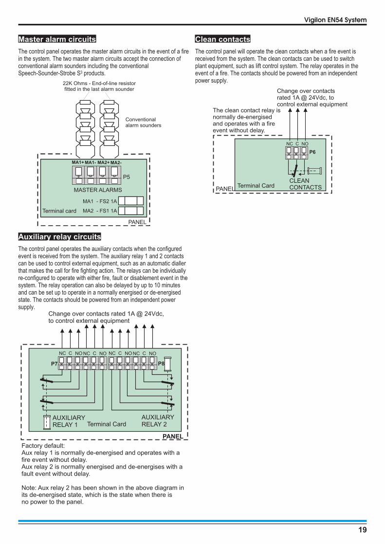
Master alarm circuits
The control panel operates the master alarm circuits in the event of a firein the system. The two master alarm circuits accept the connection ofconventional alarm sounders including the conventionalSpeech-Sounder-Strobe S3 products.
Auxiliary relay circuits
The control panel operates the auxiliary contacts when the configuredevent is received from the system. The auxiliary relay 1 and 2 contactscan be used to control external equipment, such as an automatic diallerthat makes the call for fire fighting action. The relays can be individuallyre-configured to operate with either fire, fault or disablement event in thesystem. The relay operation can also be delayed by up to 10 minutesand can be set up to operate in a normally energised or de-energisedstate. The contacts should be powered from an independent powersupply.
Clean contacts
The control panel will operate the clean contacts when a fire event isreceived from the system. The clean contacts can be used to switchplant equipment, such as lift control system. The relay operates in theevent of a fire. The contacts should be powered from an independentpower supply.
19
Vigilon EN54 System
P5
MA2 - FS1 1A
MA1 - FS2 1A
MA1+ MA1- MA2+ MA2-
Terminal card
PANEL
22K Ohms - End-of-line resistorfitted in the last alarm sounder
Conventionalalarm sounders
MASTER ALARMS
PANEL
Factory default:Aux relay 1 is normally de-energised and operates with afire event without delay.Aux relay 2 is normally energised and de-energises with afault event without delay.
Note: Aux relay 2 has been shown in the above diagram inits de-energised state, which is the state when there isno power to the panel.
NC C NO NC C NO
P7
AUXILIARYRELAY 1
Change over contacts rated 1A @ 24Vdc,to control external equipment
NC C NO NC C NO
P8
Terminal CardAUXILIARYRELAY 2
PANEL
The clean contact relay isnormally de-energisedand operates with a fireevent without delay.
NC NOC
Terminal Card
P6
CLEANCONTACTS
Change over contactsrated 1A @ 24Vdc, tocontrol external equipment

RS232 / RS485 Communication
The control panel offers RS232 and RS485 communication via the IOcard.
A standard IO card (not supplied) must be inserted in slot P2 of thebackplane of the panel, which facilate RS232 and RS485 communicationvia terminal block P4 onTerminal card. Note the RS232 is PORT 0 andRS485 is PORT 1. The domain address and communication baud rateare configured by setting the DIL switch located on the left edge of theDisplay Keyboard card.
Connecting a Remote printer
When a remote printer is connected to a standalone Vigilon controlpanel, it will print local system events.
� An IO card (not supplied) must be inserted in slot 2 ofthe backplane of the panel, which will facilate remote printerfunctionality.
On completion of wiring installation
On completion of all wiring refit the temporary cover ontothe back box. All outstanding work is done by the servicingorganisation during commissioning.
20
Installation instructions
PANEL
Terminals for IO cardin slot P2 of the backplane
NETWORK CARD IN SLOT P80V1 +VE1 -VE1 0V2 N/C +VE2 -VE2 N/C
LOOP CARD IN SLOT P8 (Loop 6)L1 0V L2 0V
IO CARD IN SLOT P8A 5V B 0V CTS Rx RTS TX
Terminal card
PANEL
Backplane
MCC / LCC - P1
LOOP or RS232 - P3
I/O or N/W - P2
LOOP or RS232 - P4
LOOP or RS232 - P5
LOOP or RS232 - P6
LOOP or RS232 - P7
- P8LOOP, N/W or I/O
IO card
IO, Network orLoop card option
PB1 PB2
IO (RS232) CARD IN SLOT P7N/C 0V CTS RX RTS TX
LOOP CARD IN SLOT P7 (Loop 5)L1 0V L2 0V
IO or Loop card option
RS485A 5V B 0V
RS232Tx CTS Rx RTS
P4
PORT 1 PORT 0
25-way D-type connector
GN
DG
ND
TxTx
Rx
Rx
PANEL / NODE
TxCTS RxRTS
Terminals for
in slot P2 of the backplane
If the
is installed in a spare sloton the backplane then use
the corresponding terminals
IO card configured forRemote printer
IO card to which aremote printer is connected
RS232
Terminal card
P4
A 5V B 0V
RS485
Remote Printer(Serial printer)

Mimic panelCustomised Mimic
Zonal Mimic
An A3 Mimic or Zonal panel must be connected to a loop circuit of thefire detection and alarm system. It is used to provide indication of fireevents in the system. However it can also be used to provide indicationof fault and supervisory events in the system. The panel can be mountedin landscape or portrait orientation.
A Customised Mimic holds a pictorial overlay that represents theprotected building or an area within. A fire event is indicated by theillumination of appropriate red LEDs behind the overlay to show thelocation of the fire.
A Zonal Mimic provides a traditional zone by zone indication of a fire.Each zone is given a location label to identify the area within a building.
The panel illumination defaults to a Zonal Mimic but can bereprogrammed during commissioning to be a Customised Mimic. Anarray of red lights illuminates individually or in groups. Illuminations maybe applied to include custom shapes, text and digital clock in small orlarge size. A site specific 'welcome message' may be configured fordisplay during quiescent conditions that can scroll if it is too long to fit thedisplay area. First or last fire flashing option, with in phase or anti phaseflash.
The panel has its own mains derived power supply with battery forstandby power in the event of mains supply failure.
Technical Data
Panel dimensions height 403mm, width 338mm,depth 101mm
Weight 7.9Kg without batteries10.5Kg with batteries
Storagetemperature
-10 to 55ºC
Operatingtemperature
0 to 45ºC
Relative humidity(Non condensing)
Up to 90% temperature5 - 45°C
Battery 2 x 6V 7Ah sealed lead acid
(weight 1.3Kg each)The integral battery providespower for 72 hours in standbycondition and a further30 minutes in alarm.
Mains operatingvoltage
230V 50Hz +10% -6%
Emission BS EN61000-6-3 : 2001
Immunity BS EN50130-4 : 1996 : Part 4
LVD BS EN 60950-2006
Ingress protection IP30 (estimated)
Colour Door - Pantone 422Back box - Graphite Grey
(RAL 7024)
Control Cancel fault buzzer / lamp testbutton
Indicators 1536 high intensity REDLEDs.
Loop connection 3-way connection to a loopcircuit
Typical Mimic illuminations
21
Vigilon EN54 System
Flashing in phaseor anti phase
Customised Mimic Zonal Mimic
ZONE n
Zone in fire- steady indication
Latest zone in fire- flashing indication
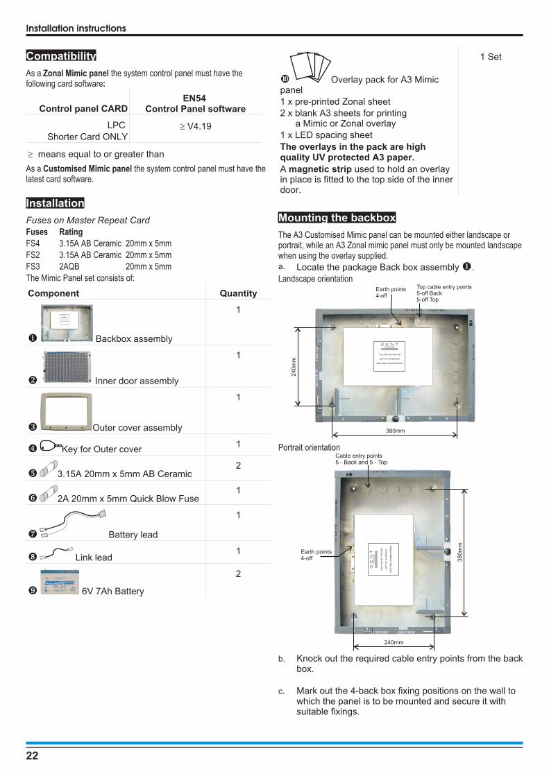
Compatibility
As a Zonal Mimic panel the system control panel must have thefollowing card software:
Control panel CARDEN54
Control Panel software
LPC
Shorter Card ONLY� V4.19
� means equal to or greater than
As a Customised Mimic panel the system control panel must have thelatest card software.
Installation
Fuses on Master Repeat Card
Fuses Rating
FS4 3.15A AB Ceramic 20mm x 5mm
FS2 3.15A AB Ceramic 20mm x 5mm
FS3 2AQB 20mm x 5mm
The Mimic Panel set consists of:
Component Quantity
� Backbox assembly
1
� Inner door assembly
1
� Outer cover assembly
1
� Key for Outer cover1
� 3.15A 20mm x 5mm AB Ceramic2
� 2A 20mm x 5mm Quick Blow Fuse1
� Battery lead
1
Link lead1
6V 7Ah Battery
2
� Overlay pack for A3 Mimicpanel
1 x pre-printed Zonal sheet
2 x blank A3 sheets for printinga Mimic or Zonal overlay
1 x LED spacing sheet
The overlays in the pack are highquality UV protected A3 paper.
A magnetic strip used to hold an overlayin place is fitted to the top side of the innerdoor.
1 Set
Mounting the backbox
The A3 Customised Mimic panel can be mounted either landscape orportrait, while an A3 Zonal mimic panel must only be mounted landscapewhen using the overlay supplied.a. Locate the package Back box assembly�.
Landscape orientation
Portrait orientation
b. Knock out the required cable entry points from the backbox.
c. Mark out the 4-back box fixing positions on the wall towhich the panel is to be mounted and secure it withsuitable fixings.
22
Installation instructions
by Honeywell
VIGILON FIRE SYSTEM
NOT YET IN SERVICE
AWAITING COMMISSIONING
Back box
Top cable entry points5-off Back5-off Top
Earth points4-off
380mm
24
0m
m
by Honeywell
VIGILON FIRE SYSTEM
NOT YET IN SERVICE
AWAITING COMMISSIONING
Ba
ck
bo
x
Earth points4-off 3
80
mm
240mm
Cable entry points5 - Back and 5 - Top
by
Ho
ne
yw
ell
VIG
ILO
NF
IRE
SY
ST
EM
NO
TY
ET
INS
ER
VIC
E
AW
AIT
ING
CO
MM
ISS
ION
ING

�Ensure the mains power is isolated to from the panel.
d. Terminate the loop and mains cables at the entry points and if required connect the cables to the appropriateterminals.
e. All the other parts are installed during commissioning.
External wiring
The external cables are routed into the back box using the cable entry points on the back box. The left 4 entry points are for the loop cables thatconnects to terminal block P16. The right cable entry point is for the mains cable which is connects to the terminal block P9.
� All the other parts supplied with the A3 mimic panel are fitted during the commissioning stage, however the procedures aredescribed here for completeness.
How to fit the inner door assembly
The following procedures describe how to fit the inner door assembly to the backbox.
Align the inner door assembly� to the two hinge pin positions� on the back
box� and slide the door down until it is seated correctly. Insert the top
(removable) hinge pin and secure it by rotating the pin into the back box.
Close the inner door assembly� and lock it using the fastners at position�.
For minor adjustment of the inner door, open the fixing screw� and adjust the
hinge plate� to a required position and then secure the plate to the backbox
by tightening the screw�.
23
Vigilon EN54 system
Inner door assembly
Hinge pin
Back boxassembly
Magnetic strip
Adjustable Hinge Plates
P9
L N
FS4
3.15A(T)mains fuse
01 L1 02 L20C LC
P16
Loop IN
Loop OUTFrom
Mains fused spur
Loop COM
Master Repeat Card01 L1 02 L20C LC P9L N
P17
DANGERWRITE PROTECT
L N
FS4P16
P4
RESET

Where to connect the internal cables
Remove the protective cardboard cover from the Master Repeat Card. Connect the earth lead� from the back box to the inner door assembly.
Connect the flat flexible cable to socket P13 on the Master Repeat Card , see details on fitting and remove of flat flexible cable.
How to fit the outer cover
Hook� the Outer Cover� over the top edge of the Back Box�. Close� the bottom of the Outer Cover onto the Back box and secure the
Outer Cover by the two captive screws on the cover using the key supplied.
Ensure the zonal mimic or customised mimic plan is located centrally within the anti glare window of the outer cover.
For full information see leaflet supplied with the product.
24
Installation instructions
Inner doorBack box
Fit earth leadfrom back boxto inner door
Connect the flatflexible cable frominner door to MRC
Master Repeat Card (MRC)
A
A
Outer Cover
Back box

Repeat Panel(loop connectable)
The repeat panel duplicates all of the control panel indications and theessential controls.
The repeat panel has its own mains derived power supply with battery forstandby power in the event of mains supply failure. A lockable front doorprevents unauthorised access to fire alarm controls but allows all of theindicators to be seen. The panel is designed for semi-flush or surfacemounting and facilitates both rear and top cable entry points.
This repeat panel can be installed on a loop circuit of the Gent Vigilon firedetection and alarm system. It can be sited near an entry or exit point ofa building and fit in with the loop cable routing.
Compatibility
The repeat panel is compatible with system control panel having cardand software listed below:
Control panelCARD
Control Panel Software
EN54 BS5839
LPCShorter Card
ONLY
� V4.19 � 3.90
� means equal to or greater than
Technical Data
Panel dimensions height 403mm, width 338mm,depth 101mm
Weight 9Kg with batteries (approximate)
Storagetemperature
-10 to 55ºC
Operatingtemperature
0 to 45ºC
Relative humidity(Non condensing)
Up to 90% temperature5 to 45°C
Battery 12V 7Ah sealed lead acid
Mains operatingvoltage
230V +10% -6% 50Hz
Emission BS EN61000-6-3 : 2001
Immunity BS EN50130-4 : 1996 : Part 4
LVD BS EN 60950-2006
Ingress protection IP31 (estimated)
Colour Door - Pantone 422Back box - Graphite Grey(RAL 7024)
Controls(with door closed)
Access level 1
Next and Previous buttonsoperable during fire conditiononly.
Control buttons(with door open)
Access level 2
Sound Alarms, Silence Alarms,Reset Fire, Cancel Fault Buzzer,Verify, F1-F4, Menu On/Off andU1-U4.
Indicators Fire, Verify, Power, Fault, PowerFault, System Fault, Delay andCB253/254.EN panel only: Sounder,Sounder, Delay, DisablementTest and 32-Fire Zone LEDs.
BS panel only: Commission andWarning.Display: 8 lines 40 charactersper line, back-lit LCD.
Loop connection 3-way connection to a loop circuit
EN54-17 dataFire detection andfire alarm systemshort circuit isolators
Vmax 42V Vnom 40V
Vmin 24V VSO max 16V
VSO min 8V IC max 0.4A
IS max 1A IL max 20�A
ZC max 0.1�
25
Vigilon EN54 System
Vigilon Fire SystemGENT 2007
Panel healthy15:45

Installation
The Repeat Panel Set consists of:
Parts Quantity
� Backbox assembly 1
� Outer door assembly 1
� Inner door assembly 1
� 20 Way ribbon cable 1
� 40 Way ribbon cable 1
� Spares pack (includes battery leads andmembrane labels for BS panel )
1
Battery 12V 7Ahr 1
Fuses on the Master Repeat Card
Fuse Rating
FS4 3.15A AS 20mm x 5mm
FS2 3.15A AS 20mm x 5mm
FS3 2A QB 20mm x 5mm
Back box mounting
a. Find the Repeat panel Back box � package andremove the temporary cover.
b. Secure the back box to the wall with suitable fixings. Ifthe backbox is to be semi-flushed then use the optionalsemi-flush surround.
c. Terminate the cable at the entry point leaving 400mmtail wire length.
� If mains supply cable ends are not required to beconnected then ensure the ends are insulated for safety.
d. Refit the temporary cover to protect the panel until allbuilding work is complete.
Doors, Cables and Power up
The doors and cables are installed after building work is finished.a. Remove the protective cover from the backbox.
b. Fit the inner door� to the panel enclosureremembering to connect the earth lead from thebackbox to the inner door. Fit the outer moulded door
� to the backbox.
c. Wiring the panel:
� Ensure the mains supply is completely powereddown before wiring the mains cable ends.
• connect the mains cable to terminal block P9 on theMaster Repeat Card.
• fit battery lead� supplied in the spares to connector P5on Master Repeat Card.
• connect the loop cables to terminal block P16 on theMaster Repeat Card.
• connect the 40 way ribbon cable� to the Master RepeatCard connector P2 and the other end to Display Key Cardon the top right edge connector - P1.
• connect the 20 way ribbon cable� to the Master RepeatCard connector P1 and the other end to Display Key Cardon the top right edge connector - P6.
d. Power-up is done during commissioning by the serviceorganisation and it involves switching ON the mainssupply and connection of battery leads. The Power upindications are:
• all the LEDs on the panel are lit for a short duration and apower up message displayed.
• the local buzzer sounds
• the display reads: Main panel is off Line
• the Fault and System Fault LEDs are lit.
26
Installation instructions
cL
310mm
115mm115mm
37
0m
m
28
5m
m
45
mm
Floor level
1.6
5m
Cable entry points
4-off - Back and 4-off - Top3-off
Earth points
BackboxFixing centres
4-off
01 L1 02 L20C LC P9L N
P17
DANGER
BT
+B
T-
+RS485
0V 24V-
WRITE PROTECT
BUZZERDISABLE
P8
DANGERDO NOTREMOVE
L N
P5
FS2
FS4P16
P4
P2
P1
SW3
PB2
WD1P14P7USB
FS32A(QB)
RESET
DANGER
WARNINGRemoval of
cover exposeslive parts.
Repeat Panel
Cross section of
the wall to which
the panel is to be
semi-flush mounted
5mm diameter
fixing holes
Aperture Height:380mm
Aperture Width: 320mm
Aperture depth should not be
less than: 59mmRepeat panel
semi-flush surround

27
Vigilon EN54 system
40-wayribbonto DKC
12V 7Ah battery
Earth toInner door
3.15A(T)mains fuse
01 L1 02 L20C LC
P16 P9
L N
20-wayribbonto DKC
Red
Black
Inner and outerdoors not shown
Loop IN Loop OUT From Mains fused spur
FS4
3.15A(T)mains fuse
FS2
3.15A(T)Ceramic
(Anti Surge)
Battery Fuse
Loop COM
Master Repeat Card01 L1 02 L20C LC P9L N
P17
DANGER
BT
+B
T-
+RS485
0V 24V-
WRITE PROTECT
BUZZERDISABLE
P8
DANGERDO NOTREMOVE
L N
P5
FS2
FS4P16
P4
P2
P1
SW3
PB2
WD1P14P7USB
FS32A(QB)
RESET
DANGER
WARNINGRemoval of
cover exposeslive parts.
mains electricalsupply
Loop OUT
Previous Next
Spur Connection
XXXXX --- Fire Alarm SystemGENT 2009
Designed to EN54 Pt 2 & 4
Panel healthy 15:45
1 2 3 4 5 6 7 8 9 10 11 12 13 14 15 1617 18 19 20 21 22 23 24 25 26 27 28 29 30 30 32
Zones
Fault
System Fault
Delay
Test
Fire
Power
Power Fault Verify
Disablement
Sounder
Loop IN
Repeat panel
CB1
CB2

Repeat Indicator panelThe repeat indicator panel provides messages and indications of systemevents and it connects directly to the Vigilon fire panel.
Technical data
Dimensions in mm height 177 x width 206 xdepth 48.5
Full assembly weight 750g
Storage temperature 0 to 60ºC
Operatingtemperature
0 to 45ºC
Relative humidity(Non condensing)
up to 90%Temperature 5 to 45°C
Ingress protection IP30 estimated
Colour White
Indicators Fire, Fault, Disablement,Power On, System fault,Sounder2 line 20 character per line,back-lit, display.
Controls(with flap closed)
Test and Cancel buzzer
Controls(with flap open)
Fire, Fault, Disablement,Warning, Display Mode andNumeric keypad.
� If only one repeat indicator panel is to be connectedto the control panel then make use of the 24V supply at thepanel, there is no need to use an external power supply
Cable
� Belden No. 9842 EIA RS485 Applications, O/A Beldfoil®Braid 1Km maximum cable distance from the control
panel to the last repeat indicator panel must have followingcharacteristics:
• Two twisted pairs
• 24AWG (7 strands x 32 AWG) conductors
Installation
a. Open the outer cover.
b. Insert the external cable into the backbox assembly atthe required entry point.
c. Mark the fixing points and secure the backbox to thewall.
d. Connect the cable to terminals.
e. Refit the front cover and flap.
28
Installation instructions
1 2 3
4 5 6
7 8 9
0
+
RE
L
-
24
V
ab
RS
48
5
ON
1 2 3 4 5 6 7 8
J6 J5 J7
Back cable entry pointThinned sectionson sides of enclosure forcable entry 4 enclosure fixing points
PANEL
TERMINAL CARD
Terminals P4 is PORT 1
REPEAT INDICATOR PANEL 1
a
bRS485
earth
REPEAT INDICATOR PANEL 4
-
+24V
a
bRS485
earth
UP TO 4 REPEAT INDICATORPANELS MAXIMUM
POWERSUPPLY UNIT
+ -
-
+24V
24V
P4RS485
A 5V B 0V

S-Quad Sensors
This following is information on the S-Quadproduct range. The S-Quad product integratesdual angle smoke, heat and carbon monoxidegas detection with electronic sounder, speechand LED flasher (Strobe) in one assembly.
General specification
Operating voltage 35V - 41V
Weight 110g
with base - 170g
Dimensions 117mm diameter by 49.6mmheight
With base the heightincreases to 63.8mm
IP rating IP30IP20 when mounted on ametal back box
Enclosure ABS
Colour RAL 9010
Approval LPCB approved
Storage Temperature -20�C to 70�C
(for S-Quad with CO -20�C to
50�C)
Ambient operatingtemperature
-10�C to 50�C
Relative Humidity 95% non condensing(5°C to 45°C)
Heat (H) Standard EN54 : Part 5
Optical (O) Standard EN54 : Part 7
Dual Optical (O2)
StandardEN54 : Part 7
Sounder (S) Standard EN54 : Part 3
Gas (CO) Standard * LPS 1274
Multi sensor standard CEA 4012
* The 'Gas' sensing is designed to meet the requirements of LPS 1274
Information on minimum sound output levels to include polar dispersionis covered in a technical note TECH7018.033, available on request frommanufacturer. Information on minimum sound output levels to includepolar dispersion is covered in a technical note TECH7018.033, availableon request from manufacturer.
Base
The base has terminals for external cables to allow it to be electricallyconnected to the panel loop circuit and to the monitored input or outputcircuit. Any S-Quad device can be plugged into an S-Quad base.
Base Gasket
The optional foam rubber base gasket S4-BASE-GASKET can be fittedto the base to prevent water damage from dripping water from theceiling.
Base labels
An optional label S4-BASE-LABEL can be fitted to the base. The labelcan be marked up with device location information.
Indicators
The S-Quad has a red LED that gives an indication in the event of a fire.The LED can be configured to flash periodically, as an 'in operation'confirmation, this indication is given system-wide at all S-Quads. TheS-Quad with a CO sensor also has a blue LED to indicate when a firesignal senses the presence of CO.
Dust Cover
A dust cover is supplied with the S-Quad, to prevent dust from buildingwork contaminating the sensor. The cover is removed prior to thecommissioning of the fire alarm system.
Do's and Don't
�DO NOT locate smoke detectors where products ofcombustion may be present such as kitchens, garages,furnace rooms, welding shops etc.
DO NOT locate heat detectors above boilers or heaters orwhere the temperature is normally very high or liable tosudden fluctuations.
DO NOT locate smoke or heat detectors: -• In dusty or dirty environment.• Near heating or air-conditioning grilles.• Outdoors in stables, sheds etc.• In excessively damp areas.• In dead air spaces at the junctions of
ceilings and walls.• At ceiling locations where a ‘thermal
barrier' may exist.DO NOT locate a CO detector: -
• In buildings where farm animals are kept.• In excessive damp areas.• In battery room where non sealed battery
are kept.• In a Car park where exhaust fumes will
be present.Follow recommendations detailed in section 22of BS5839 : Part 1 : 2002
29
Vigilon EN54 System

Siting
A S-Quad device plugs into a dedicated Base that is installed in theprotected premises. The Bases should be sited in locations as defined bythe project plans and by BS5839 : Part 1 : 2002.
Metal back box
A metal back box must be used for base or semi-flush mounting. Theearth continuity must be maintained throughout the whole loop. The earthmust be securely connected to the back box.
In - Out wiring to S-Quad bases
Programmable input/output
� The 34703 Slave Relay unit and 34703 Slave LEDindicator unit are NOT supported for use with S-Quad firesensors. The Slave units are only compatible with 34xxxrange of fire sensors.
All S-Quad devices can be configured as either monitored input orunmonitored output. The factory setting of the programmable input /output is unmonitored output, to drive an external repeat LED without aseries resistor.
There is a maximum cable length limit of 15 metres from the S-Quadbase to the external I/O Unit.
The input can accept signals such as fire, non fire or fault, these areconfigured during commissioning. As a fire input it is possible to connecta conventional Manual Call Point (non UK application only) with a seriesresistor of value 470 Ohms coupled with an end-of-line 10Kohmsresistor. In this case the fire input is fully monitored for open or shortcircuit faults.
The input can be setup as a non-fire or fault input using a similararrangement with series and parallel resistors as shown. It is possible forsuch an input to trigger a command that is configured to action an outputelsewhere in the system to control plant equipment such as theventilation system.
30
Installation instructions
EM2OUT5
IN4C3
L10V
L2
+
-
+ -
Unmonitored LED output
+ -
Remote LED unit13449-01
+-+-
+-+-
EM2OUT5
IN4C3
L10V
L2
47
0�
10
K�
InputBeam Transmitter base
FIRE
keyswitch
O
I
Active
O
I
Normal
O
I
EM2OUT5
IN4C3
EM2OUT5
IN4C3
L10V
L2
L1
0V
L2
LOOP CABLE
STANDARD 60mm METAL BACK BOX
CABLE GLAND
LOOP CABLE
S-QUAD BASECEILING TILE
2 SCREWS TO SECUREBASE TO METAL BACK BOX
CROSS SECTIONOF CEILING TILE
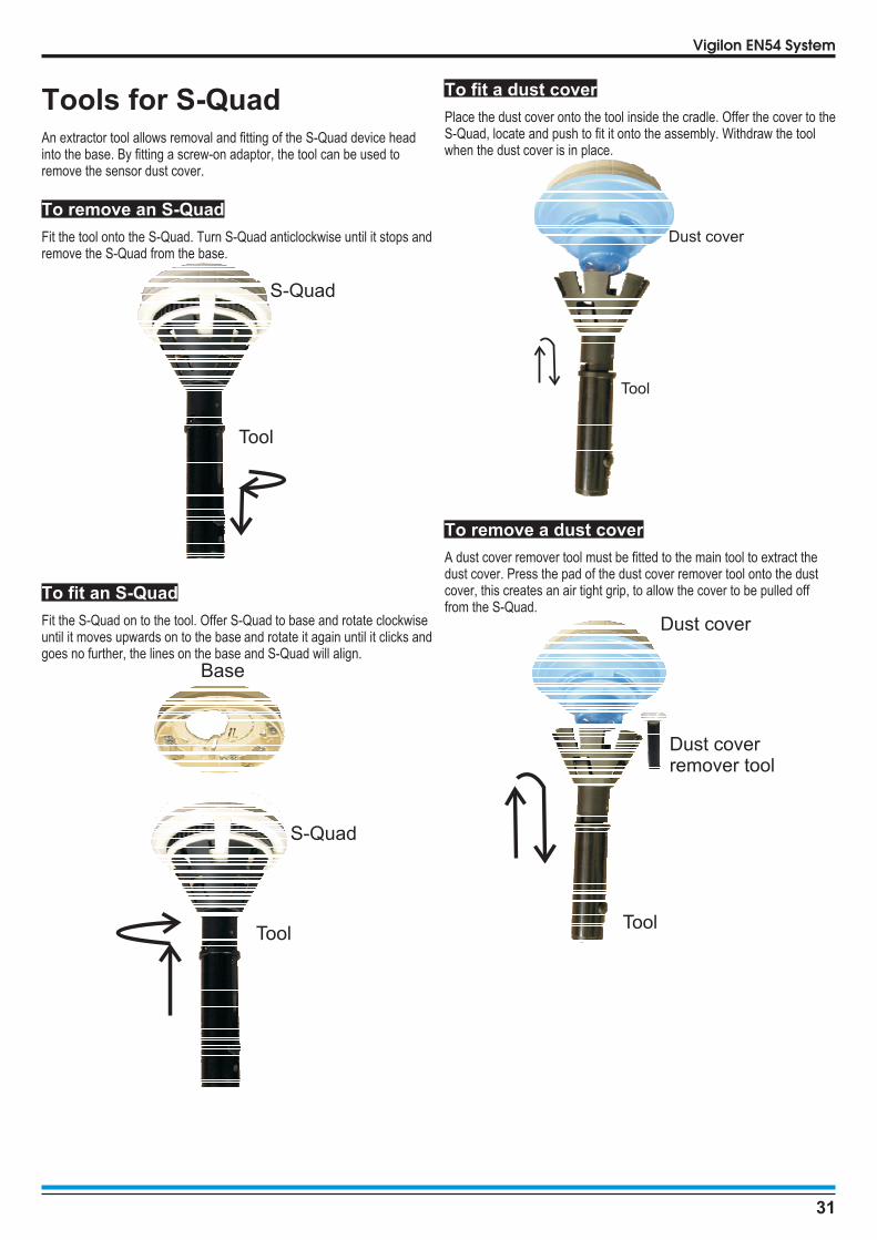
Tools for S-QuadAn extractor tool allows removal and fitting of the S-Quad device headinto the base. By fitting a screw-on adaptor, the tool can be used toremove the sensor dust cover.
To remove an S-Quad
Fit the tool onto the S-Quad. Turn S-Quad anticlockwise until it stops andremove the S-Quad from the base.
To fit an S-Quad
Fit the S-Quad on to the tool. Offer S-Quad to base and rotate clockwiseuntil it moves upwards on to the base and rotate it again until it clicks andgoes no further, the lines on the base and S-Quad will align.
To fit a dust cover
Place the dust cover onto the tool inside the cradle. Offer the cover to theS-Quad, locate and push to fit it onto the assembly. Withdraw the toolwhen the dust cover is in place.
To remove a dust cover
A dust cover remover tool must be fitted to the main tool to extract thedust cover. Press the pad of the dust cover remover tool onto the dustcover, this creates an air tight grip, to allow the cover to be pulled offfrom the S-Quad.
31
Vigilon EN54 System
Base
S-Quad
Tool
S-Quad
Tool
Tool
Dust cover
Tool
Dust coverremover tool
Dust cover

S-Quad Semi-flush fixingkit (S4-FLUSH)An S-Quad device can be semi-flush mounted to a ceiling tile to a depthof the approximate 20mm, which is slightly deeper than the baseassembly. To semi-flush mount a special housing must be used, whichconsists of a main assembly and a trim ring.
� There is an enhanced volume output of sound andspeech from a semi flush mounted S-Quad.
Technical data
Weight 164g with trim ring
Dimensions 174mm diameter by 50mm depth
Enclosure ABS
Colour RAL 9010
StorageTemperature
-20�C to 70�C
Ambienttemperature
-10�C to 50�C
Relative Humidity 95% non condensing(5 to 45°C)
32
Installation instructions
S-Quad
Trim ring
Cross sectionof Ceiling Tile
Semi-Flush shroud
S-Quad Base
Do not over tighten the clampingscrews as this will cause theclamps to cut into the ceiling tile.
Metal back box
Cut a 140mmdiameter hole in theceiling tile.(
)
If required use a Bi-Metal Holesaw140mm or 146mm, fromwww.shop4tools.co.uk
Insert the semi-flush shroudassembly into the holein the ceiling tile.
Hold the semi-flush shroudto the ceiling tile and tightenthe three screws to splay theclamps to secure the shroud to the tile.
Locate the S-Quad Base intothe semi-flush shroud, such that thetwo locating pillars on theshroud feeds through the twoelongated holes on the Base.Push the Base into the shrouduntil the Base click locks intothe shroud.
Offer the trim ring to the shroudand slowly rotate ring clockwise until itclicks and goes no further. This willlock the ring in position.
Fit the metal box onto the backof the semi-flush shroud using theappropriate fixing screws to securethe box to the flush shroud.
Offer the S-Quad to the Baseand rotate the S-Quad clockwiseuntil it moves upwards into Base,and then rotate the S-Quad againuntil it clicks and goes no further.
Make the cable connections.
Clamp

Beam Sensor
Transmitter (red retainer) Receiver (black retainer)
� Beam sensor pair (Transmitter & Receiver)
� Beam Transmitter only
� Beam Receiver only
� Angle bracket with base
� Parallel bracket with base
� Light Shield (5 per pack) Test Cards
The Beam Sensor pair allows the detection of smoke over distances from2 m to 100 m, using a 'beam transmitter' and a 'beam receiver', eachmounted on a base fixed to either bracket.
Technical Data
Standards -designed to meet
EN54 : Part 12 : 2002EN54 : Part 17 : 2005
Approval LPCB Approval pendingSTATES 0, 1, 2 and 3
Overallassembleddimensions in mm
Transmitter or receiver:
� 117 x d 54Angle bracket with base:h 145 x w 106 x d 130Parallel bracket with base:
� 152 x d 27
Light shield: � 50 x 75
Assembled weight(approximate)
Transmitter or receiver:105gAngle bracket + base: 620gParallel bracket + base: 600gLight shield: 14g
Enclosure ABS
Colour (Sensor) RAL9010
Storagetemperature
-20 to 70ºC
Ambient operatingtemperature
-10 to 50°C
Relative Humidity(Non condensing)
up to 95%
Temperature 5 - 45°C
Emission BS EN61000-6-3: 2007 EMC forresidential, commercial & lightIndustry.
Immunity BS EN50130-4: 1996 + A1:1998 + A22003 for alarm systems
Ingress Protection(estimated)
IP30IP20 mounted on bracket
Operating voltage 35-41V
Indicators Two Red and Seven Green LEDsvisible at 500LUX ambient light levels5m
EN54-17 : 2005(section 4.8)data:
Vmax 42V IC max 0.4A
Vnom 40V IS max 1A
Vmin 24V IL max 20�A
VSO max 16V VSO min 8V
ZC max 0.130�
Compatible Panel : MCC � V4.41 / V3.96
LPC � V4.39 / V3.96
33
Vigilon EN54 System
Base
Sleeve

Do's and Dont's
A general guidance on Do's and Dont's is illustrated here, however for full information on siting beam sensor pair refer to BS5839 Part 1.
34
Installation instructions
IR Beam(invisible)
Solid Wall
Floor level
IR Beam projection
Solid Walls
Plan view (flat ceiling)
Receiver
Receiver
Transmitter
Transmitter
Transmitter Receiver
Shelves and Storage boxes
Solid Wall
Floor level
Ceiling
Building structure support
Solid Wall
Floor level
Ceiling Ventilation duct
0.3m - 0.6m
15m
> 0.15m
Metal Ceiling
Unistrut
25m maximum
15m
2m to 100m maximum
1m minimum7m maximum
Solid Walls
Plan view (flat ceiling)
Receiver
Receiver Transmitter
Transmitter
15m
3m max.
> 0.5m
ReceiverTransmitter
ReceiverTransmitter
ReceiverTransmitter
Metal beam
Solid Wall
2.5 m
17.5 m width
17.5 m width covered by one beam sensor pair within 600mmvertical of the apex, using the extra coverage of 25% givenby the roof angle of 25
o
25o
1.25 m
10
mm
ou
ntin
gh
eig
ht
20
m
600mm
Calculated from12.5% of 10mmounting height
Seven beam sensorpair requiredat this height
2.5 m calculated fromtwice 12.5% of 10mmounting height
ATRIUM
Side view (flat ceiling)
Obstructions
Cladding panels / Plaster board
Transmitter
Transmitter
Receiver
Glass Atrium
Heat Source
Receiver
Horizon
Sunlight or Strong light source
Horizon
Sunlight or Strong light source

Test Keyswitch
A test keyswitch unit can be connected to the 'beam transmitter' to facilitate simulation of a test fire condition. The keyswitch unit is required to have
a series resistor of value 470� coupled with an end-of-line 10K� resistor wired as illustrated below.
There is a maximum cable length limit of 15 metres fromthe 'beam transmitter' base to the external KeyswitchUnit.
A keyswitch input at the 'beam transmitter' must beenabled during commissioning.
The wiring is monitored for open and short circuit failure.
On operating the keyswitch it will cause a ramp downsignal to generate a test fire condition.
How to install an Angle bracket and fit a Beam sensor
The installation of the angle bracket and beam sensor are illustrated by steps� to �. Note steps� and� require setting of adjusters forsensor to face the opposite sensor assembly, which is normally done during commissioning.
35
Vigilon EN54 system
EM2OUT5
IN4C3
L10V
L2
47
0�
10
K�
InputBeam Transmitter base
FIRE
keyswitch
O
I
Active
O
I
Normal
O
I
L1
0V L2 0V
L1
(1)
0V
(4)
0V
(2)
L2
(3)
EA
RT
H(5
)
The numbers in bracketsrefer to alternative cablesleeve markings which maybe used to denote wires.
Metal box
Earth
Cable from the sensor base
Loop - In cable Loop - Out cable
Angle bracket with base
Metal boxmounted ona solid wall
Beam Sensor
Keyswitch wiring if used
The Test Keyswitchconnects to terminalsEM2 and C3 in thebase.

How to pre-assemble the parallel bracket
The parallel bracket may be pre-assembled as illustrated by steps� to�.
How to install a Parallel Bracket and fit a Beam sensor
The installation of the parallel bracket and beam sensor are illustrated by steps� to�.
Further information about this product can be found in Part 2 of this document available form your supplier.
36
Installation instructions
THIS WAY UP
Pre-assembledParallel bracket
Metalbox
Beam SensorBase
EM2OUT5
IN4C3
L10V
L2
LOOP IN
LOOP OUT
Loop CableIn - Out
Test Keyswitch wiring if used
The Test Keyswitchconnects to EM2 andC3.
SleeveEnsure the base is mounted to the bracket suchthat the Beam sensor LEDs can be seen from floor level.
ARROW
Fixed plate
Adjustable plate
Adjuster
Bush
Lock nut
Bush
Spring
8m
m
8m
m
Ensure the adjusters are set to provide an 8mmgap all around between the adjustable and fixed plates.

Duct kit
The air duct kit is used in combination with different Venturi tubes andspecial S-Quad fire detector for the surveillance of air ducts in buildings.
The kit is fastened to the outside of the air duct. The Venturi tube is leadinto the duct through a hole drilled for this purpose. The air streamingthrough the air duct is picked up by the Venturi tube and led via thedeflecting unit inside the housing directly to the detector for subsequentevaluation.
The inserted fire detector is directly connected to the analog loop of theFire Alarm System. The operation and indication of alarm and faultmessages is given at the connected fire alarm panel.
Venturi tubeThe Venturi tube are available in various lengths.
Length (mm) 600 1500 2800
Weight 0.2Kg 0.6Kg 1.2Kg
Technical date
Sensor and base
Operating voltage 35V - 41V
Weight S4-720 only:88g (with base - 148g)
Dimensions 117mm diameter by 49.6mm height(With base the height increases to63.8mm)
IP rating IP30IP20 when mounted on a metalback box
Enclosure ABS
Colour RAL 9010
Approval LPCB approved
StorageTemperature
-20�C to 70�C
Ambient operatingtemperature
-10�C to 50�C
Relative Humidity 95% non condensing(5°C to 45°C)
Optical sensor (O)Standard
EN54 : Part 7 : 2000
EN54-18 : 2005
EN54-17 : 2005(section 4.8)data:
Vmax 42V IC max 0.4AVnom 40V IS max 1A
Vmin 24V IL max 20�A
VSO max 16V ZC max 0.1�VSO min 8V
Housing
Dimensions(W x H x D) in mm
180 x 235 x 183
Terminals 1.5 mm² max.
Air velocity 1 m/s to 20 m/s
Full Assemblyweight
Approx. 800g (without sensor andbase)
Storagetemperature
-15 °C to +65 °C
Operatingtemperature
-10 °C to +60 °C
Housing ABS plastic
Colour grey (with transparent cover)
Immunity BS EN50130-4: 1996: Part 4Alarm systems
Ingress Protection IP54
Colour White
For full instructions see the leaflet supplied with the product.
37
Vigilon EN54 System

S3
Speech, Sounder Strobemark IIThe low power addressable Voice Enhanced Sounder and combinedStrobe products provide audible and visual alarm signals, and aredesigned for use in Gent analogue and addressable fire alarm systems.
The S3 devices are supplied with standard speech messages along withsounder and strobe option. The devices are configured duringcommissioning to operate to site specific requirements. The devices aresupplied with either a deep base (40mm) or a shallow base (25mm),offering IP55C and IP31C ratings respectively, with the exception of thesystem range (see diagram below) which is available with deep baseonly.
The S3 product range incorporates innovative design features protected by
Patents GB2388994, GB2388995 and GB2388916. The product design has
also been registered.
� If you have a speech/sounder only product thenignore the strobe information given.
Speech messages
MessageNo
Speech message
Message 2 Attention please this is an emergencyplease leave the building by thenearest available exit. (female voice).
Message 3 An incident has been reported in thisbuilding please await furtherinstructions. (female voice).
Message 4 This is a test message no action isrequired. (female voice).
Message 5 This is a fire alarm! Please leave thebuilding immediately by the nearestavailable exit. (male voice).
Tone No. Description of tone.
Message 1 Alarm Bell (equivalent to 8" SolenoidBell) 106dBA @ 1m.
� The addressable S3 products are fully synchronisedon the same fire panel.
Technical data
Sound output for standardtone (levels given aretypical values with
measurement taken at 90�anechoic - fast response)
Low profile S3
- 100dBA+/-3dBA
System S3
- 103dBA+/-3dBA
Standard (sounder only) EN54 : Part 3
Messages, Tones andStrobe flash rate
see instructions supplied withthe product
Strobe light output withred lens
equivalent to 3W Xenonflasher
Operating voltage range 35V to 41V
Terminal size 2.5mm2
maximum
IP rating with deep base
with shallow base
IP55C
IP31C
Enclosure colour White and Red (with redtranslucent lens cover fitted tounit with Strobe).
Enclosure material Flame retardant ABS (Strobecover is polycarbonate) Theplastic enclosures meet theflammability requirements ofISO 1210:1992 Class FH-2.
Weight 0.3Kg (approximate).
Operating temperature -10�C to 50�C
Storage temperature -20�C to 70�C
Relative humidity(non condensing)
up to 90%
IR operating distance(to select volume level)
3m
Message and attentionTone period
10 seconds defaultConfigurable up to 60seconds
38
Installation instructions
Low profile S3
System S3
Available in deep or shallow base Available in deepbase only
40
112
90
60
25
75
75
112
with shallow base
35
with deep base
with deep base
120 DIA

Installation
a. Drill or knockout the required cable entry points on thebase.
b. If using the deep base option and IP55C protection isrequired, then stick the circular wall gasket on to thecentre back of the base.
c. Secure the base to the wall whilst ensuring Top of thebase is in correct orientation.
d. Terminate the cable at the entry point leaving no morethan 10cm (4") tail wire length for connection.
e. Ensure the transparent cover is in place over thePCB. Connect the wires to the terminal block.
f. Close the main assembly to the base.
Retrofitting a System S3
deviceA system S3 Mark I device can be retrofitted to an alarm sounder base.The existing base having a terminal block to which loop cables areconnected.
39
Vigilon EN54 System
TOP
Infraredreceiver
Main assembly
# Locating pegsfor the transparent cover
#
#
PCB
Label
Transparentcover
Adhesive spot usedto secure the transparent cover
02
L2
0C
LC
01
L1
P16
P6
D4
Connector used to program the device(Programmable base required)
Adhesive spot usedto secure the transparent cover
LC
0C
L1
01
L2
02
LC
0C
L1
01
main assembly
L2
02
base
S device (3-way)3
red
black
red
black
red
black
Loop INLoop OUT
COMMON LINEto Spur
Ensure the terminal blockis placed inside the back of the base
112
50
60
35
25mm depth
40mm depth
Shallow base
Deep base
Top
Top
Cable entry1- Back
112
BaseGasket
Thinned sectionfor IR receiver
Thinned sectionfor IR receiver
EarthcontinuityStrap
Cable entry2 - Top1 - Bottom1 - Back
WallGasket
DO NOT FLUSHMOUNT THE BASE.

Environmentally protectedHeat SensorThis unis has IP55 rating as specified in the British StandardBS 5490:1977 which is the specification for classification of degree ofprotection provided by enclosures.
a. Remove the front cover of the unit disconnecting anyflying leads attached to the terminal block.
b. Place the unit in the desired position and mark the fourfixing holes. When the product is mounted ensure thepre-machined cable entries are at the bottom.
c. Drill the four fixing holes and mount the unit.
� When using PYROTENAX cable, the cables MUST beterminated using PYROTENAX glands (Code No. RGM 2L1.5),screw-on seals (Code No. RPS 2L1.5) or equivalent and astandard M20 locknut.
d. Feed the cables into the unit. Ensure that the sealingwasher supplied is fitted between the cable gland andthe unit (rubber part of the washer against the unit).Use the earth continuity straps provided to maintainloop cable earth continuity.
e. Connect the earth tails into the earth termination point.
f. Terminate the cable at the entry point and connectends into the appropriate terminals on the sealedprinted circuit board module, see connection diagram.
� Failure to promptly replace the cover will resultin environmental damage.
g. Reconnect the flying leads from the cover into theappropriate terminals on the sealed printed circuitboard module. Refit the cover to the unit. Formaximum protection ensure that the cover screws aretight and secure.
� Forcing the cover to fit the wrong way round willdamage the unit.
Heat Probe
For carriage purposes the probe on the heat sensor is fully retracted. Itis important that the heat probe is positioned correctly. There should bea minimum of 20mm of the probe protruding from the front face of theprobe gland. The probe gland can only be tightened up once, as thegland uses an olive joint which should be replaced rather thanre-tightened. Once the probe is in the correct position the gland has tobe tightened finger tight plus 11/2 turns.
General data
Dimensions height 180 mm x width 180 mm xdepth 130 mm.
Storagetemperature
-30 to 70ºC
Operatingtemperature
0 to 50°C
Ingress Protection IP55 estimated
Case ABS engineering plastic.
Indication Red LED that illuminates when theactive.
Operating voltage 20 to 50V
40
Installation instructions
Heat sensor
LIN
E1
0V
OLT
S
LIN
E2
0V
OLT
S
LE
D+
LE
D-
TH
+
TH
-
TH
ER
MIS
TO
RP
RO
BE
(ON
CO
VE
R)
LE
D(O
NC
OV
ER
)
LO
OP
OU
TT
ON
EX
TD
EV
ICE
LO
OP
INF
RO
MP
RE
VIO
US
DE
VIC
E
Cable entry points
160mm
16
0m
m
Earthterminals
EP product with cover removed
LIN
E2
0V
LIN
E1
0V
RE
D
BL
AC
K
AN
Y
AN
Y

Manual Call Points
Options
� Manual Call Point (Glass)
� Manual Call Point (Glass) with Protective cover
� Manual Call Point (Resettable element)
� Manual Call Point (Resettable element) with Protectivecover
Glass or Resettable element options
Optional Back box
The optional back box has recessed centres 'D', 3 at the top and 1 at thebottom, a maximum of 2 are usable.
Technical data
Standard EN54: Part 11: 2001
Dimensions height 88 mm x width 88 mmdepth 21 mm or 57 mm whensurface mounted
Full assembly weight 110g - approximate
Storage temperature -30 to 70ºC
Operatingtemperature
-25 to 70°C
Relative Humidity(Non condensing)
up to 95%Temperature 25 to 55°C
Emission BS EN61000-6-3:2001 Residential,Commercial & Light Industry ClassB limits
Immunity BS EN50130-4: Part 4 :1996
Ingress Protection IP43 estimated standard type
IP55 estimated with protective coverand back box
Colour Red (similar to RAL3020)
Case ABS engineering plastic
Indicators
Normal
Active
Green LED for status and finddevice application
Red LED and Yellow tab for activeor Fire indication
Testing The operation of the MCP is testedby using a test key
Terminals 2.5mm2maximum
Approval LPCB Approved:S4-34842 and S4-34800
Operating voltage 35V to 41V
Installation
a. Check the contents of the package:
Component Quantity
Call point assembly 1
Earth Strap 1
Test Key 1
Long Screw 2
b. The call point assembly may be mounted on astandard electrical box or on the optional red back boxS4-34895.
c. Feed the fire rated cables through the entry holes andmount an electrical box or the red optional back box toan even wall surface using suitable fixing.
� When semi flush fixing the call point assembly astandard electrical box must first be flushed into the wall beforethe call point assembly is fitted.
41
Vigilon EN54 System
87
87
C
15
21RemovableTerminal block
A
Glass
Top
B
Resettable element
Top
36
THIS WAY UP
50
88
43,5
18,5
D
D
88

d. Terminate each cable entry at the back box. Use the earth strap or the earth point in the back box to maintain loopcable earth continuity. Connect the loop cable to the terminals.
e. Disengage front cover from the call point assembly using the end of the test key 'E' and lift out the cover from thebottom edge.
f. Secure the call point assembly to the back box using the 2 long screws supplied.
g. To re-assemble the glass or resettable element, using the test key turn the tab to position 'F' and insert the glass 'A'or optional resettable element 'B'.
h. Hook the front cover onto the top edge of the call point assembly and then push the bottom edge down until it clickshut. Check both hooks on the top of the front cover are locked onto the call point assembly.
i. Turn the test key anticlockwise to position 'G' (not visible) such that the glass or optional resettable element is heldunder the yellow arm.
j. Where applicable, ensure the protective cover 'H' is securely fitted to the call point assembly.
42
Installation instructions
E
F G
H
1IN
2O
UT
4C
Keyswitch assembly
LoopIn
LoopIn
1IN
2O
UT
34C
Manual Call Point
LoopOut
LoopOut
3

Keyswitch Interface / MCP
The keyswitch units covered in this leaflet are suitable for installation inGENT analogue addressable fire alarm system. The product rangecovered here include:
� Keyswitch MCP (Red)
� Keyswitch Interface (Blue)
� Spare Keys (Pack of 2)
� Surface Back Box for InterfaceRed Plastic (Pack of 10)
Keyswitch assembly
Back box
The back box has recessed centres 'D', 3 at the top and 1- at the bottom,a maximum of 2 are usable.
Technical data
Standard EN54: Part 17
EN54: Part 18
Dimensions height 88 mm x width 88 mmdepth 32mm or 66mm whensurface mounted
Full assembly weight 128g - without backbox192g - with backbox
Storage temperature -30 to 70ºC
Operatingtemperature
-25 to 70°C
Relative Humidity(Non condensing)Temperature25 - 55°C
up to 95%
Emission BS EN61000-6-3:2001 Residential,Commercial & Light IndustryClass B limits
Immunity BS EN50130-4: Part 4 :1996
Ingress Protection IP43 estimated standard type
Colour Red (similar to RAL3020)Blue (similar to RAL5015)
Case ABS engineering plastic
Indicators Normal
Active
Green LED for status and finddevice application
Red LED for active or Fire indication
Terminals 2.5mm2maximum
Operating voltage 35V to 41V
EN54-17 data Vmax 42V
Vnom 40V
Vmin 24V
VSO max16V
VSO min 8V
IC max 0.4A
IS max 1A
IL max 20�A
ZC max 0.1�
43
Vigilon EN54 System
Red enclosurefor Fire applications(supplied with backbox)
Blue enclosurefor Plant interface applications(supplied with backbox)
I I
8815
32
RemovableTerminal block
O
I88
36
THIS WAY UP
50
88
43,5
18,5
D
D
88

Installation
a) Check the contents of the package:
Component Quantity
Keyswitch Interfaceassembly (red / blue)
1
Earth Strap 1
Operating Key 2
Opening Key 1
Long Screw 2
Instruction leaflet 1
Blue Back boxsupplied with Bluekeyswitch interfaceassembly
1
b) The keyswitch assembly may be mounted on astandard electrical box or on the backbox.
c) Feed the fire rated cables through the entry holes andmount an electrical box or the red/blue back box to aneven wall surface using suitable fixing.
� When semi flush fixing the keyswitch assembly astandard electrical box must first be flushed into the wall beforethe keyswitch assembly is fitted.
d) Terminate each cable entry at the back box. Use theearth strap or the earth point in the back box tomaintain loop cable earth continuity. Connect the loopcable to the terminals.
e) Disengage front cover from the keyswitch assemblyusing the end of the opening key 'E' and lift out thecover from the bottom edge.
f) Secure the keyswitch assembly to the back box usingthe 2 long screws supplied.
g) Hook the front cover onto the top edge of the keyswitchunit and then push the bottom edge down until it clickshut. Check both hooks on the top of the front coverare locked onto the keyswitch assembly.
Operation
To operate the keyswitch insert the operating key into the keyhole 'J' andturn clockwise to the stop position, the red LED 'K' is flashing. The greenLED 'I' gives an operating indication.
Apply the reverse procedure to return the keyswitch to a normaloperating position.
Label
When using the blue keyswitch interface to control plant ensure the unitis labelled to describe what is being controlled by the keyswitch.
It is suggested that an A4 sheet white paper label 32 x 12mm is used,such as the one from RS, part number RS495 385. The required text canbe printed onto the label. The label is stuck centrally inside the aperturebehind the transparent cover. Ensure LEDs remain visible and are notcovered by the label.
44
Installation instructions
E
i
THIS WAY UP
1IN
2O
UT
4C
Keyswitch assembly
LoopIn
LoopIn
1IN
2O
UT
34C
Manual Call Point
LoopOut
LoopOut
3
I JK
Normal
Active
O
I
O
I
O
I
DisableZone n
32 x 12mmstick on label
Transparent cover

These instructions cover the above interface modules and accessories.The S4 interface modules are designed for use with any Vigilon firealarm control panel. Each module includes a loop isolator for deviceisolation. Each module use one of 200 available device addresses on aloop and responds to regular polls from the control panel reporting thetype of device and the status (open/normal/short) of its supervised inputcircuit(s).
Features
� Analogue addressable communications
� Built-in type identification automatically identifies thesedevices to the control panel
� Reliable communication technique with high noiseimmunity
� Soft or SAFE addressing
� Common mounting options including surface mount,panel mount and DIN rail mount
� Dual-colour LEDs
� Plug-in terminal connections for ease of wiring
� EN54-17:2005 and EN54-18:2005
Cables
The cables recommended for wiring the input / output lines are the sameas those used for loop wiring, see instructions supplied with the firecontrol panel.
Installation
The S4 interface modules can be mounted in other equipment housingsusing the DIN rail mount brackets (S4-34491). A module can also befitted into a plastic box (S4-34490) or metal box (S4-34492). The boxeshave cable termination points on the enclosure.
45
Vigilon EN54 System
S4-34410S4 1-Input InterfaceModule(low voltage)
S4-34420S4 1-Output &1-Input InterfaceModule (low voltage)
S4-34450# S4 4-Input / OutputInterface Module(low voltage)
L1
L2
0V
0VC
ha
nn
el1
Ch
an
ne
l2
Ch
an
ne
l3
Ch
an
ne
l4
L1
L2
0V
0V
NCIn
pu
t
L1
L2
0V
0VIn
pu
t
CO
M
NO
Output
S4-34490Plastic box
1- End-of-lineCapacitor unit
2- 10K Resistors
2- 10K Resistors 1- End-of-lineCapacitor unit
8- 10K Resistors S4-34491DIN rail mountbracket# Now supplied fully assembled
1- Allen key 2 - M4 Screws
S4-34492Metal box
2 - M4 Posi Pan Screws7 - Hole plugs
Interface Modules for Vigilon - Low voltage (LV)Input/Output
Module
DIN rail mount bracket
Slide &lock
Hook and pushto lock
DIN rail
Connect to loopcable screen
Allenkey
Box
Module
M4 Screws
Door
64
10
6
62.5 62.5
3 - box fixing points(Includes 1-keyhole)
7 - top cableentry points
Module
M4 Screws
Lid
80
140
Metalbackbox
7 usable cable entry points

Wiring diagrams
� The loop cable screen must be continued through each interface module. The loop, switch input, zone input andLED output cable screens where used must connect to an earth terminal.
46
Installation instructions
S4 1-Output & 1-input moduleconnection details
Note 2 - Only channel 1 (terminals 5 & 6) can beconfigured as an zone input.
Note 3 - Contact rating 1A 30V ac/dc Resistive load.
Note 4 - Output is 1.5mA @ 24V dc.
Note 1 - When the input is configured as a Zone inputit is possible to attach conventional detectorsand MCPs (with 470 Ohms or 3V9 zenerdiode in series with normally open contacts),maximum load is 2mA @ 24V nominal(18V minimum) with End-of-line capacitor.
# Can be configured as LED output
The cable screens must be connected to anon the chassis or in the metal box.
If a module is mounted on a then theDIN rail must electrically connected tothe
*earth terminal
DIN rail
loop cable screen via the earth terminal.
EO
L1
0K
10
K
121110 9 8 7 6 5 4 3 2 1
ConfirmationInput(Optional)
NC
CO
MN
O
Output - Relaycontact rating1A 30V ac/dcResistive load
Lo
op
L1
+L
oo
p0
VL
oo
pL
2+
Lo
op
0V
#
*
*
S4 4-Input/Output moduleconnection details
121110 9 8 7 6 5 4 3 2 1
NC
/N
O
CO
MR
ela
yO
utp
uts
se
eN
ote
3
EO
L1
0K
10
K
SwitchInput
Zone Inputsee Note 2
LE
DO
utp
ut
se
eN
ote
4
Ch
an
ne
l1
Ch
an
ne
l2
Ch
an
ne
l3
Ch
an
ne
l4
EOL
Lo
op
L1
+L
oo
p0
VL
oo
pL
2+
Lo
op
0V
* *
*
*
S4 1-Input moduleconnection details
121110 9 8 7 6 5 4 3 2 1
10K
10KEOL
Zone InputModeSee Note 1
EOLCapacitor unit
SwitchInputMode
Lo
op
L1
+L
oo
p0
VL
oo
pL
2+
Lo
op
0V
#
*
**
Chassis
Z+ Z-
Z+
Z-
8 7 6 5 4 3 2 1

Technical data
S4-34410S4 1- Input
S4-34450
S4 4-Input /Output
S4-34420S4 1-Output & 1-Input
Approval EN54-17:2005 and EN54-18:2005 (Approved)
Weight-dimen. modulemodule in plastic boxmodule in metal box
92g �1047g 782g�
100g �1055g 790g �
100g �1055g 790g �
Storage temperature -30ºC to 70ºC
Operating temperature -10ºC to 60ºC
Relative Humidity Up to 95% - Temperature 5ºC to 45°C (Non condensing)
Emission BS EN 61000-6-3:2001 Residential, Commercial & Light Industry Class B limits
Immunity BS EN50130-4: 1996: Part 4
LVD BS EN 60950-2002
Ingress Protection IP31 for plastic box S4-34490 & IP40 estimated for metal box S4-34492
Colour Module-white / Plastic box-dark grey (Lid-light grey) / Metal box-dark grey
Input mode Input channel-1 only can be configured as a zone inputto accept conventional devices, with a load of 2mAquiescent and 9mA alarm maximum at 24V nominal(18V minimum). With configurable 2s to 5s reset periodand 5s to 40s alarm validation delay.
Switch input can workwith or without a delay.
Input channel can be configured as a switch input of Fire*, Fault*, Supervisory* (non fire) orConfirmation# signal. * with input acceptance delay of up to 10 seconds for a Fire inputand up to 300s for Fault or Supervisory input. # A fault is generated if confirmation input isnot seen within predefined period of the output action (Confirmation function is not a featureof the single input module).
Output mode - A relay output of either NO orNC set of contacts rated 1A -30Vac/dc resistive load.
A relay output of change overcontacts NC, COM and NO rated1A - 30Vac/dc resistive load.
LED output 1.5mA at 24Vdc (Normally On or Normally Off)
EN54-17 data Vmax Vnom Vmin VSO max VSO min IC max IS max IL max ZC max
42V 40V 24V 16V 8V 0.4A 1A 20µA 0.1O�
Panel compatibility Fully compatible with LPC � V4.35 & MCC � V4.37.
For further information on upgrade requirements contact Gent by Honeywell
47
Vigilon EN54 system
90mm
93
mm
23mm
22
7m
m
245mm
Depth 77mm
HealthyFaultFault
System faultgreen
amber
202mm
12
5m
m
Depth 50mm
Metal Box
Plastic Box

Interface Module for VigilonMedium Voltage (MV)OutputThese instructions cover the above interface options and accessories.
These S4 Single Output Interfaces are designed for use with any Vigilonfire alarm control panel. Each module includes loop isolators for deviceisolation.
The S4 Single Output Interfaces are suitable for mains switching, theyprovide normally closed and normally open contacts rated at 13A 250Vac(nominal 230Vac) resistive load.
The S4 interfaces use one of 200 available device addresses on a loopand respond to regular polls from the control panel reporting the type ofdevice.
Features
� Analogue addressable communications
� Built-in type identification automatically identifies thesedevices to the control panel
� Reliable communication technique with high noiseimmunity
� Soft or SAFE addressing
� Common mounting options including surface mount andDIN rail mount
� EN54-17:2005 and EN54-18:2005
Cables
Any suitably rated cable may be used for wiring the output lines to drivethe required load. For information on cables recommended for wiring theloop circuits see instructions supplied with the fire control panel.
Installation
The S4 Single Output Interface module - DIN rail mountable (S4-34411)can be mounted in other equipment housing using a DIN rail.
The S4 Single Output Interface is available in a metal box (S4-34415).The box provides cable termination points on the enclosure.
Wiring
The loop cable screen must be continued through each interface module.
If a module is mounted on a DIN rail, then the DIN rail must beelectrically connected to the loop cable screen.
� The output contacts are rated at 13A 230V ac resistiveload. In order to meet the requirements of European SafetyStandards, ensure that all cables carrying voltages in excess of48V (Live and Neutral) are suitably fused.
48
Installation instructions
EarthLoop 0V
Loop L2+Earth
Loop 0VLoop L1+
NC
COM
NO
OUTPUT
Hook and Pushto lock onto DINRail
DIN Rail
Connect to loopcable screen
S4-34411Single Output Interface ModuleDIN rail mountable(Medium Voltage)
S4-34415Single Output Interface PCB with cover(Medium Voltage) in a metal box

Technical data
Approval EN54-17:2005 & EN54-18:2005(Approved)
Dimensions inmm
See illustrations
Weight DIN mountable:138gPCB with cover in metal box:800g
Storagetemperature
-30ºC to 70ºC
Operatingtemperature
-10ºC to 60ºC
RelativeHumidity
Up to 95% - Temperature5ºC to 45°C(Non condensing)
Emission BS EN 61000-6-3:2001Residential, Commercial & LightIndustry Class B limits
Immunity BS EN50130-4: 1996: Part 4
LVD BS EN 60950-2002
IngressProtection
Metal box - IP40 estimated
Colour -Metal Box
Dark Grey
Output Single pole change over contactsrated at 13A 230V ac Resistiveload.
Contact ratings
Type
Cycle
1hp @ 240V ac, 1/2hp @120V ac (UL508)
6x10³
Terminals 2.5mm2
EN54-17 data Vmax 42V
Vnom 40V
Vmin 24V
VSO max 16V
VSO min 8V
IC max 0.4A
IS max 1A
IL max 20�A
ZC max 0.1�
Compatibility Compatible with panel having:
MCC � V4.31
LPC � V4.33
49
Vigilon EN54 System
125mm
75
mm
Depth 48mm
PCB on DIN railmountable module
202mm
12
5m
m
Depth 50mm
PCB in metal box

Mains Powered Interface(from Qtr 3 2010)
The S4 Mains powered interface units (S4-34440-02 and S4-34440-12)are EN54-4 compliant battery backed power supplies that can be directlyconnected to the loop and also have highly flexible interfacing capability.
The 4 channels can be individually configured to provide Output andInput interface in various configuration modes, to control externalequipment and receive input to allow the fire system to make decisionsand take actions. It is now possible to have combined inputs and outputsgiving a total of 8 external circuits connected (e.g. 4 sector outputs and4 confirmation inputs). The units have room to accommodate optionalmodules on to DIN rails. It has a configurable auxiliary power output thatis derived from its self contained mains power supply unit, which isbattery backed to continue to deliver power in the event of mains supplyfailure.
Technical Data
Standards -designed to meet
EN54:part 4:1998
EN54:part 17:2005
EN54:part 18:2005
Overalldimensions
478mm x 322mm x 128mm
Assembled weight(approximate)
7Kg (excluding batteries and optionalcomponents fitted)
Enclosure Steel
Colour RAL7024 Graphite Grey(fine textured)
Storagetemperature
-20 to 70ºC
Ambient operatingtemperature
-10 to 45°C
Relative Humidity(Non condensing)
up to 95%
Temperature 5 - 45°C
Ingress Protection IP31(estimated)
Operating voltage 230V 50Hz +10% -6%
Rated current 0.7A
Input modes Input can be fault monitored, voltagefree, contacts OR conventionaldetection zone circuit. Refer to thecommissioning information for moredetails.
Zone
Nominal voltage
Quiescent current16V or 22.5V (default) �15%
20mA per zone (default)
Zone short circuit current limitedto < 30mAEN54 compliance limitation:32 devices OR Maximum of 20diode bases per zone
Output modes Outputs are monitored 24V (nominal)0.5A OR LED drive. Refer to thecommissioning information for moredetails
Confirmationmodes
It is possible to configure all Inputsand Outputs as confirmation channels
Sector andAuxiliary Outputs
Sector and Auxiliary Outputs
0.5A max each @ 24V +/-3V,
electronically current limited to
approximately 1A at 25oC
Maximum total output current:
S4-34440-02 = 1.5A
S4-34440-12 = 2.5A
Auxiliary power output:12V / 24V ±0.5V (S4-34440-12) or
24V ±3V (S4-34440-02)
Batteries Two types:2 x 12V 2.1Ahr (1Kg each)
for S4-34440-02
2 x 12V 12Ahr (4.31Kg each)
for S4-34440-12
Compatible Panel having :MCC � V4.41
:LPC � V4.39
EN54-17 : 2005(section 4.8)data:
Vmax 42V IC max 0.4A
Vnom 40V IS max 1A
Vmin 24V IL max 20�A
VSO max 16V ZC max 0.1�
VSO min 8V
Emission BS EN61000-6-3: 2007 EMC forresidential, commercial & lightIndustry.
Immunity BS EN50130-4: 1996 + A1:1998 +A22003 for alarm systems
Terminals 3-way device (terminals provided forspur or sub-loop)
� Repetitive switching of capacitive loads greaterthan 1500uF is not possible and will result in the thermalprotection circuit automatically reducing the outputvoltage.
50
Installation instructions

Features
� Fail-safe operation
A fail-safe operation is available on all sectored outputs, if loopcommunications are lost for a defined duration then the sector outputswill be turned ON. Sector outputs will turn OFF immediately whencommunication is restored.
� Synchronisation
Adjustable synchronisation pulses can be selected for all sector outputsto synchronise the operation of devices such as xenon strobes or speechsounders.
� Auxiliary Output
The Auxiliary output can be programmed to automatically turn OFF whena mains failure occurs to preserve battery capacity. The output can alsobe programmed to provide a reset pulse when a fire reset occurs.
Installation
The batteries are supplied in a separate pack.
Spare Parts packages Qty
Fuse 3.15A AS Ceramic(20mm x 5mm)
1
Fuse 3.15A QB Glass(20mm x 5mm)
1
Resistor 5.6K 0.6W 4
Resistor 470R 0.6W 8
Resistor 10K 0.5W 4
Battery Link 1
Battery Lead 1
Capacitor 22uF 35V 4
Instructions 1
keys are supplied in a plastic bag fitted to the enclosure.
51
Vigilon EN54 System
PB2
S+ Z+ Z-S-
SECTOR / ZONE1
PB3
S+ Z+ Z-S-
SECTOR / ZONE2
PB4
S+ Z+ Z-S-
SECTOR / ZONE3
PB5
S+ Z+ Z-S-
SECTOR / ZONE4
PB1
0C LC 01 L1 02 L2LOOP
L N
PB6
+ + --
AUX O/P
P3
FS6T3.16ACERAMICANTI-SURGE
SW1 - POWER UP
P7
Mains PoweredInterface Unit Mk 3
P1
DANGERDO NOTREMOVE
4 Backbox mounting points
Top and rearcable entry points
Mains interface PCB(Not all components shown)
Door lock
Terminals for Auxiliary outputand Zone/Sector circuits
Terminals for mains cable+ mains fuse
Earth points for DIN rail modules
Backbox to door earth lead
DIN rail for optional modules
Quick reference label
Earth points for wiring
Loop terminals
Battery connector
Relay
SurgeProtection
IS GalvanicIsolator
Metalscreen
FS8 F3.16AQUICKBLOW Battery fuse
Battery ‘Power up’push button
Batteries are fitted hereduring commissioning

Mains supply
The mains supply cable must be a standard fire resisting type and should meet PH30 classification, such as any of the standard and enhanced loopcable. Requires a minimum conductor cross sectional area of 0.75mm2.
� Ensure that the mains supply cable enters the enclosure through a dedicated cable entry, located adjacent to themains terminal block and that is also segregated from loop wiring.
�These fire alarm system products are not designed to be powered from IT Power systems.
All mains powered equipment must be earthed. Mains supply to any fire alarm control and indicating equipment must be via an unswitched 5A fusedspur unit. A disconnect device must be provided to disconnect both poles and must have a minimum gap of 3mm. The disconnect device should beavailable as part of the building installation and must be easily accessible after installation is complete.
Wiring test
� DO NOT undertake high voltage insulation tests WITH THE CABLES CONNECTED to the Mains Interface unit andexternal equipment. Such a test may damage the electronics circuitry in external equipment and in the Mains Interface unit.
52
Installation instructions
Dedicated mains supplyfrom consumer unit
5A UnswitchedFused spur unit
Ensure the mains supply remainsisolated until system commissioningstage when the unit is powered up.
Mains Interface Backbox
NLPE
FS33.15A(T)mains fuse
Disconnect Device
Minimum gap 3mm

External wiring
Options
These optional products should be mounted on the DIN rail.
� The relays and intrinsically safe products listed below should be mounted apart, a metal screen is providedinside the enclosure.
� Low voltage power relay
� Intrinsically safe galvanic isolator for IS detectors and call points
� Intrinsically safe galvanic isolator for IS sounders
For fully information see leaflet supplied with the product.
53
Vigilon EN54 system
PB1
0C LC 01 L1 02 L2
LOOP
LOOP OUTLOOP IN
LOOPCOMMON
PB6
+ + --
AUX O/P
ExternalEquipment
PB2, PB3,PB4 or PB5
S+ S-
SECTOR 1, 2, 3 or 4
LED Output
PB2, PB3,PB4 or PB5
S+ S-
SECTOR 1, 2, 3 or 4
10K EOL�
IS Sector Output
IS Galvanicisolator (02518-10)
PB2, PB3,PB4 or PB5
Z+ Z-
ZONE 1, 2, 3 or 4
22uF EOL
Zone Input
PB2, PB3,PB4 or PB5
Z+ Z-
ZONE 1, 2, 3 or 4
5K6 EOL
IS Zone Input
PB2, PB3,PB4 or PB5
S+ S-
SECTOR 1, 2, 3 or 4
10K EOL�
Sector Outputwith Sounders
PB2, PB3,PB4 or PB5
S+ S-
SECTOR 1, 2, 3 or 4
10K EOL�
Flybackdiode
Sector Outputwith Inductiveload (eg Relay)
PB2, PB3,PB4 or PB5
Z+ Z-
ZONE 1, 2, 3 or 4
470R EOL
Switch Input
470RIS Galvanicisolator (17740-20)
Auxiliary Output:12V# or 24V @ 0.5A# - for S43440-12 only
11+ 12-
1+ 2-
12 11
2 1
Connected tometal enclosure
End-of-line units
Capacitor 22uF
Resistor 470�
yellow, violet, brown
Resistor 5K6K�
green, blue, red
Resistor 10K�
Brown, black, orange
It is possible toconnect a number ofLEDs in series(current is 1.5mA.
To avoid damage to equipment alwaysconfigure the interface inputs andoutputs before connecting the externalcircuits.
Intrinsicallysafe devices
Normally closed contactsshould be used forfail-safe applications.
Intrinsicallysafe devices
ca
ble
len
gth
ma
x.
50
m ca
ble
len
gth
ma
x.
15
0m
ca
ble
len
gth
ma
x.
15
0m
ca
ble
len
gth
ma
x.
15
0m
ca
ble
len
gth
ma
x.
50
m
ca
ble
len
gth
ma
x.
15
0m
ca
ble
len
gth
ma
x.
15
0m

Vigilon Network NodeThe Vigilon Network Node (also referred to as Terminal node) canaccommodate additional cards in place of loop cards, such as networkcards and IO cards. Network cards may be used to connect two networkstogether and the IO cards may be used to connect remote printer andGent Supervisor system. The node houses its own power supply withbatteries that provide standby power in the event of mains supply failure.A lockable front door prevents unauthorised access to fire alarm controls,but allows all of the indicators to be seen. Two push button controls arelocated on the front door below the display that enable Fire messages tobe scrolled in the event of multiple fires. The node is designed for surfaceor semi flush mounting, with rear and top cable entry points.
Features
� Two master alarm circuits
� RS485 to connect to a Repeat Indicator panel
� RS232 to connect to another control panel (domainbridge) external printer or commissioning tool
� Two sets of auxiliary relay change over contactsconfigurable to operate with fire, fault or disablement
� One set of clean voltage-free change over contacts thatoperates with fire events
� Standby supply to power the system in the event ofmains failure
� LCD alphanumeric type display with back light to showevent information
� LED lights for event indication
� Local audible buzzer to announce events
� Push button for essential controls and menu drivencommands
� Four programmable control buttons (U1 to U4)
Technical data
Dimensions in mm height 543 x width 406 x depth 172
Panel weight 10.2Kg approximately +2 batteries12V 21Ah battery weighing6Kg each
Storagetemperature
-10 to 55ºC
Operatingtemperature
0 to 40ºC
Relative Humidity(Non condensing)Temperature5 to 40°C
up to 90%
Emission BS EN50081-1:1992 Part 1Residential, Commercial & LightIndustry Class B limits.
Immunity BS EN50130-4: 1996: Part 4Alarm systems: ElectromagneticcompatibilityProduct family standard: Immunityrequirements for components of fire,intruder and social alarm systems.
Ingress Protection IP30
Colour Door: Grey (Pantone 422)Back box: Graphite Grey (RAL 7024).
Network The node is supplied with a networkcard for secure network connections:
Fibre Optics - 2Km
Copper (RS485) - 1.2Km
RS232 and RS485connections
The node is supplied with an IO cardthat facilitates RS232 for connectingto another panel (domain bridge) orGent Supervisor. The maximum cablelength allowed for RS232 is 10m.
The maximum cable length allowedfor RS485 is 1.2Km.
Plug in Card slots
MCC / LCC -P1IOC / N/W -P2
Loop 1 - P3Loop 2 - P4Loop 3 - P5Loop 4 - P6
N/W or I/O - P7N/W or I/O -P8
Master Control card (node)-#Input Output# / Network cardInput Output card optionInput Output card optionInput Output card optionInput Output card optionInput Output or Network cardInput Output or Network card#(# - supplied)
54
Installation instructions
Vigilon Fire System
GENT 2008
Designed to EN54 Pt 2 & 4
Panel Healthy15:45
Fault
System Fault
Test
Fire
Power
Power Fault
CB254
Disablement
Sounder
PreviousNext
Delay
Verify
CB253

Auxiliary relays
Aux relay 1
Aux relay 2
Voltage-free contacts rated1A @ 24Vdc
2 sets of change over contactsconfigured to operate immediatelywith any system Fire event. Therelay is normally de-energised.
2 sets of change over contactsconfigured to operate immediatelywith any system Fault event. Therelay is normally energised.
The relays can be re-configured tooperate with any Fire, Fault orDisablement event, with a delay of upto 10 minutes and can operate in anormally energised or de-energisedstate
Clean contacts 1 set of voltage free change overcontacts rated 1A @ 24Vdc, activewith any fire event.
Master alarmcircuits
Operates with any system fire event2 - (24 volts nominal)
400 mA max. per circuitMA1 - fuse 1A FS1MA2 - fuse 1A FS2
Both fuses are 20mm x 5mm in sizeand are located on the Terminal card.
Indicators Power (green)
Power Fault (amber)
Delay (amber)
Test (amber)
Verify (amber)
CB253 CB254 (amber)
Fault (amber)
Disablement (amber)
System fault (amber)
Sounder (amber)
Display Alpha-numeric display - 8 lines by 40character per line, back-lit, (Blackcharacters on green background,liquid crystal display).
Internal sounder To announce Fire and Fault events,plus give a key press confirmationbeep.
Menus [Control], [Setup], [Information] and[Test Engineering] menus accessedvia Menu On/Off, F1, F2, F3 and F4buttons.
Controls(with door closed)Access level 1
Next and Previous buttons operableduring Fire condition only.
Controls (with dooropen)
Access level 2a
User having doorkey
Sound Alarms, Silence Alarms,Reset, Cancel Buzzer, Verify, F1-F4keys, Menu On/Off key, QWERTYkey board, U1-U4 keys available ifconfigured to perform site specificactions by triggering CB251, CB252,CB253 and CB254.
Access level 2b
User having doorkey and customerpassword
As access level 2aplus access to complete level 2 menucommands.
Access level 3
Engineer havingdoor key andengineer password
As access level 2bplus access to all menu commands.
Logs Active system Logs: Fire, Fault andDisablement
Historic system log: All events
Event system logs: Fault,Disablement, Warning, Supervisory,Exceptions and Historic fires.
Printer The integral printer operates whenthe outer door is open. The printermenu driven controls include: on, off,Line feed and Test print.An optional remote printer can beconnected to the panel.
� Always use the recommended replacementbattery, as there is a risk of an explosion if incorrectbattery is used.
Power supply
Mains operatingvoltage
230V 50Hz +10% -6% isprotected by a 3.15A (T) 250VCeramic 20mm x 5mm, located onPSU. Input current - 1.4A
Nominal supplyvoltage for masteralarm circuits
24V +1V, -4V
Battery circuit(s) Terminals to connect to internallyhoused batteries, capable ofreaching a charged state in 72Hr.
Light indications To show status of PSU
PSU Fuses
Mains
Protects 44V supply
Battery chargecircuit
FS6 T3.15A Ceramic
FS2 F3.15A Glass
FS7 F5A Ceramic for VIG1-24only
Above fuses are 20mm x 5mmsize
Storage temperature -10 to 55ºC
Operatingtemperature
-5 to 40ºC
Relative Humidity(Non condensing)Temperature-5 to -40°C
up to 90%
� Hazardous voltages may still be present even ifthis indications are extinguished.
55
Vigilon EN54 System

Installation
The Vigilon Network node is supplied with:
� Back box assembly having a PSU
� Inner door
� Moulded outer door
� Main Controller Card (node)
� Network Card
� Domain bridge IO card
� Spares pack
� 2x12V 21Ah batteries)
These instructions cover information on the backboxassembly only, all remaining packages are installed duringthe commissioning by the servicing organisation.
� The network node can be surface or flush mounted.
a. Identify the package NETWORK-NODE-24 and checkthat it contains all the parts.
b. Remove the temporary cover from the Back box.
c. Knock out/in the required cable entry points from theNetwork node back box.
d. Use the fixing points provided mount the Back box tothe wall using suitable fixings.
� The fixings must support a fully assemblednetwork node with batteries weighing 22.2Kg.
e. Terminate each cable at the entry point leaving 400mmtail wire length and mark each core to identify its finalconnecting point.
� If the mains cable is not connected to therespective terminals then ensure the tail ends are insulatedto guard against accidental switching On of the mainssupply.
56
Installation instructions
50
2m
m
390mm
Cable entry points
18 - Back
18 - Top
2 - Bottom side
(on the right)Mains supply
cable
Knock outs
9-off Earth points
(1-0ff bottom side
on the right hand)
5-off Backbox
fixing points
(includes
1 keyhole)
1.7
m
Floor level
Dust
cover
over
backplane
Earth to
Inner door
Backplane
0V
to printer
PSU
Foam pad to seal up
gap to prevent ingress

Semi-Flush fixing the Network node
The procedures for flush fixing the network node are the same as thosefor the control panel, see page 14.
Terminate and mark cable
Terminate the cables at the entry points and mark them to identify thepoint of connection.
Mains supply
For procedures on connecting the mains supply, see page 16.
Mains and battery supply connections
The mains and battery supply cables must be installed to the stage tofacilitate the power up for commissioning, which is carried out by theServicing organisation.
� Where mains cable is to remain disconnected, itstail ends must be insulated to prevent dangerousconditions arising in the event of accidental switching Onof the mains supply.
Terminals for external circuits
The Network node has a Terminal card that holds all the terminals for theconnection of external circuits. The exceptions are:
� Terminals for CARDS in slots P7 and P8, these arelocated on the Backplane
� Mains supply terminals which are located on the mainsterminal block on PSU
� Battery connections are located on the PSU.
57
Vigilon EN54 System
RS485A 5V B 0V
RS232Tx CTS Rx RTS (WITH IO CARD IN SLOT P2 OF BACKPLANE)
P4
MA1+ MA1- MA2+ MA2-
Master alarm
P5
Clean CNC C NO
P6
Auxiliary Relay 1NC C NO NC C NO
P7
Auxiliary Relay 2NC C NO NC C NO
P8
RS232 0V0V 0V 0V 0V
P12
PB1
PB2
BackplaneTerminal card
Quick release terminals
P2 P3
0V1 +VE1 -VE1 0V2 N/C N/C +VE2 -VE2 (WITH NETWORK CARD IN SLOT P2 OF BACKPLANE)
NETWORK CARD IN SLOT P80V1 +VE1 -VE1 0V2 N/C +VE2 -VE2 N/C
IO CARD IN SLOT P8A 5V B 0V CTS Rx RTS TX
IO (RS232) CARD IN SLOT P7N/C 0V CTS RX RTS TX
P2L N
PSU board (located behind the cardboard cover)
CARD 4 -CTS RX RTS TX
RS232 CARD 3 -CTS RX RTS TX
RS232 CARD 2 -CTS RX RTS TX
RS232 CARD 1 -CTS RX RTS TX
RS232
These RS232 terminalsare for use with the RS232wiring associated with IOCfitted in Card slots 1 to 4.
0V

Network connections
Master alarm circuits
The Network node operates the master alarm circuits in the event of anyfire in the network. The two master alarm circuits accept the connectionof conventional alarm sounders including the conventionalSpeech-Sounder-Strobe S3 products.
Auxiliary relay circuits
The Network node operates the auxiliary contacts when the configuredevent is received from anywhere in the network. The auxiliary relays 1and 2 contacts are for use to control external equipment, such asautomatic dialler that makes the call for fire fighting action. The relayscan be individually re-configured to operate with either fire, fault ordisablement event in the system. The relay operation can also bedelayed by up to 10 minutes and can be set up to operate in a normallyenergised or de-energised state. The contacts should be powered froman independent power supply.
58
Installation instructions
P5
MA2 - FS1 1A
MA1 - FS2 1A
MA1+ MA1- MA2+ MA2-
Terminal card
PANEL
22K Ohms - End-of-line resistorfitted in the last alarm sounder
Conventionalalarm sounders
MASTER ALARMS
Cable screen
N/CN/C
P10
Connections forNetwork card inSocket P8 (Card 6)
Control Panel
Cable screen
N/C
N/C
Where a multicorecable is being usedensure the unusedcores (cores withoutsignal) are connectedto 0V.
0V1 +VE1 -VE1 0V2 N/C +VE2 -VE2 N/CP10
Connections forNetwork card inSocket P8 (Card 6)
Control Panel
P10
Connections forNetwork card inSocket P8 (Card 6)
BACKPLANE(post 08-2006)
Control Panel
N/C - No connection
0V1 +VE1 -VE1 0V2 N/C +VE2 -VE2 N/C
0V1 +VE1 -VE1 0V2 N/C +VE2 -VE2 N/C
P10
Connections forNetwork card inSocket P8 (Card 6)
Network Node
0V1 +VE1 -VE1 0V2 N/C +VE2 -VE2 N/C
BACKPLANE(post 08-2006)
BACKPLANE(post 08-2006)BACKPLANE(post 08-2006)
PANEL
Factory default:Aux relay 1 is normally de-energised and operates with afire event without delay.Aux relay 2 is normally energised and de-energises with afault event without delay.
Note: Aux relay 2 has been shown in the above diagram inits de-energised state, which is the state when there isno power to the panel.
NC C NO NC C NO
P7
AUXILIARYRELAY 1
Change over contacts rated 1A @ 24Vdc,to control external equipment
NC C NO NC C NO
P8
Terminal CardAUXILIARYRELAY 2

Clean contacts
The Network node operates the clean contacts when a fire event isreceived from anywhere in the network. The clean contacts can be usedto signal plant equipment, such as lift control system. The relay operatesin the event of a fire. The contacts should be powered from anindependent power supply.
Remote printer
The remote printer connected to a Vigilon Network Node will printnetwork system events.
RS232 / RS485 Communication
The network node offer RS232 and RS485 communication via the IOcard. With a domain IO card in slot P2 of the backplane, it offers RS232and RS485 communication via terminal block P4 on Terminal card. Thecommunication baud and panel address are configured by setting theDIL switch located on the left edge of the Display Keyboard card.
On completion of wiring installation
On completion of wiring, close the temporary door using the allen key. Alloutstanding work is done by the servicing organisation.
59
Vigilon EN54 System
PANEL
Terminals for IO cardin slot P2 of the backplane
NETWORK CARD IN SLOT P80V1 +VE1 -VE1 0V2 N/C +VE2 -VE2 N/C
LOOP CARD IN SLOT P8 (Loop 6)L1 0V L2 0V
IO CARD IN SLOT P8A 5V B 0V CTS Rx RTS TX
Terminal card
PANEL
Backplane
MCC / LCC - P1
LOOP or RS232 - P3
I/O or N/W - P2
LOOP or RS232 - P4
LOOP or RS232 - P5
LOOP or RS232 - P6
LOOP or RS232 - P7
- P8LOOP, N/W or I/O
IO card
IO, Network orLoop card option
PB1 PB2
IO (RS232) CARD IN SLOT P7N/C 0V CTS RX RTS TX
LOOP CARD IN SLOT P7 (Loop 5)L1 0V L2 0V
IO or Loop card option
RS485A 5V B 0V
RS232Tx CTS Rx RTS
P4
PORT 1 PORT 0
25-way D-type connector
GN
DG
ND
TxTx
Rx
Rx
PANEL / NODE
TxCTS RxRTS
Terminals for
in slot P2 of the backplane
If the
is installed in a spare sloton the backplane then use
the corresponding terminals
IO card configured forRemote printer
IO card to which aremote printer is connected
RS232
Terminal card
P4
A 5V B 0V
RS485
Remote Printer(Serial printer)
PANEL
The clean contact relay isnormally de-energisedand operates with a fireevent without delay.
NC NOC
Terminal Card
P6
CLEANCONTACTS
Change over contactsrated 1A @ 24Vdc, tocontrol external equipment

Network of systemsIt is possible to network together up to 31 standalone Vigilon EN54 fire alarm systems or Network Node. Each standalone system has anEN54 Vigilon control panel fitted with a network card, which permits RS485 communication between other control panels / network nodes. The cabledistance between panels and nodes can be up to 1.2Km maximum. The network node is a central point of information and has no loop supportingcapabilities.
Copper network connections
Fibre network connections
60
Installation instructions
Control panel
Control panel
Control panel Control panel Control panel
#
#
Network node
# - 1.2Km Copper network cable distance2Km Fibre network cable distance
#
##
#
Cable screen
N/C
0V1 +VE1 -VE1 0V2 N/C +VE2 -VE2 N/CP10
Connections forNetwork card inSocket P8 (Card 6)
NEW Control Panel
P10
Connections forNetwork card inSocket P8 (Card 6)
BACKPLANE(post 08-2006)
NEW Control Panel
0V1 +VE1 -VE1 0V2 N/C +VE2 -VE2 N/C
BACKPLANE(post 08-2006)
Fromprevious
panelor node
Noconnection
P10
(Pre 08-2006) BACKPLANE
OLD Control Panel
Connections forNetwork card inSocket P8 (Card 6)
1 2 3 4 5 6 7 80V -ve +ve 0V I -ve +ve |
To Nextpanelor node
C8
76
54
32
1
BACKPLANE
Control Panel
Side 1(End 1)
P7Rx
P4Tx
P6Rx
P5Tx
P3P2
Links P2 and P3 are booster links.Normally the links are not fitted, however fordistance exceeding 750m the links must be fitted.
RxTx
C8
76
54
32
1
BACKPLANE
Control Panel
P7Rx
P4Tx
P6Rx
P5Tx
P3P2
RxTx
Side 2(End 2)
Side 1(End 1)
Side 2(End 2)

Network wiring
� In countries where the European EMC directive is in force use only those cables that are EMC Compliant, see list under theheading Network cables.
The recommended cables used to interconnect control panels and network nodes are listed in this section. The cables may also be used to connectto a control panel and Network node.
Network cable screen continuity
Ensure a good screen continuity joint exists where there is a split cable.
� DO NOT mix cables of different types on the same leg of a network, as this will create impedance imbalance anddisruption to data communication.
How to minimise cross talk
� When using standard MICC cable in a network the different legs of the cable must not be closely placed together,as this will cause signal crosstalk which results in communication failure.
There are three practical ways of overcoming the crosstalk problem:
� used a twisted-core MICC cable
� put a ferrous screen between the cables (ie in the two runs of steel conduit)
� maintain a distance between the network cables of at least 50mm
61
Vigilon EN54 system
These split cables
MUST BE of the same type.
Panel 1 Panel 2
Panel Earth Screen continuity
connection at the joint
NOTE:
the joint Panel 2.
The cable screens are notconnected to earth
at or at
THE JOINT

Network cablesFor an overview definition of what is a standard and enhanced fire alarmcable see page 6. For information on cable separation see page 5.
Enhanced Network cables
� Mineral insulated copper cable (EMC Compliant)800m maximum Panel to Panel or Panel to networknode cable distance.
• BS6207: Part 1
• 3 parallel cores
• having continuous metal sheath encapsulating
• each core having 1.5mm2 cross section area
• a red cover sheath (preferred for alarm applications)
� Fireshield Enhanced FSN G20001.2Km maximum Panel to Panel or Panel to Networknode cable distance
• 3 Core (1 pair + 1 and earth
• each core having 1mm2 cross section area
Standard Network cables
� Delta Crompton Firetuf FDZ1000*1200m maximum Panel to Panel or Panel to Networknode cable distance
• Three core
� Huber & Schner Radox series FR communicationcable*1200m maximum Panel to Panel or Panel to Networknode cable distance
• Three core twisted triad screened
• 1.5mm2 (7/0.42 stranded) conductors
• Nominal impedance 200 ohms (1KHz)
• Capacitance between conductors 110pF/m (1KHz)
• Capacitance between screen to core 210pF/m (1KHz)
• Fire resistance tested to BS6387 category CWZ andIEC 331.
� Belden No 9729 (UL Style 2493) (EMC Compliant)1200m maximum Panel to Panel or Panel to Networknode cable distance
• Two twisted pairs
• Each pair individually screened24AWG (7 strands x 32 AWG)
• Low capacitance between conductors - 39.4pF/m at 1kHz
• Low capacitance conductor to screen - 72.2pF/m at 1kHz
• Temperature range -30oC to +60oC .
� Teflon jacketed Belden TR No. 897291200m maximum Panel to Panel or Panel to Networknode cable distance
• Two twisted pairs
• Each pair individually screened24AWG (7 strands x 32 AWG)
• Low capacitance between conductors - 39.4pF/m at 1kHz
• Low capacitance conductor to screen - 72.2pF/m at 1kHz
• Temperature range up to 200oC
� Belden Armoured equivalent (EMC Compliant)This cable being a two-pair cable to BS5308:Part 1 (type2) 0.5mm2 (16/0.2mm).600m maximum Panel to Panel or Panel to Networknode cable distance.
Belden No. 9842 EIA RS485 Applications, O/ABeldfoil® Braid1200m maximum Panel to Panel or Panel to Networknode cable distance
• Must have following characteristics:
• Two twisted pairs
• 24AWG (7 strands x 32 AWG) conductors
• Low characteristic impedance - 120 ohms
• Low capacitance between conductors - 42pF/m at 1kHz
• Low capacitance conductor to screen - 75.5pF/m at 1kHz
� Prysmian (formally Pirelli) FP200 Flex*(EMC Compliant)800m maximum Panel to Panel or Panel to Networknode cable distance
• 3 Core
• each core having 1.5mm2 cross section area
� Prysmian (formally Pirelli) FP200 Gold*(EMC Compliant)1.2Km maximum Panel to Panel or Panel to Networknode cable distance
• 3 Core
• each core having 1.5mm2 cross section area
� Prysmian (formally Pirelli) FP Plus*(EMC Compliant)1.2Km maximum Panel to Panel or Panel to Networknode cable distance
• 3 Core
• each core having 1.5mm2 cross section area
� Draka FT Plus (EMC Compliant)1.2Km maximum Panel to Panel or Panel to Networknode cable distance
• 3 Core
• each core having 1.5mm2 cross section area
� Doncaster Cables Firesure Plus
• 1.2Km maximum Panel to Panel or Panel to Networknode cable distance
• 4 Core (2- pair plus earth)
• each core having 1.5mm2 cross section area
� The cables marked * utilise laminated aluminium tapewith a tinned drain wire for electrostatic screening. Under certainenvironmental conditions galvanic action may take placebetween the aluminium and the drain wire. This will severelydegrade EMC performance as the foil to drain wire impedancewill increase.
62
Installation instructions

Domain Bridge across NetworksIt is possible to connect two or more Vigilon networks together by means of domain bridge. To domain bridge two or more networks a Domain bridgeIO card must be installed in the bridging node / panel.
There are various methods of domain bridging depending on the distances between node / panel. Domain bridge can be made directly using RS232ports of the IO card, via modem, Fibre optics or via dedicated network using NPORT units.
Methods of domain bridging
� A domain bridge IO card is required to be installed in the bridging panel/node.
Star connection
63
Vigilon EN54 system
RS23215m max
Modem
Fibre Optic2Km
Computernetwork
Domain bridge IOC
Networknode
Networknode
DOMAINBRIDGE
IOC IOC
Domain Bridge Domain Bridge
DomainBridge
Domain1
Network Node- 4 IOC Cards- 1 Network Card
If remote sites are residentialthen it is not permissible torely on domain bridge link tocall the fire brigade.
Domain3
IOC
Domain4
IOCDomain
2
IOC

Fibre Optic Domain bridge using FO Network DOM card
64
Installation instructions
DOMAINBRIDGE
Domain 1
Networknode
MINIMUM OF 4 CORE FIBRE CABLETO ALLOW 100% REDUNDANCY
Domain 2
Fibre opticpatch panel
Fibre patch cable
Fibre opticpatch panel Panel/NodePanel/Node
Tx Tx
RxRx
FO Net DOMFO Net DOM
Fibre OpticsFO Net
DOM
FO Net
DOM
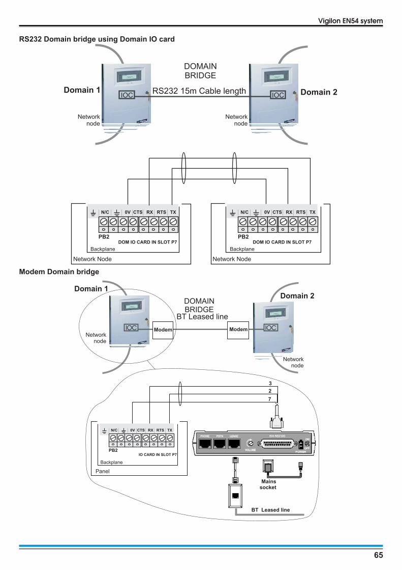
RS232 Domain bridge using Domain IO card
Modem Domain bridge
65
Vigilon EN54 system
DOMAINBRIDGE
IOCIOCDomain 1 Domain 2
Networknode
RS232 15m Cable length
Networknode
Network Node
Backplane Backplane
Network Node
PB2
N/C 0V CTS RX RTS TX
DOM IO CARD IN SLOT P7PB2
N/C 0V CTS RX RTS TX
DOM IO CARD IN SLOT P7
DOMAINBRIDGE
IOCIOC
Domain 1Domain 2
Networknode
BT Leased line
Networknode
Modem Modem
Panel
Backplane
3
2
7
Modem
25-wayD-type plug
BT Leased line
Mainssocket
PB2
N/C 0V CTS RX RTS TX
IO CARD IN SLOT P7

NPORT Domain bridge using NPORT module
� The customer is to supply the IP addresses.
66
Installation instructions
Networknode
Networknode
Dedicated Computernetwork
IOCIOC
Domain 1 Domain 2
RS232 15m maximum
NPORTDEVICE RJ45
GND
TxD
RxD
PSU PSU
NPORT CONVERTER UNIT NPORT CONVERTER UNIT
MAINS SUPPLY MAINS SUPPLY
NPORTDEVICERJ45
TxD
RxD
GND
DedicatedComputerNetwork
PATCH CABLES
NETWORK PORT
PARTS REQUIRED EN54 SETUP
2 x VIG-IO-DOM2 x VIG-DOM-NPORT
INFORMATION REQUIRED FROM CUSTOMER2 X IP NETWORK INFORMATION
2 X NETWORK PORTS
2 X PATCH CABLE
RxD GND TxD
NL
1
MAINS SUPLY
NPORT CONVERTER UNIT
NPORTCONV.UNIT
NPORTCONV.UNIT
PANEL
0V Tx Rx
DOMAIN IOCSET TO 19200
PANEL
0V Rx Tx
DOMAIN IOCSET TO 19200

Vigilon system partsThis section lists all the parts that can be used in a Vigilon EN54 system.For further details on the availability of the parts, contact your supplier.
Control PanelVIG1-24 EN54 Control panel (24 hour standby)
c/w 1 loop card and 2 x 12V 21Ah batteries
VIG1-72 EN54 Control panel (72hour standby) c/w 1-loop card,battery box and 4 x 12V 21Ah batteries
Spares
VS-BATT-24 Spare battery 2 x 12V 21Ahr for Control panel
VS-PROLL Spare thermal paper for the integral printer
VS-KEY Outer door key
Cards
VIG-LPC Loop Card (EN54)
VIG-MCC-24 Main Controller Card (EN54)(spare for VIG1-24 and VIG1-72)
VIG-NC Copper Network Card (EN54)
VIG-NC-FO Fibre Optics Network Card (EN54)
VIG-IOC-DOM Domain Bridge Input/Output Card (EN54)
AccessoriesVIG-24-FLUSH Flush mounting kit
(Control panels and Network node)
VIG-FLUSH-SS Stainless steel flush surround(Control panels and Network node)
VIG-DOOR-SS Stainless steel door
VIG-WR-CASE Control panel weather resistant case
VIG-19-RACK 19" Rack mounting frames for panel and battery box
Network NodeVIG-NODE-24 Network node
Repeat panelsVIG-RPT -72 Vigilon Repeat panel for EN/BS (loop connectable)
VSRPT-BATT Battery pack from Repeat panel
COMPACT-RPT Repeat indicator panel RS485(connects directly to the panel)
Mimic panelsVIG-MIM-A3 Zonal and Mimic panel (EN54)
VSRPT-BATT-A3 Battery back from A3 Mimic (2 x 6V 7Ah)
Manual call pointsS4-34800 Manual Call Point (Glass)
S4-34842 Manual Call Point (Glass) with Protective cover
S4-34845 Manual Call Point with resettable element
S4-34805 Manual Call Point with resettable elementand protective cover
S4-34890 Resettable Element for MCP (Pack of 10)
S4-34891 Glass for MCP (Pack of 10)
S4-34892 Protective cover for MCP (Pack of 10)
S4-34895 Surface Back Box for MCP red plastic - (Pack of 10)
S4-34898 Manual Call Point weather resistant kit
S4-34899 Test Key (Pack of 10)
S4-34895 Keyswitch call point (Red)
Keyswitch MCP
S4-34807 Keyswitch MCP (Red) with back box
S4-34499 Spare Keys (Pack of 2)
S4-34895 Surface Back Box for Interface Red Plastic (Pk of 10)
Environmentally protected enclosure for MCP
S4-34896 MCP Weatherproof box - S4-34805& S4-34800
S-Quad Sensors / Sounder / Strobe / SpeechS4-710 Optical Heat Sensor (OH)
S4-715 Optical Sensor (O)
S4-720 Heat Sensor (H)
S4-720-ST-VO Heat Sensor Strobe Speech (HStSp)
S4-780 Heat Sensor Sounder (HS)
S4-770 Optical Heat Sounder (OHS)
S4-711 Dual Optical Heat Sensor (O2H)
S4-711-ST Dual Optical Heat Sensor Strobe (O2HSt)
S4-771 Dual Optical Heat Sensor Sounder(O2HS)
S4-711-ST-VO Dual Optical Heat Sensor Speech Strobe (O2HSpSt)
S4-711-VO Dual Optical Heat Sensor Speech (O2HSp)
S4-911 Dual Optical Heat CO Sensor (O2HCO)
S4-911-ST-VO Dual Optical Heat CO Sensor Speech Strobe(O2HCOSpSt)
67
Vigilon EN54 System

Associated products
S4-700 S-Quad Base
13449-01 Remote LED for use with S4-700
S4-FLUSH Semi-Flush fixing kit
S4-COVER-DUST Sensor dust cover (50 pack)
S4-COVER-BASE Base dust cover (50 Pack)
S4-EXTRACTOR Removal tool
S4-BASE-LABEL Label plate (50 pack)
S4-BASE-GASKET Base IP Gasket (50 pack)
S4-COVER-REMOVER Dust cover remover tool (spare adaptor)
Environmentally protected sensor
34729 Environmentally protected Heat sensor
Duct SensorS4-34760 Venturi-Air Duct Kit
Beam SensorsS4-34740 Beam sensor pair
S4-34741-01 Angle bracket with base
S4-34741-03 Parallel bracket with base
S4-34741-99 Light shield for beams (5 per pack)
S4-34741-50 Test Cards
T Breaker34701 T breaker Unit
LV & MV Interfaces
Keyswitch Interface
S4-34418 Keyswitch Interface (Blue) with back box
S4-34499 Spare Keys (Pack of 2)
Low voltage interface range
S4-34410 1-Input Interface module (low voltage)
S4-34420 1-Output & 1-Input Interface module (low voltage)
S4-34450 4-Input / Output Interface module (low voltage)
Options
The above interface modules can be mounted in any of the followingoptional enclosure or DIN rail mount bracket.
S4-34490 Interface enclosure Large Plastic box
S4-34492 Interface enclosure Metal box
S4-34491 DIN rail mount bracket
S4-34493 Interface enclosure Small Plastic box
S4-34496 Interface enclosure houses 6 Interfaces
Medium voltage interface range
S4-34411 Single Output Interface Module DIN rail mountable(Medium Voltage)
S4-34415 Single Output Interface PCB with cover(Medium Voltage) in a metal box
12 input interface
S4-34412 12 input interface module (Supervisory inputs only)
S4-34494 Connection Converter for S4-34412
Mains powered interfaces (from Qtr 3 2010)S4-34440-02 Mains powered fire alarm interface 24V only
S4-34440-12 Mains powered fire alarm interface 12V / 24V
19104-52 Low voltage power relay
17740-20 Intrinsically safe galvanic isolator for
IS detectors and call points
02518-10 Intrinsically safe galvanic isolator for
IS sounders
68
Installation instructions

S3
Addressable Speech, Sounder Strobe
Strobe
Low profile range
Body Strobe - Deep base
White S2IP-ST-WR (red lens) S2IP-ST-WA (amber lens)
Red S2IP-ST-RR (red lens) S2IP-ST-RW (white lens)
Sounder Strobe
Low profile range
Sounder Sounder Strobe (red lens)
Body Deep base Shallow base Deep base Shallow base
White S3IP-SN-W S3-SN-W S3IP-SN-ST-WR S3-SN-ST-WR
Red S3IP-SN-R S3-SN-R S3IP-SN-ST-RR S3-SN-ST-RR
Low profile variants
Sounder Strobe
The S2IP-SN-R3 and S2IP-SN-W3products are suitable for retrofittingand are supplied with a 6-wayterminal block to ease cableconnection.
Red S3IP-SN-ST-RW (white lens)
White S3IP-SN-ST-WA (amber lens)
System range
Sounder
Red S2IP-SN-R(2-way)
S2IP-SN-R3(3-way)
White S2IP-SN-W(2-way)
S2IP-SN-W3(3-way)
Note: The system range of products do not support strobe options.
Speech Sounder Strobe
Low profile range
Speech Sounder Speech Sounder Strobe (red lens)
Deep base Shallow base Deep base Shallow base
White S3IP-VP-W S3-VP-W S3IP-VP-ST-WR S3-VP-ST-WR
Red S3IP-VP-R S3-VP-R S3IP-VP-ST-RR S3-VP-ST-RR
Remote Control
S3-CONTROL Remote control for the S3
69
Vigilon EN54 system

Domain Bridge productsVIG-NPORT-100 NPORT IP Domain module 100M
(single unit)
VIG-DOM-MODEM Modem pair
Surge protection5530440 1 x Mains, 1 x Loop & 1 x Zone/Sector suppression
(enclosure has space for 1 extra loop (2 x 2817958)
5530452 1 x Mains, 1 x Network, 1 x Loop & Zone / Sectorsuppression (enclosure has space for 1 extra loop(2 x 2817958)
5530465 1 x Mains, 1 x Network suppression
5530478 1 x Mains suppressor
2817958 1 x Additional Loop suppressor (module only)
Replacement Plug ins
2798844 Mains suppressor
2838762 Network suppressor
2839648 Loop suppressor
2838351 Zone / Sector suppressor
Manuals4188-774 EN54 Vigilon 4/6 loop panel based system
Operating instructions
4188-749 Log book
Supported products
Sensors (Supported)
34710 Optical heat sensor
34710-RL Optical heat sensor for remote LED connection
13449-01 Remote LED
34770 Optical heat sensor sounder
34780 Heat sounder
34720 Heat sensor
34760 Duct sensor (inc 17908-05 Probes &34702 Slave LED unit)
Spares
19271-01 Replacement Optical chamber
Terminal Plate
34700 3-way terminal plate
34704 4-way terminal plate
19279-01 Semi-flush sensor mounting kit
19270-50 Sensor dust cover (50 pack)
Tools
17918-26 Sensor removal tool kit
Manual call points (Supported)
34800-EN Surface mounted MCP
34807 Surface mounted keyswitch MCP
19289-01 MCP flush fixing plate
34829-EN Environmentally protected surface mounted MCP
14112-09EN Spare MCP glasses 10 pack non LPCB approved
14112-49EN Hinged cover with drilled from moulding
14112-EN-KIT BS to EN Front conversion kit with glass
Interfaces (Supported)
34415 Single Channel loop powered interface
19245-05 Interface line module
70
Installation instructions

Notes
71
Vigilon EN54 system

Gent by Honeywell reserves the right to revise this publication from time to time and make changes to the content hereof without obligation to notifyany person of such revisions of changes.
Hamilton Industrial Park, Waterside Road, Leicester LE5 1TN Website: www.gent.co.uk
Telephone: +44 (0)116 246 2000 Fax (UK): +44 (0)116 246 2300
Technical Support: www.gentexpert.co.uk
72 4188-875 issue 5_07/10_Vigilon 4-6L EN54_Install
Installation instructions
0832
Gent by HoneywellHamilton Industrial Park, 140 Waterside Road, Leicester LE5 1TN, UK
0832-CPD-1261 1-4 LOOP (VIG1-24 -PO/NP/SP)
Control and Indicating equipment for fire detection and fire alarm systemsin buildings.
0832-CPD-1262 1-6 LOOP (VIG1-72 -PO/SP)
7.8 Output to fire alarm devices7.11 Delays to action outputs8.3 Fault signals from point9.5 Disablement of each addressable point10 Test condition
Power supply equipment for fire detection and fire alarm systems inbuildings.
Other technical data: see documents in project file 7023, held by themanufacturer.
Vigilon
EN54-2: 1997, A1:2006
EN54-4: 1997, A1:2002, A2:2006
At the end of their useful life, the packaging,product and batteries should be disposed ofvia a suitable recycling centre and inaccordance with national or local legislation.
Do not dispose of with your normal household waste.Do not burn.
WEEE Directive:At the end of their useful life, the packaging,product and batteries should bedisposed of via a suitable recycling centre.
by Honeywell