Embed Size (px)
Citation preview

DESCRIPTION FEATURES
EN
5.23
1.5.
0/0
1.20
1
High flow capacity due to optimized, cast casing Low hysteresis due to precision machining of moving parts The pilot supply or pilot drain can be internal or external The control results directly from the integrated Onboard electronic Easy interchangeability due to internationally standardised interface
according to ISO 4401
The P4WEHRE is a pilot operated proportional directional valve with integrated electronic and transducer, which combines directional control with speed control of the consumer.
The controlled volume flow is proportional to the electrical input signal on valve electronics.
According to the input signal, the magnet generates a control pressure, which shifts hydraulically the main piston against a spring. In this process, cross-sections are released, which determine the size of the volume flow depending on the pressure difference.
The integrated digital electronics in combination with the transducer allows improved performance and function due to
- regulation of size and direction of a volume flow
- short response times
- low hysteresis
- high repeatability
4/3 proportional directional valveshydraulic pilot operated with OnboardElectronic and transducerP4WEHRE 10 to 25
CONTENTDescription FeaturesModel codeSpool types / SymbolsTechnical Data FunctionSection viewAccessoriesPerformanceDimensionsElectronic
1 123344457
10
MODEL CODE
EN
5.23
1.5.
0/0
1.20
2
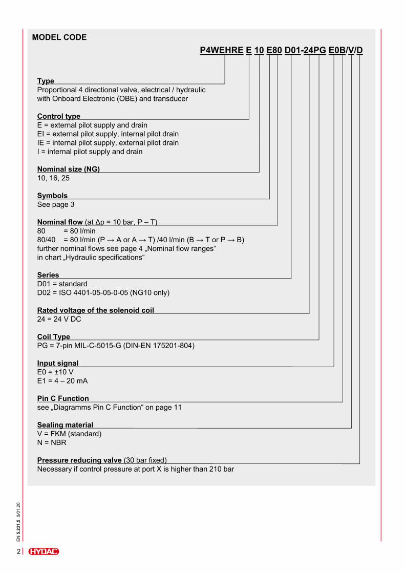
P4WEHRE E 10 E80 D01-24PG E0B/V/D
TypeProportional 4 directional valve, electrical / hydraulicwith Onboard Electronic (OBE) and transducer
Control typeE = external pilot supply and drain EI = external pilot supply, internal pilot drain IE = internal pilot supply, external pilot drain I = internal pilot supply and drain
Nominal size (NG)10, 16, 25
SymbolsSee page 3
Nominal flow (at Δp = 10 bar, P – T)80 = 80 l/min80/40 = 80 l/min (P → A or A → T) /40 l/min (B → T or P → B)further nominal flows see page 4 „Nominal flow ranges“ in chart „Hydraulic specifications“
SeriesD01 = standardD02 = ISO 4401-05-05-0-05 (NG10 only)
Rated voltage of the solenoid coil24 = 24 V DC
Coil TypePG = 7-pin MIL-C-5015-G (DIN-EN 175201-804)
Input signalE0 = ±10 VE1 = 4 – 20 mA
Pin C Functionsee „Diagramms Pin C Function“ on page 11
Sealing materialV = FKM (standard)N = NBR
Pressure reducing valve (30 bar fixed)Necessary if control pressure at port X is higher than 210 bar

EN
5.23
1.5.
0/0
1.20
3
Switching time (0 → 100%):Switching time (100% → 0):Type of voltage: Rated voltage:Hysteresis:Repeatability:Protection class to DIN EN 60529:
According to EN ISO 13849-1:2015 chart C1 & C2 -20 to +60No orientation restictions
Valve casing: Cast ironName plate: AluminiumValve casing: Phosphate
[ms][ms]
[V][%][%]
DC12, 24< 0,5 of Qmax
< ±0,2 of Qmax
with electrical connection “G“ IP65 ²
Port P: pmax = 350Port T, internal leak port: pmax = 10Port T, external leak port: pmax = 250pmin = 30pmax = 210
Hydraulic oil to DIN 51524 part 1, 2 and 3-20 to +80 10 – 400 class 18/16/13 to ISO 4406
NBR, FKM (standard)
TECHNICAL DATA ¹General specifications
MTTFd:Ambient temperature: Installation position:Weight:Material:
Surface coating:
Hydraulic specifications
Operating pressure:
Control pressure:
Max. nominal flow:Nominal flow ranges:(at Δp = 10 bar, P → T)
Operating fluid:Media operating temperature range: Viscosity range:Permitted contamination levelof operating fluid:Sealing material: Control flow:(Control 0 → 100 %)Control volume:(Control 0 → 100 %)
[°C]
[kg]
[bar]
[bar]
[l/min][l/min]
[°C][mm²/s]
[l/min]
[cm³]
Electrical specifications
¹ see „Conditions and Instructions for Valves“ in brochure 53.000² if installed correctly
HintIf the system pressure exceeds the max. allowable control pressure, it is necessary to use the version with external control andcontrol pressure within the specifications. Otherwise, the valve with internal pilot control and pressure reducing valve as 30 bar fixed sandwich plate can be ordered.
Nominal size10
9,0
16
11,0
25
17,5
Nominal size10
18080
80/40
3,5
1,7
16
450100150
150/75
6,4
3,2
25
800200300
300/150
15,3
9,2
Nominal size105040
165040
256040
4/2-DIRECTIONAL SPOOL VALVES 4/3-DIRECTIONAL SPOOL VALVES
Type Basic model Type Basic model
EA E
JA J
KOLBENTYPEN / SYMBOLE

FUNCTION SECTION VIEW
DesignationP4WEHRE 10: 12,42 x 1,78 90 Sh (5 pcs) FKM: 3524523
9,25 x 1,78 90 Sh (2 pcs) NBR: 3524475P4WEHRE 16: 22,22 x 2,62 90 Sh (4 pcs) FKM: 3524634
10,82 x 1,78 90 Sh (2 pcs) NBR: 3524553P4WEHRE 25: 29,82 x 2,62 90 Sh (4 pcs) FKM: 3524660
20,24 x 2,62 90 Sh (2 pcs) NBR: 3524659P4WEHRE 10: ISO 4762 M6 x 35 (4 pcs) 604593P4WEHRE 16: ISO 4762 M10 x 60 (4 pcs) 4501973
ISO 4762 M6 x 60 (2 pcs) 4501973P4WEHRE 25: ISO 4762 M12 x 60 (6 pcs) 619501
Main Connector 6+PE EN175201 Part 804 6080324Electronic Lin-Bus Interface 3648934
EN
5.23
1.5.
0/0
1.20
4
The P4WEHRE is a hydraulic pilot operated, proportional 4 directional valve with integrated OBE and transducer. The volume flow is controlled continuously (proportionally) to the electrical input signal at the solenoid coil. These valves essentially consist of the pilot stage (pressure regulating valve) and the main stage (directional valve). The pilot stage consists of the valve housing (1), a control piston with 2 pressure measuring pins (2) and two proportional solenoids (3). The proportional solenoid coils are controlled via the integrated Onboard electronic (7). OBE and pilot stage are connected via the main connector (8). The main stage consists of the housing (4), a main piston (5) and a centringspring (6) acting in both directions.
The transducer (9) in the main stagemonitors the position of the mainpiston. The pressure supply of the valve results from the interface according to ISO 4401. The external pilot supply and drain result from port X and Y to the pilot valve. The regulated control pressure is proportional to the stroke of the main stage. If one of the two solenoids is energized, the pilot releases the connection to control port A or B and regulates the control pressure according to the set solenoid current.
The main piston shifts until a balance offorce is reached by pressurizing one ofthe two sides of the main piston via control pressure. The desired connection PABT or PBAT is released.The transducer makes an target-performance comparison of the main piston position and corrects differences via OBE.
If the valve is subsequently relieved of pressure, the centring spring returns the main piston to neutral again.
P4WEHRE valves are available in different versions, which differ in their interface. Due to this difference, the valve versions are not compatible with each other.
ACCESSORIESPart no.
Seal kits (main stage)
Mounting screws
3
2
1
4
3
5
6
7
8

PERFORMANCE
The performance represent typical curves for the various available valve pistons, at a constant Δp, depending on the current supplied by the solenoid coil. (Note: The maximum current for the solenoid version D24 is 800 mA).The total valve pressure drop (Δp) was measured between port P and T of the valve.
Q-I-Performance NG10 (measured at 36 cSt, 50°C), symbols E; EA; EB; J; JA; JB, nominal flow 80 l/min
Q-I-Performance NG16 (measured at 36 cSt, 50°C), symbols E; EA; EB; J; JA; JB, nominal flow 100 l/min
Nominal flow 150 l/min
Q-I-Performance NG25 (measured at 36 cSt, 50°C), symbols E; EA; EB; J; JA; JB, nominal flow 200 l/min
Nominal flow 300 l/min
EN
5.23
1.5.
0/0
1.20
5
Control signal [%]
Control signal [%]
Control signal [%]Control signal [%]
Control signal [%]

PERFORMANCE
Switching time (measured at 36 cSt, 50°C), symbolsE, EA, EB, J, JA
NG10
NG16
NG25
Plug
Control type Installation
X Y
E external pilot supply and drain ● ●
EI external pilot supply, internal pilot drain ● -
IE internal pilot supply, external pilot drain - ●
I internal pilot supply and drain - -
• Version „E“ Pilot oil supply is external from a separate fluid power supply via port X. The pilot oil drain is also external via port Y.
• Version „EI“Pilot oil supply is external from a separate fluid power supply via port X. The pilot oil drain is internal via port T.
• Version „IE“ Pilot oil supply is internal via port P. The pilot oil drain is external via port Y.
• Version „I“ Pilot oil supply is internal via port P. The pilot oil drain is internal via port T.
The valve is configured and delivered as required. The threaded plugs are glued in at delivery.Subsequent modification is not possible.
EN
5.23
1.5.
0/0
1.20
6
Con
trol
sig
nal[
%]
Con
trol
sig
nal[
%]
Con
trol
sig
nal[
%]

INTERFACECETOP 4.2-4 P05-350 (D01)
INTERFACEISO 4401-05-05-0-05 (D02)(CETOP 4.2-4 R05-350)
Mounting screws (ISO 4762): 4 pcs M6 x 35 A8.8 (not included in delivery)Torque: 8 Nm
HintWhen using the pressure reducing as sandwich plate, the installation height changes by 40 mm to 250 mm.
DIMENSIONS NG10
standardmanual override
EN
5.23
1.5.
0/0
1.20
7

DIMENSIONS NG16
INTERFACEISO 4401-07-07-0-05 (D01)(CETOP 4.2-4-07-350)
Mounting screws (ISO4762): 4 pcs M10x60 A8.8 (not included in delivery)2 pcs M6 x 60 A8.8 (not included in delivery)
Torque: M10: 40 NmM6: 8 Nm
HintWhen using the pressure reducing as sandwich plate, the installation height changes by 40 mm to 260 mm.
standardmanual override
EN
5.23
1.5.
0/0
1.20
8
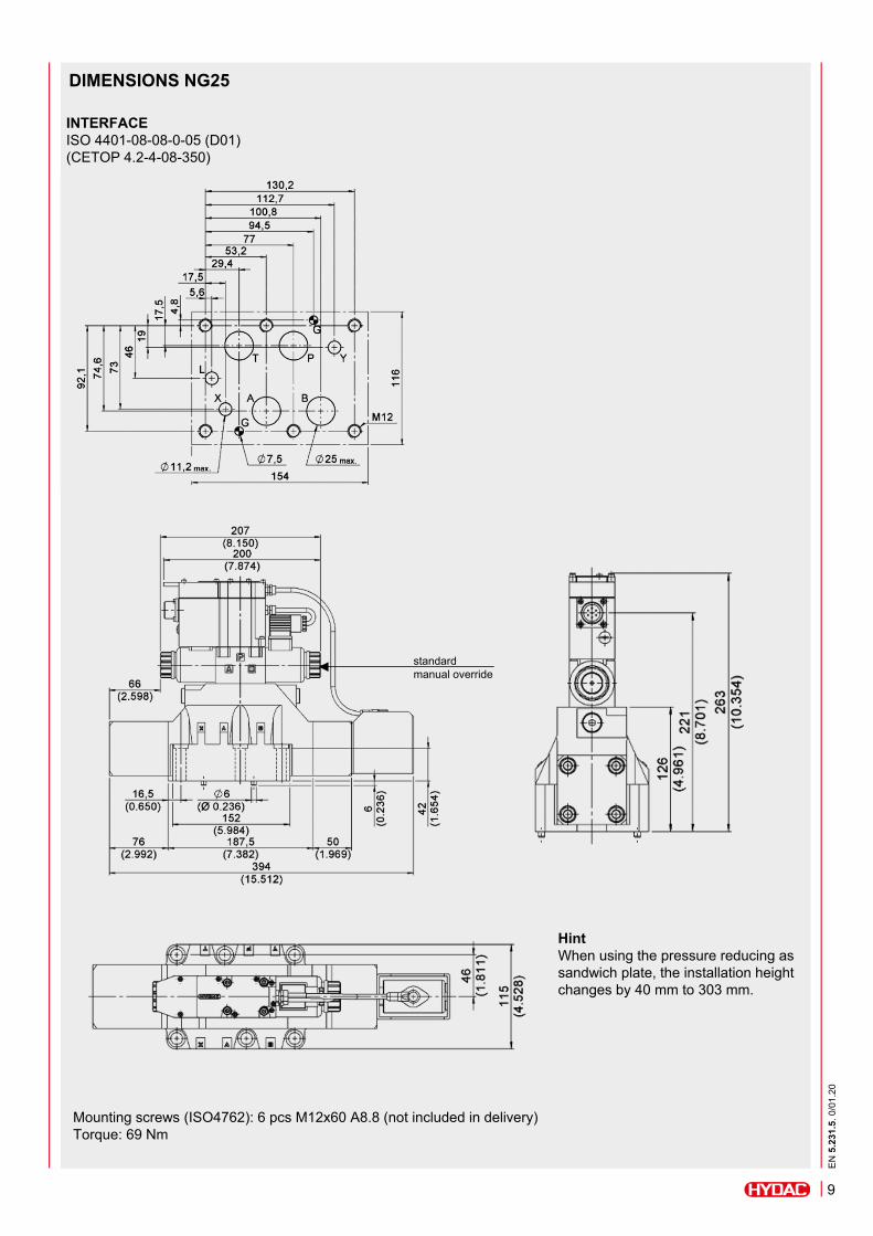
DIMENSIONS NG25
INTERFACEISO 4401-08-08-0-05 (D01)(CETOP 4.2-4-08-350)
Mounting screws (ISO4762): 6 pcs M12x60 A8.8 (not included in delivery)Torque: 69 Nm
HintWhen using the pressure reducing as sandwich plate, the installation height changes by 40 mm to 303 mm.
standardmanual override
EN
5.23
1.5.
0/0
1.20
9

INTEGRATED ELECTRONIC
General specifications
Power consumption: 25 W
Current consumption: max. 1,88 A
Rated voltage: 24 V DC (19 – 30 V DC, ripple max. 3 Vpp)
Duty cycle: 100% ED (continuous)
Control signal E0: Voltage signal ±10 VDC
Control signal E1: Current signal 4 – 20 mA
Alert signale: Overload and overheating of electronics
Communication: LIN-Bus ISO 11898 LIN-Bus Interface
Electronical connection: 7-pin MIL-C-5015-G (DIN-EN 175201-804)
LIN-Bus connection: M12-IEC 60947-5-2
EMC EN61000-6-4: According to 2014/30/EU standard
EMC EN61000-6-2: According to 2014/30/EU standard
Type of protection: IP65 / IP67 (CEI EN 60529 standard)
Parameterisable only via LIN bus
1) Valve with proportional solenoids2) Valve piston3) Proportional solenoid4) Main connector 5) Electronic housing
EN
5.23
1.5.
0/0
1.20
10
3
2
1
3
7
8
5
4

ELECTRONIC
Standard version with reference signal voltage E0 Diagramms PIN C Function
Version A: External release (on request)
Version B: Internal release (standard)
Standard version with reference signal current E1
Version C: 0V Monitor (on request)
Hint 1- Voltage signal (0V centring position)
• -10V to 0 V: flow direction P – B and A – T • 0V to +10V: flow direction P – A und B – T
- Current signal (12 mA centring position)• 4 mA to 12 mA: flow direction P – B and A – T • 12 mA to 20 mA: flow direction P – A and B – T
- With one solenoid (type EA and JA)• 4 mA to 20 mA: flow direction P – B and A – T • 0V to +10V: flow direction P – B and A – T
Pin D and Pin E must always be contacted.
Hint 2PIN C function A and B: Nominal input value measured between pin F and pin B.
Hint 3We recommend to provide an external protection at pin A (24 V DC) for protection of the electronics: 5A/50V fast fuse.
PIN Value Version A Version B Version C
A 24 V DCSupply voltage
B 0 V
Crelease24 V DC
unoccupiedPIN F
reference0 V
D +/- 10 V control (differential input)
E 0 V PIN D reference
F +/- 10 Vmonitor
(0V reference PIN B)monitor
PE GND earth (mass)
PIN Value Version A Version B Version C
A 24 V DCSupply voltage
B 0 V
Crelease
24 V DC
unoccupiedPIN F
reference0 V
D4 - 20 mA
control
E 0 V PIN D reference
F4 - 20 mA
monitor (feedback)(0V reference PIN B)
monitor(feedback)
PE GND earth (mass)
EN
5.23
1.5.
0/0
1.20
11

LIN-BUS INTERFACE
HintWe recommend the use of a metal connector to ensure electromagnetic compatibility (EMC) and to avoid electromagnetic disturbances.
1) LED2) USB Micro B socket
(cable with – length = 2 m -in delivery)
3) Main connector with 7 Pin
In the casing of electronics, a 7-pole port for connecting with external devices is integrated.
The cable diameter for the main connector (cable and connector are not included in delivery) has to be min. 8 mm and should be max. 10 mm.
Is also required for parameterisation of Onboard electronic.
• The kit contains a test device with embedded connection cable 7 pin and a USB cable for connection to the PC. The dedicated software are available for download from our website.
• The device is suitable for troubleshooting and functional testing of HYDAC proportional valves with LIN-bus interface.
• The software allow the check of settings, display the diagnostic and permit to make changes on the standard parameter setting made in factory, adapting it to your system.
• No additional power supply is required: the device uses the supply source from the 7 PIN system cable.Content*: Parameterize-software, adapter and
PC connection cable
* On request (not included in delivery)
NoteThe information in this brochure relates to the operating conditions and applications described. For applications not described, please contact the relevant technical department. All technical details are subject to change without notice.
HYDAC Fluidtechnik GmbHJustus-von-Liebig-Str.D-66280 Sulzbach/SaarTel: 0 68 97 /509-01Fax: 0 68 97 /509-598E-Mail: [email protected]
N5.
231.
5. 0
/01.
20
12
up to the valve
cable = 2 m
up to the system


![Presentación de PowerPointPTPS [m/s] 60 40 20 0 -20 -40 June 25 60 40 20 0 -20 -40 June 25 60 40 20 0 -20 -40 June 25 60 40 20 0 -20 -40 June 25 FIB B RV drift FIB B RV drift LN2](https://img.dokumen.tips/doc/110x75/5e3aa885f6b91639da1e26a2/presentacin-de-powerpoint-ptps-ms-60-40-20-0-20-40-june-25-60-40-20-0-20.jpg)