Embed Size (px)
Citation preview
EN - Instructions and warnings for installation and use
Automation for sectional and rolling door
Pro-LHA

NICE CANADA warrants that materials and workmanship are free from defects for a period of two years from the date of invoice. Materials returned to Nice deemed defective after examination will be returned at the option of Nice with repaired, new or re-manufactured parts.
NICE CANADA will not be responsible for any extra charges incurred in the process of returning defective material. All returned material must be received pre-paid or it will not be accepted.
This warranty is limited, and in lieu of all other warranties expressed or implied. There is no expressed liability due on the part of the seller.

2
TABLE OF CONTENTS PAGE:
3
4
5
6
9
19
20
24
24
25
26
27
29
WARRANTY _________________________________________________________________
VERIFICATION OF OPERATOR AND HARDWARE ___________________________
SPECIFICATIONS ___________________________________________________________
SAFETY INSTRUCTIONS ____________________________________________________
INSTALLATION_______________________________________________________________
ELECTRICAL CONNECTIONS AND SETTINGS________________________________
LIMIT SWITCH ADJUSTMENT _______________________________________________
PHOTOBEAM INSTALLATION INSTRUCTIONS________________________________
CLUTCH ADJUSTMENT______________________________________________________
BRAKE ADJUSTMENT_______________________________________________________
EMERGENCY MANUAL OPERATION _________________________________________
OPERATOR MAINTENANCE _________________________________________________
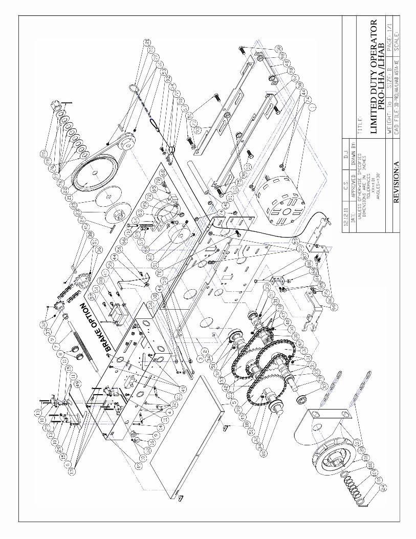
MECHANICAL DRAWINGS AND PARTS LISTS ________________________________
ELECTRICAL DIAGRAMS ___________________________________________________
1
WARNING
DO NOT CONNECT TO ELECTRICAL POWER DURING INSTALLATION OR
SERVICING OF OPERATOR

3
IMPORTANT FOR ANY QUESTIONS CONCERNING THE SAFETY OR OPERATION OF THIS OPERATOR
PLEASE CONTACT NICE AT 1-877-888-1116 SAVE THESE INSTRUCTIONS
VERIFICATION OF OPERA TOR AND HARDWARE
Upon delivery of your Nice medium-duty jackshaft for rolling door operator, please inspect the unit carefully for damage. Verity that operator horsepower, voltage, phase and amperage correspond to available power supply and door application. Check that along with your operator you have received the following standard hardware.
1 x OPEN/CLOSE/STOP 3-button control station:
1 x #41 Drive chain package : 5' (1.2m) c/w #41 connecting link
1 x Drive Sprocket 41 B 14 x l" c/w 2 set screws and ¼" x 1-1/4" keyway
x Door Sprocket 41B32 x l" c/w 2 set screws and¼" x 1-1/4" keyway Note: Sprocket size and bore may vary according to door size and type, shaft size and drum diameter
1 x Chain keeper
1 x Keyring
���
4 x 3/8" bolt, hex nut, lock washer and flat washer ��������1 x pocket wheel hand chain (2 x door height less 4' (1.2m))
�� ��������
1 x Warning sign
1 set of Nice photocells (supplied when operator ordered with interface module or logic board controls)

4
PRO-LHA SPECIFICATIONS
PRO-LHA medium duty jackshaft operators are designed for commercial sheet doors and rolling doors provided that these doors are driven by a drive shaft with low duty cycles. Model PRO-LHA operator incorporates a chain hoist for manual operation of the door. Model PRO-LHAB has additional solenoid brake system.
STANDARD OPERATOR WEIGHT: 45-50 LBS
MOTOR: Intermittent duty 1000 RPM motor with high starting torque. - Thermally protected by a built-in thermostat that cuts power to the motor and control circuit when overheating.- Horsepower: l/2HP - Voltage: 115V I-phase (60Hz)
230V I-phase (60Hz) 220V I-phase (50Hz) 380V 3-phase (50Hz)
IMPORTANT NOTE THIS MEDIUM DUTY OPERA TOR IS DESIGNED TO OPERA TE
A MAXIMUM OF 15 COMPLETE CYCLES PER HOUR.
TRANSFORMER: 24VAC control circuit, supplies power to drive control relays with 15V A power available for external devices.
LIMIT ADJUSTMENT: 4 micro switches that control door travel. These limit switches are activated by fully adjustable screw type cams.
EMERGENCY DISCONNECT: Floor level cable disconnect system with electrical cut-out feature allows person to manually operate the door by chain hoist in case of emergency.
CLUTCH: Adjustable friction clutch to minimize damage to door operator, door or vehicles when obstruction occurs.
OPERATOR DIMENSIONS:
15-1/2' __ _, WALLMOUNT BRACKET MOUNT
n n n n n
14-1/4'
n n
8-1/16' >----+-4-3/4'
REDUCTION: P : 4L V- pulleys 1 5 .. 7 S : 41
OUTPUT SHAFT SPEED: 39 RPM
BRAKE : Mechanical brake system to prevent coasting and maintain door position.
SOLENOID BRAKE (OPTIONAL): Solenoid brake system available for model PRO-LHAB
WIRING TYPE 3 OPTIONS : O 1: L D S 5 0 UL325 2010 N : Nice
B2 TS O 2: R I M UL325 2010 C2 S
I B2 5 N : Nice
B2 O 3: S UL325 2010 US C-2 W
close, momentary contact on open and stop. NOTE: If momentary contact on close (B2) wiring is desired, connect 5

5
IMPORTANT SAFETY INSTRUCTIONS
�WARNING
TO REDUCE THE RISK OF INJURY OR DEATH:
READ AND FOLLOW ALL INSTRUCTIONS
Never allow children to operate or play with door controls. Keep the remote control (where provided) away from children.
Personnel should keep away from a door in motion and keep the moving door in sight until it is completely closed or opened. NO ONE SHOULD CROSS THE PATH OF A MOVING DOOR.
Test the door's safety features at least once a month. After adjusting the limit of travel, retest the door operator's safety features. Failure to adjust the operator properly may cause severe injury or death.
For products having a manual release, if possible, use the manual release only when the door is closed. Use caution when using this release when the door is open. Weak or broken springs may cause the door to fall rapidly, causing severe injury or death.
KEEP DOORS PROPERLY OPERATING AND BALANCED. See Door Manufacturer's Owner's Manual. An improperly operating or balanced door could cause severe injury or death. Have trained door systems technician make repairs to cables, spring assemblies, and other hardware.
Press the "OPEN" device or use emergency disconnect mechanism if a person is trapped under the door.
SA VE THESE INSTRUCTIONS. The owner or users must understand the safety and operation of door system. Insure that this installation manual be located close to the door system.
IMPORTANT INSTALLATION INSTRUCTIONS
READ AND FOLLOW ALL INSTALLATION INSTRUCTIONS
Commercial door operators are never to be installed on a residential installation
Install only on a properly operating and balanced door. A door that is operating improperly could cause severe injury. Have qualified service personnel make repairs to cables, spring assemblies, and other hardware before installing the operator.
Remove all pull ropes and remove, or make inoperative, all locks (unless mechanically and/or electrically interlocked to the power unit) that are connected to the door before installing the operator.
Install the door operator at least 8 feet or more above the floor if the operator has exposed moving parts.
Do not connect the operator to the source of power until instructed to do so.
Locate the control station: ( a) within sight of the door, (b) at a minimum height of 5 feet so that small children cannot reach it, and ( c) away from all moving parts of the door.
Install the Entrapment Warning Placard next to the control station in a prominent location.
For products having a manual release, instruct the end user on the operation of the manual release.
Install non-contact entrapment protection devices (photocells) and/or contact entrapment protection devices (reversing edges). Note: photocells should be installed at no more than 6" from the floor. Edges should be installed on the leading edge of the door.

6
INSTALLATION INSTRUCTIONS
� WARNING DO NOT INSTALL THIS OPERATOR
BEFORE READING THIS MANUAL CAREFULLY.
Note: � Installation of operator must be done by a qualified installer. Door must be properly installed and working smoothly. Remove all door locks prior to installation.
� The PRO-LHA operators have dual output shafts and may be mounted on left (standard) or right hand side of door. If handing of operator must be reversed, loosen set screws, remove drive sprocket and keyway and install on opposite side of drive shaft.
LEFT HAND RIGHT HAND
- For the PRO-LHA operator which incorporates a chain hoist mechanism the handing of the operator must bestated at time of order. Depending on installation, if handing of chain hoist is not correct the hand chain mayhang in door opening. If this is the case, swing chain off to the side and hook it over the top of the door jamb. Donot attempt to reverse chain hoist on site.
1. Install control station away from all moving door parts, within sight of the door and a minimum of 5 ft (1.5 m)from the ground.
2. Install entrapment warning sign next to control station.

7 3. As a general rule, the door operator should be installed below the drive shaft and as close to the door as possible.The ideal distance between the operator drive shaft and the door shaft is approximately 12” (30cm) to 15” (38cm).
The operator may be wall/bench mounted or bracket /shelf mounted. These two mounting configurations are shown below:
4. Mount the operator to the wall, hood or bench with 3/8” bolts, nuts and washers provided or with lag boltsand shields if installation requires it. Make sure that operator is secured but do not tighten bolts.
5. Place door sprocket on door shaft and align with operator drive sprocket but do not insert keyway or setscrews.
6. If an optional chain spreader has been ordered with your operator, install as shown below:
7. Install drive chain over sprockets, cut to a suitable length and connect with connecting link.
8. Lower or raise operator to adjust chain tension so that there is no more than ¼” chain slack betweensprockets. Tighten operator mounting bolts.
9. Carefully re-align sprockets, if necessary and secure keyway and set screws.
10. Install hand chain by wrapping it through chain guard holes and pocket wheel. Allow chain to hang downtowards floor. Cut chain and connect so that chain is 2’ to 3’ from the floor.

8 11. Install chain keeper to wall near hand chain at approximately 4’ from floor. Run disconnect chain through keyhole of
chain keeper and cut excess chain links if required. Attach keyring to end of disconnect chain.
12. If an optional floor level disconnect lever was ordered in lieu of the chain keeper, mount to wall with suitablehardware. Attach both chains together using keyring provided. Allow disconnect chain to be slightly slackwhen lever is in the up position.

9
THERE ARE 3 POSSIBLE ELECTRICAL CONTROL CONFIGURATIONS FOR THIS OPERATOR:
A) Standard relay logic controls (not UL325 (2010) compliant, not available in US). Refer to Section A forelectrical connections. Refer to electrical drawings inside your operator control box or generic drawingsMSLHA-WW, MSLHA2-WW or MS300LH-WW in the electrical drawings section at the end of this manual.
B) Relay logic controls with Interface Module (UL325 (2010) compliant. Refer to Section B for electricalconnections. Refer to electrical drawings inside your operator control box or generic drawings MSLHA-IM-WW or MSLHA2-IM-WW or MS300LH-IM-WW in the electrical drawings section at the end of this manual.
C) Limited duty logic board Smart 5.0 (UL325 (2010) compliant). Refer to Section C for electricalConnections and logic board instructions. Refer to electrical drawings inside your operator control box orgeneric drawings MSLLHR-WW or MSLLHR220-WW, in the electrical drawings section at the end of thismanual.
Refer to electrical diagrams inside control box cover or at the end of this manual prior to connection of power supply or control station.
WARNING
TO REDUCE THE RISK OF INJURY OR DEATH:
ALL ELECTRICAL CONNECTIONS SHOULD BE MADE BY A QUALIFIED SERVICE PERSON
DO NOT ATTEMPT TO MAKE ELECTRICAL CONNECTIONS TO OPERATOR UNLESS POWER SUPPLY HAS BEEN DISCONNECTED AT FUSE BOX
OPERATOR MUST BE CONNECTED IN ACCORDANCE TO LOCAL ELECTRICAL CODES AND GROUNDED TO GREEN GROUND LUG LOCATED INSIDE CONTROL BOX
WARNING
COMPARE AVAILABLE POWER SUPPLY VOLTAGE TO OPERATOR NAMEPLATE PRIOR TO ELECTRICAL CONNECTION. FAILURE TO CONNECT APPROPRIATE POWER SUPPLY
VOLTAGE MAY CAUSE SERIOUS DAMAGE TO OPERATOR.
ELECTRICAL CONNECTIONS
IMPORTANT
- NICE HIGHLY RECOMMENDS THAT EACH INDIVIDUAL COMMERCIAL DOOR OPERATOR HAVE IT’S OWN DEDICATED POWER SUPPLY
- NICE HIGHLY RECOMMENDS THAT EACH INDIVIDUAL COMMERCIAL DOOR OPERATOR HAVE AN EXTERNAL CIRCUIT BREAKER OR FUSED DISCONNECT

10
SECTION A: PRO-LHA Standard relay logic controls (not UL325 (2010) compliant, not available in US)
CONNECTION OF POWER SUPPLY AND CONTROL STATION
POWER WIRING: Use 1-1/8" (2.85 cm) diameter holes for all power wiring.
1. Single phase: Connect single phase power supply to terminals L/Ll (line) and N/L2 on three-polepower terminal strip.
2. Three-phase (for l/2HP 380V 50Hz): Connect three phase power supply to terminals Ll, L2 and L3 on three-polepower terminal strip.
��������
�� ��
���� ���
�������
����� �� �� �� �
�� �� ��
CONTROL WIRING: Use 7/8" (2.22 cm) diameter holes for all control wiring. Note: Do not run control wires and power wires in same conduit.
�� ���� �� � ��� �� ���� ��
- Install control station within clear sight of door but away from all moving parts of door or hardware.Install Entrapment warning sign next to control station. Connect 3-button (open/close/stop) pushbutton station to terminals 2, 3, 4 and 5. Refer to electrical diagram for connection of two 3-button stations.
NOTE: After electrical connections are made, manually move door to mid-position and, using the control station press the "Open" button for several seconds and then press the "Stop" button. If door did not move in correct direction verity wiring control station. For 3-phase (380V 50Hz) operators, if door still moves in wrong direction reverse any two of the three incoming power supply leads to correct rotation.
3-PHASE
������ ��� ��� ��� ��
LIMIT SWITCH ADJUSTMENT
- Adjust Limit switches as explained in the "Limit switch adjustment section" further in this manual.

11
CONNECTION OF A REVERSING EDGE DEVICE AND CONTROL ACCESSORIES
1. Reversing Edge device (must be normally open contact):Note: If the door is controlled by any device or wired in such a manner that the door is not controlled by constant pressure on close then an appropriate reversing edge must be installed.
2. External interlock: Remove jumper between terminals 1 and 2 and wire a N.C. interlock contact between these twoterminals.
��
3. Radio control receiver: Wire standard radio receiver to separate radio strip on side of control box or to terminals 7, 8 and 9on control terminal strip inside control box.
����� �� ������
����������
4. Single button open/close device: Wire to terminals 7 and 8 on control terminal strip.
5. Loop detectors, standard photocells (with a N.O. contact) and other reversing devices: Wire to terminals 3 and 6 oncontrol terminal strip.
6. 24 Volt power: Wire to terminals 1 and 9 on control terminal strip
�� ��� �������� � ���
�� �� �� �� �� �� �� ����������
��

12
SECTION B: PRO-LHA(M) Relay logic controls with Interface Module (UL325 (2010) compliant)
Operator electrical connections and start-up instructions
Important: Follow these steps carefully and in the order shown
1) Connect Power supply:Single phase: Connect single phase power supply to terminals L/L1 and N/L2 on the 3-pole power terminalsstrip. 3-phase (380V 50Hz): Connect 3-phase power supply to terminals L1, L2 and L3 on the 3-pole powerterminal strip.
2) Connect Push-button station for installation purposes (single phase or 3-phase):Connect open/close/stop push button station to terminals T2 (stop), T3 (common), T4 (open) and T6 (temporary CP on close).
3) Verify motor direction:After the electrical power connections are made and push button station is connected, manually move the door to mid-position. Press Close button for several seconds and then press stop button. If door did not move in correct direction (or if limit cams not moving in correct direction towards the close limit switch) see below:
Single phase operators: The operators leave the factory with correct motor and limit shaft direction according to standard door installations. However, for special fire door, thru- wall mounting or other special door applications, the motor direction and limit switch direction may need to be reversed. To reverse the motor rotation, interchange Red and Yellow wires on the motor capacitor located in the control box.
NOTE: THIS OPERATOR COMES WITH AN INTERFACE MOUDLE INTEGRATED INTO THE CONTROL CIRCUIT. THE PURPOSE OF THE INTERFACE MODULE IS TO ALLOW FOR FAILSAFE MONITORING OF A NICE COMPATIBLE SAFETY DEVICE AS PER UL 325 (2010) REQUIREMENTS

13
3-phase operators (1/2 HP 380V 50Hz): If door moves in wrong direction, turn off incoming power and reverse any two of the three incoming power supply leads to correct rotation. Press the open button and then activate the open limit to ensure door stops. If door does not stop, interchange grey and red wires on open and close limits. Interchange white and grey wires on advanced open and advanced close limits. Remove blue wire from advanced open limit and place it on N.O pin of advanced close limit.
4) Adjust limit switch cams:Using the open/close/stop push button station move door to fully closed and fully open oppositions and set limit cams to correct position. (See Limit adjustment section C further in this manual for complete detail on the end of travel limit adjustments).
5) Activate Interface module:After adjusting the open and close limits and verifying the motor rotation, open the door to the full-open position using the open push button (Figure below on left). At this point the close push button wire must now be moved from terminal T6 to T5. Now connect the black wire (with blue label) to terminal T1 as shown in figure below on right. Note: Ensure the door is in the full open position before connecting the black wire. If door is not in full open position and monitored photo-eyes or safety edge are not connected and operational then door will immediately move in the open direction.

14 6) Connect safety devicesFailsafe feature: A monitored failsafe safety feature is built into the operator. The operator has provisions to connect one primary monitored safety device as well as one or more non-monitored safety device(s).
Primary monitored safety device: Nice monitored failsafe photo beams or Nice compatible monitored failsafe devices must be connected to terminals P1 and P2 if momentary close on pushbutton is required (B2 mode). If not connected, door can only be closed by constant pressure on close pushbutton. If constant pressure on close pushbutton is removed before door reaches full closed position, then door reverses to full open. Note: Only one monitored failsafe safety device can be connected across terminals P1 and P2. Note: See section E for complete installation instructions for the Nice N-1 or Fraba N-4 photocells.
Secondary non-monitored safety device(s): A standard 2-wire safety edge, non-monitored reflective or thru-beam photo eye or any other non-monitored reversing devices with a N.O dry contact can be connected to terminals S1 and S2. Note: More than one secondary non-monitored safety device can be connected to terminals S1 and S2. Important: Do not remove resistor that is factory installed across terminals S1 and S2 unless installing a 4-wire electric edge. 4-wire electric edge ConnectionA standard 4-wire electric edge can be connected across S1 and S2 terminals as a secondary safety device. Removethe factory installed resistor across terminals S1 and S2 and install resistor across the black and white pair of wires fromthe electric edge and connect the remaining black and white wire to the S1 and S2 terminals.
7) Select Mode of Operation:C2 mode of operation (momentary on open, constant pressure on close):The operator is wired at the factory for momentary on open and constant pressure on close. For single phaselimited duty operators, the purple wire is left unconnected. For 3-phase (1/2HP 380V 50Hz) operators, white wire isconnected to terminal T6.
B2 mode of operation (momentary on open, momentary on close): If momentary on close is required: For single phase limited duty operators, connect purple wire to terminal #5. For 3-phase (1/2HP 380V 50Hz) operators, remove the white wire from terminal T6 and place it on terminal T3.
The operator functions in B2 mode only when the primary monitored safety device is connected and functioning properly. If it is not connected, operator will go into fault mode and door can only be closed by constant pressure on close and if constant pressure on close is removed before door reaches full close position, door reverses to full open.

-1
OA?PEKJ ?6 PRO-LHA(E) Limited Duty Smart 5.0 logic board (UL325 (2010) compliant)
Jkpa6 Pda klan]pkn eo odella` bnki pda b]_pknu ej pda ?. ik`a $_kjop]jp lnaooqna _hkoa ]j` ikiajp]nu klaj%* Pda klan]pkn odkqh` nai]ej ej pdeo ik`a qjpeh ]hh _kjja_pekjo ]j` heiep osep_d ]`fqopiajpo ]na _kilhapa`*
LKSAN SENEJC EJOPNQ?PEKJO6 ?kjja_p lnei]nu lksan oqllhu `ena_phu pk pda oal]n]pa lksan paniej]h opnel oqllhea` qoejc ]ju kb pda -)-+4ƫ $.*41 _i% `e]iapan dkhao lnkre`a` kj _kjpnkh ^kt* @k jkp _kjja_p lksan oqllhu `ena_phu pk pda _en_qep ^k]n`*
?kjja_p oejcha)ld]oa lksan oqllhu pk paniej]ho H+Hh ]j` J+H. kj pdnaa)lkha lksan paniej]h opnel $h h,R kn ..,R -)ld]oa%* ��������
�K
����� �����
�K
KJ >K=N@ K+?+O L>O EJOPNQ?PEKJO6 Kj)^k]n` Klaj( ?hkoa ]j` Opkl ^qppkjo ]na lnkre`a` `ena_phu kj pda ^k]n` bkn ejop]hh]pekj ]j` pnkq^haodkkpejc lqnlkoao* Ej kn`an pk klan]pa qjep ^u kj)^k]n` Klaj( ?hkoa( Opkl ^qppkjo( pda b]_pknu ejop]hha` fqilan $Ƭ-% ^apsaaj pda ?KI ]j` OPKL paniej]ho kj pda paniej]h opnel iqop nai]ej _kjja_pa`*
�� ���� ���� ��� �����IKPKN @ENA?PEKJ RANEBE?=PEKJ6 I]ga oqna pda ik`a kb klan]pekj eo oaha_pa` pk ?.* =bpan aha_pne_]h lksan _kjja_pekjo ]na i]`a( i]jq]hhu ikra `kkn pk ie`)lkoepekj* Qoejc pda kj)^k]n` ̂ qppkjo lnaoo pda ƫKlajƫ ^qppkj bkn oaran]h oa_kj`o ]j` pdaj lnaoo pda ƫOpklƫ ^qppkj* Eb ̀ kkn `e` jkp ikra ej _knna_p `ena_pekj $ kn eb heiep _]io jkp ikrejc ej _knna_p `ena_pekj pks]n`o pda klaj heiep osep_d% oaa ^ahks6
Pda klan]pkno ha]ra pda b]_pknu sepd _knna_p ikpkn ]j` heiep od]bp `ena_pekj ]__kn`ejc pk op]j`]n` `kkn ejop]hh]pekjo* Dksaran( bkn ola_e]h bena `kkn( pdnkqcd s]hh ikqjpejc kn kpdan ola_e]h `kkn ]llhe_]pekjo( pda ikpkn `ena_pekj ]j` heiep osep_d `ena_pekj i]u jaa` pk ^a naranoa`* Pk naranoa ikpkn nkp]pekj( ejpan_d]jca na` ]j` uahhks senao kj pda _]l]_epkn ]j` ejpan_d]jca pda senao kj klaj ]j` _hkoa heiepo* @eo_kjja_p pda . senao bnki pda ]`r]j_a` _hkoa` heiep osep_d ]j` na)_kjja_p pk pda ]qtehe]nu heiep osep_d lnkre`a`*
Jkpa6 Ajoqna pd]p sdaj pda kj)^k]n` klaj ^qppkj eo `alnaooa` ]j` pda `kkn ikrao ej pda _knna_p klaj `ena_pekj pd]p ]_per]pekj kb pda klaj heiep osep_d opklo pda `kkn* JK � �IA>K6
��� �� ���� ���
����I��
����
���������������

16 LIMIT SWITCH ADJUSTMENTS: Once the motor rotation and limit cam direction have been verified, adjust the limit cam settings. Refer to operator installation manual for complete limit switch adjustment instructions. CONNECTION OF EXTERNAL O/C/S PBS: Connect 0/C/S PBS as shown in diagram. Note: Jumper #1 must be removed after the external 0/C/S PBS has been installed.
�� � ���L JL KL�� �
�������
�- ��! - �-�- *- �-�- #��- �-�- �-
���L�����
FAILSAFE FEATURE SUG .. E PUSH-BlJTT[J,I STATION
A safety device failsafe feature is built into the logic board. The logic board has provisions to connect one primary monitored safety device as well as 1 or more secondary non-monitored safety device(s) . Primary monitored safety device: Nice monitored failsafe photo beams or Nice compatible monitored failsafe devices must be connected to terminals Pl and P2 as primary monitored safety device. Primary monitored safety device must be connected if momentary activation on close is required in B2, T and TS modes. If it is not connected in B2 and TS modes. If it is not connected in B2 or TS modes, door can only be closed by constant pressure on close and if constant pressure is removed before door reaches full close position, door reverses to full open. Note: Only one monitored failsafe device can be connected to terminals Pl and P2.
NICE ��������� ����� ����
� �+- +-�� ���� ���� ��� �� �
�� �� �� ����������
�� �� �� ��NICE
���������� �������� ��������
�����
���� $��$,- NICE ����$� ��- "���$)- ��'��"- �%"$- ��- ����$��- ��- �����$-� )- �$�(�$���- ��- ��"�- �"- ��&� ���-
Secondary non-monitored safety device(s): A standard 2-wire safety edge, non-monitored photo beams or any other non-monitored reversing devices with a N.O contact can be connected to terminals Sl and S2 as secondary non-monitored safety device. Note: More than one secondary non-monitored safety device can be connected to terminals Sl and S2. Important: Do not remove the resistor that is factory installed across terminals Sl and S2 unless installing a 4-wire electric edge. 4-wire electric edge: A standard 4-wire electric edge can be connected across Sl and S2 terminals as a secondary safety device. Remove the factory-installed resistor across terminals Sl and S2 when using a 4-wire electric edge.
���� ��
��� ��������������
����� ����� ��� ���
��� ���
���- ���-

17
CONNECTION OF EXTERNAL SINGLE-BUTTON DEVICE
Connect an external single-button as shown in diagram. Please refer to ''Modes of operation'' for the functionality of singlebutton.
�������� ���� ��� ���� ��
������ ��� ����
��
����������
GENERAL INFORMATION: Auxiliary device may be installed to edge terminals, open or close button terminals, and single button terminals providing that they are of the NORMALLY OPEN DRY CONTACT TYPE.
MODES OF OPERATION
All operators leave the factory with the jumper on C2. Please read all modes of operation and determine which operational mode is desired.
B2: (Momentary on open and close) < Open Button: Momentary activation opens the door. When door is closing, momentary activation reverses the door (OPEN OVERRIDE).< Close button: Momentary on close.< Stop button: Momentary activation stops the door.< Single button device and external radio control: Open/Close/Reverse.< Safety Devices: When door is closing, momentary activation reverses the door.< Timer to close: NIA
��� ���
��� ����� ������
C2 (Momentary open, constant pressure close) < Open Button: Momentary activation opens the door. When door is closing, momentary activation reverses the door (OPEN OVERRIDE).< Close button: Constant pressure on close. Door will stop when button is released.< Stop button: Momentary activation stops the door.< Single button device: Open/Constant pressure on close/stop.< External radio receiver: Momentary activation opens the door (Cannot close the door).< Safety Devices: When door is closing, momentary activation reverses the door.< Timer to close: NIA
���
���
���
���
���
���
��

18
TS: (Momentary on open and close, timer to close secure, STOP BUTTON DISABLES TIMER) 9 Open Button: Momentary activation opens the door. When door is closing, momentary activation reverses the door. Momentary contact at full-open position re-activates the timer if timer has been disabled previously by stop button.9 Close button: Momentary on close.9 Stop button: If door is opening or closing, momentary activation stops the door. Momentary activation while timer is counting at full open de-activates the timer.9 Single button and external radio: Open/Reverse/Refresh timer.9 Safety Devices: When door is closing, momentary activation reverses the door.Momentary activation when door is at full open refreshes the timer to close.9 Timer to close: Closes the door from full open. Momentary activation of stop buttonwill de-activate the timer. Timer resumes its normal operation upon momentary activation of open push button or once the close cycle is completed.
���
���
���
���
�����
���
TIMER TO CLOSE SETUP:
Timer to close is enabled only in TS mode of operation. There are 3LED lights on the board to indicate the timer to close value. Default setting of timer to close is 3 seconds. To modify this value, press "TIMER PROGRAM" button until desired value is reached. The LED status changes when the "TIMER PROGRAM" button is pressed each time. The following chart correlates the LED lights status to the timer to close value.
�� �� �� �� �� �� �� �� ������� �� � ��� ������� � �� ��� ������� �� �� �� ������ �� �� �� ������ �� � �� ������� �� �� �� ������� �� �� �� ������� ��
���� �� ���� �� ���� ������
���� �� �������
����� ������ ������ �����
���� �� ��� ��� ������ ��� �������� �� ����������� ������������ ��� ������ ��� ���������
����� �� ������ ����� �� ����� ���� �� ���

19
SECTION D: For all operator control types
Adjustment of door travel is done by moving the limit cams on the threaded shaft. The position of the 4 limit switches are factory adjusted and should not be altered. The limit switches are:
- “Open” limit switch: End of door travel in the fully open position- “Closed” limit switch: End of door travel in the fully closed position- “Advanced Open” limit switch: Used for open/close devices or timer to close features.- “Advanced Closed” Limit switch: Used to prevent reversing device from reversing door when
door is almost fully closed.
To adjust door travel:
1. Open cycle: Depress cam plate and spin “Open” limit cam away from “Open” limit switch to increase doortravel or spin “Open” limit cam towards the “Open” limit switch to decrease door travel. After eachadjustment ensure that cam plate fully engages in slots of both limit nuts.
2. Adjust “Open” limit cam so that door stops at the desired fully open position.
3. Close cycle: Depress cam plate and spin “Close” limit cam away from “Close” limit switch to increase doortravel or spin “Close” limit cam towards the “Close” limit switch to decrease door travel. After eachadjustment ensure that cam plate fully engages in slots of both limit nuts.
4. Adjust “Close” limit cam so that door stops at the desired fully closed position.
LIMIT SWITCH ADJUSTMENT
WARNING
TO REDUCE THE RISK OF INJURY OR DEATH:
DO NOT ATTEMPT TO MAKE LIMIT SWITCH ADJUSTMENTS UNLESS POWER HAS BEEN ELECTRICALLY DISCONNECTED

20
SECTION E: For Operators with Interface Modules or Logic boards
Installation Safety Precautions
WARNING: Nice MK00649 NEMA-1 and FRABA MK00697 NEMA 4/4X infrared photo systems are for use only with Nice logic board operators or relay logic operators equipped with the Nice failsafe interface module. Use of this device on other than recommended operators can lead to severe or fatal injury. Follow these instructions carefully.
IMPORTANT: For momentary activation on close, the Nice photobeams (or a Nice 2-wire monitored edge), must be installed as part of the operator system. If a Nice 2-wire monitored edge or the Nice infrared photobeam system is not installed (or not operating correctly), the operator will only operate in fault mode (constant pressure to close).
READ and FOLLOW all installation instructions. 1. Before installing the photo beam, read the door or gate operator’s instruction manual fully, so you are aware of
all of the unit’s functions and features.2. Wear protective gloves and eye protection when using tools.3. Before installing photo beam, disconnect all power to door operator to prevent unintended operation and have the
door full open or close.4. Do not reconnect power to the door or gate operator until instructed to do so.5. Only install photobeams on a properly functioning door or gate operator.6. Installation and wiring must comply with local building and electrical codes. This device is not intended and must
not be installed in an explosive environment.
WARNING: Keep fingers and other body parts away from all moving parts of the door and gate operator system while the system is being operated.
WARNING: To prevent unintended operation, disconnect power to the door or gate operator prior to installing the photobeam system.
NICE N-1 PHOTOCELL (MK00649) Note: The MK00649 photocell system has a maximum range of 24 ft. Sun visor protector optional.
Installation Note: Photo beams should be mounted as close to the door track inside the door to offer maximum entrapment protection.
Wall installation:
1. Select a location on the wall no more than 6 inches from the floor to install wall mounting brackets on the leftand right side of the door. Both brackets must be mounted at the same height for proper alignment.
2. Drill holes in the wall and attach brackets to the wall using screws and nails provided as shown in Fig. 1.
INSTALLATION OF NICE N-1 OR N-4 PHOTOCELLS

21 3- Using the wing nuts, attach the receiver and transmitter of the photo system to the mounting brackets
(with arrow pointing up). Note that the receiver and transmitter can be installed on the left side or right side ofthe door.
4- Adjust the position of the transmitter and receiver on the slot of the brackets. Secure the receiver andtransmitter to the mounting brackets as shown in figure 2.
������� ��
5- Pair the two white wires and the two white/grey wires together from transmitter and receiver.6- Connect these paired wires to the Pl and P2 terminals on the logic board (or interface module if applicable)
as shown in Figure 3.
DF DF�� ���� ��
���������F
� ��� ���� ��� �� ��� �������� ��
�F��EF��
#&(�+#(3 �#���3 �#�(�3��������������������������
�����������
���.)�3 �3 #'�(�,$(3 (���13 �$���3 �# ,(#�*32�+�3 � +(��� 3 �#/� 3����������
����������������������
NICE N-4 PHOTOCELL (MK00650) Note: The MK00650 photocell system has a maximum range of 24p. Sun visor protector optional.
Installation
Note: Photo beams should be mounted as close to the door track inside the door to offer maximum entrapment protection.
Wall installation:
1. Select a location on the wall no more than 6 inches from the floor to install wall mounting brackets on the leftand right side of the door. Both brackets must be mounted at the same height for proper alignment.
2. Drill holes in the wall and attach brackets to the wall using screws and nails provided as shown in Fig. 1.
�%0!-�"�3�)����-3
���.)�3 �3

22
3. Using the 8 phillips head screws, attach the receiver and the transmitter to the two mounting plates (Fig 2A).4. Using the wing nuts, attach the receiver and the transmitter of the photo system to the mounting L-brackets
(with arrow pointing up) as shown in Fig 2B. Note that the receiver and transmitter can be installed on the leftor right side of the door. For applications requiring the photobeams to be further away from the wall, use theextension brackets provided as shown in Fig 2C
������ ��
5. Adjust the position of the transmitter and receiver on the slot of the brackets and tightly secure the wing nuts6. Loosen the 4 fastening screws and remove the cover from the photobeam transmitter and receiver housings
and insert electrical wire through the strain relief (Fig 3A). Pair the two white/grey wires together fromtransmitter and receiver
7. Connect these paired wires to the P 1 and P2 terminals on the logic board ( or interface module if applicable) asshown in Fig 3B. Use minimum 18 gauge wires and secure the wires to wall or ceiling.
For Nice Nema-1 ancl Nema-4 photobeams:
Aligning the photo beams:
�� "��& ��&�������& �����& �����&
LNMN
���� ��& ���%& �����& ���!����&$� �& ��!����& ���#�&
����
��
��
1. Turn the power on to the operator. If the transmitter and receiver are installed properly, the lights onboth the transmitter (red L.E.D.) and receiver (green L.E.D.) will be ON.
2. If the photo beams are not aligned properly, the receiver light (green) is OFF. Adjust the position of thetransmitter and/or the receiver on the slot of the mounting bracket until the light on the receiver is ON andthen secure to the bracket.
Photo system operation:
Nice photo beams must be connected for the door to close in momentary mode (unless a Nice monitored 2-wire edge is connected). When the photo system is properly installed and aligned, the infrared beam will detect any obstruction in the path of the beam. Upon detecting an obstruction, closing door will stop and reverse to full open. The Nice operator control circuit continuously monitors the correct operation of the photo system. If the photo beams are not connected or not functioning properly, the operator will go into fail-safe mode and closing door will reverse to full open. In fail-safe mode door can only be closed by constant pressure on close.
To test the photo system: 1. Open the door to full open position.2. Close the door.3. When door is closing, obstruct the beam. The door should stop and reverse.

23 FRABA N-4/4X THRU-BEAM PHOTOCELL (MK00697)
Note: The MK00697 photocell system has a maximum range of 45ft. Sun visor protector optional. 1. Select a location on the wall no more than 6 inches from the floor to install wall mounting brackets on the left
and right side of the door. Both brackets must be mounted at the same height for proper alignment.2. Drill holes in the wall and attach brackets to the wall using screws provided as shown in Fig. 1.
�53��Q
3. Plug sensors into flexible adapters as shown in Fig. 2. Please note that the 2 brackets are not identical. Thereceiver (Rx) must be installed into the receiver adapter and the transmitter (Tx) must be installed into the transmitteradapter (Fig. 3).
�53��Q �63��Q
��������
� ������ ���
4. Pair the two black and the two black with white tracer wires together from transmitter and receiver. Connect thesepaired wires to the P 1 and P2 terminals on the logic board ( or interface module if applicable) as shown in Fig4. Use minimum 18 gauge wires and secure the wires to wall or ceiling.
����'#��' �� ��' �����'
����������
�������������
������� �� ���� ��' ���&' �����' ���!����'��$�' ��"�����' ���%�'������������������
����������
���������������5. Turn the power on to the operator. Align transmitter and receiver by adjusting angle and height of the fixture (Fig. SA
and SB).
Fig. SA Angle Adjustment Fig. SB Height adjustment (Loosen wing nut first)
6. Utilize LEDs on photocells for alignment and trouble shooting. Make sure to tighten screws and wing nutsafter photocells are aligned.
P Red LED (ON), Green LED (ON): Normal operationP Red LED (OFF), Green LED (OFF): No power. Verify wiringP Red LED (Blinking twice), Green LED (ON): Bad Alignment, or Obstructed Beam, or Rx defectiveP Red LED (Blinking twice), Green LED (OFF): Check power and wiring to Rx, or Rx defectiveP Red LED (Blinking three times), Green LED (ON): Rx receiving sunlight (or interference). Install visor
or interchange position of transmitter and receiver to reduce sunlight affecting receiver.
To test the photo system: Open the door to full open position. Close the door. When door is closing, obstruct the beam. The door should stop and reverse.
24
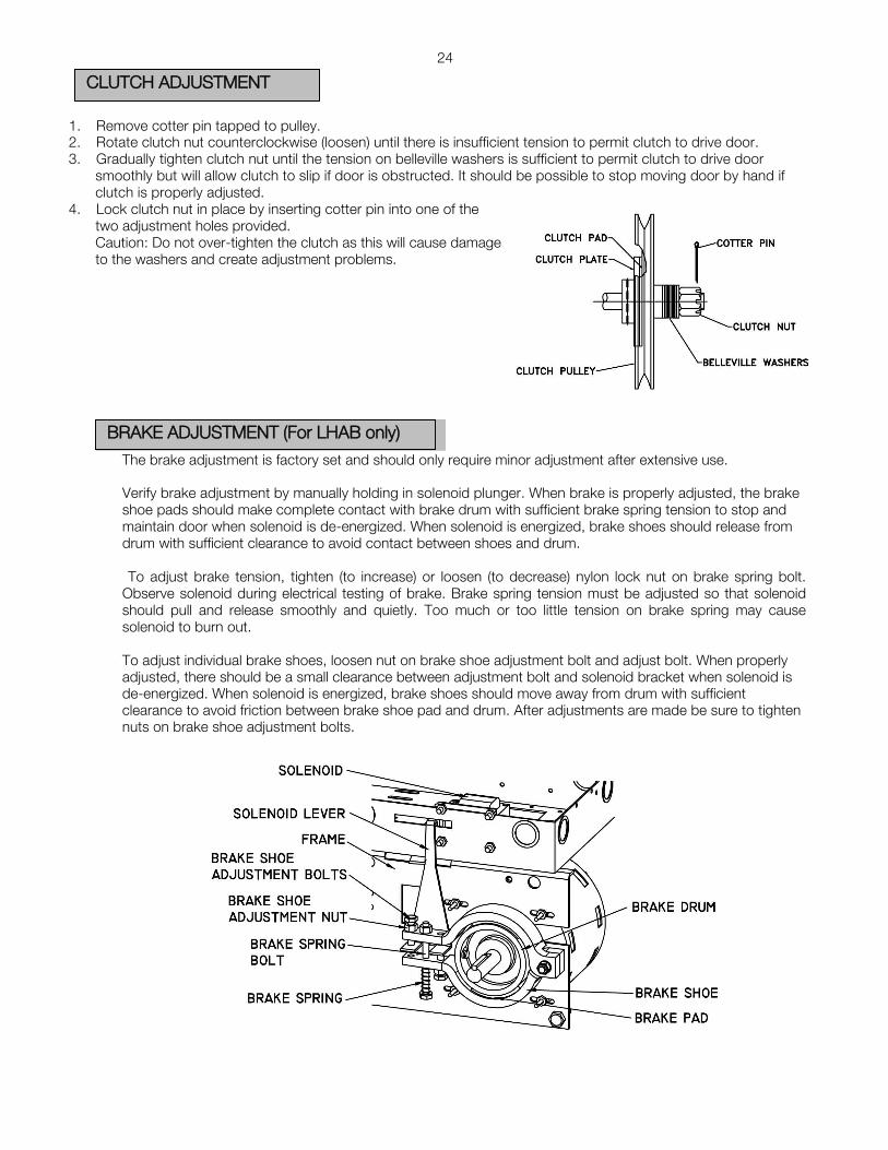
1. Remove cotter pin tapped to pulley.2. Rotate clutch nut counterclockwise (loosen) until there is insufficient tension to permit clutch to drive door.3. Gradually tighten clutch nut until the tension on belleville washers is sufficient to permit clutch to drive door
smoothly but will allow clutch to slip if door is obstructed. It should be possible to stop moving door by hand ifclutch is properly adjusted.
4. Lock clutch nut in place by inserting cotter pin into one of thetwo adjustment holes provided.Caution: Do not over-tighten the clutch as this will cause damageto the washers and create adjustment problems.
The brake adjustment is factory set and should only require minor adjustment after extensive use.
Verify brake adjustment by manually holding in solenoid plunger. When brake is properly adjusted, the brake shoe pads should make complete contact with brake drum with sufficient brake spring tension to stop and maintain door when solenoid is de-energized. When solenoid is energized, brake shoes should release from drum with sufficient clearance to avoid contact between shoes and drum.
To adjust brake tension, tighten (to increase) or loosen (to decrease) nylon lock nut on brake spring bolt. Observe solenoid during electrical testing of brake. Brake spring tension must be adjusted so that solenoid should pull and release smoothly and quietly. Too much or too little tension on brake spring may cause solenoid to burn out.
To adjust individual brake shoes, loosen nut on brake shoe adjustment bolt and adjust bolt. When properly adjusted, there should be a small clearance between adjustment bolt and solenoid bracket when solenoid is de-energized. When solenoid is energized, brake shoes should move away from drum with sufficient clearance to avoid friction between brake shoe pad and drum. After adjustments are made be sure to tighten nuts on brake shoe adjustment bolts.
CLUTCH ADJUSTMENT
BRAKE ADJUSTMENT (For LHAB only)

25
- The PRO-LHA operators are equipped with an emergency disconnect device with interlocked power cut-outswitch to manually operate door in case of emergency. This feature should not be used to manuallyoperate a malfunctioning door.
1. If operator is supplied with standard chain keeper: Pull the disconnect chain through the hole of keyhole andlock in place by inserting chain in slot of keyhole.
2. If operator is supplied with optional floor level disconnect lever: Pull disconnect lever downwards and lock inplace by bending lever around bracket lip as shown.
3. Operate door by pulling on hand chain. To return to electrical operation release disconnect chain and allow toreturn to original position. Lock hand chain in place (to Chain Keeper or Floor Level Disconnect) when not in use.
EMERGENCY MANUAL OPERATION
WARNING
TO REDUCE THE RISK OF INJURY OR DEATH:
DO NOT ATTEMPT TO USE EMERGENCY DISCONNECT SYSTEM WHILE OPERATOR IS RUNNING.
POWER TO THE OPERATOR SHOULD BE TURNED OFF PRIOR TO OPERATING DOOR MANUALLY.

26
- Inspect manual function of the door every 3-months. Make sure that door runs smoothly. If door does notmanually open or close freely, have a qualified service person make repairs. Do not attempt to electricallyoperate a malfunctioning door.
- Every 3 months:
1. Verify that door area is kept clean. Remove any obstructions that would prevent proper dooroperation.
2. Check for any excessive slack in chains. If chain adjustment is required verify and adjust limitswitches, if necessary.
3. Verify and adjust clutch.4. Lubricate chains, bearings and limit shaft.5. Verify that motor and operator runs smoothly and quietly.
- Every 6 months:
1. Verify tightness of all fasteners and set screws.2. Verify that operator is properly secured.3. Inspect manual disconnect.4. Verify tension and condition of V-belt
- Every 12 months:
1. Perform a complete service check.2. Verify that inside of control box is clean and that grounding wires, terminations and power
terminations do not show signs of corrosion.3. Verify tightness of all terminal strip screws and electrical connections.4. Verify power supply, voltage of input terminals during operation.5. Verify that current consumption of operator corresponds to nameplate information
OPERATOR MAINTENANCE
WARNING
TO REDUCE THE RISK OF INJURY OR DEATH:
DO NOT ATTEMPT TO SERVICE THE OPERATOR UNLESS POWER SUPPLY HAS BEEN DISCONNECTED
�
.,,,,,--:/
�
-/
12.1
2.1
1 I
C.S
.I
D.J
, DA
TE:
I AP
PROV
ED:
I DR
A\./N
BY:
UN
LE
SS
□
TH
ER
\JIS
E
SP
EC
IF
IE
D
DIM
EN
SI□
NS
A
RE
IN
IN
CH
ES
TO
LE
RA
NC
ES
.XX
=±
.01
AN
GL
ES
=±
30
'
RE
VIS
IO
N:A
TIT
LE
:
LIM
ITE
D D
UT
Y O
PE
RA
TO
R
PR
O-L
HA /L
HAB
\./E
IGH
T:
lb
SIZ
E:
B P
AG
E:
1/1
CAD
FI
LE
: 3D-
PRDL
HA/L
HAB
ASTA
-XE
I S
CA
LE
:


RADIO RECEIVER
RADIO 2◄V COHACT P□'w'ER
ffl w □ w c:, ...J ....
:i: w >- :,,
I
� Iii ...J >- w ...J w "' w "' :::,>- c:, ,._
:,, □ ...J >-...J w w "' >- c:,
<[
□
29
OPEN CLOSE
0
0
ORANGE I.IHITE
ORANGE ORANGE
GRAY
ORANGE ORANGE
RED
GRAY
BROI.IN
* NOTE: TO REVERSE MOTOR ROTATION INTERCHANGE RED AND YELLOW WIRE ON CAPACITOR.
rl-----+-RED---+--+--+--+--+--+--+--------BLACK--+ --+-+-+-+-+-+- - - - - - - YELLDl.l-+--+-+-+-+-+-+--------
'---l---BLACK---+---+--+--+--+--+--+------� ,-;---BLUE
3-NO 4-NO ----+-+,z :,, □ "' "'
"' u <[ ...J "'
2◄ VAC. PO\IER
STOP C04 IP(N CLOS£ SAFETY DEVICE
CO<
� L...__ PUSH-BUT�------'
2
_&. WARNING Ml CANAN STRONGLY RECOMMENDS THE USE OF ENTRAPMENT PROTECTION SYSTEMS WHEN 82 (MOMENTARY CONTACT) WIRING IS USED.
I-PHASE PRo-LHA l/2HP II0VMSLHA-WW
REV. F I DATE: 08.08.09 TECH. HELP LINE: CANADA: 1-(877) 888-1116
USA: 1-(888) 816-8584
3 4 5 6 7 8 9
CONTROL WIRING OPTION ON CLOSE:
PD'JER SUPPLY USV, 1 PHASE, 60 Hz
THIS OPERATOR LEAVES THE FACTORY WITH A ·cz· WIRING - MEANING THAT CONSTANT PRESSURE IS REQUIRED TO CLOSE THE DOOR. IF MOMENTARY OPERATION ON CLOSE - ·sz· WIRING - IS DESIRED, THEN RE-INSTALL THE PURPLE WIRE ON TO TERMINAL #5.
EXTERNAL SINGLE PUSH-BUTTOi STATJOi !Nlt:Rl.00(
fr R£MIJVE rACTDRY
INST AU.ED ...l..WER Jr EXTERNAL
INTERLOCK DEVICE IS REQUIRED.
PLACE A toMALLY CLOSED SCT CF VIRES ACROSS
THESE nro TERMINALS,
n,a PUSH-BUTTON STATIDN SAf"ETY EDGE <N.C. C�TACT)
SAFETY REV£RSE DEVICE
CAPACITOR 70UFD
240VAC
z w w "' c:,
1 GROUND
1:,. IF STOP BUTTON NOT USED, I.£:::. ADD JUMPER BETWEEN 2 8, ;5.
NOTE: MINIMUM 18 AWG WIRE MUST BE USED FOR FIELD CONNECTIONS.
IPEN-CLOSE OCVICE
OUl. CONTACT>
CPEN-0..0SE �ND
RADJC RECOVER
ff 2◄ v;,,c PO\l[R
AVAILBLC: !OVA HAX.
THE INFORMATION CONTAINED HEREIN IS PROPRIETARY TO MICANAN SYSTEMS INC. AND SHALL NOT BE REPRODUCED OR DISCLOSED OR USED FOR ANY DESIGN OR MANUFACTURE EXCEPT WHEN USER POSSESSES DIRECT WRITTEN AUTHORISATION FROM MICANAN SYSTEMS INC.

RADI□RECEIVER
1 2 3
ln__fu'l RAD!□
2-4V CONTACT P□!JER
L1 cj z z
..J "'
( □PEN )COM/ I
Q □PEN �;□•LIMIT C S',;ITCH Q 1--· --+--+--,
�
�
:.. "' "' �"' "'
I A A
� w
ADVANCED Ql�N�-�C�·=====-----+f--+-+-+-DPEN I
J
0 slJriJH �N""',=
□.:.._• - --+--+__J
I COM
l
.----
--+
-t--+-
--'l{HITE-+--+f--t--c=:J
16-::, L,__
Q
l{HITE
"' "' n
"' ... <J> n
GRAY
0---i
<� :,,z "' (J1..., o□ ' "' "'� of'l :,::,O
CLOSE
I
CLOSE
�� 0
1 N.C.10
LIMIT S',;ITCH
N,C. N.□.
.,,�"'"'� n
�
� 0 ADVANCED
CLOSE LIMIT
S',;ITCH I
COM
=-
ol
* NOTE: TO REVERSE MOTOR ROTATION INTERCHANGE RED AND YELLOW WIRE ON CAPACITOR.
CAPACITOR 20UFD
370VAC
6 t!J .---+---+---+- - -YELL□l{ -- --+-- -+---+--+-- - - --+--l -+-I _ _ _ _ �
.------u-----
+----
t--+--+--
-il-
+--+--+-������������������
��
:
-+-,
�,---7� i � I I <t □ _J A
...... r---r-\ � 1-NC 2-NC !.--
+-
--
--+
-
+--+
--
+--+---+
-
+--
-
� :i: - - =i 1� 3
� T� �� � � � tc__
----!-----<3•--N□ 4-N□ f .----+-'-
5-_..,
c ... □M 6� J � B B F= 4 5 6
-
7 8 9 n MOTOR n
8 □ 1/2 HP,220V □ 10 D 11
I 24 VAC
C� a-a
/\.......r,____/ -ORANGE---+-+--+--+----+-+---+--+--+-� B B F=
R R VIDLET
u <[
2-4 VAC P□'w'ER
l l □ □ >-..J ..J <[ "
ST□P C□H OPEN CLOSE L--- PUSH-BUTT□NS_____,J 2 3 4 5
=-□
SAFETY IEVJCE
6
C□M
7
L,J �
□PEN CLOSE
8
l L,J "' z z ., .,
2-4 VAC
9
"' =- u □ ., ..J "' "' "'
1 GROUND
� POWER SUPPLY
220V, 1 PHASE, 50/60 Hz
_&. WARNING
MICANAN STRONGLY RECOMMENDS THE USE OF ENTRAPMENT PROTECTION SYSTEMS WHEN B2 (MOMENTARY CONTACT) WIRING IS USED.
CONTROL WIRING OPTION ON CLOSE: .&. THIS OPERATOR LEAVES THE FACTORY WITH A "C2" WIRING - MEANING THAT CONSTANT PRESSURE IS REQUIRED TO CLOSE THE DOOR.
/.:;. IF STOP BUTTON NOT USED, 1£::,, ADD JUMPER BETWEEN 2 & 3.
PRo-LHA l/2HP 22OV 5O/6OHZ 1-0 MSLHA2-WW
REV. C DATE: 24.08.11
TECH. HELP LINE:
CANADA: I- 877 888-1116 USA: I- 888 816-8584
IF MOMENTARY OPERATION ON CLOSE - "B2" WIRING - IS DESIRED, THEN RE-INSTALL THE PURPLE WIRE ON TO TERMINAL #5.
NOTE: MINIMUM 18 AWG WIRE MUST BE USED FOR FIELD CONNECTIONS.
EXTERNAL SINGLE PUSH-BUTT□N STATION INTERLOCK
RDIJVE FACTIRY INSTALLED
..I.IMPER IF EXTERNAL INTERLOCK DEVICE
IS REGUIRED. PLACE A NCRMALL Y
CLOSED SET or 'JIRES ACROSS
TIES£ T'wD TERMINALS.
T'w□ PUSH-BUTTON STATICIII SAFETY EDGE OPEN-CLOS£ CN.D. CCIIITACT> DEVICE
SAFETY REVERSE DEVICE
(N.n CONTACT)
OPEN-CLOSE cc:t4HAND
RADIO RECEIVER
m 24 VAC pa..,,:R
24 VAC PO...,.
AVAILBLE lOVA MAX.
THE INFORMATION CONTAINED HEREIN IS PROPRIETARY TO MICANAN SYSTEMS INC. AND SHALL NOT BE REPRODUCED OR DISCLOSED OR USED FOR ANY DESIGN OR MANUFACTURE EXCEPT WHEN USER POSSESSES DIRECT WRITTEN AUTHORISATION FROM MICANAN SYSTEMS INC.

RAD!□RECEIVER
I 2 3
LJI.JL
□PEN ) COM �--ORANGE---------ORANGE COM ( CLOSE ) ,----!° ,:::��::-
N-.O
-.--U-RANGE -- --ORANGE-- -�--,
O OPEN N;d0· CLOSE O
I LIMIT N C N C LIMIT S'JITCH Q ' ' GRAY----� -RED ' ' Q S'JITCH
llE
BRAKE �Ir USED>
RAD!□ 24V C□NTACT P□IICR � � t
□-2 [jjzy •! BLUE
/
:::: :: RED )
I@,.� If 10..,i I � � ADtt��ED Q
0 LIMIT
N.C.
N.O. BLACK- - - --+--+->--
---+- --BLACK --',/HITE BLUE-----+�
N.C. o ADVANCED
O l CLOSE
N.0. LIMIT
SEE C□RRESP{JI.IDJt«j ASTERISKS � REVERSING STARTER, 'IJ" DENJTES 'ClPEN' SIIE IJf" REVERSING STARTER,
"' D f--0 ::,:
5 � \,i! S'JITCH ...J I <t I !:! :,. g; COM "- 'JHITE�
S\IITCH ,---,r-+---+--+-+-t-- -BRO'JN-- - --
C-□_.�
I I
'----'JHITE:----7
I �----------------ORAN�=-._____J--+--+-+-1+-<-�
------------------:Rig�� L...fl--+
-+- -
---+-
+-- -'�����E-------------
� 0 u
u
� I- 0 (/) _, -Ct: Ow I
t-�
BLACK
w (/) :::,
�
:,. WD f-- .J - .J :,: w
-----YELL□'w----+-----+---+--·y[LL□1J-.. ------------1-------� -BRO'JN RO'JN-----------�
'e:!J le::_� I 3 n 5
I I
\I I I
'e:!. � L� I n 3 5
□PENC□)
TI � �
CLDSECC)
: ®
t---@ I I
Ll � "'?
I I J
I
z :,.
2 U 4 6 fn ml lflll
w f--i :,.
FUSE 2A.
� ----.._ --. I -NC 2-NC -
3�□ 4-N□.,,-V-
5-c□M 6-C□�V '------t-=---7 R 1-.. •-::-+--+-�
�+--+---<>--+--+--+--,>--- - - - - - -
---+---,./ 24 VAC r-+--+-,f--+---+---+-,f--- - - - - - -�' \_r-._/ '�-+-1--,
n
�------RED-
� PURPLE--+-----8-----+-PURPLE
& TIME DELAY 1.5 Sec
(OPTIONAL)
(D
i r /&. I
NOTE:TO REVERSE MOTOR DIRECTION INTERCHANGE ANY 2 OF THE 5 INCOMIN POWER LINES CONNECTING TO POWER SUPPLY TERMINAL STRIP LI, L2, L5.
GROUND
___L_ 2-J VA£ Pll\JER
.&_ WARNING
STOP COM !FEN CL.DSE L--- PUSH-llUTTONS-----J
2 3 4 5
SAFETY DEVICE E,
COM
7
8 9 0 0 L1 L2 L3 0 d_, � 9 � fi d_, f4? 9
�� t?'.��
IPEN CLOSE
8 9
cl=:t=p-0 � POWER SUPPLY
380V, 3 PHASE, 50 Hz
CONTROL WIRING OPTION ON CLOSE: Ml CANAN STRONGLY RECOMMENDS THE USE OF ENTRAPMENT PROTECTION SYSTEMS WHEN 82 (MOMENTARY CONTACT) WIRING IS USED.
THIS OPERATOR LEAVES THE FACTORY WITH A 'C2' WIRING - MEANING THAT CONSTANT PRESSURE IS REQUIRED TO CLOSE THE DOOR. IF MOMENTARY OPERATION ON CLOSE - '82' WIRING - IS DESIRED, THEN REMOVE THE WHITE WIRE FROM TERMINAL #5 AND PLACE ON TERMINAL #3.
& TIME DELAY UPON REVERSE. IF 1.5 SEC TIME-DELAY UPON SAFETY REVERSE IS REQUIRED. REMOVE THE PURPLE WIRE FROM TERMINAL #4 , AND CONNECT TO ONE END OF TIME-DELAY AND OTHER END, BACK TO TERMINAL #4.
A IF STOP BUTTON NOT USED, � ADD JUMPER BETWEEN 2 a 3.
NOTE: MINIMUM 18 AWG WIRE MUST BE USED FOR FIELD CONNECTIONS.
3-PHASE PR0-LJ/LH/L T /LHA/GJ EXTERNAL INTERLOCK SINGLE PUSH-BUTT□N STATION TlJD PUSH-BUTTDN STAT� SAFETY EDGE
(N.D. CCNTACT> DPEN-CLDSE RADm RECEIVER 2-4 VAC DEVICE
mPD\/ER
l/2HP 380V 50HZI REV. E MS300LH-WW IDATE: 29.01.07 TECH. HELP LINE: CANADA: 1-(877) 888-1116
USA: l-<888) 816-8584 REtlJVE FACT�Y INSTALLED ...UMPER IF' EXTERNAL INTERLOCK DEVICE JS REQUIRED, PLACE A t,,IJRNALLY CLOSED SET or IJIRES ACROSS Tt£SE TIJD TERMINALS,
1°1'-r-=TJ I CLOSE-1 I
_j_
<N.ll CONTACT>
� � "fOPEt4 I CLOSE-2I I� _j_
I 2-4 VAC SAF'ETY Plllo'ER
REVERSE CPEN-CL□SE AVAILBLE IEVICE � 10VA MAX.
THE INFORMATION CONTAINED HEREIN IS PROPRIETARY TO MICANAN SYSTEMS INC. AND SHALL NOT BE REPRODUCED OR DISCLOSED OR USED FOR ANY DESIGN OR MANUFACTURE EXCEPT WHEN USER
POSSESSES DIRECT WRITTEN AUTHORISATION FROM MICANAN SYSTEMS INC.

□PEN CLOSE
RAD!□RECEIVER
� -- -�1t1r1r1
� NOTE: � � g CONTROL WIRING OPTION ON CLOSE: � � � THIS OPERATOR LEAVES THE FACTORY WITH A 'C2' WIRING - MEANING THAT CONSTANT PRESSURE IS REQUIRED TO CLOSE THE DOOR. IF MOMENTARY OPERATION ON CLOSE - 'B2' WIRING - IS DESIRED, THEN RE-INSTALL THE PURPLE WIRE ON TO TERMINAL 415.
ill IF STOP BUTTON NOT USED, ADD JUMPER BETWEEN 2 a 5.
_& MICANAN PHOTO-BEAMS (OR MICANAN COMPATIBLE MONITORED REVERSING DEVICES) MUST BE CONNECTED FOR THE DOOR TO CLOSE IN MOMENTARY MODE. IF MONITORED REVERSING DEVICES ARE NOT CONNECTED, DOOR CAN ONLY BE CLOSED BY CONSTANT PRESSURE ON CLOSE AND IF CONSTANT PRESSURE ON CLOSE IS REMOVED BEFORE DOOR REACHES FULL CLOSE POSITION, DOOR REVERSES TO FULL OPEN. NOTE: ONLY ONE MONITORED DEVICE CAN BE CONNECTED TO Pl AND P2
& ANY SECONDARY REVERSING DEVICE(S) WITH A N.O CONTACT CAN BE INSTALLED TO SI AND S2. DO NOT REMOVE RESISTOR UNLESS INSTALLING ON A 4-WIRS ELECTRIC EDGE.
I I
ci'J > □ w ...Jw " ...J "' :::, w "' LL >-
-
-
�----□RANGE -----------□RANGE
...---� -- ---□RANGE □RANGE- --�---.
GRAY·---->->->->----GRAY
t--=-- -GRAY
�:=:.-- -BLUE �--�--� .. C
.. □M-�- - --1/HITE
\/HITE I □RANGE
1/HITE_J \/HITE GRAY GRAY--
u ci
1/HITE
n n
\/HITE
z z SEC 24VAC "' w.;:;:;
"' u :{❖
I If-0 u (,O...J TRANSFORMER . <[ -oe ...J □w � "' :,: f-
i'S •:.•:.•.
=
lJ
� I 2 '.V -
1"- 4 � -
� � -
� >->--10�!
/ 24 VAC �
40 VA -······:;
PR! !ISVAC =
w :::, ...J "'
RED LBLACK
�YELL□\/
RED BLACK BLUE-
l t:;
� I-NC 2-NC - -3-N□ 4-N□
:,: �---
f 5-C□M 6-C□M
-7
� / 24 VAC
-L/ �__J
w w > "' w w ...J D "' >- z f- f- w "- ...J u <[ <[ 'i' A 'i' :::, "' ...J <[ "' "' w ...J:::, w ...J "' D > "' > "'"- >- "'
WW w "' "' w ...J □ "' >- zz f- w "- ...J u <[ <[ <[ 'i' :::, "' ...J <[ "' "'"' ...J:::, w ...J "' □□ > "'"- >- "'
1l □ ...J ...J "- >- w ...J"' <[ :::, w :::, "'...J >- "- �'i' I I
INTERFACE MODULE
Ji Ji L!:"' "' "' u zz > ><[ <[ <[ DD ...J "'"' "'"' "' D D "'"'
_J L _
I w w "' "' z "' "' z z uz > z u > ><[ <[ □ <[ <[ □ □...J"' "' "' ...J"' "' "'□ "' □ "'"' "'
£ ������\���l��:C
� AFTER -
ADJUSTING THE LIMITS. BEFORE CONNECTING BLACK WIRE TO TERMINAL I. DOOR CAN BE CLOSED BY CONSTANT PRESSURE BY JUMPING TERMINALS 5 AND 6.
NOTE: MINIMUM 18 AWG WIRE MUST BE USED FOR FIELD CONNECTIONS.
"'"'
I-PHASE PRO-LHA l/2HP IIOVMSLHA-IM-WW
REV. H I DATE: 17.11.10 TECH. HELP LINE: CANADA: H877) 888-1116
USA: 1-(888) 816-8584 ......
>> � � WW w "'"'"' □□ >- "-W "- f- zzu
EXTERNAL INTERLOCK
u REMOVE F'ACTCRY
INSTALLED
Jl.14PER IF EXTERNAL INTERLOCK
DEVICE IS REQUIREn PLACE A NCRHALLY
CLOSED SET □F' \/IRES ACROSS Tl-£SE
T'JD TERMINALS.
SINGLE PUSH-BUTTON STATmN
l l z z "' "' > > z z □ □
MICANAN F'AIL-SAF"E PHJTD BEAM
z > "'"' uu<[ <[ ...J ...J "'"'
� P□'JER SUPPLY
IISV, I PHASE, 60 Hz
SAFETY EDGE
(N.n CDNTACT>
SAFETY REVERSE DEVICE
!FEN-CLOSE
DEVICE
(N.D, CONTACT>
CPEN-C1..0SE C[Ji4tw-lD
A w "'
A w "'
w f-
'i' >
w f-
'i' >
* NOTE:
TO REVERSE
MOTOR
ROTATION
INTERCHANGE
RED AND
YELLOW WIRE
ON CAPACITOR.
CAPACITOR
70UFD
240YAC
zw w
RADI□ RECEIVER
GROUND
TT 24 VAC PIMJ>
AVAILBLE
!OVA HAX.
THE INFORMATION CONTAINED HEREIN IS PROPRIETARY TO MICANAN SYSTEMS INC. AND SHALL NOT BE REPRODUCED OR DISCLOSED OR USED FOR ANY DESIGN OR MANUFACTURE EXCEPT WHEN USER POSSESSES DIRECT WRITTEN AUTHORISATION FROM MICANAN SYSTEMS INC.

RADID RECEIVER
I 2 3
OPEN ( CLOSE ) -RED- - --
�-COM
CLOSE
*NOTE:
lrLn__n_ [Q □PEN
LIMIT SI/ITCH
l,!::!.O,
OIN,C, GRAY-- -+-, -RED N.□. Ql N,C, O s'iJf-lJH
TO REVERSE MOTOR ROTATION INTERCHANGE RED AND YELLOW WIRE ON CAPACITOR.
£ NOTE,
1r1r1r1 z t- _J <[ - _J "' :,: w□ :,, >-
� � ,,--GRAY -
[
ADVANCED Q 1 N,<./ GRAY----+-i----+-+- -GRAY □PEN I ,o_,...,------RED- - --+--+---' 0 s'iJfNH J
N, RED -
�
� N,C, o ADVANCED
l CLOSE
N.□.
s'ilfNH 0 I --GRAY------,
C"'O
,_.�
CAPACITOR 20UFD
370VAC
CONTROL WIRING OPTION ON CLOSE, THIS OPERATOR LEAVES THE FACTORY WITH A ·cz· WIRING - MEANING THAT CONSTANT PRESSURE IS REQUIRED TO CLOSE THE DOOR.
COM "'---
---
\IHITE\IHITE
l < )f-;i!E IF MOMENTARY OPERATION ON CLOSE - 'B2' WIRING - IS DESIRED, THEN RE-INSTALL THE PURPLE WIRE ON TO TERMINAL #5.
IF STOP BUTTON NOT USED, ADD JUMPER BETWEEN 2 a 5.
& MICANAN PHOTO-BEAMS (OR MICANAN COMPATIBLE MONITORED REVERSING DEVICES) MUST BE CONNECTED FOR THE DOOR TO CLOSE IN MOMENTARY MODE. IF MONITORED REVERSING DEVICES ARE NOT CONNECTEO, DOOR CAN ONLY BE CLOSED BY CONSTANT PRESSURE ON CLOSE AND IF CONSTANT PRESSURE ON CLOSE IS REMOVED BEFORE DOOR REACHES FULL CLOSE POSITION, DOOR REVERSES TO FULL OPEN. NOTE, ONLY ONE MONITORED DEVICE CAN BE CONNECTED TO Pl AND P2
& ANY SECONDARY REVERSING DEVICE($) WITH A N.O CONTACT CAN BE INSTALLED TO SI AND S2, DO NOT REMOVE RESISTOR UNLESS INSTALLING ON A 4-WIRS ELECTRIC
EDGE.
£ ���:��T
T���l���C
� AFTER
c..i z "" u t- □ "'_J
a�:,: t-
□ z
�-
-- ,------,f--t--RED RESISTANCEL__
2 □HM, 25WI
,-,f---------+---f--+-+--+--+-+--YELLD\l---------1-'
.J. ��
I _2 3 '-+:._f-_---1_,f--_ -...,.-____
4
3 4 ---- ->--+---, 5
L_-+------5- -6---+----!-+-, _ � IO 11 .. 12---l
----+-+-
+---'
13 '1-----fol..-.114
..-,-+-+-+-+-+---/,I' ?2449 VAACC "' -�
( �' / � i f----+�
I I�
l l �� I � �
� I i: ,-
�
MOTOR � 1/2 HP ,-
220 VAC 50/60 HZ I-
I a �� �
SEC 24VAC
ITRANSFORMER 40 VA, S0/60 HZ
i'ZYH
ADJUSTING THE LIMITS. BEFORE CONNECTING BLACK WIRE TO TERMINAL I. DOOR CAN BE CLOSED BY CONSTANT PRESSURE BY JUMPING TERMINALS 5 AND 6.
r□ �---+-+-+-+--+-+------<-----<-----<--+--+--+---------f INTERFACE PR! 220VAC
NOTE, MINIMUM 18 AWG WIRE MUST BE USED FOR FIELD CONNECTIONS.
PRo-LHA l/2HP 220V 50/60HZ IQ MSLHA2-IM-WW
REV. B I DATE: 24.08.11 TECH. HELP LINE: CANADA: 1-(877) 888-1116
USA: 1-(888) 816-8584
EXTERNAL INTERLOCK
u REMOVE F"ACTCRY
INSTALLED JUMPER IF EXTERNAL
JNT£RLDCK DEVICE IS REQUIRED. PLACE A NIRHALL Y
CLOSED SET OF" 'w'IRES ACRDSS Tl-ESE
TW TERMINALS.
w ...J w a_
:::, A °'
SINGLE PUSH-BUTTON STATIDN
w '-" z <[ "'
\.
z :,, □
I
MODULE
z :,, □
MICANAN F"AlL-SAFE PI-IJT□ BEAM
\/HITE
z y y :,, u u □ <[ <[ "' ...J ...J "' "'"'
� POI/ER SUPPLY
220V, I PHASE, 50/60 Hz
SAFETY EDGE (N.n c□NTACD
SAf"ETY REVERSE DEVICE
CPEN-CLDSE DEVICE
(N.D. CONTACT)
[PEN-CLOSE Cctl�D
I
RADI□ RECEIVER
J
z w w "'
GROUND
24 VAC PllVER
AVAILBLE tOV" Mf\X.
THE INFORMATION CONTAINED HEREIN IS PROPRIETARY TO MICANAN SYSTEMS INC. AND SHALL NOT BE REPRODUCED OR DISCLOSED OR USED FOR ANY DESIGN OR MANUFACTURE EXCEPT WHEN USER POSSESSES DIRECT WRITTEN AUTHORISATION FROM MICANAN SYSTEMS INC.

BRAKE SOLENOID (IF USED>
* □-2 [lj2iJ •1 --1----- -- --+-�
BLUE 380 VAC
::: : :: RED }{��:Et MOTOR
SEE C□RRESP□NDING ASTERISKS □N REVERSING ST ARTER. •□• DENOTES '□PEN' SIDE □F REVERSING ST ARTER,
NOTE: (I) TO REVERSE MOTOR DIRECTION INTERCHANGE ANY 2 OF THE 5 INCOMING POWER LINES CONNECTING TO POWER SUPPLY TERMINAL STRIP LI, L2, L5.
NOTE: @/@ CONTROL WIRING OPTION ON CLOSE:
THIS OPERATOR LEAVES THE FACTORY WITH A ·cz· WIRING -MEANING THAT CONSTANT PRESSURE IS REQUIRED TO CLOSE THE DOOR.
IF MOMENTARY OPERATION ON CLOSE ("B2" WIRING) IS DESIRED, THEN REMOVE THE WHITE WIRE FROM TERMINAL #6 AND PLACE IT ON TERMINAL #5.
& TIME DELAY UPON REVERSE. IF 1.5 SEC TIME-DELAY UPON SAFETY REVERSE IS REQUIRED. REMOVE THE PURPLE WIRE FROM TERMINAL #4 AND CONNECT TO ONE END OF TIME-DELAY AND OTHER END, BACK TO TERMINAL #4.
& MICANAN PHOTO-BEAMS (OR MICANAN COMPATIBLE MONITORED REVERSING DEVICES) MUST BE CONNECTED FOR THE DOOR TO CLOSE IN MOMENTARY MODE. IF MONITORED REVERSING DEVICES ARE NOT CONNECTED, DOOR CAN ONLY BE CLOSED BY CONSTANT PRESSURE ON CLOSE AND IF CONSTANT PRESSURE ON CLOSE IS REMOVED BEFORE DOOR REACHES FULL CLOSE POSITION, DOOR REVERSES TO FULL OPEN. NOTE: ONLY ONE MONITORED DEVICE CAN BE CONNECTED TO Pl AND P2
& ANY SECONDARY REVERSING DEVICE(S) WITH A N.O CONTACT CAN BE INSTALLED TO SI AND S2. DO NOT REMOVE RESISTOR UNLESS INSTALLING ON A 4-WIRE ELECTRIC EDGE.
BLACK
RAD!□ RECEIVER
lf\r\_n
� [ CLOSE)
I
COM ,,.---�-------rJRR,:�:---+--+---�::���----...____----',_c_o_M_
I
0 �,0, N:�0, □PEN CLOSE Q LIMIT s-.,ncH
0 ..,N_._c_. - --GRAY- -RED - - - -N_._c .
-tOLIMIT s'JITCH
� �
ffl �O ..,N_,;;:;c ''---BLACK--+-t--t-+--BLACK ------:, ... N_.c-1, O �
t!l w □
O LIMl��ITCH t-N-"'"'o'-, --BLUE--+-+-� -'JHITE N� uMN�t'iTcH O
z 1- ...J I I � 5: ci ,__..,,. _____ ,IJHITE-
�
-GRAY --------"
I I >- COM -------- 'JHIT
�� COM
�-+-+-----------------<J:RANGE -',/HITE -----� �+----------------'JHITE 'JHITE- - - -�
.--+----------------YELL□IJ'--,t-+-t--+-t--·YELL□lJ-- - - - - - - - - - - - --RED,- -+-1-+-�
- -- - - - - - - - --BLUE--+-+--+� -- - - --BLUE- -+-+--+�
r---GRAYBRDIJN-
....__GRAY -->-+--� � -- - -RED,- -+-f-- - -�
�----PURPLE-�- - - - - - - - - --+-- - - - -BLUE
REVERSING RELAY
24 VAC
& TIME DELAY
1.5 Sec (□PTl□NAL>
r'r--1-NT_ E_R_FTA_C_E_M□
-DrU-L_E_---,,
r-+----8-FUSE 2A,
-o=u----�
n
TRANSFORMER 50 VA, 50/60HZ
SEC 24VAC
CONNECT THE BLACK WIRE TO TERMINAL 1 AFTER ADJUSTING THE LIMITS.
, � r;i 0 0 � {f, (L, (L, � � � � � GROUND � �
"��;;....J....�;:;;;,2 ...i....;;;�i;:;.....1-�..;:;4;.........;�:;;;.5 ...i....;;i�;;;........�,;:;:;7.......;;2;:;.,.....rP..;:;P2;...J....;v::;;.i...i....;;i�.;..2 .i...��Sl--� --=-- � � ■ I
NOTE: MINIMUM 18 AWG WIRE MUST BE USED FOR FIELD CONNECTIONS.
L_j ____ )-� I \ & I :
� 2-4 VAC STOP C[l,f OPEN CLOSE PDW'ER L.__ PUSH-BUTTCNS______J
CPEN 2-4 VAC CL□SE
2 3 4
3-PHASE PR0-LJ/LH/L T /LHA/GJEXTERNAL INTERLOCK
l/2HP 380V 50HZ REV. A
u MS300LH-IM-WW DATE: 20.01.11
TECH. HELP LINE:
CANADA: I- 877 888-1116
USA: I- 888 816-8584 REltlVE FACTtRY INSTALLED .JUri4PER IF EXTERNAL
INTERLOCK DEVICE IS REQUIRED. PLACE A l'GMALL Y
CLOSED SET CF' IJIRES ACROSS Tl-£SE
TW TERMINALS,
5 6 7 8
SINGLE PUSH-BUTTCN STATmN HICANAN KINITIRED PHDTD BEAM
GRAY
SAFETY EDGE CN.C. Cl>4TACT>
2:5 SAFETY
REVERSE DEVICE
□PEN-CLOSE DEVICE
(N.D. Cl>4TACT>
2:5 DPEN-CLOSE
CCtfrilAND
POWER SUPPLY
380 VAC. 3 PHASE. 50 Hz
2◄ VAC RADI□ RECEIVER Pll'JER
RADIO
?r RECEIVER
16161@1 24 VN:. PO\/ER
AVAILllt.E !OVA MAX.
THE INFORMATION CONTAINED HEREIN IS PROPRIETARY TO MICANAN SYSTEMS INC. AND SHALL NOT BE REPRODUCED OR DISCLOSED OR USED FOR ANY DESIGN OR MANUFACTURE EXCEPT WHEN USER POSSESSES DIRECT WRITTEN AUTHORISATION FROM MICANAN SYSTEMS INC.

� IF STOP BUTTON USED, REMOVE JUMPER BETWEEN "STOP" AND "COM' TERMINALS.
D,. MICANAN f..£::::. MONITORED PHOTC BEAMS OR MICANAN COMPATIBLE MONITORED SAFETY DEVICES MUST BE CONNECTED TO Pl AND P2 FOR THE DOOR TO CLOSE IN MOMENTARY MODE (B2 OR TS). IF MONITORED SAFETY DEVICES ARE NOl CONNECTED, DOOR CAN ONLY BE CLOSED BY CONSTANT PRESSURE AND IF CONSTANT PRESSURE IS REMOVED BEFORE DOOR REACHES FULL CLOSE POSITION, DOOR REVERSES TO FULL OPEN POSITION. NOTE: ONLY ONE MONITORED DEVICE CAN BE CONNECTED TO P2 AND Pl.
A ONE OR MORE � SECONDARY SAFETY DEVICES (WITH A N.O. CONTACT) CAN BE CONNECTED TO SI AND S2.
I.\ DOT NOT REMOVE � RESISTOR UNLESS INSTALLING ON A 4-WIRE ELECTRIC EDGE.
A REFER TO � INSTALLATION
MANUAL FOR APPROPRIATE SURGE PROTECTOR RATINGS.
J>... OPERATOR IS ill SHIPPED FROM FACTORY IN CONSTANT PRESSURE TO CLOSE (C2) MODE OF OPERATION. IF MOMENTARY ON CLOSE IS REQUIRED, REMOVE THE JUMPER FROM PIN"C2' AND PLACE IT ON PIN'B2" IF TIMER TO CLOSE IS REQUIRED, PLACE THE JUMPER ON PIN'TS".
A TIMER TO CLOSE Li:),, ADJUSTMENT: DEFAULT SETTING OF TIMER TO CLOSE IS 5 SEC. TO MODIFY THIS VALUE, PRESS 'TIMER PROGRAM' BUTTON UNTIL DESIRED VALUE IS REACHED. REFER TO ON BOARD LED INDEX FOR TIMER VALUE INDICATION
RADID RECEIVER
SEC 2-t. VAC
TRANSF□RMER ◄OVA
BRAKE S□LEN□ID
l!OVAC
IF USED
I-PHASE 110 VAC
MSLLHRII0V-WW REV. C DATE: 02.01.13
TECH. HELP LINE:
CANADA: I- 877 888-1116
USA: I- 888 816-8584
0
0
N.0,
OPEN
.,,.CO_,M,__ ___ GRAY
YELL□'w
COM
H□IST COM INTERL□CK
N,C, IF USED
0
[Q][Q][Q] OPEN CLOSE STOP
::E [)._
□ □ u I-
Vl I
/ --
\ POWER YSUPPLY J 11 0 v;c,, 1 PHASE. 60 Hz
LED
"01. / "
POw'ER
z w [)._ □
CLOSE
RED-------C_
O..;M
LACK
BLUE
w Vl □
u
0 H2
RADIO
Hl LIMIT
S\,/ITCH
TS
LED
'0. / "
FAULT
B2
(\J a: [)._
MICANAN MONITORED
PHOTO-BEAM
>« ...J w "'
z w [)._
ooeeooe•ru:O: 0
oooo••••M::O:
!OK OHM
& (\J
GR□UND
....
), Vl
u «
b
*NOTE: TO REVERSE MOTOR ROTATION INTERCHANGE RED AND YELLOW WIRE ON CAPACITOR.
INTERLCCK SINGLE PUSH-BUTTON STATICJi MICANAN HJ:l,IITCRED PHDT□ BEAM
SAFETY DEVICE 24 W,C, P[l'JER SINGLE BUTTON
REKIVE rACTDRY INSTALLED Jl.NPER IF EXTERNAL INTERLOCK
DEVICE IS REQUIRED. PLACE A NORMALLY
CLOSED SET CF IJIRES ACROSS Tl£SE
TVD TERMINALS,
SAfETY
REVERSE DEVICE
(Nil CONTACT)
24 VAC POI/ER
AVILABLE SINGLE BUTT� 10 VA, MAX. (N.a. CONTACT)
CAPACITOR
70UFD 240VAC
RADIO RECaVER
RADIO RECEIVER
THE INFORMATION CONTAINED HEREIN IS PROPRIETARY TO MICANAN SYSTEMS INC. AND SHALL NOT BE REPRODUCED OR DISCLOSED OR USED FOR ANY DESIGN OR MANUFACTURE EXCEPT WHEN USER POSSESSES DIRECT WRITTEN AUTHORISATION FROM MICANAN SYSTEMS INC.

& IF STOP BUTTON USED, REMOVE JUMPER BETWEEN "STOP" AND "COM" TERMINALS.
RADIO RECEIVER
A. MICANAN f..£::::. MONITORED PHOTC BEAMS OR MICANAN COMPATIBLE MONITORED SAFETY DEVICES MUST BE CONNECTED TO Pl AND P2 FOR THE DOOR TO CLOSE IN MOMENTARY MODE (B2 OR TS). IF MONITORED SAFETY DEVICES ARE N01 CONNECTED, DOOR CAN ONLY BE CLOSED BY CONSTANT PRESSURE
ltl�l11
AND IF CONSTANT PRESSURE IS REMOVED BEFORE DOOR REACHES FULL CLOSE POSITION, DOOR REVERSES TO FULL OPEN POSITION. NOTE: ONLY ONE MONITORED DEVICE CAN BE CONNECTED TO P2 AND Pl.
A ONE OR MORE � SECONDARY SAFETY DEVICES (WITH A N.O. CONTACT) CAN BE CONNECTED TO SI AND S2.
I.\ DOT NOT REMOVE � RESISTOR UNLESS INSTALLING ON A 4-WIRE ELECTRIC EDGE.
A REFER TO � INSTALLATION
MANUAL FOR APPROPRIATE SURGE PROTECTOR RATINGS.
I.\. OPERATOR IS ill SHIPPED FROM FACTORY IN CONSTANT PRESSURE TO CLOSE (C2) MODE OF OPERATION. IF MOMENTARY ON CLOSE IS REQUIRED, REMOVE THE JUMPER FROM PIN"C2" AND PLACE IT ON PIN"B2" IF TIMER TO CLOSE IS REQUIRED, PLACE THE JUMPER ON PIN"TS".
� TIMER TO CLOSE ADJUSTMENT:
DEFAULT SETTING OF TIMER TO CLOSE IS 3 SEC. TO MODIFY THIS VALUE, PRESS 'TIMER PROGRAM' BUTTON UNTIL DESIRED VALUE IS REACHED. REFER TO ON BOARD LED INDEX FOR TIMER VALUE INDICATION
>-
w !i! 'i' "'
ei :,
BRAKE S□LEN□ID 220VAC
IF USED
I-PHASE 220 VACMSLLHR220V-WW
REV. A DATE: 01.04.13 TECH. HELP LINE: CANADA: I- 877 888-1116
USA: I- 888 816-8584
"' � .l
OPEN COM
GRAY RED
YELL□'w
LACK
BLUE COM
0
N.O. H□IST COM
INTERL□CK N,C,
IF USED
A
0 LED LED
"01 '®. [Q] [Q] [Q]
/ ' / ' PO\o/ER FAULT
OPEN CLOSE STOP
::,: CL z w □ □ w Cl) u I- CL □
Cl) □ u
I
/ --
\ POWER YSUPPLY J 220 V,C,, 1 PHASE. 60 Hz
CLOSE COM
COM
H2 RADIO
HI LIMIT
S\o/lTCH
(\J a: CL
MICANAN MONITORED
PHOTO-BEAM
<I:
"' w z Cl)
w □ CL ...J □ u
[,j z
uuu "' "'
��bb:zzz:z ::,: C
iiiii °'<I:
w "'
(l')S�-ruC'>•in ::,:l:l �□ 1-0,
o•o•o•o•-::0:: CL
OOIIOOIIN:o::
0000••·•(")::0:
A !OK OHM g
£ (\J
GR□UND
0
u <I:
b
*NOTE: TO REVERSE MOTOR ROTATION I NTERCHANGE RED AND YELLOW WIRE ON CAPACITOR.
INTERLOCK SINCiLE PUSH-BUTTON STATICN MICANAN l'DIITDRED PHCT□ BEAM
SAFETY DEVICE 24 VAC PO\ilER Slt«il.E BUTTON
RElollVE FACTORY INSTALLED JlMPER IF CLOSE
���ts 1:��::, __l_
PLACE A NDRHALL Y CLOSED SET CF
\JIRES ACROSS Tl-ESE TV□ TERMINALS,
SAFETY REVERSE DEVICE
<Nil CONTACT)
24 VAC PO',/ER
AVJLABLE SINGLE BUTT� 10 VA, MAX, <ND. CONTACT>
:, "'"' � !i A � ':l
g ...J ...J w .... "' :,
CAPACITOR 20UFD
370VAC
RADID RECEIVER
RADIO RECEIVER
THE INFORMATION CONTAINED HEREIN IS PROPRIETARY TO MICANAN SYSTEMS INC. AND SHALL NOT BE REPRODUCED OR DISCLOSED OR USED FOR ANY DESIGN OR MANUFACTURE EXCEPT WHEN USER POSSESSES DIRECT WRITTEN AUTHORISATION FROM MICANAN SYSTEMS INC.

IS01
28A
01M
M_2
2-08
-201
3
HEADQUARTERS
Nice S.p.A.Oderzo, TV Italy 31046
www.micanan.comwww.NiceForYou.com
HEAD OFFICENice Canada1380 St-RegisDorval, QC CanadaH9P 2T5Tel: (514) 822 1116Toll Free: .877) 888 1116
CHICAGO
721 W. Racquet Club Dr. Addison, IL USA60101Tel: (630) 501 1909Toll Free: (844) 542 9025
ATLANTA
2885 N. Berkeley Lake Rd. Suite 7, Duluth, GA USA 30096Tel: (678) 584 2543Toll Free: (800) 798 2543
PHOENIX
1236 W. Southern Ave. Suite 104, Tempe, AZ USA 85282Tel: (480) 557 0070Toll Free: (888) 816 8584