Embed Size (px)
Citation preview
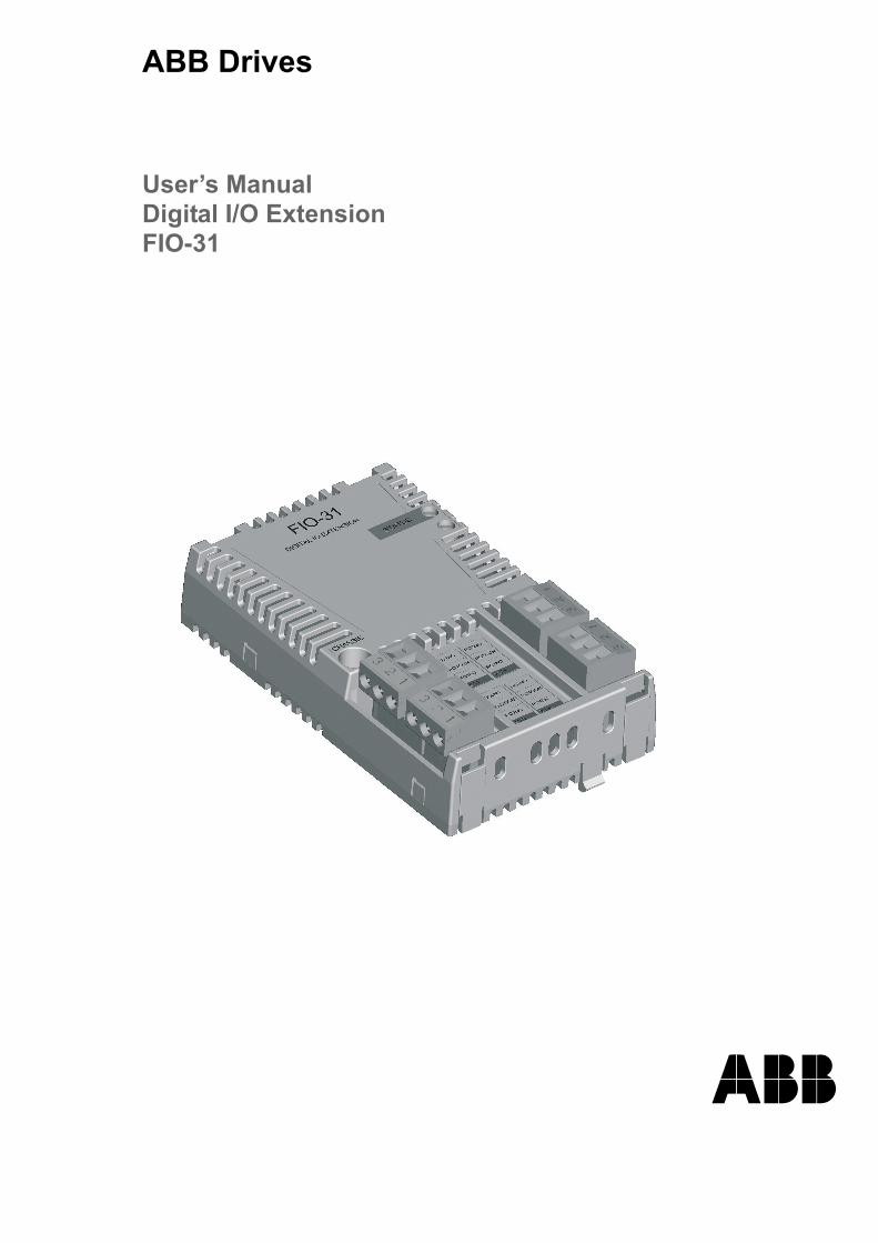
ABB Drives
User�s ManualDigital I/O ExtensionFIO-31

Digital I/O ExtensionFIO-31
User�s Manual
3AUA0000055162 Rev AEN
EFFECTIVE: 01.04.2009
© 2009 ABB Oy. All Rights Reserved.


5
Safety instructions
OverviewThis chapter states the general safety instructions that must be followed when installing and operating the FIO-31 Digital I/O Extension.
In addition to the safety instructions given below, read the complete safety instructions of the specific drive you are working on.
These warnings are intended for all who work on the drive. Ignoring the instructions can cause physical injury or death, or damage the equipment.
General safety instructions
WARNING! All electrical installation and maintenance work on the drive should be carried out by qualified electricians only.
The drive and adjoining equipment must be properly earthed.
Do not attempt any work on a powered drive. After switching off the mains, always allow the intermediate circuit capacitors to discharge for 5 minutes before working on the frequency converter, the motor or the motor cable. It is good practice to check (with a voltage indicating instrument) that the drive is in fact discharged before beginning work.
The motor cable terminals of the drive are at a dangerously high voltage when mains power is applied, regardless of motor operation.
There can be dangerous voltages inside the drive from external control circuits even when the drive mains power is shut off. Exercise appropriate care when working on the unit.
Safety instructions

6
Safety instructions

7
Table of contents
Safety instructions . . . . . . . . . . . . . . . . . . . . . . . . . . . . . . . . . . . . . . . . . . . . 5
Overview . . . . . . . . . . . . . . . . . . . . . . . . . . . . . . . . . . . . . . . . . . . . . . . . . . . . 5General safety instructions . . . . . . . . . . . . . . . . . . . . . . . . . . . . . . . . . . . . . . . 5
Table of contents . . . . . . . . . . . . . . . . . . . . . . . . . . . . . . . . . . . . . . . . . . . . . 7
Introduction . . . . . . . . . . . . . . . . . . . . . . . . . . . . . . . . . . . . . . . . . . . . . . . . . 9
Intended audience . . . . . . . . . . . . . . . . . . . . . . . . . . . . . . . . . . . . . . . . . . . . . 9Before you start . . . . . . . . . . . . . . . . . . . . . . . . . . . . . . . . . . . . . . . . . . . . . . . 9What this manual contains . . . . . . . . . . . . . . . . . . . . . . . . . . . . . . . . . . . . . . . 9Product and service inquiries . . . . . . . . . . . . . . . . . . . . . . . . . . . . . . . . . . . . 10Product training . . . . . . . . . . . . . . . . . . . . . . . . . . . . . . . . . . . . . . . . . . . . . . 10Providing feedback on ABB Drives manuals . . . . . . . . . . . . . . . . . . . . . . . . 10
Overview . . . . . . . . . . . . . . . . . . . . . . . . . . . . . . . . . . . . . . . . . . . . . . . . . . . 11
Overview . . . . . . . . . . . . . . . . . . . . . . . . . . . . . . . . . . . . . . . . . . . . . . . . . . . 11The FIO-31 Digital I/O Extension . . . . . . . . . . . . . . . . . . . . . . . . . . . . . . . . . 11
Installation . . . . . . . . . . . . . . . . . . . . . . . . . . . . . . . . . . . . . . . . . . . . . . . . . 13
Mounting . . . . . . . . . . . . . . . . . . . . . . . . . . . . . . . . . . . . . . . . . . . . . . . . . . . 13Terminal designations . . . . . . . . . . . . . . . . . . . . . . . . . . . . . . . . . . . . . . . . . 14Wiring . . . . . . . . . . . . . . . . . . . . . . . . . . . . . . . . . . . . . . . . . . . . . . . . . . . . . . 15Programming . . . . . . . . . . . . . . . . . . . . . . . . . . . . . . . . . . . . . . . . . . . . . . . . 15
Fault tracing . . . . . . . . . . . . . . . . . . . . . . . . . . . . . . . . . . . . . . . . . . . . . . . . 17
Diagnostic LEDs . . . . . . . . . . . . . . . . . . . . . . . . . . . . . . . . . . . . . . . . . . . . . . 17
Technical data . . . . . . . . . . . . . . . . . . . . . . . . . . . . . . . . . . . . . . . . . . . . . . 19
Table of contents

8
Table of contents

9
Introduction
Intended audienceThe manual is intended for the people who are responsible for commissioning and using the FIO-31 Digital I/O Extension. The reader is expected to have a basic knowledge of electrical fundamentals, electrical wiring practices and how to operate the drive.
Before you startIt is assumed that the drive is installed and the drive power supply is switched off before starting the installation of the extension module. Ensure that all dangerous voltages connected from external control circuits to the inputs and outputs of the drive are switched off.
In addition to conventional installation tools, have the drive manuals available during the installation as they contain important information not included in this manual. The drive manuals are referred to at various points of this document.
What this manual containsThis manual contains information on the wiring, configuration and use of the FIO-31 Digital I/O Extension.
Safety instructions are featured in the first few pages of this manual.
Overview contains a short description of the FIO-31.
Installation contains instructions for hardware settings, mounting and cabling.
Fault tracing explains LED indications.
Technical data contains detailed technical information.
Introduction
10
Product and service inquiriesAddress any inquiries about the product to your local ABB representative, quoting the type code and serial number of the unit in question. A listing of ABB sales, support and service contacts can be found by navigating to www.abb.com/drives and selecting Sales, Support and Service network.
Product trainingFor information on ABB product training, navigate to www.abb.com/drives and select Training courses.
Providing feedback on ABB Drives manualsYour comments on our manuals are welcome. Go to www.abb.com/drives and select Document Library � Manuals feedback form (LV AC drives).
Introduction

11
Overview
Overview This chapter contains a short description of the FIO-31 Digital I/O Extension.
The FIO-31 Digital I/O ExtensionThe FIO-31 is a general purpose relay extension. It offers four relay outputs.
FIO-31 layout
Diagnostic LED
Relay outputs
Fixing screw
Relay outputs
Overview

12
Isolation areasThe following figure describes the different isolation areas of the module.
The fixing screw connects the chassis to ground.
X104
X20
1
CHASSIS
Relay outputs
Fixing screw
Connection to the drive
X103
X102X101
Overview

13
Installation
WARNING! Follow the safety instructions given in this manual and in the drive Hardware Manual.
Mounting
WARNING! Before installation, switch off the drive power supply. Wait for five minutes to ensure that the capacitor bank of the drive is discharged. Switch off all dangerous voltages connected from external control circuits to the inputs and outputs of the drive.
The FIO-31 is to be inserted into the option slot of the drive. The module is held in place with plastic retaining clips and one screw. On installation of the module, the signal and power connection to the drive is automatically made through a 20-pin connector.
Mounting procedure:
� Insert the module carefully into the option slot until the retaining clips lock the module into position.
� Fasten the screw (included) to the stand-off.
Note: Correct installation of the screw is essential for fulfilling the EMC requirements and for proper operation of the module.
Installation sites above 2000 metres (6562 feet)The Protective Extra Low Voltage (PELV) requirements are not fulfilled when altitude is greater than 2000 m (6562 feet) and relays are used with voltage greater than 48 V.
Installation

14
Terminal designationsMarking Description
X101 Relay output� 240 V AC / 30 V DC, 2 A� NO = relay normally open� COM = common� NC = relay normally closed
1 RO1NO2 RO1COM3 RO1NCX1021 RO2NO2 RO2COM3 RO2NCX1031 RO3NO2 RO3COM3 RO3NCX1041 RO4NO2 RO4COM3 RO4NC
Installation

15
WiringMaximum 2.5 mm2 (AWG 14) cable should be used for the signals. The cable shields should be connected to the JCU Control Unit. See the drive Hardware Manual for more information.
Note: Do not route signal cables parallel to power (e.g. motor) cables.
Tightening torque is 0.5 N·m (4.4 lb·in) for the plugs.
ProgrammingThe communication between the module and the drive is activated by a drive parameter. See the drive Firmware Manual.
Installation

16
Installation

17
Fault tracing
Diagnostic LEDsColour Description
STAT
US
LED Green OK
Red Power fault & not initialized or communication fault to control unit
Fault tracing

18
Fault tracing

19
Technical data
Dimensions
General� Max. power consumption: 60 mA at 24 V, 250 mA at 3.3 V
� Degree of protection: IP20
� Ambient conditions: The applicable ambient conditions specified for the drive in its Hardware Manual are in effect.
Connectors� 20 pin socket
� 4 pcs. 3-pole detachable terminal plugs.
106
mm
32 mm1.26 in
2.48 in
4.17
in
0.91 in23 mm 63 mm
Technical data

20
Relay output� 240 V AC or 30 V DC, 2 A resistive load
� Varistors for inductive load protection.
Technical data


3AU
A00
0005
5162
Rev
A /
EN
EFF
EC
TIV
E: 0
1.04
.200
9
ABB OyAC DrivesP.O. Box 184FIN-00381 HELSINKIFINLANDTelephone +358 10 22 11Telefax +358 10 22 22681Internet www.abb.com
ABB Inc.Automation TechnologiesDrives & Motors16250 West Glendale DriveNew Berlin, WI 53151USATelephone 262 785-3200
800-HELP-365Telefax 262 780-5135
ABB Beijing Drive Systems Co. Ltd.No. 1, Block D, A-10 Jiuxianqiao BeiluChaoyang DistrictBeijing, P.R. China, 100015Telephone +86 10 5821 7788Fax +86 10 5821 7618