Embed Size (px)
Citation preview
European Telecommunications Standards Institute
EN 300 748 V1.1.2 (1997-08)European Standard (Telecommunications series)
Digital Video Broadcasting (DVB);Multipoint Video Distribution Systems (MVDS)
at 10 GHz and above
EBUUER
European Broadcasting Union Union Européenne de Radio-Télévision
EN 300 748 V1.1.2 (1997-08)2
ReferenceREN/JTC-00DVB-68 (6xc00idc.PDF)
KeywordsDVB, digital, video, broadcasting, MPEG, TV,
multipoint
ETSI Secretariat
Postal addressF-06921 Sophia Antipolis Cedex - FRANCE
Office address650 Route des Lucioles - Sophia Antipolis
Valbonne - FRANCETel.: +33 4 92 94 42 00 Fax: +33 4 93 65 47 16
Siret N° 348 623 562 00017 - NAF 742 CAssociation à but non lucratif enregistrée à laSous-Préfecture de Grasse (06) N° 7803/88
X.400c= fr; a=atlas; p=etsi; s=secretariat
[email protected]://www.etsi.fr
Copyright Notification
No part may be reproduced except as authorized by written permission.The copyright and the foregoing restriction extend to reproduction in all media.
© European Telecommunications Standards Institute 1997.© European Broadcasting Union 1997.
All rights reserved.
EN 300 748 V1.1.2 (1997-08)3
Contents
Intellectual Property Rights................................................................................................................................4
Foreword ............................................................................................................................................................4
1 Scope........................................................................................................................................................5
2 Normative references ...............................................................................................................................5
3 Symbols and abbreviations ......................................................................................................................63.1 Symbols ............................................................................................................................................................. 63.2 Abbreviations..................................................................................................................................................... 6
4 Transmission system................................................................................................................................74.1 System definition ............................................................................................................................................... 74.2 Adaptation to MVDS transmitter characteristics ............................................................................................... 84.3 Interfacing.......................................................................................................................................................... 84.4 Channel coding .................................................................................................................................................. 94.4.1 Transport multiplex adaptation and randomization for energy dispersal...................................................... 94.4.2 Outer coding (Reed-Solomon), interleaving and framing .......................................................................... 104.4.3 Inner coding (convolutional) ...................................................................................................................... 124.5 Baseband shaping and modulation................................................................................................................... 13
5 Error performance requirements ............................................................................................................14
Annex A (normative): Signal spectrum at the modulator output ...................................................15
Annex B (informative): Conceptual system description.....................................................................17
Annex C (informative): Examples of bit rates versus MVDS transmitter bandwidth ....................19
Annex D (informative): Examples of possible use of the System.......................................................20
Annex E (informative): Bibliography...................................................................................................21
History..............................................................................................................................................................22

EN 300 748 V1.1.2 (1997-08)4
Intellectual Property RightsIPRs essential or potentially essential to the present document may have been declared to ETSI. The informationpertaining to these essential IPRs, if any, is publicly available for ETSI members and non-members, and can be foundin ETR 314: "Intellectual Property Rights (IPRs); Essential, or potentially Essential, IPRs notified to ETSI in respect ofETSI standards", which is available free of charge from the ETSI Secretariat. Latest updates are available on the ETSIWeb server (http://www.etsi.fr/ipr).
Pursuant to the ETSI Interim IPR Policy, no investigation, including IPR searches, has been carried out by ETSI.No guarantee can be given as to the existence of other IPRs not referenced in ETR 314 (or the updates onhttp://www.etsi.fr/ipr) which are, or may be, or may become, essential to the present document.
ForewordThis second edition, previously as an ETS now an EN, contains changes of an entirely editorial nature as follows:
1) add the DVB logo to the front page of the deliverable;
2) change the title from: "Digital broadcasting systems for television, sound and data services; etc." to"Digital Video Broadcast (DVB); etc.";
3) add in the foreword the DVB acknowledgement.
This European Standard (Telecommunications series) has been produced by the Joint Technical Committee (JTC) of theEuropean Broadcasting Union (EBU), Comité Européen de Normalisation ELECtrotechnique (CENELEC) and theEuropean Telecommunications Standards Institute (ETSI).
NOTE: The EBU/ETSI JTC was established in 1990 to co-ordinate the drafting of standards in the specific fieldof broadcasting and related fields. Since 1995 the JTC became a tripartite body by including in theMemorandum of Understanding also CENELEC, which is responsible for the standardization of radio andtelevision receivers. The EBU is a professional association of broadcasting organizations whose workincludes the co-ordination of its members' activities in the technical, legal, programme-making andprogramme-exchange domains. The EBU has active members in about 60 countries in the Europeanbroadcasting area; its headquarters is in Geneva *.
* European Broadcasting Union
Case Postale 67
CH-1218 GRAND SACONNEX (Geneva)
Switzerland
Tel: +41 22 717 21 11
Fax: +41 22 717 24 81
Digital Video Broadcasting (DVB) Project
Founded in September 1993, the DVB Project is a market-led consortium of public and private sector organizations inthe television industry. Its aim is to establish the framework for the introduction of MPEG-2 based digital televisionservices. Now comprising over 200 organizations from more than 25 countries around the world, DVB fosters market-led systems, which meet the real needs, and economic circumstances, of the consumer electronics and the broadcastindustry.
Proposed national transposition dates
Date of adoption of this EN: 18 October 1996
Date of latest announcement of this EN (doa): 31 January 1997
Date of latest publication of new National Standardor endorsement of this EN (dop/e): 31 July 1997
Date of withdrawal of any conflicting National Standard (dow): 31 July 1997

EN 300 748 V1.1.2 (1997-08)5
1 ScopeThe present document describes the modulation and channel coding system (denoted the "System" for the purposes of thepresent document) for the distribution of digital multi-programme Television (TV) / High Definition Television (HDTV) byMultipoint Video Distribution Systems (MVDS) in the 40 GHz band. The System described in the present document isbased on that described in EN 300 421 for 11/12 GHz satellite services (see annex E, bibliography).It allows the same consumer Integrated Receiver Decoder (IRD) to be used for either service, when used with a Low NoiseBlock (LNB) down-converter for the appropriate frequency band.
The frequency band 40,5 to 42,5 GHz has been harmonized within the European Conference of Post andTelecommunications Administrations (CEPT) under Recommendation T/R 52-01.The System however, is applicable to other frequency bands above 10 GHz.
The System uses Quaternary Phase Shift Keying (QPSK) modulation and concatenated error protection strategy based on aconvolutional code and shortened Reed-Solomon (RS) code.
The System is suitable for use on different MVDS transmitter bandwidths.
Compatibility with Moving Pictures Experts Group - 2 (MPEG-2) coded TV services (see ISO/IEC 13818-1 [1]),with a transmission structure synchronous with the packet multiplex, is provided.Exploitation of the multiplex flexibility allows the use of the transmission capacity for a variety of TV serviceconfigurations, including sound and data services.All service components are Time Division Multiplexed (TDM) on a single digital carrier.
The present document:
- gives a general description of the System for MVDS digital TV transmission;
- specifies the digitally modulated signal in order to allow compatibility between pieces of equipment developed bydifferent manufacturers. This is achieved by describing in detail the signal processing principles at the modulatorside, while the processing at the receive side is left open to different implementation solutions. However, it isnecessary in the present document to refer to certain aspects of reception;
- identifies the global performance requirements and features of the System, in order to meet the service qualitytargets.
2 Normative referencesReferences may be made to:
a) specific versions of publications (identified by date of publication, edition number, version number, etc.), inwhich case, subsequent revisions to the referenced document do not apply; or
b) all versions up to and including the identified version (identified by "up to and including" before the versionidentity); or
c) all versions subsequent to and including the identified version (identified by "onwards" following the versionidentity); or
d) publications without mention of a specific version, in which case the latest version applies.
A non-specific reference to an ETS shall also be taken to refer to later versions published as an EN with the samenumber.
[1] ISO/IEC 13818-1 (November 1994): "Coding of moving pictures and associated audio".
[2] Forney, G.D. IEEE Trans. Comm. Tech., COM-19, pp. 772-781, (October 1971): "Burst-correcting codes for the classic bursty channel".
[3] Intelsat Earth Station Standards (IESS) No. 308, revision 6 (26 October 1990): "Performancecharacteristics for Intermediate Data Rate (IDR) digital carriers".
EN 300 748 V1.1.2 (1997-08)6
3 Symbols and abbreviations
3.1 SymbolsFor the purposes of the present document, the following symbols apply:
α roll-off factorC/N Signal-to-Noise ratiodfree convolutional code free distanceEb/N0 ratio between the energy per useful bit and twice the noise power spectral densityfN Nyquist frequencyG1,G2 convolutional code generatorsg(x) RS code generator polynomialI Interleaving depth (bytes)I, Q In-phase, Quadrature phase components of the modulated signalj branch index of the interleaverK convolutional code constraint lengthM convolutional interleaver branch depth for j = 1, M = N/IN error protected frame length (bytes)p(x) RS field generator polynomialrm in-band ripple (dB)Rs symbol Rate corresponding to the bilateral Nyquist bandwidth of the modulated signalRu useful bit Rate after MPEG-2 transport multiplexerRu' bit rate after RS outer coderT number of bytes which can be corrected in RS error protected packetTs symbol periodX,Y di-bit stream after rate 1/2 convolutional coding
3.2 AbbreviationsFor the purposes of the present document, the following abbreviations apply:
AWGN Additive White Gaussian NoiseBB BaseBandBER Bit Error RatioBSS Broadcast Satellite ServiceBW BandWidthCCITT International Telegraph and Telephone Consultative Committee (now ITU-T)DTH Direct To HomeFDM Frequency Division MultiplexFEC Forward Error CorrectionFIFO First-In, First-Out shift registerFIR Finite Impulse ResponseFSS Fixed Satellite ServiceHDTV High Definition TeleVisionHEX HEXadecimal notationIF Intermediate FrequencyIMUX Input MUltipleXer - filterIRD Integrated Receiver DecoderMPEG Moving Pictures Experts GroupMSB Most Significant BitMUX MUltipleXMVDS Multipoint Video Distribution SystemOBO Output Back OffOCT OCTal notationOMUX Output MUltipleXer - filterP PuncturingPDH Plesiochronous Digital Hierarchy

EN 300 748 V1.1.2 (1997-08)7
PRBS Pseudo Random Binary SequencePSK Phase Shift KeyingQEF Quasi-Error-FreeQPSK Quaternary PSKR Randomized sequenceRF Radio FrequencyRS Reed-SolomonSMATV Satellite Master Antenna TeleVisionTBD To Be DefinedTDM Time Division MultiplexTV TeleVisionTWTA Travelling Wave Tube Amplifier
4 Transmission system
4.1 System definitionThe System is defined as the functional block of equipment performing the adaptation of the baseband TV signals from theoutput of the MPEG-2 transport multiplexer, to the MVDS channel characteristics.The following processes shall be applied to the data stream (see figure 1):
- transport multiplex adaptation and randomization for energy dispersal;
- outer coding (i.e. Reed-Solomon);
- convolutional interleaving;
- inner coding (i.e. punctured convolutional code);
- baseband shaping for modulation;
- modulation.
The System functional description is given in annex B.
MVDS services at millimetric frequency bands are particularly affected by power limitations, therefore ruggedness againstnoise and interference shall be the main design objective, rather than spectrum efficiency.
To achieve a very high power efficiency without excessively penalizing the spectrum efficiency, the System shall use QPSKmodulation and the concatenation of convolutional and RS codes.
The convolutional code is able to be configured flexibly, allowing the optimization of the system performance for a givenMVDS transmitter bandwidth (see annex C).
The System is suitable for single carrier per MVDS transmitter Time Division Multiplex (TDM) type applications.
The System can also be used for multi-carrier Frequency Division Multiplex (FDM) type applications.

EN 300 748 V1.1.2 (1997-08)8
to the RFMVDSChannel
QPSKmodulator
MVDS channel adapter
Service components
MPEG - 2
Source coding and multiplexing
Services
Video coder
Audio coder
Data coder
1
2
n
MUX
adaptation&
energy
dispersal
Outer
coder
Conv.
inter-
leaver
Inner
coder
Baseband
shaping
RS (204, 188)Convolutional
code
Pro
gram
me
MU
X
Tran
spor
tM
UX
Figure 1: Functional block diagram of the System
The System is directly compatible with MPEG-2 coded TV signals. The modem transmission frame is synchronous withthe MPEG-2 multiplex transport packets.
If the received signal is above C/N and C/I threshold, the Forward Error Correction (FEC) technique adopted in theSystem is designed to provide a Quasi Error Free (QEF) quality target. The QEF means less than one uncorrectederror-event per transmission hour, corresponding to Bit Error Ratio (BER) = 10-10 to 10-11 at the input of the MPEG-2demultiplexer.
4.2 Adaptation to MVDS transmitter characteristicsMVDS transmitters of digital multi-programme TV services will use channels within band plans set according to individualcountries' planning and regulatory criteria and are required to provide compatibility with existing digital cable and satelliteservices. The MVDS transmitter performance specification and, in particular, its operating bandwidth will determine thedata rates available to the service.
The symbol rate shall be matched to given MVDS transmitter characteristics. Examples based on computer simulations fora hypothetical MVDS chain, not including interference effects, are given in annex C.
4.3 InterfacingThe System, as defined in the present document, shall be delimited by the following interfaces given in table 1:
Table 1: System interfaces
Location Interface Interface type ConnectionTransmit station Input MPEG-2
transport multiplexfrom MPEG-2
multiplexerOutput 70/140 MHz IF to RF devices
Receive installation Output MPEG-2transport multiplex
to MPEG-2demultiplexer
Input TBD from RF devices(indoor unit)

EN 300 748 V1.1.2 (1997-08)9
4.4 Channel coding
4.4.1 Transport multiplex adaptation and randomization for energydispersal
The System input stream shall be organized in fixed length packets (see figure 3), following the MPEG-2 transportmultiplexer. The total packet length of the MPEG-2 transport Multiplex (MUX) packet is 188 bytes.This includes 1 sync-word byte (i.e. 47HEX). The processing order at the transmitting side shall always start from theMSB (i.e. "0") of the sync word-byte (i.e. 01000111).
In order to comply with ITU Radio Regulations and to ensure adequate binary transitions, the data of the input MPEG-2multiplex shall be randomized in accordance with the configuration depicted in figure 2.
The polynomial for the Pseudo Random Binary Sequence (PRBS) generator shall be:
1 + X14 + X15 .
Loading of the sequence "100101010000000" into the PRBS registers, as indicated in figure 2, shall be initiated at thestart of every eight transport packets. To provide an initialization signal for the descrambler, the MPEG-2 sync byte ofthe first transport packet in a group of eight packets is bit-wise inverted from 47HEX to B8HEX. This process is referredto as the "Transport Multiplex Adaptation".
The first bit at the output of the PRBS generator shall be applied to the first bit (i.e. MSB) of the first byte following theinverted MPEG-2 sync byte (i.e. B8HEX). To aid other synchronization functions, during the MPEG-2 sync bytes of thesubsequent 7 transport packets, the PRBS generation shall continue, but its output shall be disabled, leaving these bytesunrandomized. Thus, the period of the PRBS sequence shall be 1 503 bytes.
The randomization process shall be active also when the modulator input bit-stream is non-existent, or when it is non-compliant with the MPEG-2 transport stream format (i.e. 1 sync byte + 187 packet bytes). This is to avoid the emissionof an unmodulated carrier from the modulator.
E n a b le C le a r / r a n d o m iz e d
d a ta i n p u t
R a n d o m iz e d / d e - r a n d o m iz e d
d a t a o u t p u t
I n i t i a l i z a t i o n s e q u e n c e
1 2 3 4 5 6 7 8 9 10 11 12 13 14 15
EX-ORAND
1 1 1 10 0 0 0 0 0 0 0 0 0 0
EX-OR0 0 0 0 0 0 1 1 . . . .
....
....x1
x1
x0
x0
x0
x0
x0
x0
Data input (MSB first): PRBS sequence :
1 0 1 1 1 0 0 0
Figure 2: Randomizer/de-randomizer schematic diagram

EN 300 748 V1.1.2 (1997-08)10
4.4.2 Outer coding (Reed-Solomon), interleaving and framing
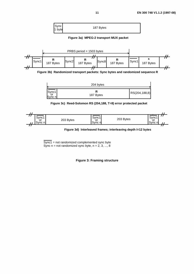
The framing organization shall be based on the input packet structure (see figure 3a).
Reed-Solomon RS(204,188, T = 8) shortened code, from the original RS(255,239, T = 8) code, shall be applied to eachrandomized transport packet (188 bytes) of figure 3b to generate an error protected packet (see figure 3c).
RS coding shall also be applied to the packet sync byte, either non-inverted (i.e. 47HEX) or inverted (i.e. B8HEX).
Code generator polynomial: g(x) = (x+λ0)(x+λ1)(x+λ2) ...(x+λ15), where λ = 02HEX.
Field generator polynomial: p(x) = x8 + x4 + x3 + x2 + 1.
The shortened RS code may be implemented by adding 51 bytes, all set to zero, before the information bytes at the inputof a (255,239) encoder.
After the RS coding procedure these null bytes shall be discarded.
Following the conceptual scheme of figure 4, convolutional interleaving with depth I = 12 shall be applied to the errorprotected packets (see figure 3c). This results in an interleaved frame (see figure 3d).
The convolutional interleaving process shall be based on the Forney approach [2] which is compatible with theRamsey type III approach, with I = 12.
The interleaved frame shall be composed of overlapping error protected packets and shall be delimited by inverted ornon-inverted MPEG-2 sync bytes (preserving the periodicity of 204 bytes).
The interleaver may be composed of I = 12 branches, cyclically connected to the input byte-stream by the input switch.
Each branch shall be a First-In, First-Out (FIFO) shift register, with depth (M j) cells(where M = 17 = N/I, N = 204 = error protected frame length, I = 12 = interleaving depth, j = branch index).
The cells of the FIFO shall contain 1 byte, and the input and output switches shall be synchronized.
For synchronization purposes, the sync bytes and the inverted sync bytes shall be always routed in the branch "0" of theinterleaver (corresponding to a null delay).
NOTE: The de-interleaver is similar, in principle, to the interleaver, but the branch indexes are reversed(i.e. j = 0 corresponds to the largest delay).The de-interleaver synchronization can be carried out by routeing the first recognized sync byte in the "0"branch.
EN 300 748 V1.1.2 (1997-08)11
Sync1 byte 187 Bytes
187 Bytes 187 Bytes 187 Bytes 187 BytesSync1 Sync2 Sync8 Sync1
RS(204,188,8)187 Bytes
Figure 3a) MPEG-2 transport MUX packet
204 bytes
Figure 3b) Randomized transport packets: Sync bytes and randomized sequence R
R R R R
Sync1 = not randomized complemented sync byteSync n = not randomized sync byte, n = 2, 3, ..., 8
Figure 3c) Reed-Solomon RS (204,188, T=8) error protected packet
R
Figure 3d) Interleaved frames; interleaving depth I=12 bytes
203 Bytes 203 Bytes
PRBS period = 1503 bytes
Sync1or
Sync n
Sync1or
Sync n
Sync1or
Sync n
Sync1or
Sync n
Figure 3: Framing structure

EN 300 748 V1.1.2 (1997-08)12
4.4.3 Inner coding (convolutional)
The System shall allow for a range of punctured convolutional codes, based on a rate 1/2 convolutional code withconstraint length K = 7.
This will allow selection of the most appropriate level of error correction for a given service or data rate.
The System shall allow convolutional coding with code rates of 1/2, 2/3, 3/4, 5/6 and 7/8.
The punctured convolutional code shall be used as given in table 2. See also figure 5.
NOTE: At the receiver, each of the code rates and puncturing configurations is in a position to be tried until lockis acquired. π phase ambiguity in the demodulator is able to be resolved by decoding the MPEG-2 syncbyte delimiting the interleaved frame.
0 1
2
3
11
01
2
3
11 = I -111 = I-1
0
10
9
8
11
0
10
9
81 byte per
position1 byte per
position
Sync word routeSync word route
17=M
17 x 2
17 x 3
17 x 11
FIFO shift register
Interleaver I = 12 De-interleaver I = 12
17 x 11
17 x 3
17 x 2
Figure 4: Conceptual diagram of the convolutional interleaver and de-interleaver
Table 2: Punctured code definition
Original code Code rates1/2 2/3 3/4 5/6 7/8
K
G1(X)
G2(Y)
P dfree P dfree P dfree P dfree P dfree
7 171OCT
133OCT
X: 1
Y: 1
I = X1
Q = Y1
10
X: 1 0
Y: 1 1
I = X1 Y2 Y3
Q = Y1 X3 Y4
6
X: 1 0 1
Y: 1 1 0
I = X1 Y2
Q = Y1 X3
5
X: 1 0 1 0 1
Y: 1 1 0 1 0
I = X1 Y2 Y4
Q = Y1 X3 X5
4
X: 1 0 0 0 1 0 1
Y: 1 1 1 1 0 1 0
I = X1 Y2 Y4 Y6
Q = Y1 Y3 X5 X7
3
NOTE: 1 = transmitted bit0 = non-transmitted bit

EN 300 748 V1.1.2 (1997-08)13
4.5 Baseband shaping and modulationThe System shall employ conventional Gray-coded QPSK modulation with absolute mapping (no differential coding).Bit mapping in the signal space as given on figure 5 shall be used.
Prior to modulation, the I and Q signals (mathematically represented by a succession of Dirac delta functions spaced bythe symbol duration Ts = 1/Rs, with appropriate sign) shall be square root raised cosine filtered.
The roll-off factor α shall be 0,35.
436.
VHULDO
ELW�VWUHDP
X
Y
I
Q
%DVHEDQG
6KDSLQJ 0RGXODWRU3XQFWXULQJ
(QFRGHU
&RQYROXWLRQDO
Q
I
10
I =Q =
00
I =Q =
01
I =Q =
11
I =Q =
Figure 5: QPSK constellation
The baseband square root raised cosine filter shall have a theoretical function defined by the following expression:
H(f) = 1 for f < ( )f N 1− α
H(f) =
1
2
1
2 2
12
+
−sin
παf N
fN
f
for ( )f N 1− α ≤ f ≤ ( )f N 1+ α
H(f) = 0 for f > ( )f N 1+ α ,
where
fT
RN
s
s= =1
2 2is the Nyquist frequency
and
α is the roll-off factor, α = 0,35.
A template for the signal spectrum at the modulator output is given in annex A.

EN 300 748 V1.1.2 (1997-08)14
5 Error performance requirementsThe modem, connected in the IF loop, shall meet the BER versus Eb/No performance requirements given in table 3.
Table 3: IF-loop performance of the System
Inner code rateRequired E b/No for
BER = 2 × 10⁻⁴ after ViterbiQEF after Reed-Solomon
1/2 4,5
2/3 5,0
3/4 5,5
5/6 6,0
7/8 6,4
NOTE 1: The figures of Eb/No refer to the useful bit-rate before RS coding and include amodem implementation margin of 0,8 dB and the noise bandwidth increase due tothe outer code (10 log 188/204 = 0,36 dB).
NOTE 2: Quasi-Error-Free (QEF) means less than one uncorrected error event per hour,corresponding to BER = 10-10 to 10-11 at the input of the MPEG-2 demultiplexer.
Indicative figures of the System performance by MVDS are given in annex D.
EN 300 748 V1.1.2 (1997-08)15
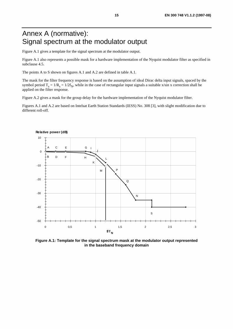
Annex A (normative):Signal spectrum at the modulator outputFigure A.1 gives a template for the signal spectrum at the modulator output.
Figure A.1 also represents a possible mask for a hardware implementation of the Nyquist modulator filter as specified insubclause 4.5.
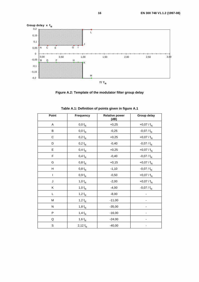
The points A to S shown on figures A.1 and A.2 are defined in table A.1.
The mask for the filter frequency response is based on the assumption of ideal Dirac delta input signals, spaced by thesymbol period Ts = 1/Rs = 1/2fN, while in the case of rectangular input signals a suitable x/sin x correction shall beapplied on the filter response.
Figure A.2 gives a mask for the group delay for the hardware implementation of the Nyquist modulator filter.
Figures A.1 and A.2 are based on Intelsat Earth Station Standards (IESS) No. 308 [3], with slight modification due todifferent roll-off.
Relative power (dB)
-50
-40
-30
-20
-10
0
10
0 0,5 1 1,5 2 2,5 3
A
B
C
D
E
F
G
H
J
KL
M
N
P
Q
S
I
f/f N
Figure A.1: Template for the signal spectrum mask at the modulator output representedin the baseband frequency domain
EN 300 748 V1.1.2 (1997-08)16
f / f-0,2
-0,15
-0,1
-0,05
0
0,05
0,1
0,15
0,2
0,00 0,50 1,00 1,50 2,00 2,50 3,00
N
Group delay x f N
A
B
C
D
E
F
G
H
IJ
K
L
M
Figure A.2: Template of the modulator filter group delay
Table A.1: Definition of points given in figure A.1
Point Frequency Relative power(dB)
Group delay
A 0,0 fN +0,25 +0,07 / fN
B 0,0 fN -0,25 -0,07 / fN
C 0,2 fN +0,25 +0,07 / fN
D 0,2 fN -0,40 -0,07 / fN
E 0,4 fN +0,25 +0,07 / fN
F 0,4 fN -0,40 -0,07 / fN
G 0,8 fN +0,15 +0,07 / fN
H 0,8 fN -1,10 -0,07 / fN
I 0,9 fN -0,50 +0,07 / fN
J 1,0 fN -2,00 +0,07 / fN
K 1,0 fN -4,00 -0,07 / fN
L 1,2 fN -8,00 -
M 1,2 fN -11,00 -
N 1,8 fN -35,00 -
P 1,4 fN -16,00 -
Q 1,6 fN -24,00 -
S 2,12 fN -40,00 -
EN 300 748 V1.1.2 (1997-08)17
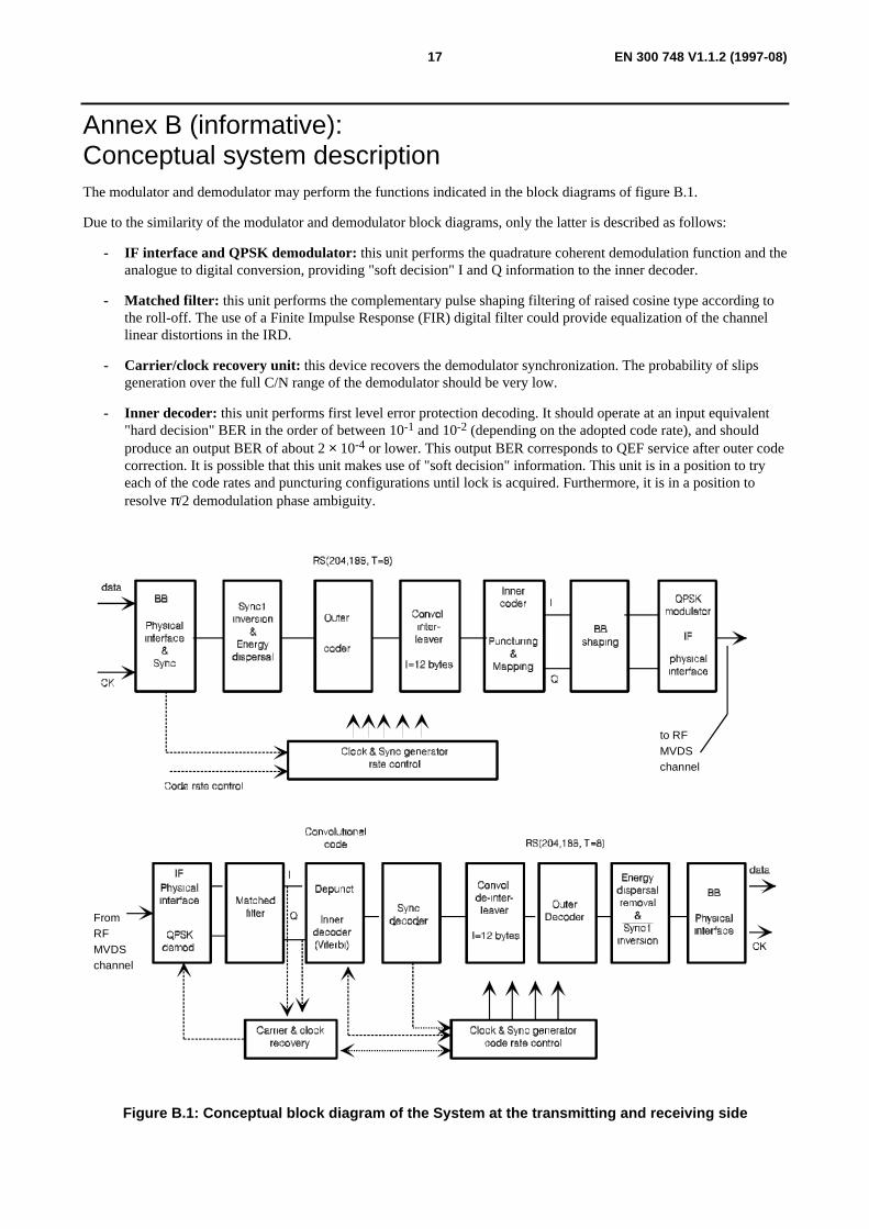
Annex B (informative):Conceptual system descriptionThe modulator and demodulator may perform the functions indicated in the block diagrams of figure B.1.
Due to the similarity of the modulator and demodulator block diagrams, only the latter is described as follows:
- IF interface and QPSK demodulator: this unit performs the quadrature coherent demodulation function and theanalogue to digital conversion, providing "soft decision" I and Q information to the inner decoder.
- Matched filter: this unit performs the complementary pulse shaping filtering of raised cosine type according tothe roll-off. The use of a Finite Impulse Response (FIR) digital filter could provide equalization of the channellinear distortions in the IRD.
- Carrier/clock recovery unit: this device recovers the demodulator synchronization. The probability of slipsgeneration over the full C/N range of the demodulator should be very low.
- Inner decoder: this unit performs first level error protection decoding. It should operate at an input equivalent"hard decision" BER in the order of between 10-1 and 10-2 (depending on the adopted code rate), and shouldproduce an output BER of about 2 × 10⁻⁴ or lower. This output BER corresponds to QEF service after outer codecorrection. It is possible that this unit makes use of "soft decision" information. This unit is in a position to tryeach of the code rates and puncturing configurations until lock is acquired. Furthermore, it is in a position toresolve π/2 demodulation phase ambiguity.
to RFMVDSchannel
FromRFMVDSchannel
Figure B.1: Conceptual block diagram of the System at the transmitting and receiving side

EN 300 748 V1.1.2 (1997-08)18
- Sync byte decoder: by decoding the MPEG-2 sync bytes, this decoder provides synchronization information forthe de-interleaving. It is also in a position to recover π ambiguity of QPSK demodulator (not detectable by theViterbi decoder).
- Convolutional de-interleaver: this device allows the error bursts at the output of the inner decoder to berandomized on a byte basis in order to improve the burst error correction capability of the outer decoder.
- Outer decoder: this unit provides second level error protection. It is in a position to provide QEF output(i.e. BER of about 10-10 to 10-11) in the presence of input error bursts at a BER of about 7 × 10⁻⁴ or better withinfinite byte interleaving. In the case of interleaving depth I = 12, BER = 2 × 10⁻⁴ is assumed for QEF.
- Energy dispersal removal: this unit recovers the user data by removing the randomizing pattern used for energydispersal purposes and changes the inverted sync byte to its normal MPEG-2 sync byte value.
- Baseband physical interface: this unit adapts the data structure to the format and protocol required by theexternal interface.
NOTE: A possibility is provided by the MPEG-2 system to set on the error flag bit in the packet header if thecorrection capability of the outer code is exceeded.
EN 300 748 V1.1.2 (1997-08)19
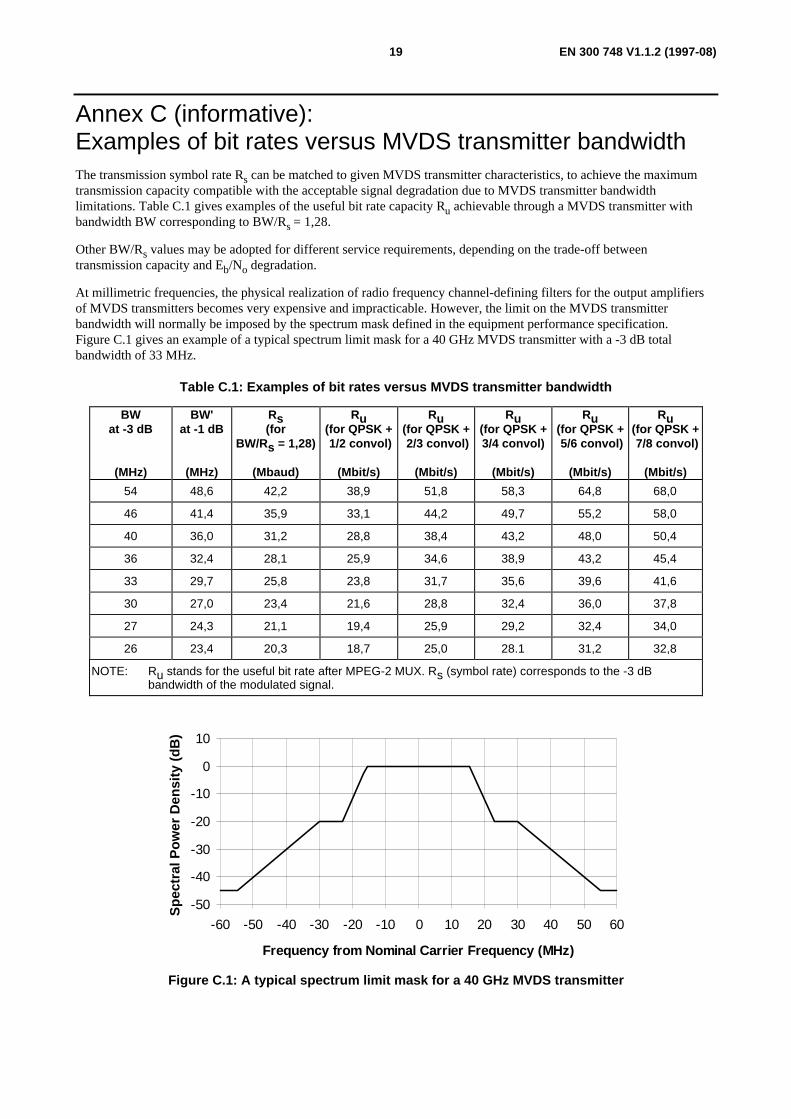
Annex C (informative):Examples of bit rates versus MVDS transmitter bandwidthThe transmission symbol rate Rs can be matched to given MVDS transmitter characteristics, to achieve the maximumtransmission capacity compatible with the acceptable signal degradation due to MVDS transmitter bandwidthlimitations. Table C.1 gives examples of the useful bit rate capacity Ru achievable through a MVDS transmitter withbandwidth BW corresponding to BW/Rs = 1,28.
Other BW/Rs values may be adopted for different service requirements, depending on the trade-off betweentransmission capacity and Eb/No degradation.
At millimetric frequencies, the physical realization of radio frequency channel-defining filters for the output amplifiersof MVDS transmitters becomes very expensive and impracticable. However, the limit on the MVDS transmitterbandwidth will normally be imposed by the spectrum mask defined in the equipment performance specification.Figure C.1 gives an example of a typical spectrum limit mask for a 40 GHz MVDS transmitter with a -3 dB totalbandwidth of 33 MHz.
Table C.1: Examples of bit rates versus MVDS transmitter bandwidth
BWat -3 dB
(MHz)
BW'at -1 dB
(MHz)
Rs(for
BW/Rs = 1,28)
(Mbaud)
Ru(for QPSK + 1/2 convol)
(Mbit/s)
Ru(for QPSK + 2/3 convol)
(Mbit/s)
Ru(for QPSK +3/4 convol)
(Mbit/s)
Ru(for QPSK + 5/6 convol)
(Mbit/s)
Ru(for QPSK + 7/8 convol)
(Mbit/s)
54 48,6 42,2 38,9 51,8 58,3 64,8 68,0
46 41,4 35,9 33,1 44,2 49,7 55,2 58,0
40 36,0 31,2 28,8 38,4 43,2 48,0 50,4
36 32,4 28,1 25,9 34,6 38,9 43,2 45,4
33 29,7 25,8 23,8 31,7 35,6 39,6 41,6
30 27,0 23,4 21,6 28,8 32,4 36,0 37,8
27 24,3 21,1 19,4 25,9 29,2 32,4 34,0
26 23,4 20,3 18,7 25,0 28.1 31,2 32,8
NOTE: Ru stands for the useful bit rate after MPEG-2 MUX. Rs (symbol rate) corresponds to the -3 dBbandwidth of the modulated signal.
-50
-40
-30
-20
-10
0
10
-60 -50 -40 -30 -20 -10 0 10 20 30 40 50 60
Frequency from Nominal Carrier Frequency (MHz)
Spe
ctra
l Pow
er D
ensi
ty (
dB)
Figure C.1: A typical spectrum limit mask for a 40 GHz MVDS transmitter

EN 300 748 V1.1.2 (1997-08)20
Annex D (informative):Examples of possible use of the SystemTable D.1 considers possible examples of use of the System for a nominal MVDS transmitter bandwidth (-3 dB) of33 MHz. Different inner code rates are given with the relevant bit rates.
Figure D.1 shows that the example highlighted in table D.1 with rate 2/3 inner code would be suitable for connection toa PDH terrestrial network at 34,368 Mbit/s, including the same RS error protection used by MVDS.
Table D.1: Example of System performance over 33 MHz MVDS transmitter
Bit rate R u(after MUX)
(Mbit/s)
Bit rate R' u(after RS)(Mbit/s)
Symbol rate
(Mbaud)
ConvolutionalInner
Code rate
RSOuter
Code rate
C/N(33 MHz)
(dB)
23,754 25,776 25,776 1/2 188/204 4,1
31,672 34,368 25,776 2/3 188/204 5,8
35,631 38,664 25,776 3/4 188/204 6,8
39,590 42,960 25,776 5/6 188/204 7,8
41,570 45,108 25,776 7/8 188/204 8,4
NOTE 1: The figures in table D.1 refer to computer simulation results achieved on a hypotheticalMVDS transmitter chain, conforming to the spectrum mask in figure C.1, with modulationroll-off of 0,35. The C/N figures are based on the assumption of soft-decision Viterbidecoding in the receiver. The ratio BW/Rs = 1,28 has been adopted.
NOTE 2: The figures for C/N include a calculated degradation of 0,8 dB non-linear distortion on theMVDS transmitter power amplifier (at saturation) and 0,8 dB modem degradation.The figures apply to BER = 2 × 10⁻⁴ before RS(204,188), which corresponds toQuasi Error Free (QEF) at the RS coder output. Degradation due to interference is nottaken into account.
Video Coder
Audio Coder
Data Coder Modulator
to the RFMVDS Channel
MVDS Channel AdaptationMPEG-2: Source Coding and Multiplexing
Transport
MUX
1
2
n
Service components Services
Convolutional
Outer
Coder
RS(204,188,T=8)
Inter-leaver
InnerCoder
rate 2/3
QPSK
TerrestrialNetwork
PDHBlockCoder
RS(204,188)
34,368 Mbit/s
BlockDecoder
Terrestrial Channel Adaptation
31,672 Mbit/sRu=
34,368 Mbit/sR'u=
(CCITT G702)
Convol.
I=12 K=7
& Interl.
RS(204,188)
& Deint.(Hier.Level III)
Figure D.1: Example of connection of the System with the terrestrial PDH network
EN 300 748 V1.1.2 (1997-08)21
Annex E (informative):BibliographyFor the purposes of the present document, the following informative references apply:
- TVB 1163/GT V4/MOD 269 2nd revised version (November 1993): "Potential applications of the baselinemodulation/channel coding system for digital multi-programme television by satellite" (Contribution fromV4/MOD).
- Reimers, U. NAB'93, (EBU V4/MOD 249): "The European perspectives on Digital Television Broadcasting".
- Cominetti, M., Morello, A., Visintin; M. EBU Review - Technical, Summer '93, (EBU V4/MOD 235 rev.):"Satellite digital multi-programme TV/HDTV".
- EN 300 421: "Digital Video Broadcasting (DVB); Framing structure, channel coding and modulation for11/12 GHz satellite services".
- EN 300 429: "Digital Video Broadcasting (DVB); Framing structure, channel coding and modulation for cablesystems".

EN 300 748 V1.1.2 (1997-08)22
History
Document history
Edition 1 October 1996 Publication as ETS 300 748
V1.1.2 August 1997 Publication
ISBN 2-7437-1676-2Dépôt légal : Août 1997


![TS 101 329-5 - V1.1.2 - Telecommunications and Internet Protocol … · 2002. 1. 11. · [30] ANSI T1A1.7/98-031: "Testing the quality of connections having time varying impairments"](https://img.dokumen.tips/doc/110x75/60ac52d5b084a7368c52e66e/ts-101-329-5-v112-telecommunications-and-internet-protocol-2002-1-11.jpg)