Embed Size (px)
Citation preview
ETSI EN 300 224-1 V1.3.1 (2001-01)European Standard (Telecommunications series)
Electromagnetic compatibilityand Radio spectrum Matters (ERM);
On-site paging service;Part 1: Technical and functional characteristics,
including test methods
ETSI
ETSI EN 300 224-1 V1.3.1 (2001-01)2
ReferenceREN/ERM-RP08-0110-1
Keywordspaging, radio, testing
ETSI
650 Route des LuciolesF-06921 Sophia Antipolis Cedex - FRANCE
Tel.: +33 4 92 94 42 00 Fax: +33 4 93 65 47 16
Siret N° 348 623 562 00017 - NAF 742 CAssociation à but non lucratif enregistrée à laSous-Préfecture de Grasse (06) N° 7803/88
Important notice
Individual copies of the present document can be downloaded from:http://www.etsi.org
The present document may be made available in more than one electronic version or in print. In any case of existing orperceived difference in contents between such versions, the reference version is the Portable Document Format (PDF).
In case of dispute, the reference shall be the printing on ETSI printers of the PDF version kept on a specific network drivewithin ETSI Secretariat.
Users of the present document should be aware that the document may be subject to revision or change of status.Information on the current status of this and other ETSI documents is available at http://www.etsi.org/tb/status/
If you find errors in the present document, send your comment to:[email protected]
Copyright Notification
No part may be reproduced except as authorized by written permission.The copyright and the foregoing restriction extend to reproduction in all media.
© European Telecommunications Standards Institute 2000.All rights reserved.

ETSI
ETSI EN 300 224-1 V1.3.1 (2001-01)3
Contents
Intellectual Property Rights ..........................................................................................................................7
Foreword......................................................................................................................................................7
1 Scope..................................................................................................................................................8
2 References ..........................................................................................................................................8
3 Definitions and abbreviations..............................................................................................................93.1 Definitions .................................................................................................................................................. 93.2 Abbreviations.............................................................................................................................................. 9
4 General...............................................................................................................................................94.1 Presentation of equipment for testing purposes............................................................................................. 94.2 Controls .................................................................................................................................................... 104.3 Modulation................................................................................................................................................ 104.4 Interpretation of the measurement results................................................................................................... 10
5 Test conditions, power sources and ambient temperatures .................................................................105.1 Normal and extreme test conditions ........................................................................................................... 105.2 Normal operational test conditions............................................................................................................. 105.2.1 Normal temperature and humidity ........................................................................................................ 105.2.2 Normal test power source..................................................................................................................... 105.3 Extreme test conditions.............................................................................................................................. 115.3.1 Procedure for tests at extreme temperatures .......................................................................................... 115.3.2 Extreme temperature limits .................................................................................................................. 125.3.3 Extreme test power source.................................................................................................................... 125.3.4 Test power source ................................................................................................................................ 12
6 Electrical test conditions ...................................................................................................................136.1 Normal test signals and test modulation ..................................................................................................... 136.1.1 Normal test signals for analogue speech ............................................................................................... 136.1.2 Normal test signals for data .................................................................................................................. 136.2 Artificial load............................................................................................................................................ 136.3 Test fixture for transmitters with an integral antenna .................................................................................. 136.4 Test site and general arrangement for measurements involving the use of radiated fields............................. 14
7 Transmitter .......................................................................................................................................147.1 Frequency error ......................................................................................................................................... 147.1.1 Definition ............................................................................................................................................ 147.1.2 Method of measurement....................................................................................................................... 157.1.3 Limits.................................................................................................................................................. 157.2 Carrier power ............................................................................................................................................ 157.2.1 Definition ............................................................................................................................................ 157.2.2 Carrier power (conducted).................................................................................................................... 167.2.2.1 Method of measurement.................................................................................................................. 167.2.2.2 Limits............................................................................................................................................. 167.2.3 Effective radiated power ...................................................................................................................... 167.2.3.1 Method of measurement.................................................................................................................. 167.2.3.2 Limits............................................................................................................................................. 187.3 Adjacent channel power ............................................................................................................................ 197.3.1 Definition ............................................................................................................................................ 197.3.2 Method of measurement....................................................................................................................... 197.3.3 Limits.................................................................................................................................................. 207.4 Frequency deviation .................................................................................................................................. 207.4.1 Definition ............................................................................................................................................ 207.4.2 Method of measurement....................................................................................................................... 217.4.3 Analogue signals within the audio bandwidth ....................................................................................... 217.4.3.1 Method of measurement.................................................................................................................. 217.4.3.2 Limits............................................................................................................................................. 21
ETSI
ETSI EN 300 224-1 V1.3.1 (2001-01)4
7.4.4 Analogue signals above the audio bandwidth........................................................................................ 217.4.4.1 Method of measurement.................................................................................................................. 217.4.4.2 Limits............................................................................................................................................. 227.5 Spurious emissions.................................................................................................................................... 227.5.1 Definition ............................................................................................................................................ 227.5.2 Method of measurement....................................................................................................................... 237.5.2.1 Method of measuring the spurious conducted power level ............................................................... 237.5.2.2 Method of measuring the effective radiated spurious power level..................................................... 237.5.3 Limits.................................................................................................................................................. 247.6 Transmitter transient behaviour.................................................................................................................. 247.6.1 Definition ............................................................................................................................................ 247.6.1.1 Keying criteria when the transmitter output power is switched on .................................................... 257.6.1.2 Keying criteria when the transmitter output power is switched off ................................................... 257.6.2 Method of measurement....................................................................................................................... 267.6.3 Limits.................................................................................................................................................. 27
8 Receiver requirements ......................................................................................................................278.1 Pocket paging receivers ............................................................................................................................. 278.1.1 Spurious emissions............................................................................................................................... 278.1.1.1 Definition ....................................................................................................................................... 278.1.1.2 Method of measurement.................................................................................................................. 278.1.1.3 Limits............................................................................................................................................. 288.2 Base station receivers ................................................................................................................................ 288.2.1 Measured sensitivity for analogue speech ............................................................................................. 288.2.1.1 Definition ....................................................................................................................................... 288.2.1.2 Method of measurement.................................................................................................................. 288.2.1.3 Limits............................................................................................................................................. 288.2.2 Measured sensitivity for messages........................................................................................................ 288.2.2.1 Definition ....................................................................................................................................... 288.2.2.2 Method of measurement.................................................................................................................. 288.2.2.3 Limits............................................................................................................................................. 298.2.3 Co-channel rejection for analogue speech ............................................................................................. 298.2.3.1 Definition ....................................................................................................................................... 298.2.3.2 Method of measurement.................................................................................................................. 298.2.3.3 Limits............................................................................................................................................. 298.2.4 Co-channel rejection for messages........................................................................................................ 298.2.4.1 Definition ....................................................................................................................................... 298.2.4.2 Method of measurement.................................................................................................................. 308.2.4.3 Limits............................................................................................................................................. 308.2.5 Adjacent channel selectivity for analogue speech.................................................................................. 308.2.5.1 Definition ....................................................................................................................................... 308.2.5.2 Method of measurement.................................................................................................................. 308.2.5.3 Limits............................................................................................................................................. 318.2.6 Adjacent channel selectivity for messages ............................................................................................ 318.2.6.1 Definition ....................................................................................................................................... 318.2.6.2 Method of measurement.................................................................................................................. 318.2.6.3 Limits............................................................................................................................................. 328.2.7 Spurious response immunity for analogue speech ................................................................................. 328.2.7.1 Definition ....................................................................................................................................... 328.2.7.2 Method of measurement.................................................................................................................. 328.2.7.3 Limit .............................................................................................................................................. 328.2.8 Spurious response immunity for messages............................................................................................ 328.2.8.1 Definition ....................................................................................................................................... 328.2.8.2 Method of measurement.................................................................................................................. 338.2.8.3 Limit .............................................................................................................................................. 338.2.9 Intermodulation immunity for analogue speech..................................................................................... 338.2.9.1 Definition ....................................................................................................................................... 338.2.9.2 Method of measurement.................................................................................................................. 348.2.9.3 Limit .............................................................................................................................................. 348.2.10 Intermodulation immunity for messages ............................................................................................... 348.2.10.1 Definition ....................................................................................................................................... 348.2.10.2 Method of measurement.................................................................................................................. 35
ETSI
ETSI EN 300 224-1 V1.3.1 (2001-01)5
8.2.10.3 Limit .............................................................................................................................................. 358.2.11 Blocking immunity or desensitization for analogue speech.................................................................... 368.2.11.1 Definition ....................................................................................................................................... 368.2.11.2 Method of measurement.................................................................................................................. 368.2.11.3 Limit .............................................................................................................................................. 368.2.12 Blocking immunity or desensitization for messages .............................................................................. 368.2.12.1 Definition ....................................................................................................................................... 368.2.12.2 Method of measurement.................................................................................................................. 378.2.12.3 Limit .............................................................................................................................................. 378.2.13 Spurious emissions............................................................................................................................... 378.2.13.1 Definition ....................................................................................................................................... 378.2.13.2 Method of measurement.................................................................................................................. 378.2.13.2.1 Conducted spurious components................................................................................................ 378.2.13.2.2 Radiated spurious components................................................................................................... 388.2.13.3 Limits............................................................................................................................................. 38
9 Inductive loop systems......................................................................................................................389.1 Additional definitions for inductive systems............................................................................................... 389.2 Loop transmitter requirements ................................................................................................................... 389.2.1 Transmitter carrier power ..................................................................................................................... 389.2.1.1 Definition ....................................................................................................................................... 389.2.1.2 Measuring method .......................................................................................................................... 389.2.1.3 Limit .............................................................................................................................................. 399.2.2 Range of operating frequencies ............................................................................................................ 399.2.2.1 Limits............................................................................................................................................. 399.2.2.2 Frequency error .............................................................................................................................. 399.2.2.2.1 Definition.................................................................................................................................. 399.2.2.2.2 Measuring method..................................................................................................................... 399.2.2.2.3 Limits ....................................................................................................................................... 399.2.2.3 Modulation bandwidth.................................................................................................................... 399.2.2.3.1 Definition.................................................................................................................................. 399.2.2.3.2 Measuring method..................................................................................................................... 409.2.2.3.3 Limit......................................................................................................................................... 409.2.3 Spurious emissions............................................................................................................................... 409.2.3.1 Definition ....................................................................................................................................... 409.2.3.2 Measuring methods......................................................................................................................... 409.2.3.2.1 Method of measuring the power level ........................................................................................ 409.2.3.2.2 Method of measuring the field strength...................................................................................... 409.2.3.2.3 Method of measuring spurious radiation above 25 MHz............................................................. 409.2.3.3 Limits............................................................................................................................................. 419.3 Receiver requirements ............................................................................................................................... 419.3.1 Spurious emissions............................................................................................................................... 419.3.1.1 Definition ....................................................................................................................................... 419.3.1.2 Measuring method .......................................................................................................................... 419.3.1.3 Limits............................................................................................................................................. 41
10 Measurement uncertainties................................................................................................................42
Annex A (normative): Radiated measurements.............................................................................43
A.1 Test site and general arrangements for measurements involving the use of radiated fields..................43A.1.1 Test site..................................................................................................................................................... 43A.1.1.1 Standard position ................................................................................................................................. 44A.1.2 Test antenna.............................................................................................................................................. 44A.1.3 Substitution antenna .................................................................................................................................. 44A.1.4 Optional additional indoor site................................................................................................................... 45
A.2 Guidance on the use of radiation test sites .........................................................................................45A.2.1 Measuring distance.................................................................................................................................... 46A.2.2 Test antenna.............................................................................................................................................. 46A.2.3 Substitution antenna .................................................................................................................................. 46A.2.4 Artificial antenna....................................................................................................................................... 46A.2.5 Auxiliary cables ........................................................................................................................................ 46
ETSI
ETSI EN 300 224-1 V1.3.1 (2001-01)6
A.2.6 Acoustic measuring arrangement ............................................................................................................... 46
A.3 Further optional alternative indoor site using an anechoic chamber....................................................47A.3.1 Example of the construction of a shielded anechoic chamber...................................................................... 47A.3.2 Influence of parasitic reflections in anechoic chambers .............................................................................. 47A.3.3 Calibration of the shielded anechoic chamber............................................................................................. 48
Annex B (normative): Support for pocket equipment...................................................................50
Annex C (normative): Specification for power measuring receiver..............................................51
C.1 IF filter .............................................................................................................................................51
C.2 Attenuation indicator ........................................................................................................................52
C.3 rms value indicator ...........................................................................................................................52
C.4 Oscillator and amplifier ....................................................................................................................52
Annex D (normative): Spurious radiation limits for loop systems ................................................53
History .......................................................................................................................................................54

ETSI
ETSI EN 300 224-1 V1.3.1 (2001-01)7
Intellectual Property RightsIPRs essential or potentially essential to the present document may have been declared to ETSI. The informationpertaining to these essential IPRs, if any, is publicly available for ETSI members and non-members, and can be foundin ETSI SR 000 314: "Intellectual Property Rights (IPRs); Essential, or potentially Essential, IPRs notified to ETSI inrespect of ETSI standards", which is available from the ETSI Secretariat. Latest updates are available on the ETSI Webserver (http://www.etsi.org/ipr).
Pursuant to the ETSI IPR Policy, no investigation, including IPR searches, has been carried out by ETSI. No guaranteecan be given as to the existence of other IPRs not referenced in ETSI SR 000 314 (or the updates on the ETSI Webserver) which are, or may be, or may become, essential to the present document.
ForewordThis European Standard (Telecommunications series) has been produced by ETSI Technical CommitteeElectromagnetic compatibility and Radio spectrum Matters (ERM).
The present document is part 1 of a multi-part deliverable covering the on-site paging service, as identified below:
Part 1: "Technical and functional characteristics, including test methods";
Part 2: "Harmonized Standard under article 3.2 of the R&TTE Directive".
National transposition dates
Date of adoption of this EN: 15 December 2000
Date of latest announcement of this EN (doa): 31 March 2001
Date of latest publication of new National Standardor endorsement of this EN (dop/e): 30 September 2001
Date of withdrawal of any conflicting National Standard (dow): 30 September 2001
ETSI
ETSI EN 300 224-1 V1.3.1 (2001-01)8
1 ScopeThe present document applies to on-site paging equipment operating in the frequency range of 25 MHz to 470 MHz andloop systems below 146 kHz.
NOTE: Frequencies and frequency bands, used for on-site paging equipment, are not harmonized throughout thecommunity. The frequency band 47 MHz to 47,25 MHz and operating frequencies or operating bandswithin 440 MHz to 470 MHz, are recommended by CEPT/ERC in Report 25 [3].
The existence of a Harmonized Standard does not imply the availability of the above frequency spectrumfor the particular types of equipment covered by the present document.
An on-site paging system is a privately owned and operated wireless communication system, used in a restricted andpredefined area, with the primary function to alert and/or inform ambulant people. The air interface of the system, usinga single radio channel, comprises at least one transmitter.
The paging system may be extended with a return frequency. This return or talk-back frequency is mainly used for callacknowledgement but may also be used to supply some of the features of a mobile radio service or other two-way radioservices, without the need to use a separate system.
The types of equipment covered by the present document are as follows:
- base station transmitters (radio and loop) and transcoders, with or without an external 50 Ω antenna connector;
- base station receivers, with a permanent 50 Ω connector;
- pocket unit (receiver, transceiver or transmitter), with or without an external 50 Ω antenna connector.
NOTE: The functional characteristics of an on-site paging system are described in ETS 300 224 [2].
2 ReferencesThe following documents contain provisions which, through reference in this text, constitute provisions of the presentdocument.
• References are either specific (identified by date of publication, edition number, version number, etc.) ornon-specific.
• For a specific reference, subsequent revisions do not apply.
• For a non-specific reference, the latest version applies.
• A non-specific reference to an ETS shall also be taken to refer to later versions published as an EN with the samenumber.
[1] Directive 1999/5/EC of the European Parliament and of the Council of 9 March 1999 on radioequipment and telecommunications equipment and the mutual recognition of their conformity.(R&TTE Directive).
[2] ETSI ETS 300 224 (Ed. 1, 1998): "Electromagnetic compatibility and Radio spectrum Matters(ERM); On-site paging service; Technical and functional characteristics for on-site pagingsystems, including test methods".
[3] CEPT/ERC Report 25: "Frequency band 29.7 MHz to 105 GHz and associated European table offrequency allocations and utilizations", revision February 1998.
[4] ETSI ETR 028: "Radio Equipment and Systems (RES); Uncertainties in the measurement ofmobile radio equipment characteristics".
ETSI
ETSI EN 300 224-1 V1.3.1 (2001-01)9
3 Definitions and abbreviations
3.1 DefinitionsFor the purposes of the present document, the terms and definitions given in the R&TTE Directive [1], and thefollowing apply:
base station receiver: receiver intended for use in a fixed location
base station transmitter: transmitter intended for use in a fixed location
coded messages: transmission of messages to a paging receiver via coded signals
constant envelope modulation: either phase or frequency modulation with or without pre-emphasis
integral antenna: antenna designed as an indispensable part of the equipment, with or without the use of an antennaconnector
Low Frequency (LF): frequency range 30 kHz to 300 kHz
pocket unit: pocket size equipment fitted with an integral antenna carried on a person or held in the hand
preamble facility: signal, needed in a system in which a battery saving system is used, in order to activate and preparereceivers for the calls to come
transcoder: transmitter and encoder combined in a single housing and operated in a fixed location indoors
Very Low Frequency (VLF): frequency range 3 kHz to 30 kHz
3.2 AbbreviationsFor the purpose of the present document the following abbreviations apply:
Emf electromotive forceIF Intermediate FrequencyLF Low FrequencyMPFD Maximum Permissible Frequency DeviationRF Radio FrequencyRms root-mean-squaredSINAD (SIgnal + Noise And Distortion) / (Noise + Distortion) ratioTx TransmitterVLF Very Low FrequencyVSWR Voltage Standing Wave Ratio
4 General
4.1 Presentation of equipment for testing purposesEach equipment submitted for type testing shall fulfil the requirements of the present document on all frequencies overwhich it is intended to operate.
Recommendations for testing and choice of frequencies can be found in ETS 300 224 [2].

ETSI
ETSI EN 300 224-1 V1.3.1 (2001-01)10
4.2 ControlsThose controls, which if maladjusted can increase the capability of the equipment to cause interference, shall not beaccessible without breaking a seal.
4.3 ModulationAll types of constant envelope modulation by code and speech are permitted, which shall meet the limits of the presentdocument.
4.4 Interpretation of the measurement resultsThe interpretation of the results (e.g. results recorded in a test report) for the measurements described in the presentdocument shall be as follows:
a) the measured value related to the corresponding limit shall be used to decide whether an equipment meets therequirements of the present document;
b1) the values of the actual measurement uncertainty shall be, for each measurement, equal to or lower than thefigures given in clause 10 (maximum acceptable value of the measurement uncertainties);
b2) the actual measurement uncertainty of the laboratory carrying out the measurements, for each particularmeasurement, shall be included in the corresponding test report (if any).
5 Test conditions, power sources and ambienttemperatures
5.1 Normal and extreme test conditionsType tests shall be made under normal operational conditions and, where stated, under extreme conditions. The testconditions and procedures shall be as specified in subclauses 5.2 and 5.3.
5.2 Normal operational test conditions
5.2.1 Normal temperature and humidity
The normal temperature and humidity conditions for tests shall be any convenient combination of temperature andhumidity within the following ranges:
- temperature: +15° C to +35° C;
- relative humidity: 20 % to 75 %.
When it is impracticable to carry out the tests under these conditions, a note to this effect, stating the ambienttemperature and relative humidity during the tests, shall be added to the test report.
5.2.2 Normal test power source
a) Mains supply:
- the normal test voltage for equipment to be connected to the mains shall be the nominal mains voltage. Forthe purpose of type testing to the present document, the nominal voltage shall be the declared voltage or anyof the declared voltages for which the equipment was designed;
- the frequency of the test power source corresponding to the ac mains shall be between 49 Hz and 51 Hz.
ETSI
ETSI EN 300 224-1 V1.3.1 (2001-01)11
b) Other power sources:
- for operation from other power sources or types of battery (primary or secondary), the normal test voltageshall be that declared by the equipment manufacturer and approved by the test authority;
- such values shall be stated in the test report;
- in pocket equipment with integral antenna, the battery shall not be replaced with an external power sourcewhen making radiating measurements, because this external power source could influence the test results.
5.3 Extreme test conditions
5.3.1 Procedure for tests at extreme temperatures
Before measurements are made the equipment shall have reached thermal balance in the test chamber.
The equipment shall be switched to stand-by during the temperature stabilizing period.
In the case of equipment containing stabilization circuits designed to operate continuously, the temperature stabilizationarrangements shall be switched on for 15 minutes after thermal balance has been obtained, and the equipment shall thenmeet the specified requirements. For such equipment the manufacturer shall provide for the power source circuitfeeding the crystal oven to be independent of the power source to the rest of the equipment.
a) Procedure for equipment designed for continuous operation:
- if the manufacturer states that the equipment is designed for continuous operation, the procedure shall be asfollows:
- before tests at the upper temperature, the equipment shall be placed in the test chamber and left untilthermal balance is attained. The equipment shall then be switched on in the transmit condition for aperiod of half an hour, after which the equipment shall meet the specified requirements. For tests at thelower temperatures, the equipment shall be left in the test chamber until thermal balance is attained, afterwhich the equipment shall meet the specified requirements.
b) Procedure for equipment designed for intermittent operation:
- if the applicant states that the equipment is designed for intermittent operation, the test procedure shall be asfollows:
- before tests at the upper extreme temperature are made, the equipment shall be placed in the test chamber andleft until thermal balance is attained in the test chamber.
The equipment shall then either:
- transmit "on" and "off", according to the duty cycle as declared by the applicant, for a period of5 minutes; or
- if the "on" period as declared by the applicant exceeds one minute, transmit in the "on" condition for aperiod not exceeding one minute, followed by a period in the "off" or "standby" mode for four minutes,after which the equipment shall meet the specified requirements.
For tests at the lower extreme temperature the equipment shall be left in the test chamber until thermalbalance is attained, then the equipment shall be switched to the "standby" or "receive" condition for oneminute, after which the equipment shall meet the specified requirements.
ETSI
ETSI EN 300 224-1 V1.3.1 (2001-01)12
5.3.2 Extreme temperature limits
For tests at extreme temperatures, measurements shall be made in accordance with procedures specified insubclause 5.3.1 over an ambient temperature range of:
- Base station equipment: -25° C to +55° C;
- Transcoder used in temperature-controlled environments: -10° C to +55° C;
- Pocket unit equipment: -10°C to +55°C.
5.3.3 Extreme test power source
a) Mains voltage:
- the extreme source voltages for equipment to be connected to an ac mains source shall be the nominal mainsvoltage ±10 %.
b) Battery power source:
- when the equipment is intended for operation from the usual types of battery power sources, the extremevoltages shall be as follows:
- the end point voltages indicated by the battery status indicator of the unit under test;
- where the equipment does not have a battery status indicator, and the manufacturer has not declared the endpoint voltages, the following end point voltages shall be used:
1) Leclanche or Lithium type of battery:0,85 multiplied by the nominal voltage of the battery.
2) Nickel Metal Hydride or Nickel Cadmium type of battery:0,9 multiplied by the nominal voltage of the battery;No upper extreme test voltages apply for 1) and 2).
3) Equipment using other power sources:
For equipment using other power sources, or capable of being operated from a variety of power sources, theextreme test voltages shall be those agreed between the equipment manufacturer and the testing laboratoryand shall be recorded in the test report.
5.3.4 Test power source
During type tests the power source of the equipment shall be replaced by a test power source, capable of producingnormal and extreme test voltages as specified in subclauses 5.2.2 and 5.3.3. The internal impedance of the test powersource shall be low enough to ensure that its effect on the test results is negligible. For the purpose of tests, the voltageof the power source shall be measured at the input terminals of the equipment.
If power to the equipment is provided from an external power source, the test voltages shall be those measured at thepoint of connection of the power cable to the equipment.
In battery operated equipment, the test power source shall be applied as close to the equipment battery supply terminalsas practicable.
During the tests the test power source voltages shall be maintained within a tolerance ≤ 1 % relative to the voltage at thebeginning of each test. The value of this tolerance is critical for certain measurements. Using a smaller toleranceprovides a better uncertainty value for these measurements.

ETSI
ETSI EN 300 224-1 V1.3.1 (2001-01)13
6 Electrical test conditions
6.1 Normal test signals and test modulationThe test modulation signal is a baseband signal which modulates a carrier and is dependent upon the type of equipmentunder test and also the measurement to be performed.
6.1.1 Normal test signals for analogue speech
These test signals are defined as:
A-M1: a 1 000 Hz tone;
A-M2: a 1 250 Hz tone.
The normal level of the test signals A-M1 and A-M2 shall produce a deviation of 12 % of the channel separation or anylower value as declared by the manufacturer as the normal operating level.
A-M3: a 400 Hz tone, at a level which produces a deviation of 12 % of the channel separation. This signalis used as an unwanted signal for analogue and digital measurements.
6.1.2 Normal test signals for data
This test signal is defined as:
D-M3: a test signal shall be agreed between the accredited test laboratory and the manufacturer in caseselective messages are used and are generated or decoded within the equipment. The agreed testsignal may be formatted and may contain error detection and correction.
The normal level of the test signal D-M3 shall produce a deviation of 20 % of the channel separation or any other valueas declared by the manufacturer as the normal operating level.
For test purposes if special equipment is required to generate or indicate correct acceptance of the messages, it shall besupplied by the manufacturer.
6.2 Artificial loadTests shall be carried out using an artificial load which shall be a substantially non-reactive non-radiating load of 50 Ωconnected to the antenna connector.
6.3 Test fixture for transmitters with an integral antennaWith equipment intended for use with an integral antenna, and not equipped with a 50 Ω output connection, themanufacturer may be required to supply a test fixture. This test fixture is a radio frequency coupling device for couplingthe integral antenna to a 50 Ω radio frequency terminal at the working frequencies of the equipment under test. Thisallows certain measurements to be performed using conducted measuring methods. Only relative measurements may beperformed.
If applicable the test fixture shall provide:
- a connection to an external power supply;
- an audio interface either by direct connection or by an acoustic coupler.
ETSI
ETSI EN 300 224-1 V1.3.1 (2001-01)14
The performance characteristics of the test fixture shall be agreed upon with the test laboratory and shall conform to thefollowing basic parameters:
- the circuitry associated with the RF coupling shall contain no active or non-linear devices;
- the coupling loss shall not influence the measuring results;
- the coupling loss shall be independent of the position of the test fixture and be unaffected by the proximity ofsurrounding objects or people;
- the coupling loss shall be reproducible when the equipment under test is removed and replaced;
- the coupling loss shall remain substantially constant when the environmental conditions are varied.
6.4 Test site and general arrangement for measurementsinvolving the use of radiated fields
Test sites shall be open air.
The term "open air" should be understood from a electromagnetic point of view. Such a test site may be "outdoor"(really in open air) or alternatively "indoor" with walls and ceiling transparent to the radio waves at the frequenciesconsidered.
An alternative indoor test site is an anechoic room.
For guidance see annex A. Descriptions of the radiated measurement arrangements are included in this annex.
7 TransmitterIn case of equipment with variable output power, all measurements shall be made using the highest power level. Theequipment shall be adjusted to the lowest output power setting and the measurements repeated in subclauses 7.2 (carrierpower), 7.3 (adjacent channel power), 7.5 (spurious emissions) and 7.6 (transmitter transient behaviour).
When making transmitter tests on equipment designed for intermittent operation, the maximum transmit time and dutycycle, as declared by the manufacturer, shall not be exceeded. The maximum transmit time shall be noted in the testreport.
7.1 Frequency errorThe test in this subclause, or the test in subclause 7.3.2 under extreme conditions, shall be carried out.
However, at the time of submission of the equipment for test, the applicant shall declare which test shall be applicablefor the supplied equipment.
The equipment under test shall fulfil the requirements of the declared test.
7.1.1 Definition
The frequency error of the transmitter is the difference between the unmodulated carrier frequency and its nominalvalue.

ETSI
ETSI EN 300 224-1 V1.3.1 (2001-01)15
7.1.2 Method of measurement
The carrier frequency shall be measured by one of the following methods depending on whether the transmitter iscapable of providing an unmodulated carrier.
a) Method of measurement where an unmodulated carrier is available:
the carrier frequency shall be measured in the absence of modulation with the transmitter connected to anartificial load. A transmitter without a 50 Ω connector shall be placed in the test fixture (see subclause 6.3)connected to an artificial load. The measurement shall be made under normal test conditions and extreme testconditions (extreme temperature and supply voltage simultaneously).
b) Method of measurement where it is not possible to obtain an unmodulated carrier:
1) the transmitter output shall be connected to an artificial load. A transmitter without a 50 Ω connector shall beplaced in the test fixture (see subclause 6.3) connected to an artificial load;
2) the emission shall be monitored by a frequency counter and the carrier frequency shall be measured with thetransmitter set to continuously produce the carrier frequency representing the "space" condition;
3) the measurement shall be repeated with the transmitter set to continuously produce the carrier frequencyrepresenting the "mark" condition;
4) the unmodulated carrier frequency shall be obtained as the arithmetic mean of the two frequencies measuredabove.
The measurements shall be made under normal test conditions and repeated under extreme test conditions. Bothextremes of voltage shall be applied at both extremes of temperature (subclauses 5.2 and 5.3 applied simultaneously).
The frequency error limits are given in table 1.
7.1.3 Limits
Table 1
Channel Frequency error limits (kHz)separation
(kHz)f <
47 MHzf = 47 to137 MHz
f = 137 to300 MHz
f = 300 MHz to470 MHz
10/12,5 ±0,60 ±1,00 ±1,00 (B)±1,50 (P)
±1,00 (B)±2,50 (P)
20/25 ±0,60 ±1,35 ±2,00 ±2,00±2,50 (P)
NOTE: B = Base station.P = Pocket station.
7.2 Carrier power
7.2.1 Definition
The transmitter carrier power is the mean power during one unmodulated RF cycle delivered to an artificial load or, incase of a transmitter with an integral antenna, the effective radiated power in the direction of maximum field strengthunder specified conditions of measurement.
ETSI
ETSI EN 300 224-1 V1.3.1 (2001-01)16
7.2.2 Carrier power (conducted)
7.2.2.1 Method of measurement
The following method of measurement shall be used:
a) the transmitter shall be connected to an artificial load;
b) the power delivered to this artificial load shall be measured. The value measured shall be compared with therated output power;
c) the measurement shall be made under normal test conditions and extreme test conditions (extreme temperatureand supply voltage applied simultaneously (see subclauses 5.2 and 5.3).
7.2.2.2 Limits
Base transmitters: the rated carrier output power shall be less than or equal to 5 W.
Pocket transmitters: the rated carrier output power shall be less than or equal to 0,05 W.
Under normal test conditions, the measured carrier output power shall be within ±1,5 dB of the rated carrier outputpower. Under extreme test conditions the measured carrier output power shall be within +2,0 dB and -3,0 dB of therated carrier output power.
7.2.3 Effective radiated power
7.2.3.1 Method of measurement
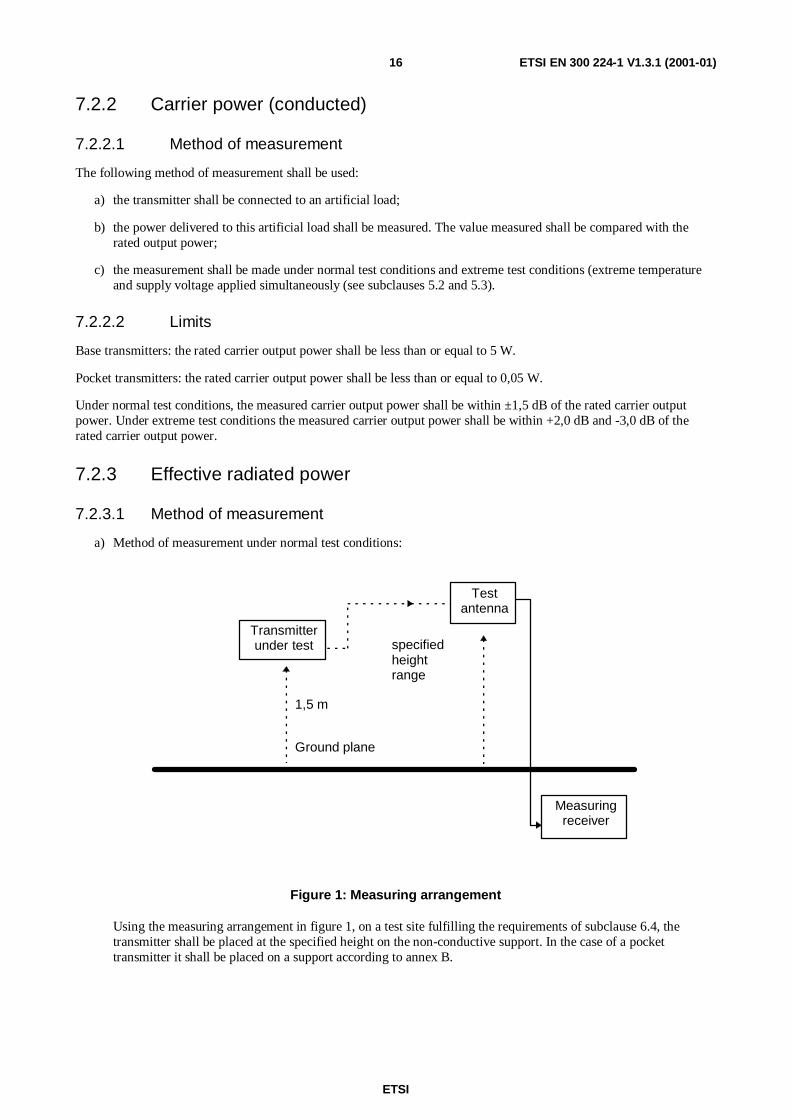
a) Method of measurement under normal test conditions:
Transmitterunder test
Testantenna
Measuringreceiver
1,5 m
Ground plane
specifiedheightrange
Figure 1: Measuring arrangement
Using the measuring arrangement in figure 1, on a test site fulfilling the requirements of subclause 6.4, thetransmitter shall be placed at the specified height on the non-conductive support. In the case of a pockettransmitter it shall be placed on a support according to annex B.
ETSI
ETSI EN 300 224-1 V1.3.1 (2001-01)17
The position shall be as follows:
- for transmitters with an internal antenna, it shall stand in the position in which it is normally used;
- for transmitters with a rigid external antenna, the antenna shall be vertical;
- for transmitters with a non-rigid external antenna, with the antenna extended vertically upwards by anon-conducting support.
The transmitter shall be switched on, if possible without modulation, and the measuring receiver shall be tunedto the frequency of the signal being measured.
The test antenna shall be orientated for vertical polarization.
The signal level shall be measured as follows:
1) the transmitter shall be rotated through 360° until the maximum signal is detected on the measuring receiver;
2) then the test antenna shall be raised or lowered over a range of 1 m to 4 m, until the maximum signal isreceived.
NOTE: This maximum may be lower than the value obtainable at heights outside the specified limits.
Steps 1) and 2) above shall be repeated to ensure that the direction of maximum field strength is found.
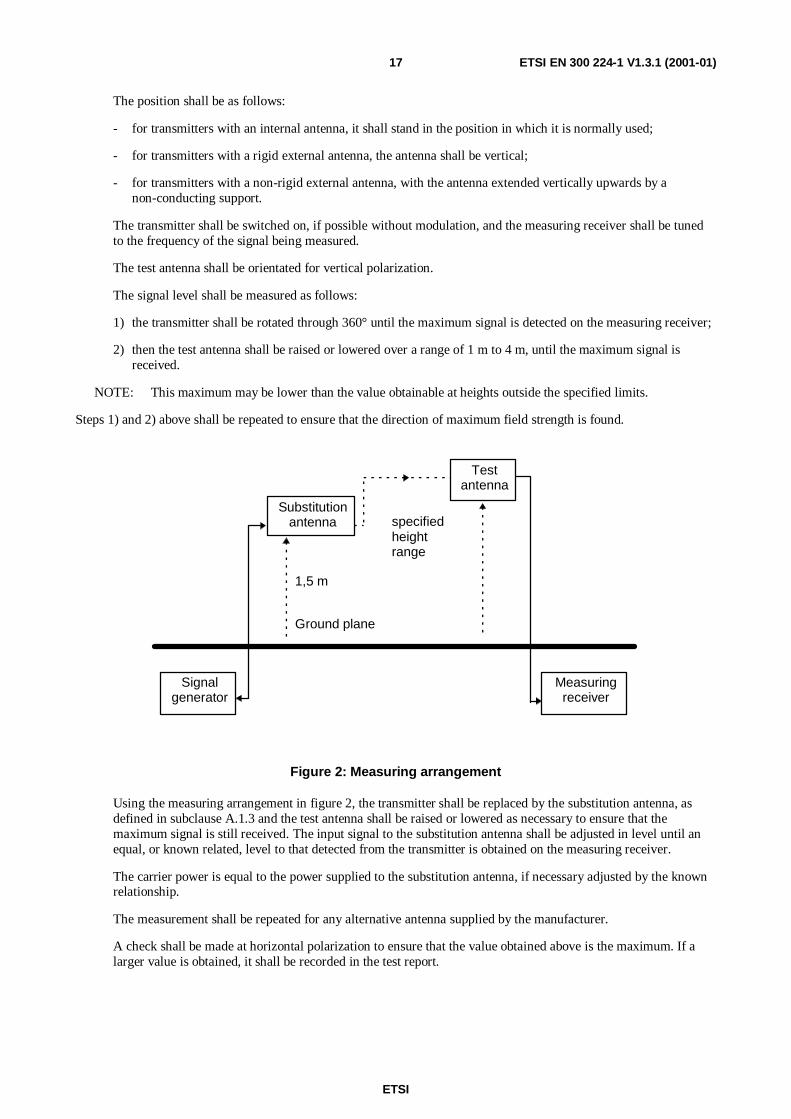
Substitutionantenna
Testantenna
Signalgenerator
Measuringreceiver
1,5 m
Ground plane
specifiedheightrange
Figure 2: Measuring arrangement
Using the measuring arrangement in figure 2, the transmitter shall be replaced by the substitution antenna, asdefined in subclause A.1.3 and the test antenna shall be raised or lowered as necessary to ensure that themaximum signal is still received. The input signal to the substitution antenna shall be adjusted in level until anequal, or known related, level to that detected from the transmitter is obtained on the measuring receiver.
The carrier power is equal to the power supplied to the substitution antenna, if necessary adjusted by the knownrelationship.
The measurement shall be repeated for any alternative antenna supplied by the manufacturer.
A check shall be made at horizontal polarization to ensure that the value obtained above is the maximum. If alarger value is obtained, it shall be recorded in the test report.
ETSI
ETSI EN 300 224-1 V1.3.1 (2001-01)18
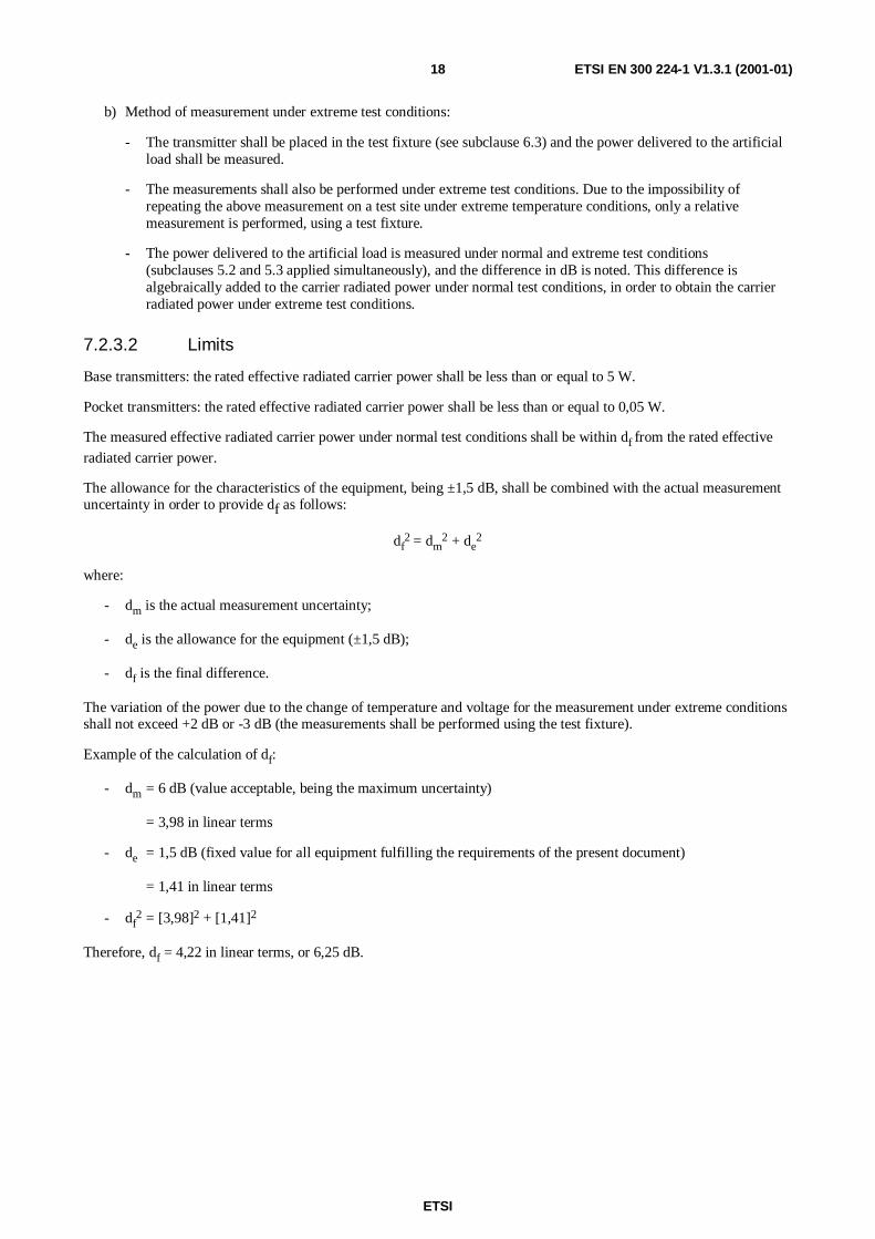
b) Method of measurement under extreme test conditions:
- The transmitter shall be placed in the test fixture (see subclause 6.3) and the power delivered to the artificialload shall be measured.
- The measurements shall also be performed under extreme test conditions. Due to the impossibility ofrepeating the above measurement on a test site under extreme temperature conditions, only a relativemeasurement is performed, using a test fixture.
- The power delivered to the artificial load is measured under normal and extreme test conditions(subclauses 5.2 and 5.3 applied simultaneously), and the difference in dB is noted. This difference isalgebraically added to the carrier radiated power under normal test conditions, in order to obtain the carrierradiated power under extreme test conditions.
7.2.3.2 Limits
Base transmitters: the rated effective radiated carrier power shall be less than or equal to 5 W.
Pocket transmitters: the rated effective radiated carrier power shall be less than or equal to 0,05 W.
The measured effective radiated carrier power under normal test conditions shall be within df from the rated effective
radiated carrier power.
The allowance for the characteristics of the equipment, being ±1,5 dB, shall be combined with the actual measurementuncertainty in order to provide df as follows:
df2 = dm
2 + de2
where:
- dm is the actual measurement uncertainty;
- de is the allowance for the equipment (±1,5 dB);
- df is the final difference.
The variation of the power due to the change of temperature and voltage for the measurement under extreme conditionsshall not exceed +2 dB or -3 dB (the measurements shall be performed using the test fixture).
Example of the calculation of df:
- dm = 6 dB (value acceptable, being the maximum uncertainty)
= 3,98 in linear terms
- de = 1,5 dB (fixed value for all equipment fulfilling the requirements of the present document)
= 1,41 in linear terms
- df2 = [3,98]2 + [1,41]2
Therefore, df = 4,22 in linear terms, or 6,25 dB.

ETSI
ETSI EN 300 224-1 V1.3.1 (2001-01)19
7.3 Adjacent channel power
7.3.1 Definition
The adjacent channel power is that part of the total output power of a transmitter modulated under a defined conditionof modulation which falls within a specified pass band centred on the nominal frequency of either of the adjacentchannels. This power is the sum of the mean power produced by the modulation, hum and noise of the transmitter. It isspecified either as the ratio expressed in decibels of the carrier power to the adjacent channel power or as an absolutevalue.
7.3.2 Method of measurement
Transmitterunder test
Artificialload
Powermeasuringreceiver
Modulatingsignal
generator
Figure 3: Measuring arrangement
Using the measuring arrangement given in figure 3, the adjacent channel power shall be measured with a powermeasuring receiver which conforms with annex C.
a) The transmitter under test shall be connected via the artificial load to a measuring receiver calibrated to measureroot-mean-squared (rms) power levels. The level at the input of the measuring receiver shall be within itsspecified limit(s). The transmitter shall be operated at the maximum operational carrier power level.
In the case of a transmitter without a 50 Ω antenna connection, the transmitter shall be placed in the test fixture,and the test fixture shall be connected to the measuring receiver.
NOTE: When using the test fixture for this measurement, it is important to ensure that direct radiation from thetransmitter to the power measuring receiver does not affect the result.
b) With the transmitter unmodulated, the tuning of the power measuring receiver shall be adjusted so that amaximum response is obtained. This is the 0 dB response point. The power measuring receiver attenuator settingand the meter reading shall be recorded.
c) The tuning of the power measuring receiver shall be adjusted away from the carrier so that its -6 dB responsenearest to the transmitter carrier frequency is located at a displacement from the nominal frequency of the carrieras given in table 2.
Table 2: Frequency displacement
Channel spacing (kHz) Displacement(kHz)
10 5,7512,5 8,2520 1325 17
The same result may be obtained by tuning the power measuring receiver (point D0 on the power measuringfilter shape, given in figure C.1, annex C), to the nominal frequency of the adjacent channel, if it has beensuitably calibrated.
ETSI
ETSI EN 300 224-1 V1.3.1 (2001-01)20
d) The transmitter shall be modulated in accordance with subclause 6.1.2 with the normal coded test signal D-M3 atthe input level declared by the manufacturer. Additionally, where the transmitter has a speech facility, the testshall be repeated with normal test signal A-M2 according to subclause 6.1.1 increased by 20 dB. In the case of atransmitter with an integrated microphone the level shall be increased by 10 dB.
e) The power measuring receiver variable attenuator shall be adjusted to obtain the same meter reading as in step b)or a known relation to it. This value shall be recorded.
f) The ratio of adjacent channel power to carrier power is the difference between the attenuator settings in steps b)and e), corrected for any differences in the reading of the meter. Alternatively the absolute value of the adjacentchannel power may be calculated from the above ratio and the transmitter carrier power.
g) Steps c) to f) shall be repeated with the power measuring receiver tuned to the other side of the carrier.
h) Steps a) to g) shall be repeated with the transmitter set to its minimum operational power level.
7.3.3 Limits
The limits for the adjacent channel power under normal conditions are given in table 3.
Table 3
Channel spacing (kHz) Limit under normal conditions Limit under extreme conditions10 20 µW 25 µW
12,5 60 dB below carrier power, without theneed to be below 0,2 µW
55 dB below carrier power, without theneed to be below 0,2 µW
20/25 70 dB below carrier power, without theneed to be below 0,2 µW
65 dB below carrier power, without theneed to be below 0,2 µW
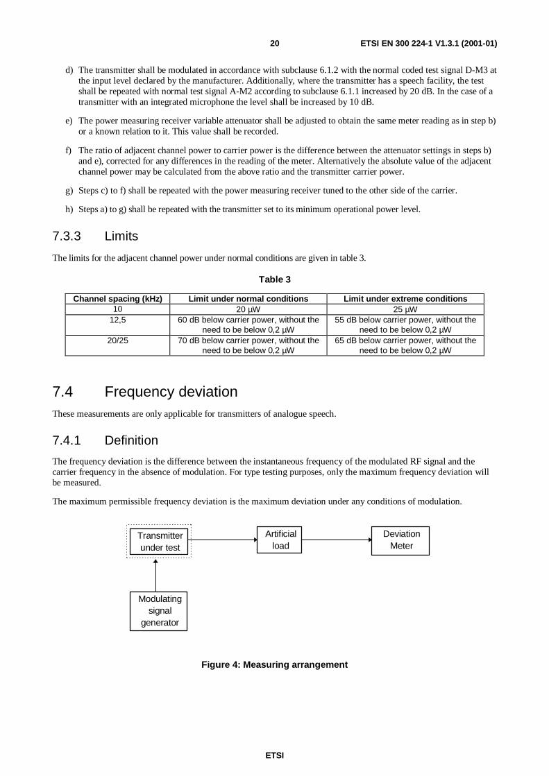
7.4 Frequency deviationThese measurements are only applicable for transmitters of analogue speech.
7.4.1 Definition
The frequency deviation is the difference between the instantaneous frequency of the modulated RF signal and thecarrier frequency in the absence of modulation. For type testing purposes, only the maximum frequency deviation willbe measured.
The maximum permissible frequency deviation is the maximum deviation under any conditions of modulation.
Transmitterunder test
Artificialload
DeviationMeter
Modulatingsignal
generator
Figure 4: Measuring arrangement
ETSI
ETSI EN 300 224-1 V1.3.1 (2001-01)21
7.4.2 Method of measurement
Using the measuring arrangement given in figure 4, the transmitter shall be connected to the artificial load. Thefrequency deviation shall be measured by means of a deviation meter capable of measuring the maximum permissiblefrequency deviation, including that due to any harmonics and intermodulation products which may be produced in thetransmitter.
In case of transmitters without a 50 Ω connection, the transmitter shall be placed in the test fixture and the test fixtureshall be connected to the artificial load.
7.4.3 Analogue signals within the audio bandwidth
7.4.3.1 Method of measurement
The following test method shall be used:
a) the modulation frequency shall be varied between:
- 300 and 3 000 Hz for equipment operating with 20 kHz or 25 kHz channel separation; and
- between 300 Hz and 2 550 Hz for equipment operating with 10 kHz or 12,5 kHz channel separation.
The level of the test signal shall be 20 dB above the level of the normal signal A-M1 (see subclause 6.1.1) or10 dB in case of a transmitter with an integrated microphone.
b) the maximum (positive or negative) frequency deviation shall be recorded.
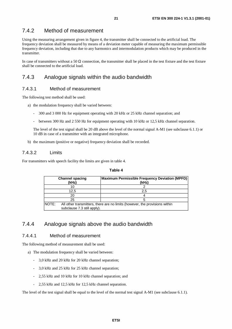
7.4.3.2 Limits
For transmitters with speech facility the limits are given in table 4.
Table 4
Channel spacing(kHz)
Maximum Permissible Frequency Deviation (MPFD)(kHz)
10 212,5 2,520 425 5
NOTE: All other transmitters, there are no limits (however, the provisions withinsubclause 7.3 still apply).
7.4.4 Analogue signals above the audio bandwidth
7.4.4.1 Method of measurement
The following method of measurement shall be used:
a) The modulation frequency shall be varied between:
- 3,0 kHz and 20 kHz for 20 kHz channel separation;
- 3,0 kHz and 25 kHz for 25 kHz channel separation;
- 2,55 kHz and 10 kHz for 10 kHz channel separation; and
- 2,55 kHz and 12,5 kHz for 12,5 kHz channel separation.
The level of the test signal shall be equal to the level of the normal test signal A-M1 (see subclause 6.1.1).

ETSI
ETSI EN 300 224-1 V1.3.1 (2001-01)22
7.4.4.2 Limits
Between 3,0 kHz/2,55 kHz and 6 kHz the frequency deviation shall not exceed the frequency deviation at a modulationfrequency of 3,0 kHz/2,55 kHz.
At 6 kHz the deviation shall not be more than 30 % of the maximum permissible frequency deviation (see table 4 insubclause 7.4.3.2).
The frequency deviation at modulation frequencies between 6,0 kHz and a frequency equal to the channel separation forwhich the equipment is intended shall not exceed the value given by linear representation of the frequency deviation(dB) relative to the modulation frequency, starting at the 6,0 kHz limit and having a slope of -14,0 dB per octave.
These limits are illustrated in figure 5.
MPFD
A
30 %MPFD
f f 6 kHz f1 2 cs
Frequency deviation Audio frequency
-14 dB/oct
-14 dB/oct
f1: Lowest appropriate frequency.f2: 3,0 kHz (for 20 kHz or 25 kHz channel separation); or
2,55 kHz (for 12,5 kHz or 10 kHz channel separation).MPFD: Maximum permissible frequency deviation, subclause 7.4.3.2.A: Measured frequency deviation at f2.fcs: Frequency equal to channel separation.
Figure 5
The maximum (positive or negative) frequency deviation shall be recorded.
7.5 Spurious emissions
7.5.1 Definition
Spurious emissions are emissions at frequencies other than those of the carrier and sidebands associated with normalmodulation.
The level of spurious emissions shall be measured as either:
a) their power level in a specified load (conducted spurious radiation) and their effective radiated power whenradiated by the cabinet and structure of the equipment (cabinet radiation); or
ETSI
ETSI EN 300 224-1 V1.3.1 (2001-01)23
b) their effective radiated power when radiated by the cabinet and the integral antenna, in the case of pocketequipment fitted with such an antenna and having no external RF connector.
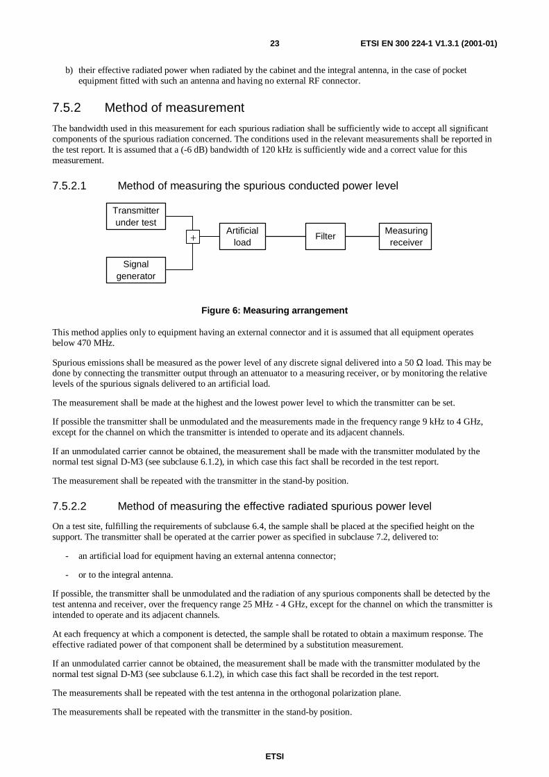
7.5.2 Method of measurement
The bandwidth used in this measurement for each spurious radiation shall be sufficiently wide to accept all significantcomponents of the spurious radiation concerned. The conditions used in the relevant measurements shall be reported inthe test report. It is assumed that a (-6 dB) bandwidth of 120 kHz is sufficiently wide and a correct value for thismeasurement.
7.5.2.1 Method of measuring the spurious conducted power level
Transmitterunder test
Signalgenerator
Artificialload
FilterMeasuringreceiver+
Figure 6: Measuring arrangement
This method applies only to equipment having an external connector and it is assumed that all equipment operatesbelow 470 MHz.
Spurious emissions shall be measured as the power level of any discrete signal delivered into a 50 Ω load. This may bedone by connecting the transmitter output through an attenuator to a measuring receiver, or by monitoring the relativelevels of the spurious signals delivered to an artificial load.
The measurement shall be made at the highest and the lowest power level to which the transmitter can be set.
If possible the transmitter shall be unmodulated and the measurements made in the frequency range 9 kHz to 4 GHz,except for the channel on which the transmitter is intended to operate and its adjacent channels.
If an unmodulated carrier cannot be obtained, the measurement shall be made with the transmitter modulated by thenormal test signal D-M3 (see subclause 6.1.2), in which case this fact shall be recorded in the test report.
The measurement shall be repeated with the transmitter in the stand-by position.
7.5.2.2 Method of measuring the effective radiated spurious power level
On a test site, fulfilling the requirements of subclause 6.4, the sample shall be placed at the specified height on thesupport. The transmitter shall be operated at the carrier power as specified in subclause 7.2, delivered to:
- an artificial load for equipment having an external antenna connector;
- or to the integral antenna.
If possible, the transmitter shall be unmodulated and the radiation of any spurious components shall be detected by thetest antenna and receiver, over the frequency range 25 MHz - 4 GHz, except for the channel on which the transmitter isintended to operate and its adjacent channels.
At each frequency at which a component is detected, the sample shall be rotated to obtain a maximum response. Theeffective radiated power of that component shall be determined by a substitution measurement.
If an unmodulated carrier cannot be obtained, the measurement shall be made with the transmitter modulated by thenormal test signal D-M3 (see subclause 6.1.2), in which case this fact shall be recorded in the test report.
The measurements shall be repeated with the test antenna in the orthogonal polarization plane.
The measurements shall be repeated with the transmitter in the stand-by position.

ETSI
ETSI EN 300 224-1 V1.3.1 (2001-01)24
7.5.3 Limits
The limits for conducted emission are given in table 5.
Table 5: Conducted emissions
Frequency range 9 kHz to 1 GHz above 1 GHz to 4 GHzTx operating 0,25 µW 1 µW
Tx stand-by 2 nW 20 nW
The limits for radiated emissions are given in table 6.
Table 6: Radiated emissions
Frequency range 25 MHz to 1 GHz above 1 GHz to 4 GHzTx operating 0,25 µW 1 µ W
Tx stand-by 2 nW 20 nW
NOTE: It is assumed that all equipment operates below 470 MHz.
7.6 Transmitter transient behaviour
7.6.1 Definition
The transient behaviour of transmitters is determined by the time-dependency of the transmitter frequency and thetransmitter power when the transmitter output power is switched on and off. Within the scope of the present document,only the transient behaviour of the transmitter carrier frequency shall be measured.
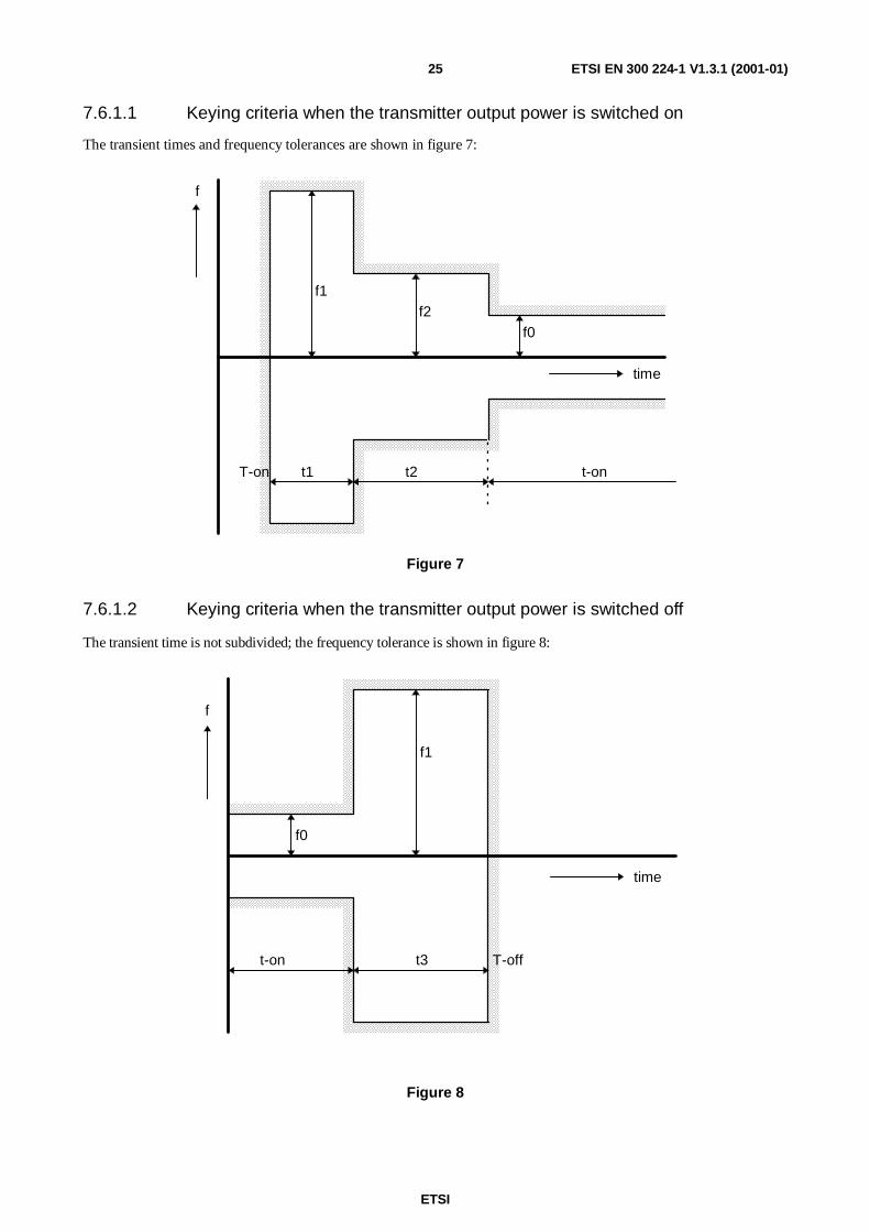
The following frequency tolerances and transient times are specified:
f0: frequency tolerance in the steady state;
f1: frequency difference which shall be less than one channel separation;
f2: frequency difference which shall not be greater than half the channel separation;
t1: period of time during which frequency tolerance f1 applies;
t2: period of time during which frequency tolerance f2 applies;
t3: period of time during which the frequency error on the carrier applies;
ton: period of time during which frequency tolerance f0 applies.
According to the method of measurement described in subclause 7.6.2, the switch-on instant (Ton) of a transmitter is
defined by the condition when the output power, measured at the antenna terminal, exceeds 10 % of the nominal power.However, this value shall not be greater than 100 mW. The switch-off instant (Toff) is given when the nominal power
falls below this limit.
The different frequency tolerance schemes have to be applied for the following cases.
ETSI
ETSI EN 300 224-1 V1.3.1 (2001-01)25
7.6.1.1 Keying criteria when the transmitter output power is switched on
The transient times and frequency tolerances are shown in figure 7:
f
f1f2
f0
time
t1 t2 t-onT-on
Figure 7
7.6.1.2 Keying criteria when the transmitter output power is switched off
The transient time is not subdivided; the frequency tolerance is shown in figure 8:
f
time
t-on t3
f0
f1
T-off
Figure 8
ETSI
ETSI EN 300 224-1 V1.3.1 (2001-01)26
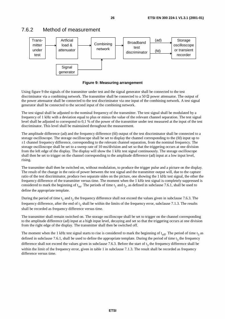
7.6.2 Method of measurement
Trans-mitterundertest
Artficialload &
attenuator
Combiningnetwork
Broadbandtest
discriminator
Storageoscilloscopeor transient
recorder
Signalgenerator
(ad)
(fd)
Figure 9: Measuring arrangement
Using figure 9 the signals of the transmitter under test and the signal generator shall be connected to the testdiscriminator via a combining network. The transmitter shall be connected to a 50 Ω power attenuator. The output ofthe power attenuator shall be connected to the test discriminator via one input of the combining network. A test signalgenerator shall be connected to the second input of the combining network.
The test signal shall be adjusted to the nominal frequency of the transmitter. The test signal shall be modulated by afrequency of 1 kHz with a deviation equal to plus or minus the value of the relevant channel separation. The test signallevel shall be adjusted to correspond to 0,1 % of the power of the transmitter under test measured at the input of the testdiscriminator. This level shall be maintained throughout the measurement.
The amplitude difference (ad) and the frequency difference (fd) output of the test discriminator shall be connected to astorage oscilloscope. The storage oscilloscope shall be set to display the channel corresponding to the (fd) input up to±1 channel frequency difference, corresponding to the relevant channel separation, from the nominal frequency. Thestorage oscilloscope shall be set to a sweep rate of 10 ms/division and set so that the triggering occurs at one divisionfrom the left edge of the display. The display will show the 1 kHz test signal continuously. The storage oscilloscopeshall then be set to trigger on the channel corresponding to the amplitude difference (ad) input at a low input level,rising.
The transmitter shall then be switched on, without modulation, to produce the trigger pulse and a picture on the display.The result of the change in the ratio of power between the test signal and the transmitter output will, due to the captureratio of the test discriminator, produce two separate sides on the picture, one showing the 1 kHz test signal, the other thefrequency difference of the transmitter versus time. The moment when the 1 kHz test signal is completely suppressed isconsidered to mark the beginning of ton. The periods of time t1 and t2, as defined in subclause 7.6.1, shall be used to
define the appropriate template.
During the period of time t1 and t2 the frequency difference shall not exceed the values given in subclause 7.6.3. The
frequency difference, after the end of t2 shall be within the limits of the frequency error, subclause 7.1.3. The resultsshall be recorded as frequency difference versus time.
The transmitter shall remain switched on. The storage oscilloscope shall be set to trigger on the channel correspondingto the amplitude difference (ad) input at a high input level, decaying and set so that the triggering occurs at one divisionfrom the right edge of the display. The transmitter shall then be switched off.
The moment when the 1 kHz test signal starts to rise is considered to mark the beginning of toff. The period of time t3 asdefined in subclause 7.6.1, shall be used to define the appropriate template. During the period of time t3 the frequency
difference shall not exceed the values given in subclause 7.6.3. Before the start of t3 the frequency difference shall be
within the limit of the frequency error, given in table 1 in subclause 7.1.3. The result shall be recorded as frequencydifference versus time.

ETSI
ETSI EN 300 224-1 V1.3.1 (2001-01)27
7.6.3 Limits
Table 7: Base station transmitters
Transienttime
Carrier frequency≤≤≤≤ 300 MHz
Carrier frequency> 300 MHz
Maximum frequencydeviation
t1 5 ms 10 ms 1,0 channel separationt2 20 ms 25 ms 0,5 channel separationt3 5 ms 10 ms 1,0 channel separation
NOTE: For pocket transmitters there is no limit.
8 Receiver requirements
8.1 Pocket paging receivers
8.1.1 Spurious emissions
8.1.1.1 Definition
Spurious emissions from receivers are any emissions radiated from the unit. They are specified as the radiated power ofany discrete signal.
8.1.1.2 Method of measurement
On a test site fulfilling the requirements of subclause 6.4, the sample receiver shall be placed at the specified height on anon-conductive support and the receiver shall be switched on.
Radiation of any spurious component shall be detected by the test antenna and measuring receiver over the frequencyrange 25 MHz to 4 GHz.
At each frequency at which a component is detected:
1) the receiver under test shall be rotated through 360° until the maximum signal is detected on the measuringreceiver;
2) the test antenna shall be raised or lowered through the specified height range until the maximum signal isreceived.
NOTE: This maximum may be lower than the value obtainable at heights outside the specified limits.
Steps 1) and 2) shall be repeated to ensure that the direction of maximum field-strength is found. After that asubstitution method shall be carried out to precisely define the power of the spectral component.
The measurements shall be repeated with the test antenna in the orthogonal polarization plane.
ETSI
ETSI EN 300 224-1 V1.3.1 (2001-01)28
8.1.1.3 Limits
The power of any spurious component in the specified range of frequencies shall not exceed:
- 2 nW below 1 GHz; and
- 20 nW above 1 GHz.
8.2 Base station receivers
8.2.1 Measured sensitivity for analogue speech
8.2.1.1 Definition
The measured sensitivity for analogue speech of the receiver is the minimum level of signal at the nominal frequency ofthe receiver which produces, through a psophometric weighting network, a (SIgnal + Noise And Distortion) / (Noise +Distortion) ratio (SINAD) ratio of 20 dB.
8.2.1.2 Method of measurement
A signal generator shall be connected to the receiver input. The signal generator shall be at the nominal frequency andmodulated with the test modulation A-M1 (see subclause 6.1.1) and the amplitude shall be adjusted until a weightedSINAD ratio of 20 dB is obtained.
The test signal input level under these conditions is the value of the measured sensitivity for analogue speech. Thisinput level is measured where the receiver input is to be connected but while the receiver input remains unconnected.
The measurement shall be repeated under extreme test conditions.
8.2.1.3 Limits
The measured sensitivity values shall not exceed +6 dBµV emf under normal conditions, and +12 dBµV emf underextreme test conditions.
8.2.2 Measured sensitivity for messages
8.2.2.1 Definition
The measured sensitivity for messages of the receiver is the minimum level of signal at the nominal frequency of thereceiver which produces, after demodulation, a message acceptance ratio of 80 %.
8.2.2.2 Method of measurement
a) A signal generator shall be connected to the receiver input. The signal generator shall be at the nominalfrequency and modulated with the test signal D-M3 (see subclause 6.1.2).
b) The amplitude of the signal generator shall be adjusted until a successful message response rate of 10 % isobtained.
c) The test signal shall be applied repeatedly whilst observing in each case whether or not a successful response isobtained. The input level shall be increased by 2 dB for each occasion that a successful response is not obtained.The procedure shall be continued until three consecutive successful responses are observed. The level of theinput signal shall be measured. This input level is measured where the receiver input is to be connected but whilethe receiver input remains unconnected.
ETSI
ETSI EN 300 224-1 V1.3.1 (2001-01)29
d) The input signal level shall be reduced by 1 dB and the new value recorded. The test signal shall then becontinuously repeated. In each case, if a response is not obtained, the input level shall be increased by 1 dB andthe new value recorded. If a successful response is obtained, the input level shall not be changed until threeconsecutive successful responses have been observed. In this case the input level shall be reduced by 1 dB andthe new value recorded. No input signal levels shall be recorded unless preceded by a change in level. Themeasurement shall be stopped after a total of 10 values has been recorded.
e) The measured sensitivity for messages is the average of the values recorded in steps c) and d). This value shallbe recorded.
f) The measurement shall be repeated under extreme test conditions.
8.2.2.3 Limits
The measured sensitivity value shall not exceed +3 dBµV emf under normal test conditions, and +9 dBµV emf underextreme test conditions.
8.2.3 Co-channel rejection for analogue speech
8.2.3.1 Definition
The co-channel rejection for analogue speech is a measure of the capability of the receiver to receive a wantedmodulated signal at the nominal frequency without exceeding a given degradation due to the presence of an unwantedmodulated signal, also at the nominal frequency.
It is specified as the ratio in dB of the level of the unwanted signal to the specified wanted signal level at the receiverinput, which produces through a psophometric weighting network a SINAD ratio of 14 dB.
8.2.3.2 Method of measurement
Two signal generators, A and B, shall be connected to the receiver input via a combining network. The wanted signal,represented by generator A, shall be at the nominal frequency and modulated with the test signal A-M1. The signal levelof generator A shall be 6 dBµV emf under normal test conditions. This level is measured where the receiver input is tobe connected but while the receiver input remains unconnected.
The unwanted signal, represented by generator B, shall also be at the nominal frequency and modulated with the testsignal A-M3 (see subclause 6.1.1) and adjusted until the SINAD ratio of 14 dB is obtained.
The co-channel ratio for analogue speech shall be recorded as the ratio in dB of the level of the unwanted signal to thelevel of the wanted signal at the receiver input.
8.2.3.3 Limits
The co-channel rejection ratio shall be between:
- -8 dB and 0 dB for a channel separation of 20 kHz and 25 kHz;
- -12 dB and 0 dB for a channel separation of 10 kHz and 12,5 kHz.
8.2.4 Co-channel rejection for messages
8.2.4.1 Definition
The co-channel rejection for messages is a measure of the capability of the receiver to receive a wanted modulatedsignal at the nominal frequency without exceeding a given degradation due to the presence of an unwanted modulatedsignal, also at the nominal frequency.
It is specified as the ratio in dB of the level of the unwanted signal to the specified wanted signal level at the receiverinput, for which the message acceptance ratio is 80 %.
ETSI
ETSI EN 300 224-1 V1.3.1 (2001-01)30
8.2.4.2 Method of measurement
a) Two signal generators, A and B, shall be connected to the receiver input via a combining network. The wantedsignal, represented by generator A, shall be at the nominal frequency and modulated with test signal D-M3 (seesubclause 6.1.2). The signal level of generator A shall be 6 dBµV emf under normal test conditions. This level ismeasured where the receiver input is to be connected but while the receiver input remains unconnected.
b) The unwanted signal, represented by generator B, shall also be at the nominal frequency and modulated with thetest signal A-M3 (see subclause 6.1.1) and adjusted until a successful message ratio of less than 10 % isobtained.
c) The level of the unwanted signal shall be reduced by 2 dB for each occasion that a successful response is notobserved. The procedure shall be continued until three consecutive successful responses are observed. The levelof the input signal shall then be measured. This level is measured where the receiver input is to be connected butwhile the receiver input remains unconnected.
d) The unwanted input signal shall then be increased by 1 dB and the new value recorded. The wanted signal, asdetermined in c) above, shall then be continuously repeated. In each case if a response is not obtained the levelof the unwanted signal shall be reduced by 1 dB and the new value recorded. If a successful response is obtained,the level of the unwanted signal shall not be changed until three consecutive responses have been obtained. Inthis case the unwanted signal shall be increased by 1 dB and the new value recorded. No levels of the unwantedsignal shall be recorded unless preceded by a change in level. The measurement shall be stopped after a total of10 values have been recorded.
e) The co-channel rejection ratio for messages shall be recorded as the ratio in dB of the average of the levels of theunwanted signal recorded in steps c) and d) to the level of the wanted signal, at the receiver input.
8.2.4.3 Limits
The co-channel rejection ratio shall be between:
• -8 dB and 0 dB for a channel separation of 20 kHz and 25 kHz;
• -12 dB and 0 dB for a channel separation of 10 kHz and 12,5 kHz.
8.2.5 Adjacent channel selectivity for analogue speech
8.2.5.1 Definition
The adjacent channel selectivity for analogue speech is a measure of the capability of the receiver to receive a wantedmodulated signal at the nominal frequency without exceeding a given degradation due to the presence of an unwantedmodulated signal which differs in frequency from the wanted signal by an amount equal to the adjacent channelseparation for which the equipment is intended.
It is specified as the lower value of the ratios in dB, for the upper and lower adjacent channels, of the level of theunwanted signal to a specified level of the wanted signal which produces through a psophometric weighting network aSINAD ratio of 14 dB.
8.2.5.2 Method of measurement
Two signal generators, A and B, shall be connected to the receiver input via a combining network. The wanted signal,represented by generator A, shall be at the nominal frequency and modulated with the test signal A-M1 (seesubclause 6.1.1). The signal level of generator A shall be 6 dBµV emf under normal test conditions and +12 dBµV emfunder extreme test conditions. This level is measured where the receiver input is to be connected but while the receiverinput remains unconnected.
The unwanted modulated signal, represented by generator B and modulated with the test signal A-M3, (seesubclause 6.1.1) shall be at the channel frequency immediately above that of the wanted signal.
The level of generator B shall be adjusted until the SINAD ratio of 14 dB is obtained. The ratio in dB of the level of theunwanted signal to the level of the wanted signal at the receiver input shall be recorded.
ETSI
ETSI EN 300 224-1 V1.3.1 (2001-01)31
The measurement shall be repeated with an unwanted signal at the frequency of the channel below that of the wantedsignal and the ratio in dB of the level of the unwanted signal to the level of the wanted signal at the receiver input shallbe recorded.
The measurement shall be repeated under extreme test conditions using the relevant value of the wanted signal.
8.2.5.3 Limits
The lower value of the ratio in dB of the upper and lower adjacent channels shall, for different channel separations, notbe less than the value given in table 8.
Table 8
Conditions Channel spacing10/12,5 kHz 20 /25 kHz
normal 60 dB 70 dBextreme 50 dB 60 dB
8.2.6 Adjacent channel selectivity for messages
8.2.6.1 Definition
The adjacent channel selectivity for messages is a measure of the capability of the receiver to receive a wantedmodulated signal at the nominal frequency without exceeding a given degradation due to the presence of an unwantedmodulated signal which differs in frequency from the wanted signal by an amount equal to the adjacent channelseparation for which the equipment is intended.
It is specified as the lower value of the ratios in dB for the upper and lower adjacent channels of the level of theunwanted signal to a specified level of the wanted signal, for which the message acceptance rate is 80 %.
8.2.6.2 Method of measurement
a) Two signal generators, A and B, shall be connected to the receiver input via a combining network. The wantedsignal, represented by generator A, shall be at the nominal frequency and modulated with the test signal D-M3(see subclause 6.1.2). The signal level of generator A shall be 6 dBµV emf under normal test conditions and+12 dBµV emf under extreme test conditions. This level is measured where the receiver input is to be connectedbut while the receiver input remains unconnected.
b) The unwanted signal, modulated by the test signal A-M3 (see subclause 6.1.1) and represented by generator B,shall be at the channel frequency immediately above that of the wanted signal. The level of generator B shall beadjusted until a successful message ratio of less than 10 % is obtained.
c) The level of the unwanted signal shall be reduced by 2 dB for each occasion that a successful response is notobserved. The procedure shall be continued until three consecutive successful responses are observed. The levelof the input signal shall then be measured. This level is measured where the receiver input is to be connected butwhile the receiver input remains unconnected.
d) The unwanted input signal shall then be increased by 1 dB and the new value recorded. The wanted signal, asdetermined in c) above, shall then be continuously repeated. In each case a response is not obtained the level ofthe unwanted signal shall be reduced by 1 dB and the new value recorded. If a successful response is obtained,the level of the unwanted signal shall not be changed until three consecutive successful responses have beenobtained. In this case the unwanted signal shall be increased by 1 dB and the new value recorded. No levels ofthe unwanted signal shall be recorded unless preceded by a change in level. The measurement shall be stoppedafter a total of 10 values have been recorded.
e) The measurement shall be repeated with the unwanted signal at the frequency of the channel below that of thewanted signal.
f) The adjacent channel selectivity for messages shall be recorded for the upper and lower adjacent channels as theaverage of the levels of the unwanted signal, recorded in steps c) and d), to the level of the wanted input signal.

ETSI
ETSI EN 300 224-1 V1.3.1 (2001-01)32
8.2.6.3 Limits
The lower value of the ratio in dB of the upper and lower adjacent channels shall, for different channel separations, notbe less than the value given in table 9.
Table 9
Conditions Channel spacing10/12,5 kHz 20/25 kHz
normal 60 dB 70 dBextreme 50 dB 60 dB
8.2.7 Spurious response immunity for analogue speech
8.2.7.1 Definition
The spurious response immunity for analogue speech is a measure of the capability of the receiver to receive a wantedmodulated signal at the nominal frequency without exceeding a given degradation due to the presence of an unwantedmodulated signal at any other frequency, that differs from the wanted signal by more than one channel separation, andat which a response is obtained.
It is specified as the value of the ratio in dB of the level of the unwanted signal to a specified level of the wanted signalwhich produces, through a psophometric weighting network, a SINAD ratio of 14 dB.
8.2.7.2 Method of measurement
Two signal generators, A and B, shall be connected to the receiver input via a combining network. The wanted signal,represented by generator A, shall be at the nominal frequency and modulated with the normal test signal A-M1 (seesubclause 6.1.1). The signal level of generator A shall be 6 dBµV emf. This level is measured where the receiver inputis to be connected but while the receiver input remains unconnected.
The level of the unwanted signal, modulated by the test signal A-M3 (see subclause 6.1.1) and represented bygenerator B, shall be adjusted to 80 dB above the level of the wanted signal, when measured at the receiver input. Thefrequency of the unwanted signal shall than be varied over the frequency range 100 kHz to 2 GHz plus otherfrequencies within the full specified frequency range at which it is calculated that a spurious response could occur. Thefrequencies of all responses shall be noted.
At any frequency where a response is obtained, the unwanted modulated signal level shall be adjusted until a SINADratio of 14 dB is obtained. The spurious response immunity shall be recorded for the frequency concerned as the ratio indB between the unwanted modulated signal and the wanted signal at the receiver input.
8.2.7.3 Limit
The spurious response immunity for analogue speech shall not be less than 70 dB.
8.2.8 Spurious response immunity for messages
8.2.8.1 Definition
The spurious response immunity for messages is a measure of the capability of the receiver to receive a wanted signal atthe nominal frequency without exceeding a given degradation due to the presence of an unwanted modulated signal atany other frequency, that differs from the wanted signal by more than one channel separation, and at which a responseis obtained.
It is specified as the value of the ratios in dB of the level of the unwanted signal to a specified level of the wantedsignal, for which the message acceptance rate is 80 %.
ETSI
ETSI EN 300 224-1 V1.3.1 (2001-01)33
8.2.8.2 Method of measurement
a) Two signal generators, A and B, shall be connected to the receiver input via a combining network. The wantedsignal, represented by generator A, shall be at the nominal frequency and modulated with the test signal D-M3(see subclause 6.1.2). The signal level of generator A shall be adjusted to 6 dBµV emf. This level is measuredwhere the receiver input is to be connected but while the receiver input remains unconnected.
b) The frequency of the unwanted signal, modulated by the test signal A-M3 (see subclause 6.1.1) and representedby generator B, shall be adjusted to a frequency within the specified frequency range at which it is calculatedthat a spurious response could occur. The level of the unwanted modulated signal shall be adjusted until asuccessful message ratio of less than 10 % is obtained.
c) The level of the unwanted signal shall be reduced by 2 dB for each occasion that a successful response is notobserved. The procedure shall be continued until three consecutive successful responses are observed. The levelof the input signal shall then be measured. This level is measured where the receiver input is to be connected butwhile the receiver input remains unconnected.
d) The unwanted input signal shall then be increased by 1 dB and the new value recorded. The wanted signal shallthen be continuously repeated. In each case a response is not obtained the level of the unwanted signal shall bereduced by 1 dB and the new value recorded. If a successful response is obtained, the level of the unwantedsignal shall not be changed until three consecutive successful responses have been obtained. In this case theunwanted signal shall be increased by 1 dB and the new value recorded. No levels of the unwanted signal shallbe recorded unless preceded by a change in level. The measurement shall be stopped after a total of 10 valueshas been recorded.
e) The measurement shall be repeated at each frequency within the specified frequency range at which it iscalculated that a spurious response could occur.
f) The spurious response immunity for messages shall be recorded for the frequency concerned as the ratio in dB ofthe average of the levels of the unwanted signal recorded in steps c) and d) to the level of the wanted signal at thereceiver input.
8.2.8.3 Limit
The spurious response immunity for messages shall not be less than 70 dB.
8.2.9 Intermodulation immunity for analogue speech
8.2.9.1 Definition
The intermodulation immunity for analogue speech is a measure of the capability of the receiver to receive a wantedsignal at the nominal frequency without exceeding a given degradation due to the presence of two or more unwantedsignals with a special frequency relationship to the wanted signal frequency.
It is specified as the ratio in dB of the common level of two unwanted signals to a specified level of the wanted signal,at the receiver input, which produces through a psophometric weighting network a SINAD ratio of 14 dB.
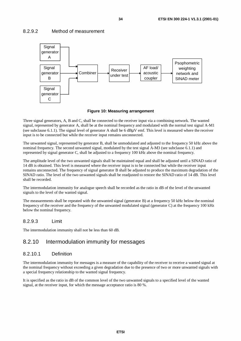
ETSI
ETSI EN 300 224-1 V1.3.1 (2001-01)34
8.2.9.2 Method of measurement
Signalgenerator
A
Signalgenerator
B
Signalgenerator
C
CombinerReceiverunder test
Psophometricweighting
network andSINAD meter
AF load/acousticcoupler
Figure 10: Measuring arrangement
Three signal generators, A, B and C, shall be connected to the receiver input via a combining network. The wantedsignal, represented by generator A, shall be at the nominal frequency and modulated with the normal test signal A-M1(see subclause 6.1.1). The signal level of generator A shall be 6 dBµV emf. This level is measured where the receiverinput is to be connected but while the receiver input remains unconnected.
The unwanted signal, represented by generator B, shall be unmodulated and adjusted to the frequency 50 kHz above thenominal frequency. The second unwanted signal, modulated by the test signal A-M3 (see subclause 6.1.1) andrepresented by signal generator C, shall be adjusted to a frequency 100 kHz above the nominal frequency.
The amplitude level of the two unwanted signals shall be maintained equal and shall be adjusted until a SINAD ratio of14 dB is obtained. This level is measured where the receiver input is to be connected but while the receiver inputremains unconnected. The frequency of signal generator B shall be adjusted to produce the maximum degradation of theSINAD ratio. The level of the two unwanted signals shall be readjusted to restore the SINAD ratio of 14 dB. This levelshall be recorded.
The intermodulation immunity for analogue speech shall be recorded as the ratio in dB of the level of the unwantedsignals to the level of the wanted signal.
The measurements shall be repeated with the unwanted signal (generator B) at a frequency 50 kHz below the nominalfrequency of the receiver and the frequency of the unwanted modulated signal (generator C) at the frequency 100 kHzbelow the nominal frequency.
8.2.9.3 Limit
The intermodulation immunity shall not be less than 60 dB.
8.2.10 Intermodulation immunity for messages
8.2.10.1 Definition
The intermodulation immunity for messages is a measure of the capability of the receiver to receive a wanted signal atthe nominal frequency without exceeding a given degradation due to the presence of two or more unwanted signals witha special frequency relationship to the wanted signal frequency.
It is specified as the ratio in dB of the common level of the two unwanted signals to a specified level of the wantedsignal, at the receiver input, for which the message acceptance ratio is 80 %.
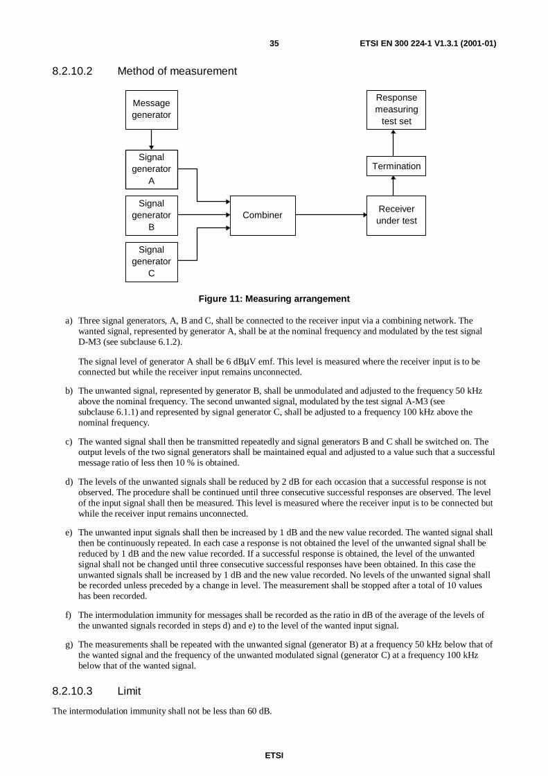
ETSI
ETSI EN 300 224-1 V1.3.1 (2001-01)35
8.2.10.2 Method of measurement
Messagegenerator
Signalgenerator
A
Signalgenerator
B
Signalgenerator
C
CombinerReceiverunder test
Responsemeasuring
test set
Termination
Figure 11: Measuring arrangement
a) Three signal generators, A, B and C, shall be connected to the receiver input via a combining network. Thewanted signal, represented by generator A, shall be at the nominal frequency and modulated by the test signalD-M3 (see subclause 6.1.2).
The signal level of generator A shall be 6 dBµV emf. This level is measured where the receiver input is to beconnected but while the receiver input remains unconnected.
b) The unwanted signal, represented by generator B, shall be unmodulated and adjusted to the frequency 50 kHzabove the nominal frequency. The second unwanted signal, modulated by the test signal A-M3 (seesubclause 6.1.1) and represented by signal generator C, shall be adjusted to a frequency 100 kHz above thenominal frequency.
c) The wanted signal shall then be transmitted repeatedly and signal generators B and C shall be switched on. Theoutput levels of the two signal generators shall be maintained equal and adjusted to a value such that a successfulmessage ratio of less then 10 % is obtained.
d) The levels of the unwanted signals shall be reduced by 2 dB for each occasion that a successful response is notobserved. The procedure shall be continued until three consecutive successful responses are observed. The levelof the input signal shall then be measured. This level is measured where the receiver input is to be connected butwhile the receiver input remains unconnected.
e) The unwanted input signals shall then be increased by 1 dB and the new value recorded. The wanted signal shallthen be continuously repeated. In each case a response is not obtained the level of the unwanted signal shall bereduced by 1 dB and the new value recorded. If a successful response is obtained, the level of the unwantedsignal shall not be changed until three consecutive successful responses have been obtained. In this case theunwanted signals shall be increased by 1 dB and the new value recorded. No levels of the unwanted signal shallbe recorded unless preceded by a change in level. The measurement shall be stopped after a total of 10 valueshas been recorded.
f) The intermodulation immunity for messages shall be recorded as the ratio in dB of the average of the levels ofthe unwanted signals recorded in steps d) and e) to the level of the wanted input signal.
g) The measurements shall be repeated with the unwanted signal (generator B) at a frequency 50 kHz below that ofthe wanted signal and the frequency of the unwanted modulated signal (generator C) at a frequency 100 kHzbelow that of the wanted signal.
8.2.10.3 Limit
The intermodulation immunity shall not be less than 60 dB.
ETSI
ETSI EN 300 224-1 V1.3.1 (2001-01)36
8.2.11 Blocking immunity or desensitization for analogue speech
8.2.11.1 Definition
The blocking immunity or desensitization for analogue speech is a measure of the capability of the receiver to receive awanted modulated signal at the nominal frequency without exceeding a given degradation due to the presence of anunwanted unmodulated high input signal, which is not a direct spurious frequency of the receiver under test.
It is specified as the ratio in dB of the level of the unwanted signal to a specified level of the wanted signal whichproduces through a psophometric weighting network a SINAD ratio of 14 dB (blocking immunity) or a power reductionof 3 dB in the receiver audio output power (desensitization).
8.2.11.2 Method of measurement
The measuring arrangement shown in figure 10 shall be used.
Two signal generators, A and B, shall be connected to the receiver input via a combining network. The wanted signal,represented by generator A, shall be at the nominal frequency and modulated by the test signal AM-1 (seesubclause 6.1.1). The signal level of generator A shall be 6 dBµV emf. This level is measured where the receiver inputis to be connected but while the receiver input remains unconnected.
The unwanted signal, represented by generator B, shall be at least 1 MHz away from the nominal frequency and thelevel shall be increased until a reduction of the receiver audio output power or a reduction of the SINAD ratio isobserved.
The level shall be kept constant and the frequency of the unwanted signal shall be varied over the range +1 MHz to+10 MHz and -1 MHz to -10 MHz relative to the nominal frequency of the receiver. The frequency at which thegreatest degradation occurs shall be noted, ensuring that it is not a spurious frequency response.
The level of the unwanted signal shall then be adjusted to give:
- a reduction of 3 dB in the receiver audio output power; or
- a reduction to 14 dB SINAD ratio at the receiver audio output, whichever occurs first.
This level shall be measured. This input level is measured where the receiver input is to be connected but while thereceiver input remains unconnected.
The blocking ratio or desensitization for analogue speech shall be recorded as the ratio in dB between the level of theunwanted signal to the level of the wanted signal, at the receiver input.
8.2.11.3 Limit
The blocking immunity shall not be less than 70 dB.
8.2.12 Blocking immunity or desensitization for messages
8.2.12.1 Definition
The blocking immunity or desensitization for messages is a measure of the capability of the receiver to receive a wantedmodulated signal at the nominal frequency without exceeding a given degradation due to the presence of an unwantedunmodulated high input signal, which is not a direct spurious frequency of the receiver under test.
It is specified as the ratio in dB of the level of the unwanted signal to a specified level of the wanted signal at thereceiver input for which the message acceptance ratio is 80 %.
ETSI
ETSI EN 300 224-1 V1.3.1 (2001-01)37
8.2.12.2 Method of measurement
The measuring arrangement shown in figure 10 shall be used.
a) Two signal generators A and B shall be connected to the receiver input via a combining network. The wantedsignal, represented by signal generator A, shall be at the nominal frequency of the receiver and shall have testmodulation D-M3.
Initially the unwanted signal, represented by the signal generator B, shall be switched off and the amplitude ofsignal generator A shall be adjusted to +6 dBµV emf. This level is measured where the receiver input is to beconnected but while the receiver input remains unconnected.
b) The wanted signal shall then be transmitted repeatedly and signal generator B shall be switched on. Theunwanted signal shall be unmodulated and its frequency shall be selected in the range +1 MHz ± 10 % relative tothe nominal frequency of the receiver. This frequency shall be one at which no spurious response occur. Thislevel shall be adjusted until a successful message ratio of less than 10 % is obtained.
c) The level of the unwanted signal shall be reduced by 2 dB for each occasion that a successful response is notobserved. The procedure shall be continued until three consecutive successful responses are observed. The levelof the input signal shall then be measured. This level is measured where the receiver input is to be connected butwhile the receiver input remains unconnected.
d) The unwanted input signal shall then be increased by 1 dB and the new value recorded. The wanted signal shallthen be continuously repeated. In each case a response is not obtained the level of the unwanted signal shall bereduced by 1 dB and the new value recorded. If a successful response is obtained, the level of the unwantedsignal shall not be changed until three consecutive successful responses have been obtained. In this case theunwanted signals shall be increased by 1 dB and the new value recorded. No levels of the unwanted signal shallbe recorded unless preceded by a change in level. The measurement shall be stopped after a total of 10 valueshave been recorded.
e) The measurements shall be repeated at a frequency of the unwanted signal selected in the range-1,0 MHz ± 10 % relative to the nominal frequency of the receiver.
f) The blocking level for messages is recorded as the lower value of the ratios in dB, of the two measurementsabove, of the average of the levels of the unwanted signal recorded in steps c) and d) to the level of the wantedsignal.
8.2.12.3 Limit
The blocking immunity shall not be less than 70 dB.
8.2.13 Spurious emissions
8.2.13.1 Definition
Spurious emissions are discrete radio frequency signals conveyed from the antenna socket by conduction or radiated bythe receiver.
They are specified as the power level of any discrete signal measured by the measuring device within the specifiedfrequency range.
8.2.13.2 Method of measurement
8.2.13.2.1 Conducted spurious components
The receiver input terminals shall be connected to a measuring receiver having an input impedance of 50 Ω and thereceiver under test shall be switched on.
The frequency of the measuring receiver shall be adjusted over the specified frequency range of 9 kHz to 4 GHz. Thefrequency and the absolute power level of each of the spurious components found shall be recorded.
ETSI
ETSI EN 300 224-1 V1.3.1 (2001-01)38
The measuring receiver used shall have sufficient dynamic range and sensitivity to achieve the required measurementaccuracy at the specified limit.
8.2.13.2.2 Radiated spurious components
On a test site, fulfilling the requirements of subclause 6.4, the sample shall be placed at the specified height on thesupport. The receiver shall be switched on.
The radiation of any spurious components shall be detected by the test antenna and receiver over the frequency range of25 MHz to 4 GHz.
At each frequency at which a component is detected, the sample shall be rotated to obtain maximum response and theeffective radiated power of that component determined by a substitution measurement.
The measurements shall be repeated with the test antenna in the orthogonal plane.
8.2.13.3 Limits
The power of any spurious component shall not exceed:
- 2 nW in the range 9 kHz to 1 GHz; and
- 20 nW in the range 1 GHz to 4 GHz.
9 Inductive loop systemsInductive loop systems are systems using frequencies in the Very Low Frequency (VLF) and LF range to transferinformation to the pocket receivers. A typical antenna used in these systems is a loop formed by a wire(s) within oraround the building or area to be covered.
9.1 Additional definitions for inductive systemscategories of emission: all classes of constant envelope modulation by code and speech are allowed, as well asmulti-carrier systems
loop frequency band: frequency range between 16 kHz and 146 kHz
artificial load: non-reactive non-radiating load equal to the nominal load specified by the manufacturer
test antenna: electrically screened loop or equivalent antenna, with which the magnetic component of the field can bemeasured
9.2 Loop transmitter requirements
9.2.1 Transmitter carrier power
9.2.1.1 Definition
The carrier power of the loop transmitter or amplifier is defined as the mean power delivered to an artificial load underspecified conditions of measurements, in the absence of modulation.
9.2.1.2 Measuring method
The transmitter shall be connected to an artificial load according to subclause 9.1 and the power delivered to thisartificial load shall be measured. The measurements shall be made under normal test conditions and extreme testconditions (extreme temperature and supply voltage simultaneously, see subclauses 5.2 and 5.3).

ETSI
ETSI EN 300 224-1 V1.3.1 (2001-01)39
9.2.1.3 Limit
Maximum output power under normal and extreme test conditions shall not exceed 20 W.
9.2.2 Range of operating frequencies
The range of operating frequencies shall be stated by the manufacturer.
9.2.2.1 Limits
The lowest operating frequency shall be greater than or equal to 16 + Fe + Fb/2 (in kHz).
The highest operating frequency shall be less than or equal to 146 - Fe - Fb/2 (in kHz).
Where:
Fe = frequency error in kHz as determined in subclause 9.2.2.2;
Fb = modulation bandwidth in kHz as determined in subclause 9.2.2.3.
For multi-carrier (unmodulated) systems the modulation bandwidth is assumed to be zero.
9.2.2.2 Frequency error
9.2.2.2.1 Definition
The frequency error of the transmitter system is the difference between the measured unmodulated carrier and thenominal frequency declared by the manufacturer.
9.2.2.2.2 Measuring method
The transmitter shall be connected to an artificial load according to subclause 9.1. The measurement shall be madeunder normal test conditions and extreme test conditions (extreme temperature and supply voltage simultaneously, seesubclauses 5.2 and 5.3). The carrier frequency shall be measured in the absence of modulation, for multi-carrier systemsa single carrier shall be selected. If it is not possible to obtain an unmodulated carrier, the carrier frequency shall bemeasured as follows:
- the transmitter shall be set to continuously produce the carrier frequency representing the "space" condition andthe carrier frequency shall be measured using a frequency counter;
- the measurement shall be repeated with the transmitter set to continuously produce the carrier frequencyrepresenting the "mark" condition;
- the unmodulated carrier frequency shall be obtained as the arithmetic mean of the two frequencies measuredabove.
9.2.2.2.3 Limits
The maximum frequency error shall be within ±1 % of the nominal frequency.
The maximum frequency error measured shall be used to determine the range of operating frequencies (seesubclause 9.2.2.1).
9.2.2.3 Modulation bandwidth
9.2.2.3.1 Definition
The modulation bandwidth of the transmitter is a measure for attenuation of the modulation products at a certain offsetfrom the nominal carrier frequency under defined conditions of modulation.
ETSI
ETSI EN 300 224-1 V1.3.1 (2001-01)40
9.2.2.3.2 Measuring method
The transmitter shall be operated at the carrier power determined in subclause 9.2.1 under normal test conditions. Thesignal to be measured shall be applied to the input of a measuring receiver at the appropriate level. The transmitter shallbe modulated with normal test signal D-M3 according to subclause 6.1.2 with normal coded test signal at the input levelspecified by the manufacturer. The measuring receiver shall be adjusted to a bandwidth of 100 Hz and a frequency spanthat is appropriate to measure the bandwidth at which the power is -30 dB relative to the unmodulated carrier.
Additionally where the transmitter has a speech facility the test shall be repeated using normal test signal A-M1according to subclause 6.1.1 but with the input level increased by 20 dB. The largest bandwidth measured shall berecorded.
9.2.2.3.3 Limit
No limit is specified, but the largest bandwidth measured shall be used to determine the range of operating frequencies(see subclause 9.2.2.1).
9.2.3 Spurious emissions
9.2.3.1 Definition
Spurious emissions are emissions at frequencies outside the loop frequency band as defined in subclause 9.1.
The level of spurious emissions shall be measured as:
a) the power delivered to an artificial load;
b) the field strength radiated by the cabinet and the structure of the transmitter.
9.2.3.2 Measuring methods
9.2.3.2.1 Method of measuring the power level
The unmodulated transmitter shall be connected through a "coupling device" to a measuring receiver. This "couplingdevice" shall or may have the following properties:
1) it shall provide a load to the loop which is equal to the nominal load specified by the manufacturer;
2) the load shall be configured to prevent ground loops;
3) it may include appropriate filters to provide overload protection for the measuring receiver.
The measurements shall be made over the frequency range of 9 kHz to 25 MHz, except the loop frequency band.
9.2.3.2.2 Method of measuring the field strength
On a suitable test site the transmitter shall be placed at a height of 1 m on a non-conducting support. The transmittershall be placed in the attitude in which it is normally used. An artificial load according to subclause 9.1 shall beconnected to the transmitter. A test antenna according to subclause 9.1 shall be placed at 3 m distance and 1 m heightand a measuring receiver shall be connected to it. The transmitter shall be switched on, if possible without modulation.Radiation of any spurious emission shall be measured over the frequency range of 9 kHz to 25 MHz (except the loopfrequency band). At each frequency at which a component is detected the transmitter shall be rotated through 360° inthe horizontal plane until the maximum signal is detected on the measuring receiver.
9.2.3.2.3 Method of measuring spurious radiation above 25 MHz
For method of measuring the spurious radiation above 25 MHz see subclause 7.5.2.
ETSI
ETSI EN 300 224-1 V1.3.1 (2001-01)41
9.2.3.3 Limits
a) Conducted emissions:
- 9 kHz to 16 kHz: 40 dB below carrier;
- 146 kHz to 1 MHz: ≤ 1 µW;
- 1 MHz to 25 MHz: ≤ 250 nW.
b) Radiated emissions below 25 MHz:
- 9 kHz to 16 kHz: descending from 53 dBµA/m to 48 dBµA/m;
- 146 kHz to 1 MHz: descending from 28,5 dBµA/m to 12 dBµA/m;
- 1 MHz to 25 MHz: descending from 12 dBµA/m to 2 dBµA/m.
The limit is decreasing linearly with the logarithm of the frequency. A graphical representation is given inannex D, figure D.1.
c) Radiated emissions above 25 MHz:
the measured values shall not exceed the limits for radiated emissions given in tables 5 and 6 in subclause 7.5.3.
9.3 Receiver requirements
9.3.1 Spurious emissions
9.3.1.1 Definition
Spurious emissions from receivers are emissions at frequencies outside the loop frequency band (see subclause 9.1),radiated from the chassis and case of the receiver. It is specified as the radiated power of a discrete signal.
9.3.1.2 Measuring method
a) For emissions below 25 MHz.
On a suitable test site the receiver shall be placed at a height of 1 m on a non-conducting support. The receivershall be placed in the position in which it is normally used. The test antenna according to subclause 9.1 shall beplaced at 3 m distance and 1 m height and a measuring receiver shall be connected to it.
The receiver shall be switched on. Radiation of any spurious emissions shall be measured over the frequencyrange of 9 kHz to 25 MHz (except the loop frequency band). At each frequency at which a component isdetected the receiver shall be rotated through 360° in the horizontal plane until the maximum signal is detectedon the measuring receiver.
b) For emissions above 25 MHz (see subclause 8.1.1.2).
9.3.1.3 Limits
The spurious components shall not exceed the following values at a distance of 3 m:
a) Radiated emissions below 25 MHz:
- 9 kHz to 16 kHz: descending from 41 dBµA/m to 36 dBµA/m;
- 146 kHz to 1 MHz: descending from 16,5 dBµA/m to 0 dBµA/m;
- 1 MHz to 25 MHz: descending from 0 dBµA/m to -10 dBµA/m.
The limit is decreasing linearly with the logarithm of the frequency.
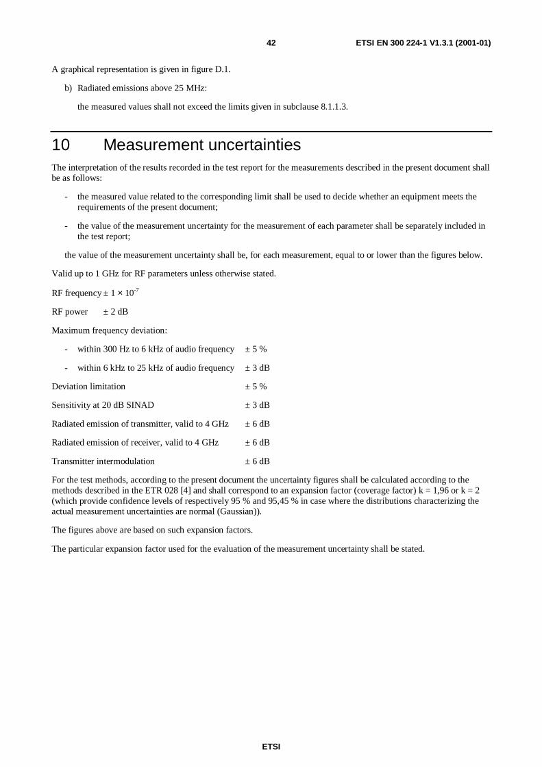
ETSI
ETSI EN 300 224-1 V1.3.1 (2001-01)42
A graphical representation is given in figure D.1.
b) Radiated emissions above 25 MHz:
the measured values shall not exceed the limits given in subclause 8.1.1.3.
10 Measurement uncertaintiesThe interpretation of the results recorded in the test report for the measurements described in the present document shallbe as follows:
- the measured value related to the corresponding limit shall be used to decide whether an equipment meets therequirements of the present document;
- the value of the measurement uncertainty for the measurement of each parameter shall be separately included inthe test report;
the value of the measurement uncertainty shall be, for each measurement, equal to or lower than the figures below.
Valid up to 1 GHz for RF parameters unless otherwise stated.
RF frequency ± 1 × 10⁻⁷
RF power ± 2 dB
Maximum frequency deviation:
- within 300 Hz to 6 kHz of audio frequency ± 5 %
- within 6 kHz to 25 kHz of audio frequency ± 3 dB
Deviation limitation ± 5 %
Sensitivity at 20 dB SINAD ± 3 dB
Radiated emission of transmitter, valid to 4 GHz ± 6 dB
Radiated emission of receiver, valid to 4 GHz ± 6 dB
Transmitter intermodulation ± 6 dB
For the test methods, according to the present document the uncertainty figures shall be calculated according to themethods described in the ETR 028 [4] and shall correspond to an expansion factor (coverage factor) k = 1,96 or k = 2(which provide confidence levels of respectively 95 % and 95,45 % in case where the distributions characterizing theactual measurement uncertainties are normal (Gaussian)).
The figures above are based on such expansion factors.
The particular expansion factor used for the evaluation of the measurement uncertainty shall be stated.
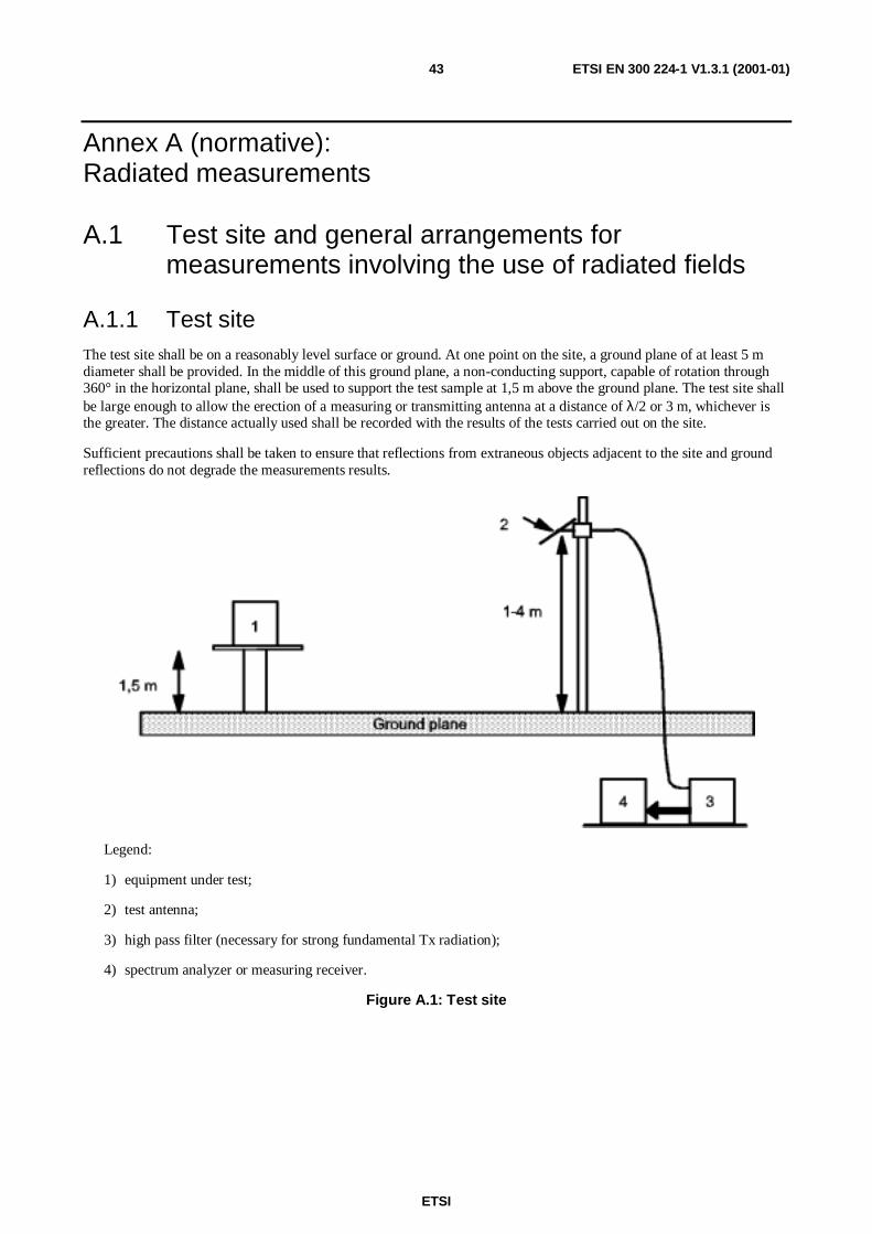
ETSI
ETSI EN 300 224-1 V1.3.1 (2001-01)43
Annex A (normative):Radiated measurements
A.1 Test site and general arrangements formeasurements involving the use of radiated fields
A.1.1 Test siteThe test site shall be on a reasonably level surface or ground. At one point on the site, a ground plane of at least 5 mdiameter shall be provided. In the middle of this ground plane, a non-conducting support, capable of rotation through360° in the horizontal plane, shall be used to support the test sample at 1,5 m above the ground plane. The test site shallbe large enough to allow the erection of a measuring or transmitting antenna at a distance of λ/2 or 3 m, whichever isthe greater. The distance actually used shall be recorded with the results of the tests carried out on the site.
Sufficient precautions shall be taken to ensure that reflections from extraneous objects adjacent to the site and groundreflections do not degrade the measurements results.
Legend:
1) equipment under test;
2) test antenna;
3) high pass filter (necessary for strong fundamental Tx radiation);
4) spectrum analyzer or measuring receiver.
Figure A.1: Test site

ETSI
ETSI EN 300 224-1 V1.3.1 (2001-01)44
A.1.1.1 Standard position
The standard position on all test sites, except for equipment which is intended to be worn on a person, shall be asfollows:
- for equipment with an integral antenna; it shall be placed in the position closest to normal use as declared by themanufacturer;
- for equipment with a rigid external antenna; the antenna shall be vertical;
- for equipment with non-rigid external antenna, the antenna shall be extended vertically upwards by a non-conducting support.
A.1.2 Test antennaThe test antenna is used to detect the radiation from both the test sample and the substitution antenna, when the site isused for radiation measurements; where necessary, it is used as a transmitting antenna, when the site is used for themeasurement of receiver characteristics.
This antenna is mounted on a support such as to allow the antenna to be used in either horizontal or vertical polarizationand for the height of its centre above ground to be varied over the range 1 to 4 m. Preferably a test antenna withpronounced directivity should be used. The size of the test antenna along the measurement axis shall not exceed 20 % ofthe measuring distance.
For receiver and transmitter radiation measurements, the test antenna is connected to a measuring receiver, capable ofbeing tuned to any frequency under investigation, and of measuring accurately the relative levels of signals at its input.For receiver radiated sensitivity measurements the test antenna is connected to a signal generator.
A.1.3 Substitution antennaWhen measuring in the frequency range up to 1 GHz the substitution antenna shall be a λ/2 dipole, resonant at thefrequency under consideration, or a shortened dipole, calibrated to a λ/2 dipole. When measuring in the frequency rangeabove 4 GHz a horn radiator shall be used. For measurements between 1 and 4 GHz either a λ/2 dipole or a hornradiator may be used. The centre of this antenna shall coincide with the reference point of the test sample it hasreplaced. This reference point shall be the volume centre of the sample when its antenna is mounted inside the cabinet,or the point where an external antenna is connected to the cabinet.
The distance between the lower extremity of the dipole and the ground shall be at least 0,3 m.
The substitution antenna shall be connected to a calibrated signal generator when the site is used for spurious radiationmeasurements and transmitter effective radiated power measurements. The substitution antenna shall be connected to acalibrated measuring receiver when the site is used for the measurement of receiver sensitivity.
The signal generator and the receiver shall be operated at the frequencies under investigation and shall be connected tothe antenna through suitable matching and balancing networks.
NOTE: The gain of a horn antenna is generally expressed relative to an isotropic radiator by the hornmanufacturer's data. This data should be corrected and referenced to that of a λ/2 dipole. It is assumedthat the gain of a λ/2 dipole relative to an isotropic radiator is + 2,2 dBi.
Therefore, the calculation is as follows:
erp = Ps-C+A,
where:
- Ps = Power level of the signal generator;
- C = Coaxial cable loss (signal generator to antenna);
- A = Antenna gain (relative to λ/2 dipole) = dBd;
- dBd = dBi - 2,2.

ETSI
ETSI EN 300 224-1 V1.3.1 (2001-01)45
A.1.4 Optional additional indoor siteWhen the frequency of the signal being measured is greater than 80 MHz, use may be made of an indoor site. If thisalternative site is used, this shall be recorded in test reports.
The measurement site may be a laboratory room with a minimum area of 6 m by 7 m and at least 2,7 m in height.
Apart from the measuring apparatus and the operator, the room shall be as free as possible from reflecting objects otherthan the walls, floor and ceiling.
The potential reflections from the wall behind the equipment under test are reduced by placing a barrier of absorbentmaterial in front of it. The corner reflector around the test antenna is used to reduce the effect of reflections from theopposite wall and from the floor and ceiling in the case of horizontally polarized measurements. Similarly, the cornerreflector reduces the effects of reflections from the side walls for vertically polarized measurements. For the lower partof the frequency range (below approximately 175 MHz) no corner reflector or absorbent barrier is needed. For practicalreasons, the λ/2 antenna in figure A.2 may be replaced by an antenna of constant length, provided that this length isbetween λ/4 and λ at the frequency of measurement and the sensitivity of the measuring system is sufficient. In thesame way the distance of λ/2 to the apex may be varied.
The test antenna, measuring receiver, substitution antenna and calibrated signal generator are used in a way similar tothat of the general method.
To ensure that errors are not caused by the propagation path approaching the point at which phase cancellation betweendirect and the remaining reflected signals occurs, the substitution antenna shall be moved through a distance of ±0,10 min the direction of the test antenna as well as in the two directions perpendicular to this first direction.
If these changes of distance cause a signal change of greater than 2 dB, the test sample shall be re-sited until a change ofless than 2 dB is obtained.
Figure A.2: Indoor site arrangement (shown for horizontal polarization)
A.2 Guidance on the use of radiation test sitesFor measurements involving the use of radiated fields, use may be made of a test site in conformity with therequirements of clause A.1. When using such a test site, the following conditions should be observed to ensureconsistency of measuring results.
ETSI
ETSI EN 300 224-1 V1.3.1 (2001-01)46
A.2.1 Measuring distanceEvidence indicates that the measuring distance is not critical and does not significantly affect the measuring results,provided that the distance is not less than λ/2 at the frequency of measurement and the precautions described in thisannex are observed. Measuring distances of 3 m, 5 m, 10 m and 30 m are in common use in European test laboratories.
A.2.2 Test antennaDifferent types of test antenna may be used, since performing substitution measurements reduces the effect of the errorson the measuring results.
Height variation of the test antenna over a range of 1 to 4 m is essential in order to find the point at which the radiationis a maximum.
Height variation of the test antenna may not be necessary at the lower frequencies, below approximately 100 MHz.
A.2.3 Substitution antennaVariations in the measuring results may occur with the use of different types of substitution antenna at the lowerfrequencies, below approximately 80 MHz.
Where a shortened dipole antenna is used at these frequencies, details of the type of antenna used shall be included withthe results of the tests carried out on the site. Correction factors shall be taken into account when shortened dipoleantennas are used.
A.2.4 Artificial antennaThe dimensions of the artificial antenna used during radiated measurements should be small in relation to the sampleunder test.
Where possible, a direct connection shall be used between the artificial antenna and the test sample.
In cases where it is necessary to use a connecting cable, precautions shall be taken to reduce the radiation from thiscable by, for example, the use of ferrite cores or double screened cables.
A.2.5 Auxiliary cablesThe position of auxiliary cables (power supply and microphone cables, etc.) which are not adequately decoupled maycause variations in the measuring results. In order to get reproducible results, cables and wires of auxiliaries shall bearranged vertically downwards (through a hole in the non conducting support).
A.2.6 Acoustic measuring arrangementWhen carrying out measurements of the maximum usable sensitivity (radiated) of the receiver, the audio output shall bemonitored by acoustically coupling the audio signal from the receiver loudspeaker/transducer to the test microphone.On the radiation test site, all conducting materials shall be placed below the ground surface and the acoustic signalconveyed from the receiver to the test microphone via a non-conducting acoustic pipe.
The acoustic pipe shall have an appropriate length, an inner diameter of 6 mm and a wall thickness of 1,5 mm. A plasticfunnel of a diameter corresponding to the receiver loudspeaker/transducer shall be attached to the receiver surfacecentred in front of the receiver loudspeaker/transducer. The plastic funnel shall be very soft at the attachment point tothe receiver in order to avoid mechanical resonance. The narrow end of the plastic funnel shall be connected to the oneend of the acoustic pipe and the test microphone to the other.
ETSI
ETSI EN 300 224-1 V1.3.1 (2001-01)47
A.3 Further optional alternative indoor site using ananechoic chamber
For radiation measurements when the frequency of the signals being measured is greater than 30 MHz, use may bemade of an indoor site consisting of a well-shielded anechoic chamber simulating a free space environment. If such achamber is used, this shall be recorded in test reports.
The test antenna, test receiver, substitution antenna and calibrated signal generator shall be used in a way similar to thatof the general method, given in clause A.1. In the range between 30 MHz to 100 MHz some additional calibration maybe necessary.
An example of a typical measurement site may be an electrically shielded anechoic chamber being 10 m long, 5 mbroad and 5 m high.
Walls and ceiling are coated with RF absorbers of 1 m height.
The base is covered with absorbing material 1 m thick, and a wooden floor, able to carry test equipment and operators.
A measuring distance of 3 to 5 m in the long middle axis of the chamber can be used for measurements up to12,75 GHz. The construction of the anechoic chamber is described in the following subclauses.
A.3.1 Example of the construction of a shielded anechoicchamber
Free-field measurements can be simulated in a shielded measuring chamber where the walls are coated with RFabsorbers.
Figure A.3 shows the requirements for shielding loss and wall return loss of such a room.
As dimensions and characteristics of usual absorber materials are critical below 100 MHz (height of absorbers < 1 m,reflection attenuation < 20 dB) such a room is preferably suitable for measurements above 100 MHz.
Figure A.4 shows the construction of a shielded measuring chamber having a base area of 5 m by 10 m and a height of5 m.
Ceilings and walls are coated with pyramidal formed RF absorbers approximately 1 m high. The base is covered withabsorbers above which is constructed a non-conducting sub-floor, or with special ground floor absorbers.
The available internal dimensions of the room are 3 m by 8 m by 3 m, so that a measuring distance of maximum 5 mlength in the middle axis of this room is available.
At 100 MHz the measuring distance can be extended up to a maximum of 2 wavelengths.
The floor absorbers reject floor reflections so that the antenna height need not be changed and floor reflectioninfluences need not be considered.
All measuring results can therefore be checked with simple calculations and the measuring tolerances have the smallestpossible values due to the simple measuring configuration.
For special measurements it would be necessary to re-introduce floor reflections. Therefore the floor absorbers arecovered with metal plates or metallic nets instead.
A.3.2 Influence of parasitic reflections in anechoic chambersFor free-space propagation in the far field the correlation E=Eo(Ro/R) is valid for the dependence of the field strength Eon the distance R, whereby Eo is the reference field strength at the reference distance Ro.
It is useful to use just this correlation for comparison measurements, as all constants are eliminated with the ratio andneither cable attenuation, nor antenna mismatch, nor antenna dimensions are of importance.
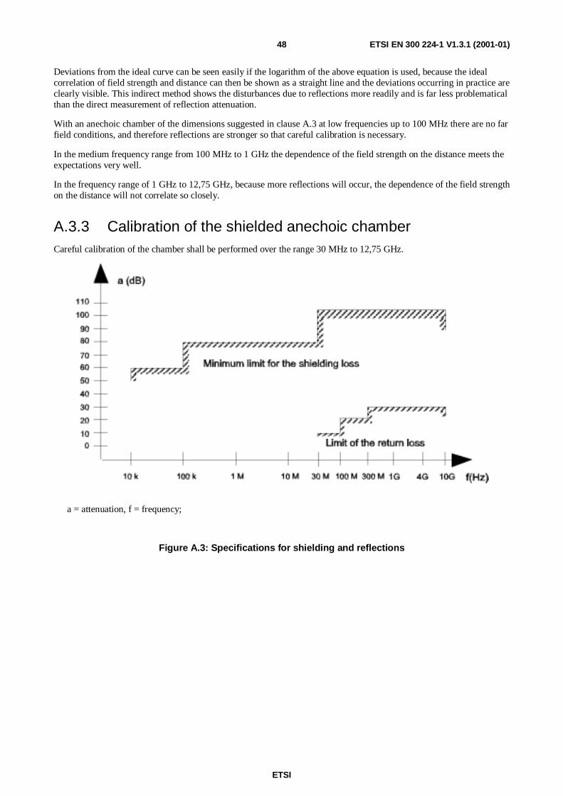
ETSI
ETSI EN 300 224-1 V1.3.1 (2001-01)48
Deviations from the ideal curve can be seen easily if the logarithm of the above equation is used, because the idealcorrelation of field strength and distance can then be shown as a straight line and the deviations occurring in practice areclearly visible. This indirect method shows the disturbances due to reflections more readily and is far less problematicalthan the direct measurement of reflection attenuation.
With an anechoic chamber of the dimensions suggested in clause A.3 at low frequencies up to 100 MHz there are no farfield conditions, and therefore reflections are stronger so that careful calibration is necessary.
In the medium frequency range from 100 MHz to 1 GHz the dependence of the field strength on the distance meets theexpectations very well.
In the frequency range of 1 GHz to 12,75 GHz, because more reflections will occur, the dependence of the field strengthon the distance will not correlate so closely.
A.3.3 Calibration of the shielded anechoic chamberCareful calibration of the chamber shall be performed over the range 30 MHz to 12,75 GHz.
a = attenuation, f = frequency;
Figure A.3: Specifications for shielding and reflections
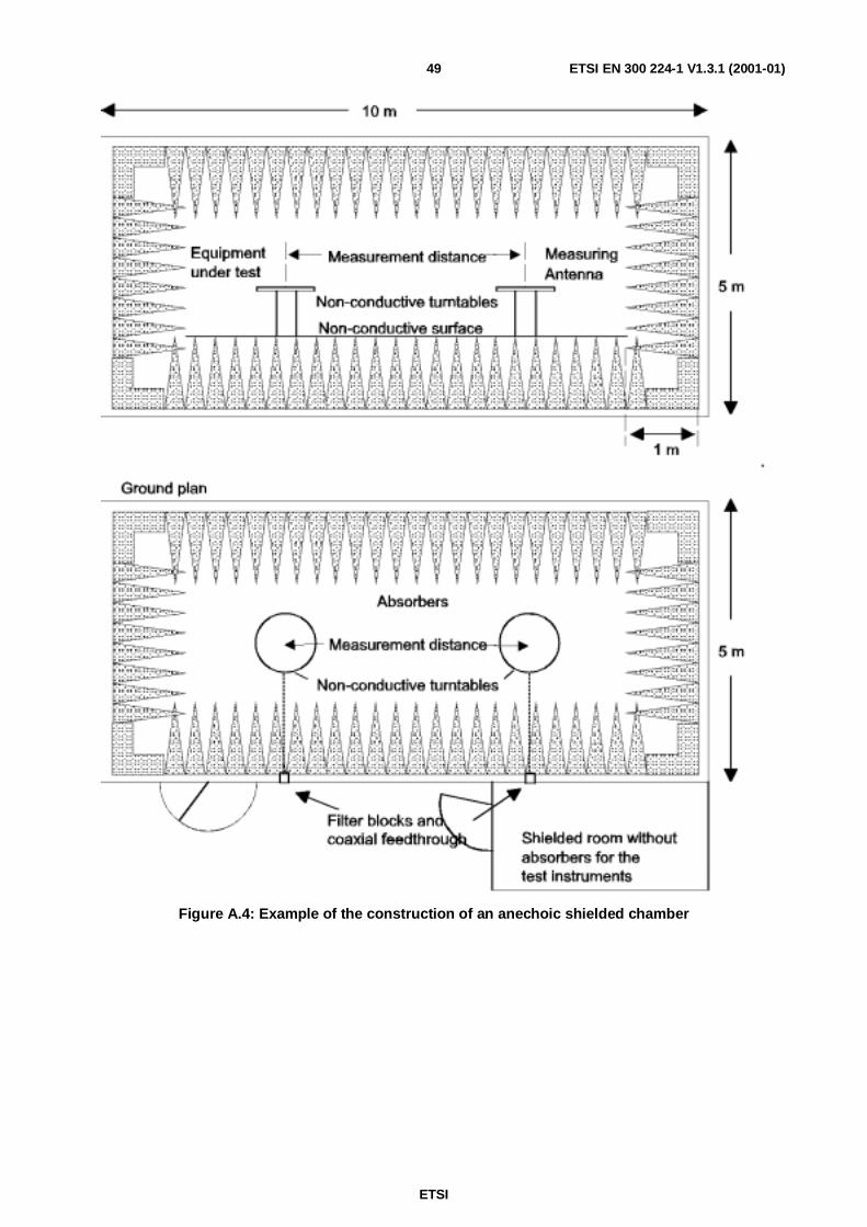
ETSI
ETSI EN 300 224-1 V1.3.1 (2001-01)49
Figure A.4: Example of the construction of an anechoic shielded chamber
ETSI
ETSI EN 300 224-1 V1.3.1 (2001-01)50
Annex B (normative):Support for pocket equipmentThis annex is not applicable for inductive loop systems.
For equipment operating at frequencies up to 50 MHz the support consists of a plastic tube, which is filled with saltwater (9 g of NaCl per litre). The tube shall have a length of 1,5 m and an internal diameter of 10 ± 0,5 cm. The upperend of the tube is closed by a metal plate with a diameter of 15 cm, which is in contact with the water. To meet therequirements for equipment with a rigid outside antenna (the antenna has to be in a vertical position during themeasurement) the metal plate shall, if necessary, be prepared in such a way that a second hinged metal plate of 10 × 15cm can be fastened to its narrow side. It shall be possible to change the supporting point of the hinged metal plate as faras the centre. The position of the hinged metal plate shall be adjustable within 0° to 90° with respect to the lower metalplate.
The sample shall be fastened in such a way that:
a) the centre of its largest area rests on the revolving metal plate; and
b) this centre, for its part, is located above the centre of the lower metal plate by changing the supporting point ofthe revolving plate.
In the case of samples, whose largest area is smaller than 10 cm × 15 cm, the centre of the sample shall (deviating frompoint a) be so changed in its longitudinal axis, that the antenna base is at the edge outside the metal plate.
For equipment operating on frequencies above 50 MHz this support shall be non-conductive.
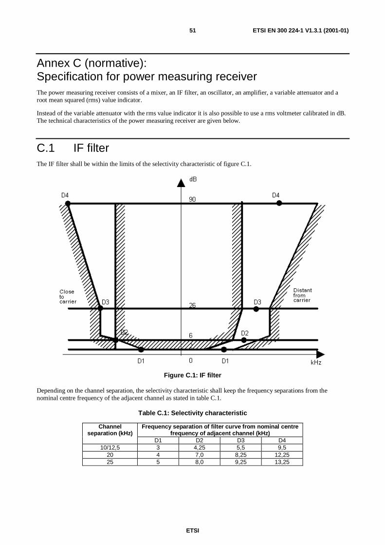
ETSI
ETSI EN 300 224-1 V1.3.1 (2001-01)51
Annex C (normative):Specification for power measuring receiverThe power measuring receiver consists of a mixer, an IF filter, an oscillator, an amplifier, a variable attenuator and aroot mean squared (rms) value indicator.
Instead of the variable attenuator with the rms value indicator it is also possible to use a rms voltmeter calibrated in dB.The technical characteristics of the power measuring receiver are given below.
C.1 IF filterThe IF filter shall be within the limits of the selectivity characteristic of figure C.1.
Figure C.1: IF filter
Depending on the channel separation, the selectivity characteristic shall keep the frequency separations from thenominal centre frequency of the adjacent channel as stated in table C.1.
Table C.1: Selectivity characteristic
Channelseparation (kHz)
Frequency separation of filter curve from nominal centrefrequency of adjacent channel (kHz)
D1 D2 D3 D410/12,5 3 4,25 5,5 9,5
20 4 7,0 8,25 12,2525 5 8,0 9,25 13,25
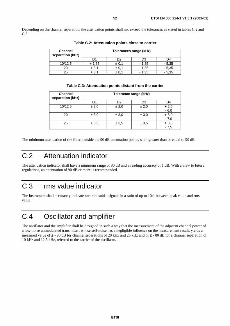
ETSI
ETSI EN 300 224-1 V1.3.1 (2001-01)52
Depending on the channel separation, the attenuation points shall not exceed the tolerances as stated in tables C.2 andC.3.
Table C.2: Attenuation points close to carrier
Channelseparation (kHz)
Tolerances range (kHz)
D1 D2 D3 D410/12,5 + 1,35 ± 0,1 - 1,35 - 5,35
20 + 3,1 ± 0,1 - 1,35 - 5,3525 + 3,1 ± 0,1 - 1,35 - 5,35
Table C.3: Attenuation points distant from the carrier
Channelseparation (kHz)
Tolerance range (kHz)
D1 D2 D3 D410/12,5 ± 2,0 ± 2,0 ± 2,0 + 2,0
- 6,020 ± 3,0 ± 3,0 ± 3,0 + 3,0
- 7,025 ± 3,5 ± 3,5 ± 3,5 + 3,5
- 7,5
The minimum attenuation of the filter, outside the 90 dB attenuation points, shall greater than or equal to 90 dB.
C.2 Attenuation indicatorThe attenuation indicator shall have a minimum range of 80 dB and a reading accuracy of 1 dB. With a view to futureregulations, an attenuation of 90 dB or more is recommended.
C.3 rms value indicatorThe instrument shall accurately indicate non-sinusoidal signals in a ratio of up to 10:1 between peak value and rmsvalue.
C.4 Oscillator and amplifierThe oscillator and the amplifier shall be designed in such a way that the measurement of the adjacent channel power ofa low-noise unmodulated transmitter, whose self-noise has a negligible influence on the measurement result, yields ameasured value of ≤ - 90 dB for channel separations of 20 kHz and 25 kHz and of ≤ - 80 dB for a channel separation of10 kHz and 12,5 kHz, referred to the carrier of the oscillator.
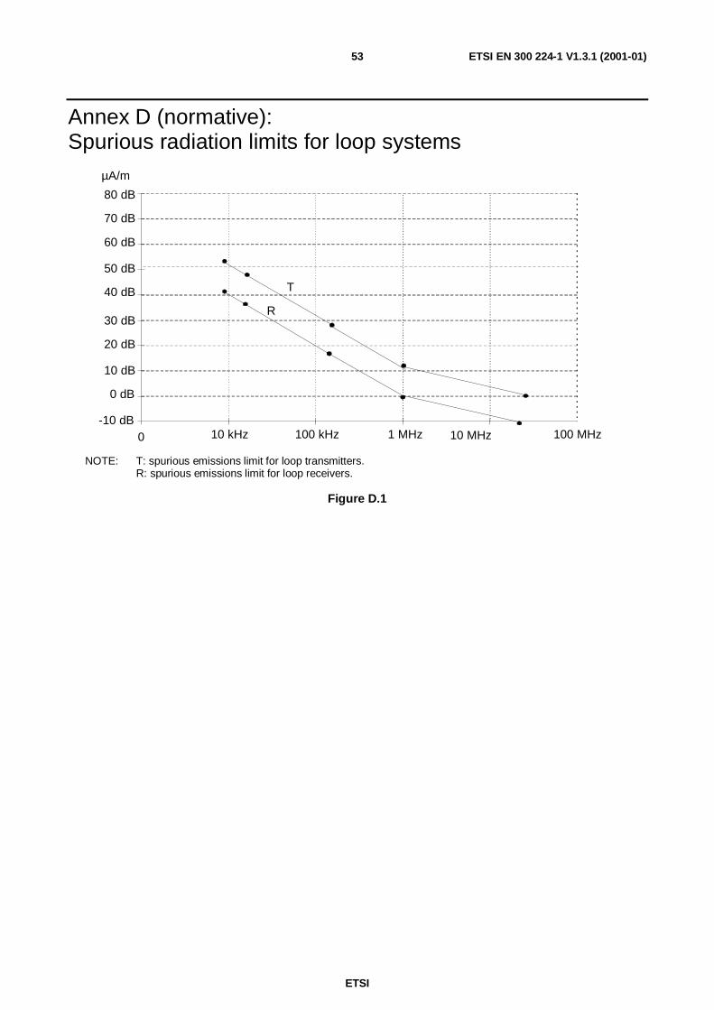
ETSI
ETSI EN 300 224-1 V1.3.1 (2001-01)53
Annex D (normative):Spurious radiation limits for loop systems
80 dB
70 dB
60 dB
50 dB
40 dB
30 dB
20 dB
10 dB
0 dB
-10 dB
T
R
10 kHz 100 kHz 1 MHz 10 MHz 100 MHz0
µA/m
NOTE: T: spurious emissions limit for loop transmitters.R: spurious emissions limit for loop receivers.
Figure D.1
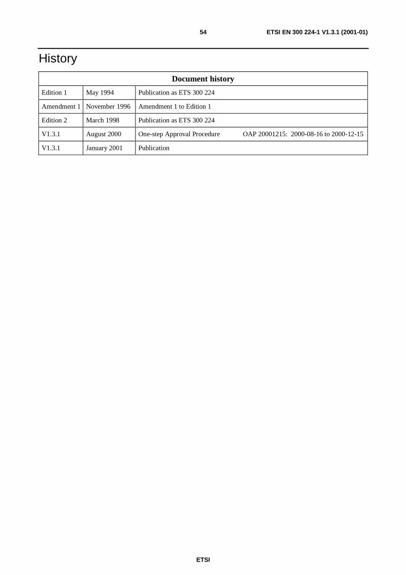
ETSI
ETSI EN 300 224-1 V1.3.1 (2001-01)54
History
Document history
Edition 1 May 1994 Publication as ETS 300 224
Amendment 1 November 1996 Amendment 1 to Edition 1
Edition 2 March 1998 Publication as ETS 300 224
V1.3.1 August 2000 One-step Approval Procedure OAP 20001215: 2000-08-16 to 2000-12-15
V1.3.1 January 2001 Publication