Embed Size (px)
Citation preview
www.irishrail.ie
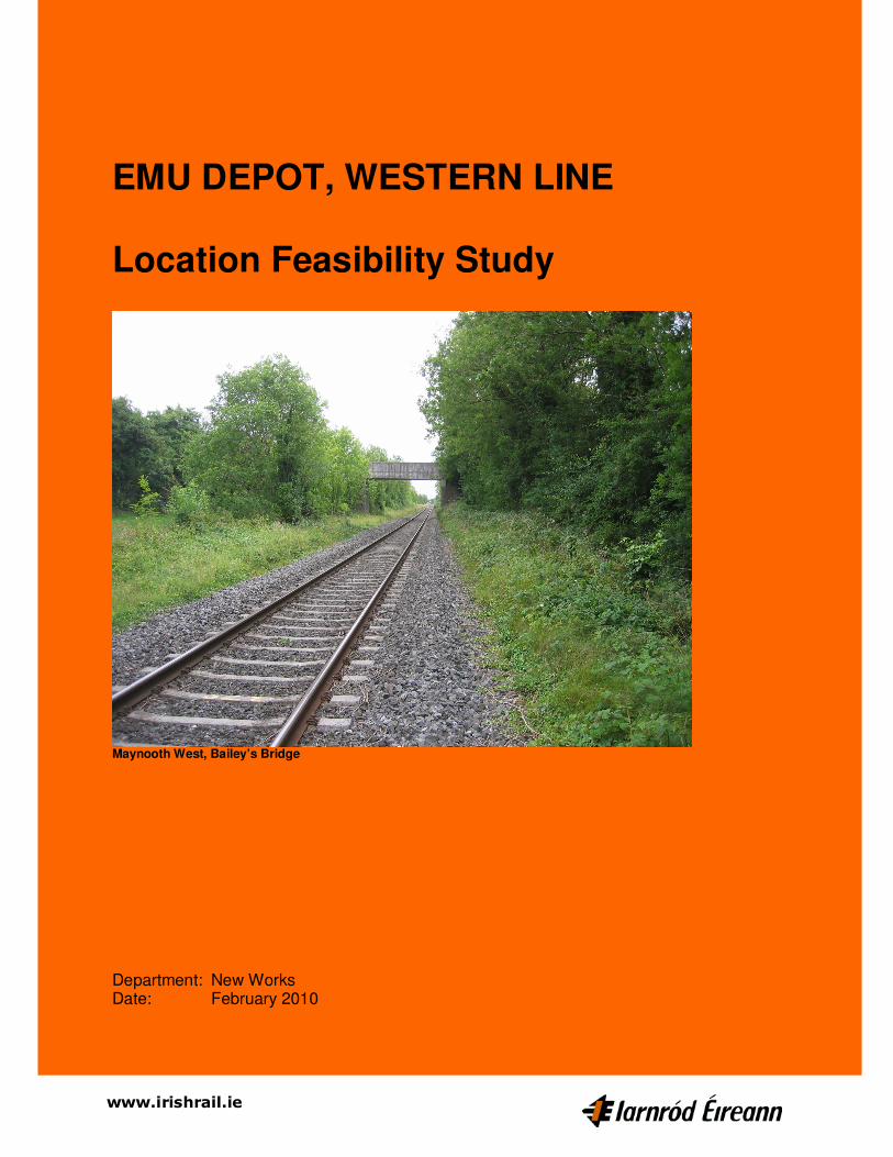
EMU DEPOT, WESTERN LINE Location Feasibility Study
Maynooth West, Bailey’s Bridge
Department: New Works Date: February 2010
EMU Depot, Western Line
Feasibility Study
2 of 37
Table of Contents Executive Summary........................................................................................................ 3
1 Introduction .............................................................................................................. 5
1.1 Objective.............................................................................................................. 5
1.2 Proposal .............................................................................................................. 5
1.3 Project Sponsor ................................................................................................... 5
1.4 Executing Department ......................................................................................... 5
1.5 Business Case ..................................................................................................... 5
1.6 History To-date .................................................................................................... 6
1.7 Current Position ................................................................................................... 6
1.8 Board Approval .................................................................................................... 6
2 Feasibility Study....................................................................................................... 7
2.1 Client Requirement Specification ......................................................................... 7
2.2 Topographical surveys ........................................................................................ 7
2.3 Determination of Track Layouts ........................................................................... 7
2.4 Property Requirements ........................................................................................ 7
2.5 Environmental Impact Review ............................................................................. 7
3 Site Options .............................................................................................................. 9
3.1 Option 1: McLoughlin Canal Bridge at 21 ¼ M.P. west of Kilcock ..................... 10
3.2 Option 2: Bailey Bridge at 16 ¾ M.P. west of Maynooth .................................... 11
3.3 Option 3: Collins Bridge at 9 ¼ M.P. east of Leixlip ........................................... 12
4 Cost Estimation ...................................................................................................... 13
4.1 Site Comparison Table ...................................................................................... 13
4.2 Main Contract Cost Estimate ............................................................................. 14
4.3 Overall Cost Estimate ........................................................................................ 15
4.4 Capital Cost Estimate Summary ........................................................................ 16
5 Risk Assessment ................................................................................................... 17
5.1 Attendees .......................................................................................................... 17
5.2 Agenda .............................................................................................................. 17
5.3 Merits and de-merits .......................................................................................... 18
5.4 Relative Value ................................................................................................... 19
5.5 Recommendation .............................................................................................. 20
6 Procuring and Phasing the Project ...................................................................... 20
6.1 Procurement ...................................................................................................... 20
6.2 Phasing ............................................................................................................. 21
6.3 Proposed Timescales & Milestone Dates .......................................................... 21
7 APPENDICES .......................................................................................................... 22
7.1 APPENDIX A ..................................................................................................... 23
Client Requirement Specification ................................................................................ 23
Distribution List Mr AR Fearn CEO, Iarnród Éireann Mr P Verster Chief Mechanical Engineer, Iarnród Éireann Mr B Kenny Manager Corporate Communications, Iarnród Éireann Mr M Reidy Manager Strategic & Business Planning, Iarnród Éireann
EMU Depot, Western Line
Feasibility Study
3 of 37
Executive Summary
The objective of this report is to undertake a feasibility study to review the three proposed locations for a new depot west of Dublin and recommend the best site. Consider, with stakeholder involvement, a holistic approach to the current parking constraints of Maynooth station. Determine cost estimates for the whole project, and obtain funding authorisation to further develop the project. The Project Sponsor for the project is the Chief Mechanical Engineer who is responsible for the business case and for ensuring that the Customer Requirement Specification is clearly defined by all project stakeholders. The executing department is the New Works Department who has the responsibility for delivering the project. The business case is driven by the proposed expansion of the EMU fleet in the Greater Dublin Area. This includes the electrification on the Maynooth, Kildare and Drogheda lines, the building of the Interconnector Tunnel and is also supported by the proposed re-signalling of the northern and Maynooth lines. Currently the EMU fleet comprising 176 vehicles is serviced at Fairview Depot in Dublin. This depot has very limited options for expansion. The present EMU fleet maintenance facilities have no dedicated wheel lathe and also cannot lift 4-piece units to carry out heavy maintenance activities without the uncoupling of train sets. The CME recently commissioned an external consultant, together with CIE Group Property, to identify several potential sites for this depot all west of Connolly Station, Dublin. Three sites were identified to be investigated further. The three preferred depot locations identified for further examination in this study are:- Option 1: McLoughlin Canal Bridge at 21 ¼ M.P. Option 2: Bailey Bridge at 16 ¾ M.P. Option 3: Collins Bridge at 9 ¼ M.P. The Client Requirement Specification for the proposed EMU Depot was developed during the project and the final version is appended A considerable amount of time was spent in determining the best possible track layout for each of the sites. A dead-end depot was specifically not preferred by the client. Attention was paid to the client’s requirement that the trains run through the proposed train wash as an initial activity on entering the depot. Also, the provision of an adequate receiving road for the mainline trains entering the depot area was a high priority. The number of shunting movements before, during and after servicing was considered. The land ownership of the various sites was determined as far as possible together with planning searches. CIE owns none of the three sites. An estimate of permanent land take was determined. Using Port Laoise Depot as the benchmark, the three sites were compared by initially measuring from the preliminary layout designs. As part of the Value Management process the respective Main D&B Contract element was estimated for the three sites, again using Port Laoise Depot cost as a basis for this determination. An overall Cost Estimate of all the design and construction estimates was determined for each of the respective sites.
EMU Depot, Western Line
Feasibility Study
4 of 37
A Risk Management Workshop was carried out on 21st April 2009 at Inchicore Training School. All interested and effected staff attended the workshop. The conclusion of the Value Management exercise was that the Maynooth West site gave the best relative value and is therefore the preferred site. Should the Business Case be supportive of the case to build a new EMU Depot it is assumed that it will take three years to obtain the necessary funding, execute procurement processes, planning, design and tender phases of the project. Then it is estimated that the construction of the enabling works and depot will take another four years. Based on this programme the estimated total escalated cost will be circa €210M, excluding rolling stock and the station. It is proposed that the Depot be built in phases; namely: Railway Order include whole scheme design up to tender stage Q2/’10 - Q2/’13 Phase 1 Land Purchase of whole site Q2/’13 - Q3/’17 Enabling Works: ESB diversions, canal over bridge & access road Site Clearance & drainage
Build 8 car long depot Build half yard track; signalling and electrification Electrify existing single mainline from Maynooth
Two mainline connections Phase 2 Complete yard trackwork and extend main building (Medium term) Double mainline track from Maynooth incl. signalling and electrification
Add one mainline connection Add diesel fuel facility Phase 3 Maynooth West Station (carpark built in phases) (Long term) It is the conclusion of this feasibility study that the Maynooth West site gives the best relative value and is therefore the preferred site to be further developed. Should the project business case be supportive it is recommended that the traditional process of design to Railway Order Stage and then design to tender for the design & build construction stage be followed as per the Port Laoise Depot project.
EMU Depot, Western Line
Feasibility Study
5 of 37
1 Introduction
1.1 Objective
The objective of this report is to undertake a feasibility study to: • Review the three proposed locations for a new depot west of Dublin and recommend the
best site. • Consider, with stakeholder involvement, a holistic approach to the current parking
constraints of Maynooth station. • Determine cost estimates for the whole project, and • Obtain funding authorisation to further develop the project
1.2 Proposal
In order to achieve its objectives this proposal needs to include the following activities:- • Determine the Client Requirement Specification • Carry out topographical surveys of the sites to be investigated • Determine best track layout(s) of the various depot sites • Carry out preliminary designs and determine cost estimates of the given site options • Carry out Value management and Risk Workshops to determine the most suitable
location for the depot • To carry out land ownership and planning searches and recommend the best property
acquisition strategy together with comprehensive cost estimates • Determine draft timetables and maintenance links to proposed depot using modelling of
operational network. This proposal will comply with the Department of Transport action plan produced to support the Disability Equality Bill 2004.
1.3 Project Sponsor
The Project Sponsor for the project is the Chief Mechanical Engineer who is responsible for the business case and for ensuring that the Customer Requirement Specification is clearly defined by all project stakeholders.
1.4 Executing Department
The executing department is the New Works Department who has the responsibility for delivering the project.
1.5 Business Case
The business case is driven by the proposed expansion of the EMU fleet in the Greater Dublin Area. This includes the electrification on the Maynooth, Kildare and Drogheda lines, the building of the Interconnector Tunnel and is also supported by the proposed re-signalling of the northern and Maynooth lines.
EMU Depot, Western Line
Feasibility Study
6 of 37
The procurement of new multiple unit fleets was initially due to be tendered at the end of March 2008 and contracts were expected to be executed in the 4th Quarter 2008. The proposed depot is required to conduct maintenance exams on this expanded EMU fleet that will be operating in the greater Dublin Area. A provision has been made for this proposed depot in Transport 21.
1.6 History To-date
Currently the EMU fleet comprising 176 vehicles is serviced at Fairview Depot in Dublin. This depot has very limited options for expansion. The present EMU fleet maintenance facilities have no dedicated wheel lathe and also cannot lift 4-piece units to carry out heavy maintenance activities without the uncoupling of train sets. The CME recently commissioned an external consultant, together with CIE Group Property, to identify several potential sites for this depot all west of Connolly Station, Dublin. Three sites were identified to be investigated further.
1.7 Current Position
The three preferred depot locations identified for further examination in this study are:- Option 1: McLoughlin Canal Bridge at 21 ¼ M.P. Option 2: Bailey Bridge at 16 ¾ M.P. Option 3: Collins Bridge at 9 ¼ M.P.
1.8 Board Approval
The approval of the Board of Iarnród Éireann was granted in April 2008 for the expenditure of €150K to carry out a feasibility study to determine the best site of the three preferred locations for the new Electric Multiple Unit (EMU) fleet. The expanded EMU fleet requires a new depot in the greater Dublin area. The total estimated cost for the full delivery of the project is the order of €150M to €200M. Funding for this project will be obtained from the Department of Transport under Transport 21.
EMU Depot, Western Line
Feasibility Study
7 of 37
2 Feasibility Study
2.1 Client Requirement Specification
The Client Requirement Specification for the proposed EMU Depot was developed during the project and the final version – unexecuted copy is appended .
2.2 Topographical surveys
The latest maps at 1:2500 scale were obtained from the OSi. No detailed topographical survey was carried out on these properties since they are not owned by CIE.
2.3 Determination of Track Layouts
A considerable amount of time was spent in determining the best possible layout for each of the sites. A dead-end depot was specifically not preferred by the client. Attention was paid to the client’s requirement that the trains run through the proposed train wash as an initial activity on entering the depot. Also, the provision of an adequate receiving road for the mainline trains entering the depot area was a high priority. The number of shunting movements before, during and after servicing was considered.
2.4 Property Requirements
The land ownership of the various sites was determined as far as possible together with planning searches. CIE owns none of the three sites. An estimate of permanent land take was determined. Land Acquisition will be required for the new depot and its stabling sidings, proposed bridges, closure of rights of way, temporary access and lands during construction, etc. The preferred way by CIE to obtain compulsory purchase powers to obtain land is by means of a Railway Order.
2.5 Environmental Impact Review
2.5.1 Environmental Legislative Requirements In order to obtain consent for the proposed project, Planning Permission or a Railway Order will be required for the proposed works. This application would be accompanied by an Environmental Impact Statement.
2.5.2 Environmental Impact Statement
The EIS for the project is to be undertaken at a later date and must cover the following headings:
EMU Depot, Western Line
Feasibility Study
8 of 37
Human Environment, Flora and Fauna, Cultural Heritage, Landscape and Visual, Geology and Hydrogeology, Material Assets, Noise and Vibration, Air Quality and Climate.
2.5.3 Public Consultation Public consultation has not yet been undertaken by Iarnród Éireann in order to ascertain the positive and negative environmental or human impacts of the proposed depot on the local environment. Consultation is not a legal requirement at preliminary stage. Full consultation with prescribed bodies, both Governmental and Non-Governmental is a legal requirement at Environmental Impact Assessment stage and therefore it is recommended that further consultation be undertaken at that stage with these bodies. It is also proposed to include organisations such as Maynooth Town Council and the Kildare County Council.
EMU Depot, Western Line
Feasibility Study
9 of 37
3 Site Options
The three preferred locations identified to be considered; are:- Option 1: McLoughlin Canal Bridge at 21 ¼ M.P. Option 2: Bailey Bridge at 16 ¾ M.P. Option 3: Collins Bridge at 9 ¼ M.P. See attached A3 Plan which shows the 3 sites along the Dublin to Sligo Railway.
EMU Depot, Western Line
Feasibility Study
10 of 37
3.1 Option 1: McLoughlin Canal Bridge at 21 ¼ M.P. west of Kilcock
See attached layout plans: 1:50,000 locality plan. Halcrow depot scheme layout IE proposed track layout

EMU Depot, Western Line
Feasibility Study
11 of 37
3.2 Option 2: Bailey Bridge at 16 ¾ M.P. west of Maynooth
See attached layout plans: 1:50,000 locality plan. Halcrow depot scheme layout IE proposed track layout
EMU Depot, Western Line
Feasibility Study
12 of 37
3.3 Option 3: Collins Bridge at 9 ¼ M.P. east of Leixlip
See attached layout plans: 1:50,000 locality plan. Halcrow depot scheme layout IE proposed track layout
EMU Depot, Western Line
Feasibility Study
13 of 37
4 Cost Estimation
4.1 Site Comparison Table
Using Port Laoise Depot as the benchmark, the three sites were compared by initially measuring from the preliminary layout designs. The main criteria are: Main Building Floor Area m² Driver Building Floor Area m² Site Preparation Area m² Drainage & site services Area m² Roads Length m Track Yard Length m Track Mainline Length m Perimeter of site Length m See inserted table
EMU Depot, Western Line
Feasibility Study
14 of 37
4.2 Main Contract Cost Estimate
It was assumed that the project would be developed along a similar basis as the Port Laoise Depot i.e. procurement and appointment of engineering consultants to carry out design to Railway Order Stage, then continue with the detailed design and to prepare tender documentation. The main contract will be a Design & Build Contract with the track, electrification and signalling elements carried out by IE’s internal departments supervising external contractors. As part of the Value Management process the respective Main D&B Contract element was estimated for the three sites, again using Port Laoise Depot cost as a basis for this determination. See inserted table.
EMU Depot, Western Line
Feasibility Study
15 of 37
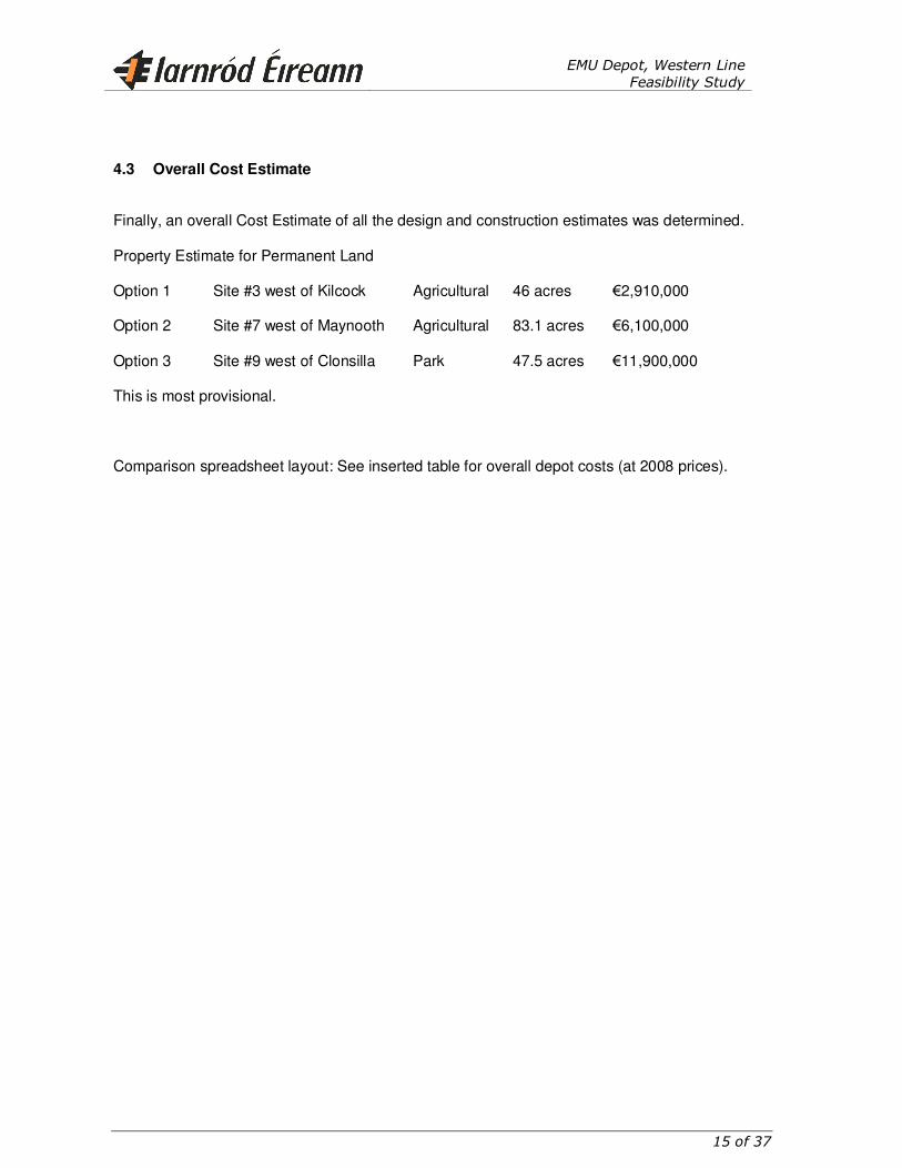
4.3 Overall Cost Estimate
Finally, an overall Cost Estimate of all the design and construction estimates was determined. Property Estimate for Permanent Land Option 1 Site #3 west of Kilcock Agricultural 46 acres €2,910,000 Option 2 Site #7 west of Maynooth Agricultural 83.1 acres €6,100,000 Option 3 Site #9 west of Clonsilla Park 47.5 acres €11,900,000 This is most provisional. Comparison spreadsheet layout: See inserted table for overall depot costs (at 2008 prices).
EMU Depot, Western Line
Feasibility Study
16 of 37
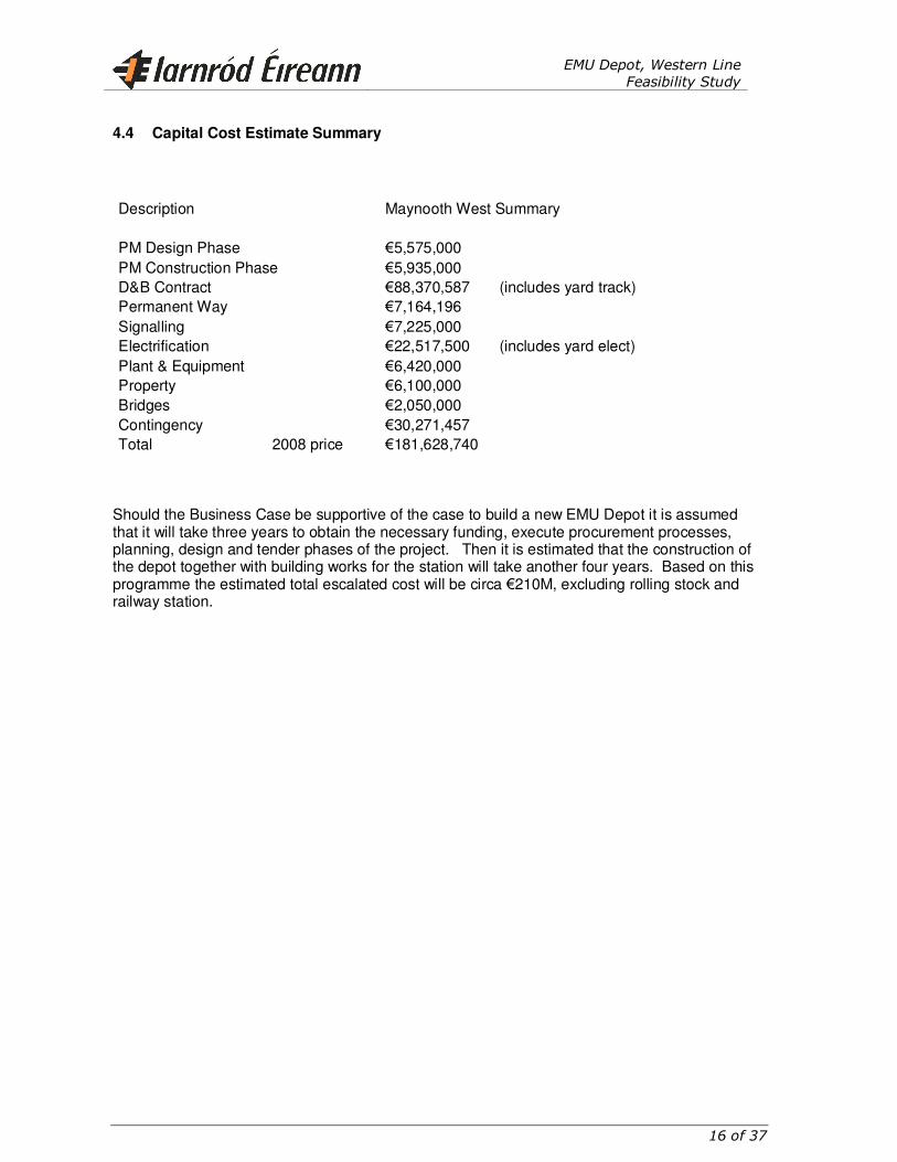
4.4 Capital Cost Estimate Summary
Description
Maynooth West Summary
PM Design Phase €5,575,000 PM Construction Phase €5,935,000 D&B Contract €88,370,587 (includes yard track) Permanent Way
€7,164,196
Signalling €7,225,000 Electrification
€22,517,500 (includes yard elect)
Plant & Equipment €6,420,000 Property €6,100,000 Bridges
€2,050,000
Contingency €30,271,457 Total
2008 price €181,628,740
Should the Business Case be supportive of the case to build a new EMU Depot it is assumed that it will take three years to obtain the necessary funding, execute procurement processes, planning, design and tender phases of the project. Then it is estimated that the construction of the depot together with building works for the station will take another four years. Based on this programme the estimated total escalated cost will be circa €210M, excluding rolling stock and railway station.
EMU Depot, Western Line
Feasibility Study
17 of 37
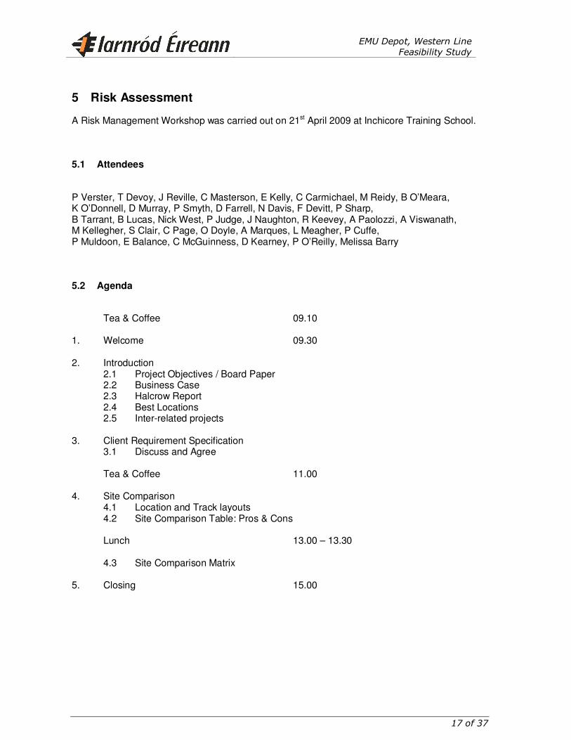
5 Risk Assessment
A Risk Management Workshop was carried out on 21st April 2009 at Inchicore Training School.
5.1 Attendees
P Verster, T Devoy, J Reville, C Masterson, E Kelly, C Carmichael, M Reidy, B O’Meara, K O’Donnell, D Murray, P Smyth, D Farrell, N Davis, F Devitt, P Sharp, B Tarrant, B Lucas, Nick West, P Judge, J Naughton, R Keevey, A Paolozzi, A Viswanath, M Kellegher, S Clair, C Page, O Doyle, A Marques, L Meagher, P Cuffe, P Muldoon, E Balance, C McGuinness, D Kearney, P O’Reilly, Melissa Barry
5.2 Agenda
Tea & Coffee 09.10 1. Welcome 09.30 2. Introduction 2.1 Project Objectives / Board Paper 2.2 Business Case 2.3 Halcrow Report 2.4 Best Locations 2.5 Inter-related projects 3. Client Requirement Specification 3.1 Discuss and Agree Tea & Coffee 11.00 4. Site Comparison 4.1 Location and Track layouts 4.2 Site Comparison Table: Pros & Cons Lunch 13.00 – 13.30 4.3 Site Comparison Matrix 5. Closing 15.00
EMU Depot, Western Line
Feasibility Study
18 of 37
After discussing the Project Objectives, the approved Board Paper, the Business Case, the Halcrow Report and the three short-listed site locations and inter-related projects, a lengthy review and discussion of the draft Client Requirement Specification document was held. It was agreed that this CRS had to be revised to incorporate the points raised.
5.3 Merits and de-merits
After discussing the three sites in detail, using the displayed maps; the various merits and de-merits of the three sites were identified and noted. See attached Table.
EMU Depot, Western Line
Feasibility Study
19 of 37
5.4 Relative Value
Then the attendees then determined the Relative Value of the three site locations using the Scoring Matrix: See attached Table.
EMU Depot, Western Line
Feasibility Study
20 of 37
5.5 Recommendation
The conclusion of the Value Management exercise was that the Maynooth West site gives the best relative value and is therefore the preferred site. Should the project business case be supportive it is recommended that the traditional process of design to Railway Order Stage and then design to tender for the design & build construction stage be followed as per the Port Laoise Depot project. After securing funding and obtaining the necessary authorisation for expenditure from the IE and CIE Boards, it is proposed to procure the professional services of a multi-discipline consultant who will design the proposed EMU Depot to Railway Order Stage and then Tender Stage.
6 Procuring and Phasing the Project
6.1 Procurement
Should the project business case be supportive it is recommended that the traditional process of design to Railway Order Stage and then design to tender for the design & build construction stage be followed. After securing funding and obtaining the necessary authorisation for expenditure from the IE and CIE Boards, it is proposed to procure the professional services of a multi-discipline consultant who will initially carry out detailed topographical and geotechnical surveys of the preferred site. The consultant will then design the civil and structural engineering aspects of the project. This design work will include track formation, drainage, ducting, new over-bridges, under-bridges and culverts (to accommodate surface water runoff), the future station and the respective parking areas, access and fencing. The track and signal designs will be carried out by IE’s New Works Department. A Quantity surveying Consultant will be also be procured and appointed to determine and monitor expenditure throughout the project. In addition to the detailed design work a Railway Order Process would also have to be applied for and obtained from the Department of Transport prior to any construction. This would include a Full Environmental Impact Assessment and consultative process with the public. Also, consultation with and the approval of the Railway Safety Commissioner would be required for certain aspects of the re-use of this railway line. The detailed design would continue during the planning process until Tenders can be sought. The Board’s authorisation would be obtained for the construction phase expenditure and the main contract awarded on receipt of the final planning decision.
EMU Depot, Western Line
Feasibility Study
21 of 37
6.2 Phasing
It is proposed that the Depot be built in phases; namely: Railway Order include whole scheme design up to tender stage Phase 1 Land Purchase of whole site Enabling Works: ESB diversions, canal over bridge & access road Site Clearance & drainage
Build 8 car long depot Build half yard track; signalling and electrification Electrify existing single mainline from Maynooth
Two mainline connections Phase 2 Complete yard trackwork Double mainline track from Maynooth incl. signalling and electrification
Add one mainline connection Diesel fuel facility Phase 3 Maynooth West Station (carpark built in phases)
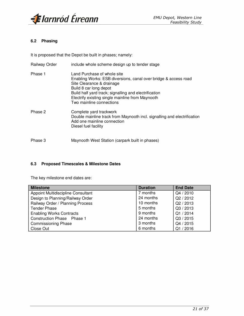
6.3 Proposed Timescales & Milestone Dates
The key milestone end dates are: Milestone Duration End Date
Appoint Multidiscipline Consultant 7 months Q4 / 2010 Design to Planning/Railway Order 24 months Q2 / 2012 Railway Order / Planning Process 10 months Q2 / 2013 Tender Phase 5 months Q3 / 2013 Enabling Works Contracts 9 months Q1 / 2014 Construction Phase Phase 1 24 months Q3 / 2015 Commissioning Phase 3 months Q4 / 2015 Close Out 6 months Q1 / 2016

EMU Depot, Western Line
Feasibility Study
22 of 37
7 APPENDICES
EMU Depot, Western Line
Feasibility Study
23 of 37
7.1 APPENDIX A
Client Requirement Specification
EMU Depot, Western Line
Feasibility Study
24 of 37
Client Requirement Specification
Contents
1. Background.
1.1 Maintenance Strategy.
2. Maintenance Requirements.
3. Facility Requirements.
3.1 Main Building.
3.2 Ancillary Workshops.
3.4 Track and Yard Facilities.
3.5 Amenity and Administration. 3.5.1 Maintenance Staff.
3.5.2 Operating Staff and Drivers.
4. Equipment Requirements. 4.1 Workshops equipment.
4.2 Office equipment.
5. Stake Holders Sign Off.
EMU Depot, Western Line
Feasibility Study
25 of 37
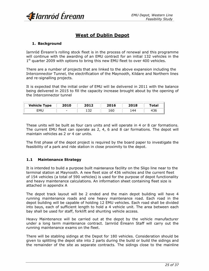
West of Dublin Depot
1. Background
Iarnród Éireann’s rolling stock fleet is in the process of renewal and this programme
will continue with the awarding of an EMU contract for an initial 132 vehicles in the 1st quarter 2009 with options to bring this new EMU fleet to over 400 vehicles.
There are a number of projects that are linked to the above expansion including the Interconnector Tunnel, the electrification of the Maynooth, Kildare and Northern lines and re-signalling projects. It is expected that the initial order of EMU will be delivered in 2011 with the balance being delivered in 2015 to fill the capacity increase brought about by the opening of the Interconnector tunnel
Vehicle Type 2010 2012 2016 2018 Total
EMU - 132 160 144 436
These units will be built as four cars units and will operate in 4 or 8 car formations. The current EMU fleet can operate as 2, 4, 6 and 8 car formations. The depot will maintain vehicles as 2 or 4 car units. The first phase of the depot project is required by the board paper to investigate the feasibility of a park and ride station in close proximity to the depot.
1.1 Maintenance Strategy
It is intended to build a purpose built maintenance facility on the Sligo line near to the terminal station at Maynooth. A new fleet size of 436 vehicles and the current fleet of 154 vehicles (a total of 590 vehicles) is used for the purpose of depot functionality and heavy maintenance calculations. An information sheet containing fleet size is attached in appendix A The depot track layout will be 2 ended and the main depot building will have 4 running maintenance roads and one heavy maintenance road. Each road in the depot building will be capable of holding 12 EMU vehicles. Each road shall be divided into bays, each of sufficient length to hold a 4 vehicle unit. The area between each bay shall be used for staff, forklift and shunting vehicle access. Heavy Maintenance will be carried out at the depot by the vehicle manufacturer under a long term maintenance contract. Iarnród Éireann Staff will carry out the running maintenance exams on the fleet. There will be stabling sidings at the Depot for 180 vehicles. Consideration should be given to splitting the depot site into 2 parts during the build or build the sidings and the remainder of the site as separate contracts. The sidings close to the mainline
EMU Depot, Western Line
Feasibility Study
26 of 37
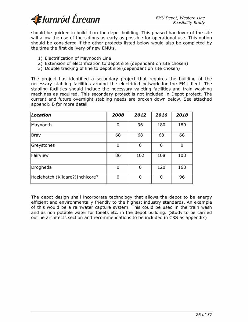
should be quicker to build than the depot building. This phased handover of the site will allow the use of the sidings as early as possible for operational use. This option should be considered if the other projects listed below would also be completed by the time the first delivery of new EMU’s.
1) Electrification of Maynooth Line 2) Extension of electrification to depot site (dependant on site chosen) 3) Double tracking of line to depot site (dependant on site chosen)
The project has identified a secondary project that requires the building of the necessary stabling facilities around the electrified network for the EMU fleet. The stabling facilities should include the necessary valeting facilities and train washing machines as required. This secondary project is not included in Depot project. The current and future overnight stabling needs are broken down below. See attached appendix B for more detail Location 2008 2012 2016 2018
Maynooth 0 96 180 180
Bray 68 68 68 68
Greystones 0 0 0 0
Fairview 86 102 108 108
Drogheda 0 0 120 168
Hazlehatch (Kildare?)Inchicore? 0 0 0 96
The depot design shall incorporate technology that allows the depot to be energy efficient and environmentally friendly to the highest industry standards. An example of this would be a rainwater capture system. This could be used in the train wash and as non potable water for toilets etc. in the depot building. (Study to be carried out be architects section and recommendations to be included in CRS as appendix)
EMU Depot, Western Line
Feasibility Study
27 of 37
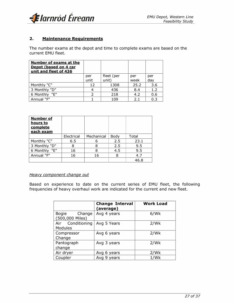
2. Maintenance Requirements The number exams at the depot and time to complete exams are based on the current EMU fleet. Number of exams at the
Depot (based on 4 car unit and fleet of 436
per unit
fleet (per unit)
per week
per day
Monthly "C" 12 1308 25.2 3.6 3 Monthly "D" 4 436 8.4 1.2 6 Monthly "E" 2 218 4.2 0.6 Annual "F" 1 109 2.1 0.3 Number of hours to
complete each exam Electrical Mechanical Body Total Monthly "C" 6.5 6 2.5 23.1 3 Monthly "D" 8 8 2.5 9.5 6 Monthly "E" 16 8 4.5 9.5 Annual "F" 16 16 8 4.7 46.8 Heavy component change out Based on experience to date on the current series of EMU fleet, the following frequencies of heavy overhaul work are indicated for the current and new fleet.
Change Interval
(average) Work Load
Bogie Change (500,000 Miles)
Avg 4 years 6/Wk
Air Conditioning Modules
Avg 5 Years 2/Wk
Compressor Change
Avg 6 years 2/Wk
Pantograph change
Avg 3 years 2/Wk
Air dryer Avg 6 years 2/Wk Coupler Avg 9 years 1/Wk
EMU Depot, Western Line
Feasibility Study
28 of 37
3. Facility Requirements
Based on the above discussion, the following facilities are required to maintain the EMU Fleet.
� Main Depot Building � Ancillary Workshops � Stores � Track and Yard Facilities � Amenity and Administration Facilities � Equipment Requirements � Operating Department/Drivers Facilities
The final design of the building shall incorporate lean manufacturing techniques as they apply to the rail maintenance business. 3.1 Main Building A Depot Maintenance Building will be approx 270 metres long by 55m. This length will be sufficient to accommodate a twelve car EMU. The Depot to have 6 Mts. access aprons at each end inside the building. Outside the building there shall be a 10m access apron. This depot shall have four Running Maintenance roads on pedestal track with a Heavy Maintenance road equipped with lifting equipment for bogie and heavy underframe component changes. The “Heavy” road will be on flat floor. Control of the OHLE in the depot building shall be as automated as possible. Proposals for this to be approved by IÉ during design process. It should be noted that the 8500, 8510, 8520 and new EMU fleet (to be purchased) are all configured in 4 vehicle units. The 8100 and 8200 are configured in 2 vehicle units There will be three separate lifting systems on the Heavy Maintenance road:
(A) For the use of the Iarnród Eireann staff: two in-floor jacking systems will be provided. Each shall be capable of simultaneously lifting a four vehicle EMU unit without uncoupling. (or 2 a by 2 vehicle unit)
(B) There shall be a separate in-floor jacking system to be provided sufficient to simultaneously lift a four EMU vehicle unit (or a 2 by 2 vehicle unit). This is for the use of the Heavy Maintenance contractor.
Heavy Lift Road Description: There will be 3 heavy maintenance bays on the Heavy Maintenance road. Each bay shall have a lifting system and roof access gantry that will cater for units of up to 4 vehicle length.
EMU Depot, Western Line
Feasibility Study
29 of 37
Each Unit will move into place under its own power using the OHLE equipment. The overhead line equipment shall be capable of removing the wire/bar either horizontally or vertically to allow sufficient space to lift each unit with the in-floor lifting system. Which ever configuration is used to move the OHLE to allow the unit to be lifted, it shall not inhibit the use of the 10 tonne overhead cranes. The in-floor lifting system will cater for all existing EMU configurations and the new EMU fleet (the commuter DMU fleet shall also be capable of being lifted by default on this system due to the similar bogie centre and lifting pad spacing). A permanent 4 vehicle long roof access gantry shall be built on the HM road at each HM bay. The gantry will be on the non-office side of the HM road beside the LM roads. Each roof access system shall have appropriate safety interlocking to prevent staff gaining access to the access steps unless the OHLE is switched off. The interlocking system will not allow the OHLE to be switch back on until staff left the roof area. Wheelset removal: The area between the tracks on the HM road will contain a pit to allow wheelsets to be rolled out from underneath each 2 or 4 vehicle unit. The pitted area is required to allow staff to work underneath and also allow the traction motor to hang down from the axle under gravity. The length of the traction motor is greater than the diameter of the wheelset. The pitted area will be interrupted between HM bays to allow forklift access across all maintenance roads and to allow a shunting vehicle remove itself from any road. Weighing equipment: At each end of the Heavy Maintenance road a set of train weighing equipment will be provided. This equipment will give an output of the load from each wheel on a unit. This equipment will require a pitted area of approximately 1m depth and will require a section of track carried by pedestals. The deflection of the rail between the pedestals allows the load of each wheel to be calculated by the weighing equipment. The weighing equipment shall be left in place and the pitted area will be normally covered. The pit cover be capable of bearing the load of a forklift and shall be easily removed. The heavy maintenance road shall be straddled by two 10 Tonne Cranes to remove roof mounted air conditioning units and other equipment. All of the five roads in the Depot will require sufficient clearance on each side to accommodate a forklift. Each road to be equipped with dispensing points for Transmission Oils and waste oil removal equipment. The Running Maintenance Roads shall also have roof access gantries (at 25% of vehicle positions) and over head crane facilities with suitable safety interlocking to prevent staff gaining access and working unless the overhead line is dead.
In order to facilitate the removal of underframe equipment, sufficient clearance must be provided to enable a forklift truck to access. The minimum clearance between
EMU Depot, Western Line
Feasibility Study
30 of 37
centre lines of tracks is shown in the attached depot building layout. This will imply an overall width of the building of approx 55m. Suitable Scissors type Lift of 6 Tonnes capacity to be provided on the Heavy Maintenance Road to remove underframe mounted equipment such as compressors. An underframe washing facility to be provided positioned on the entry to the Heavy Maintenance Road of the Depot. This shall be of sufficient depth to allow staff to safely stand erect under a vehicle while cleaning. All of the roads in the Depot must have a suitable protection system to safeguard workers. A Depot Protection System that provides this in conjunction with a Depot Management system is required. This system to be operated from the Depot Controllers office. An audible and visible system to be provided to warn workers of all train movements in the Depot. This system shall also be placed on the roads leading to the underfloor lathe building A fire alarm system is required. This to be actuated by combined heat/optical detectors. The fire panel to be situated in the administration block. A fire suppression system to be provided suitable for extinguishing oil fires. A Public Address system to be installed. Speakers to be installed in all occupied areas. The system to be operated from the foreman’s office. A CCTV security system to be provided with the monitor for the system to be installed in the security office. All areas of the depot and buildings to be monitored. The facility to be equipped with its own PABX system with a telephone outlet at each desk in the administration block, foreman’s offices, stores and ancillary workshops. A dedicated Server to be provided in the facility. Two data outlets to be provided at each desk in the administration block, foreman’s offices, stores and ancillary workshops. 3.2 Ancillary Workshops An ancillary workshop area is required, of approx. 600 M2, this to be divided into various areas appropriate to the various activities in the Depot to facilitate light repairs to small components and provide storage for personnel tools of maintenance personnel. A small training facility is also required which can double as specialised equipment test/repair area. These to be allocated as follows: - Mechanical Workshop 10 X 6 (60 m2) Bodywork Workshop 10 X 6 (60 m2)
EMU Depot, Western Line
Feasibility Study
31 of 37
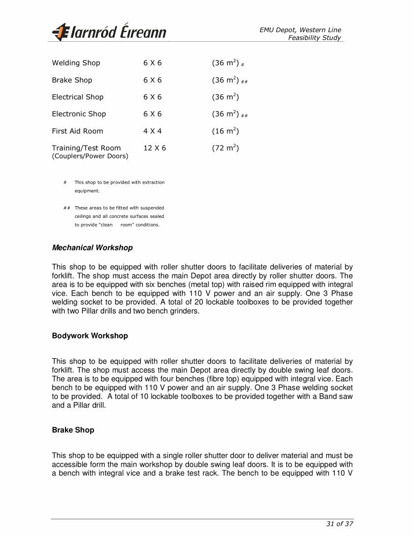
Welding Shop 6 X 6 (36 m2) # Brake Shop 6 X 6 (36 m2) ## Electrical Shop 6 X 6 (36 m2) Electronic Shop 6 X 6 (36 m2) ##
First Aid Room 4 X 4 (16 m2) Training/Test Room 12 X 6 (72 m2) (Couplers/Power Doors)
# This shop to be provided with extraction
equipment.
## These areas to be fitted with suspended
ceilings and all concrete surfaces sealed
to provide “clean room” conditions.
Mechanical Workshop
This shop to be equipped with roller shutter doors to facilitate deliveries of material by forklift. The shop must access the main Depot area directly by roller shutter doors. The area is to be equipped with six benches (metal top) with raised rim equipped with integral vice. Each bench to be equipped with 110 V power and an air supply. One 3 Phase welding socket to be provided. A total of 20 lockable toolboxes to be provided together with two Pillar drills and two bench grinders.
Bodywork Workshop
This shop to be equipped with roller shutter doors to facilitate deliveries of material by forklift. The shop must access the main Depot area directly by double swing leaf doors. The area is to be equipped with four benches (fibre top) equipped with integral vice. Each bench to be equipped with 110 V power and an air supply. One 3 Phase welding socket to be provided. A total of 10 lockable toolboxes to be provided together with a Band saw and a Pillar drill.
Brake Shop
This shop to be equipped with a single roller shutter door to deliver material and must be accessible form the main workshop by double swing leaf doors. It is to be equipped with a bench with integral vice and a brake test rack. The bench to be equipped with 110 V
EMU Depot, Western Line
Feasibility Study
32 of 37
power and an air supply. One 3 Phase welding socket to be provided. The shop must be equipped with a suspended ceiling and all concrete surfaces must be sealed.
Two lockable toolboxes to be provided.
Electrical Shop
This shop to be equipped with a single roller shutter door to deliver material and must be accessible form the main workshop by double swing leaf doors. It is to be equipped with two benches (Fibre top) with integral vices. Each bench to be equipped with 110 V power and an air supply. One 3 Phase welding socket to be provided. The shop must be equipped with a suspended ceiling and all concrete surfaces must be sealed.
Four lockable toolboxes to be provided.
Electronic Shop
This shop to be equipped with a single roller shutter door to deliver material and must be accessible form the main workshop by double swing leaf doors. It is to be equipped with a bench (Fibre top) with integral vice. The bench to be equipped with 110 V power and an air supply. The shop must be equipped with a suspended ceiling and all concrete surfaces must be sealed. Two lockable toolboxes to be provided.
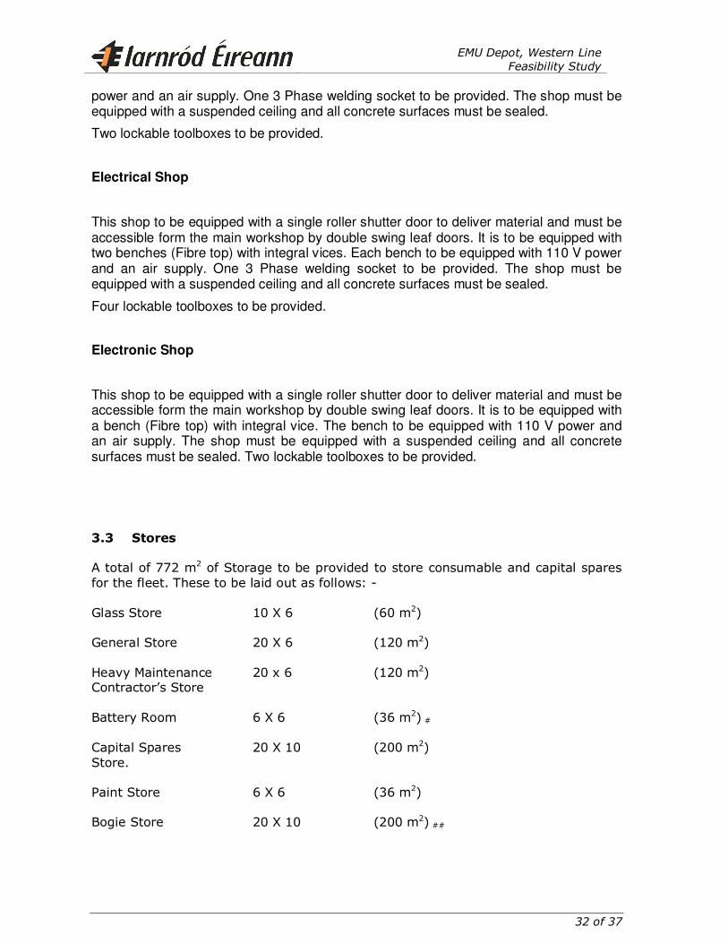
3.3 Stores
A total of 772 m2 of Storage to be provided to store consumable and capital spares for the fleet. These to be laid out as follows: - Glass Store 10 X 6 (60 m2) General Store 20 X 6 (120 m2) Heavy Maintenance 20 x 6 (120 m2) Contractor’s Store Battery Room 6 X 6 (36 m2) # Capital Spares 20 X 10 (200 m2) Store. Paint Store 6 X 6 (36 m2) Bogie Store 20 X 10 (200 m2) ##
EMU Depot, Western Line
Feasibility Study
33 of 37
# This area to be equipped with extraction and flameproof switches and fittings.
## This area need not be accommodated in a building, a light roof would suffice. It must be adjacent to the heavy
lift road.
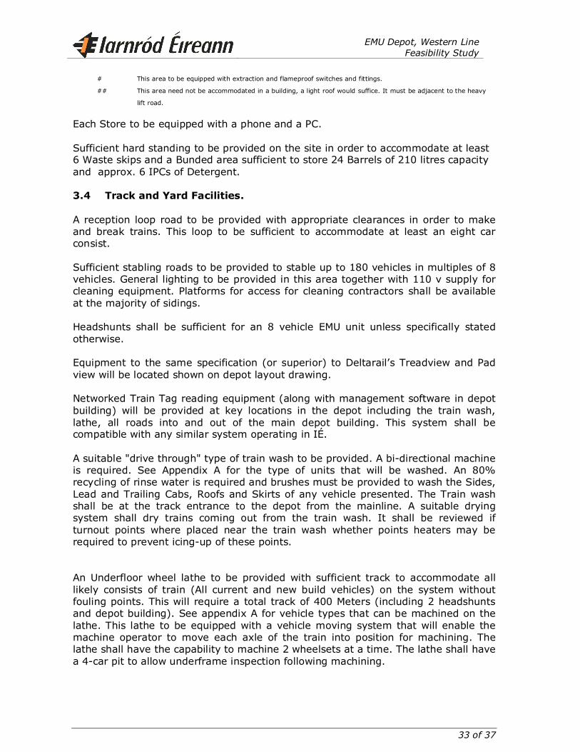
Each Store to be equipped with a phone and a PC. Sufficient hard standing to be provided on the site in order to accommodate at least 6 Waste skips and a Bunded area sufficient to store 24 Barrels of 210 litres capacity and approx. 6 IPCs of Detergent. 3.4 Track and Yard Facilities.
A reception loop road to be provided with appropriate clearances in order to make and break trains. This loop to be sufficient to accommodate at least an eight car consist. Sufficient stabling roads to be provided to stable up to 180 vehicles in multiples of 8 vehicles. General lighting to be provided in this area together with 110 v supply for cleaning equipment. Platforms for access for cleaning contractors shall be available at the majority of sidings. Headshunts shall be sufficient for an 8 vehicle EMU unit unless specifically stated otherwise. Equipment to the same specification (or superior) to Deltarail’s Treadview and Pad view will be located shown on depot layout drawing. Networked Train Tag reading equipment (along with management software in depot building) will be provided at key locations in the depot including the train wash, lathe, all roads into and out of the main depot building. This system shall be compatible with any similar system operating in IÉ. A suitable "drive through" type of train wash to be provided. A bi-directional machine is required. See Appendix A for the type of units that will be washed. An 80% recycling of rinse water is required and brushes must be provided to wash the Sides, Lead and Trailing Cabs, Roofs and Skirts of any vehicle presented. The Train wash shall be at the track entrance to the depot from the mainline. A suitable drying system shall dry trains coming out from the train wash. It shall be reviewed if turnout points where placed near the train wash whether points heaters may be required to prevent icing-up of these points. An Underfloor wheel lathe to be provided with sufficient track to accommodate all likely consists of train (All current and new build vehicles) on the system without fouling points. This will require a total track of 400 Meters (including 2 headshunts and depot building). See appendix A for vehicle types that can be machined on the lathe. This lathe to be equipped with a vehicle moving system that will enable the machine operator to move each axle of the train into position for machining. The lathe shall have the capability to machine 2 wheelsets at a time. The lathe shall have a 4-car pit to allow underframe inspection following machining.
EMU Depot, Western Line
Feasibility Study
34 of 37
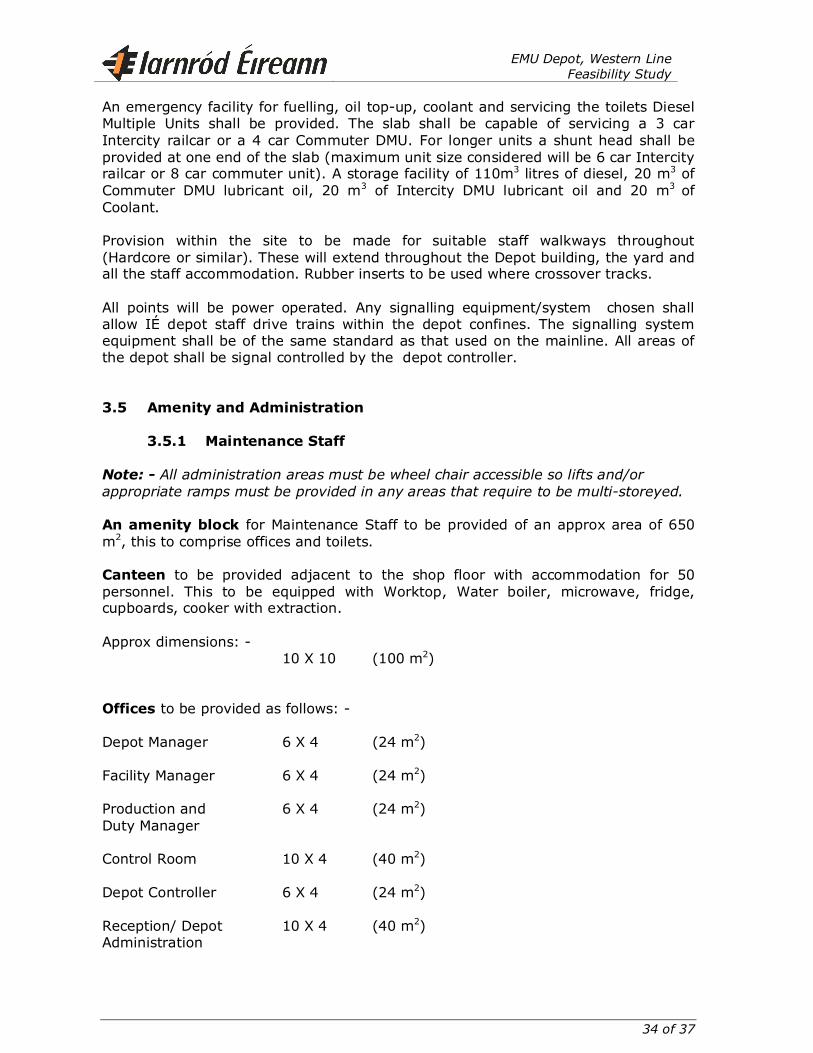
An emergency facility for fuelling, oil top-up, coolant and servicing the toilets Diesel Multiple Units shall be provided. The slab shall be capable of servicing a 3 car Intercity railcar or a 4 car Commuter DMU. For longer units a shunt head shall be provided at one end of the slab (maximum unit size considered will be 6 car Intercity railcar or 8 car commuter unit). A storage facility of 110m3 litres of diesel, 20 m3 of Commuter DMU lubricant oil, 20 m3 of Intercity DMU lubricant oil and 20 m3 of Coolant. Provision within the site to be made for suitable staff walkways throughout (Hardcore or similar). These will extend throughout the Depot building, the yard and all the staff accommodation. Rubber inserts to be used where crossover tracks. All points will be power operated. Any signalling equipment/system chosen shall allow IÉ depot staff drive trains within the depot confines. The signalling system equipment shall be of the same standard as that used on the mainline. All areas of the depot shall be signal controlled by the depot controller. 3.5 Amenity and Administration
3.5.1 Maintenance Staff
Note: - All administration areas must be wheel chair accessible so lifts and/or
appropriate ramps must be provided in any areas that require to be multi-storeyed.
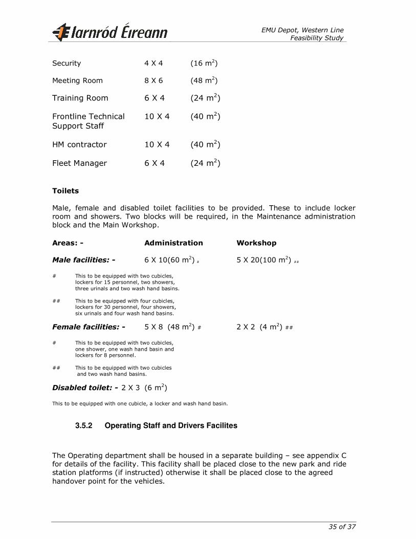
An amenity block for Maintenance Staff to be provided of an approx area of 650 m2, this to comprise offices and toilets. Canteen to be provided adjacent to the shop floor with accommodation for 50 personnel. This to be equipped with Worktop, Water boiler, microwave, fridge, cupboards, cooker with extraction. Approx dimensions: - 10 X 10 (100 m2) Offices to be provided as follows: - Depot Manager 6 X 4 (24 m2) Facility Manager 6 X 4 (24 m2) Production and 6 X 4 (24 m2) Duty Manager Control Room 10 X 4 (40 m2) Depot Controller 6 X 4 (24 m2) Reception/ Depot 10 X 4 (40 m2) Administration
EMU Depot, Western Line
Feasibility Study
35 of 37
Security 4 X 4 (16 m2) Meeting Room 8 X 6 (48 m2)
Training Room 6 X 4 (24 m2) Frontline Technical 10 X 4 (40 m2) Support Staff HM contractor 10 X 4 (40 m2) Fleet Manager 6 X 4 (24 m2) Toilets Male, female and disabled toilet facilities to be provided. These to include locker room and showers. Two blocks will be required, in the Maintenance administration block and the Main Workshop. Areas: - Administration Workshop
Male facilities: - 6 X 10(60 m2) # 5 X 20(100 m2) ## # This to be equipped with two cubicles, lockers for 15 personnel, two showers, three urinals and two wash hand basins.
## This to be equipped with four cubicles, lockers for 30 personnel, four showers, six urinals and four wash hand basins.
Female facilities: - 5 X 8 (48 m2) # 2 X 2 (4 m2) ## # This to be equipped with two cubicles, one shower, one wash hand basin and lockers for 8 personnel. ## This to be equipped with two cubicles and two wash hand basins.
Disabled toilet: - 2 X 3 (6 m2)
This to be equipped with one cubicle, a locker and wash hand basin.
3.5.2 Operating Staff and Drivers Facilites
The Operating department shall be housed in a separate building – see appendix C for details of the facility. This facility shall be placed close to the new park and ride station platforms (if instructed) otherwise it shall be placed close to the agreed handover point for the vehicles.
EMU Depot, Western Line
Feasibility Study
36 of 37
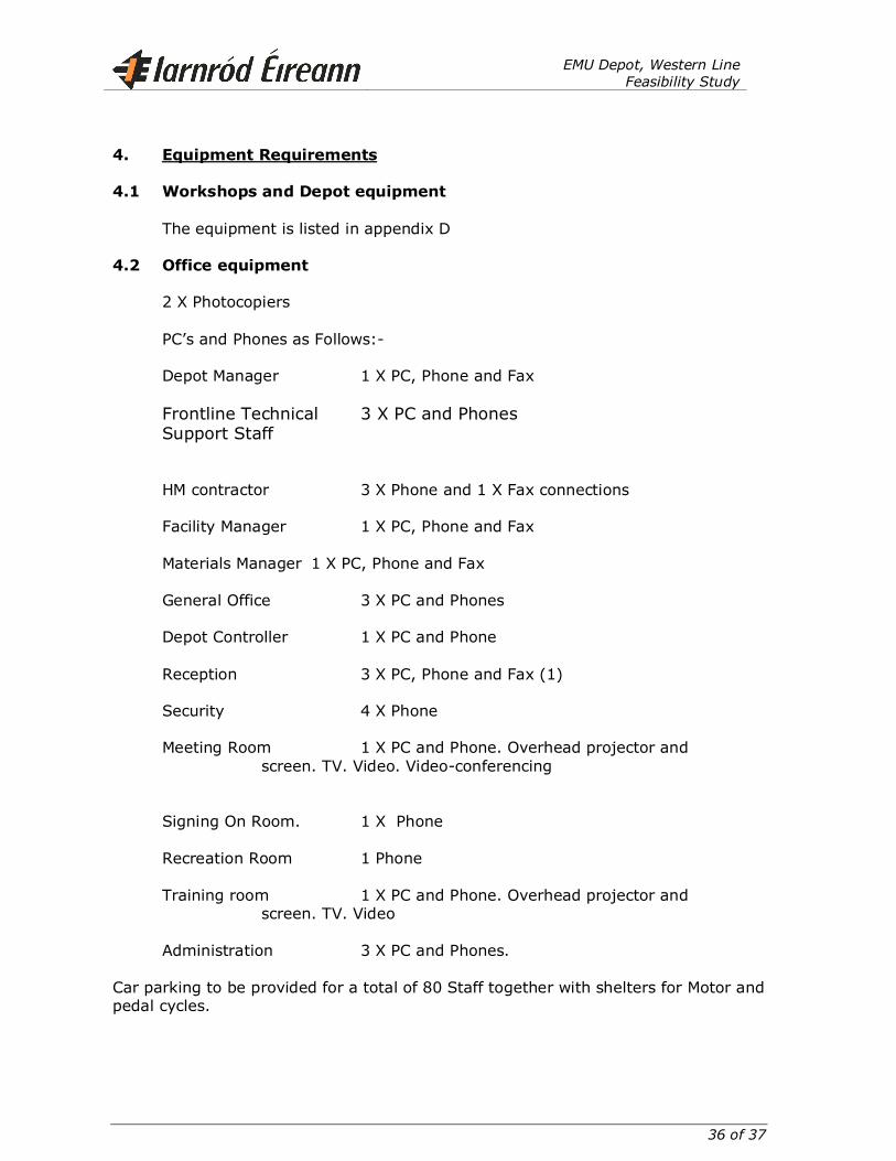
4. Equipment Requirements
4.1 Workshops and Depot equipment
The equipment is listed in appendix D 4.2 Office equipment
2 X Photocopiers PC’s and Phones as Follows:- Depot Manager 1 X PC, Phone and Fax Frontline Technical 3 X PC and Phones
Support Staff HM contractor 3 X Phone and 1 X Fax connections
Facility Manager 1 X PC, Phone and Fax Materials Manager 1 X PC, Phone and Fax General Office 3 X PC and Phones Depot Controller 1 X PC and Phone Reception 3 X PC, Phone and Fax (1) Security 4 X Phone Meeting Room 1 X PC and Phone. Overhead projector and screen. TV. Video. Video-conferencing
Signing On Room. 1 X Phone Recreation Room 1 Phone Training room 1 X PC and Phone. Overhead projector and screen. TV. Video
Administration 3 X PC and Phones. Car parking to be provided for a total of 80 Staff together with shelters for Motor and pedal cycles.
EMU Depot, Western Line
Feasibility Study
37 of 37
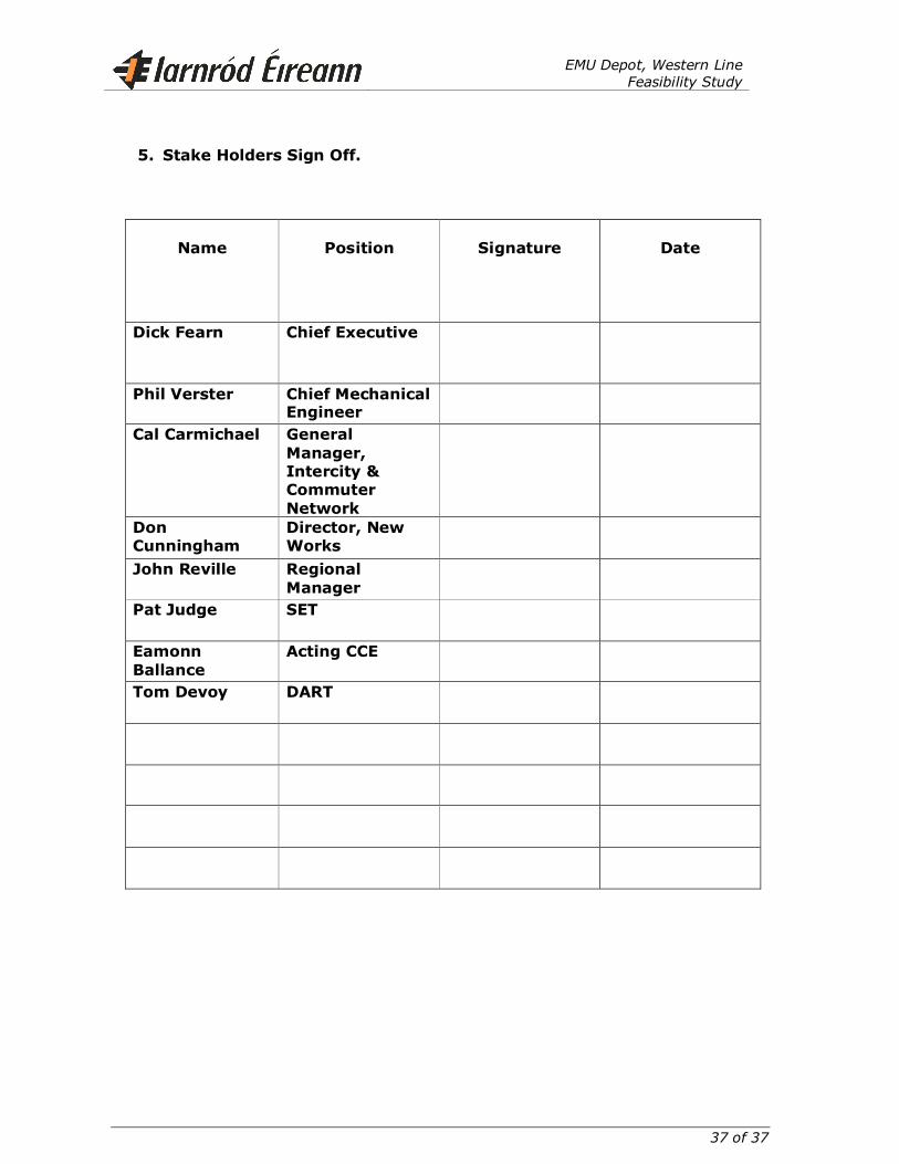
5. Stake Holders Sign Off.
Name
Position
Signature
Date
Dick Fearn Chief Executive
Phil Verster Chief Mechanical Engineer
Cal Carmichael General
Manager, Intercity & Commuter
Network
Don Cunningham
Director, New Works
John Reville Regional
Manager
Pat Judge SET
Eamonn
Ballance
Acting CCE
Tom Devoy DART