Embed Size (px)
Citation preview

EMTP Modellin g of Control andPower Electronic Devices for
Electric Power Quality AssessmentPh.D. Thesis
by
Benedito Donizeti Bonatto
Supervisor: Dr. Hermann W. Dommel
Co-Supervisor: Dr. William G. Dunford
[email protected] 2, 2001,Vancouver, B.C., Canada.
The University of British ColumbiaDepartment of Electrical and Computer Engineering
2356 Main Mall, V6T1Z4, Vancouver, B.C. Canada
Objectives of the project
To develop reasonably accurate models forcontrol and power electronic devices to evaluatetheir impact on the quality of power.
Models were developed for implementation in theElectromagnetic Transients Program (EMTP ), orin similar programs.

Outline of the presentation
Electric Power Quality and Power Electronics
Simultaneous Solution of Control and ElectricPower System Equations (SSCPS)
Power Electronics Modelling in EMTP-basedSimulations
Evaluation of the Impact of Power ElectronicDevices on the Quality of Power
Conclusions

Electric Power Quality and PowerElectronics: an Overview
Why is Power Quality Important?
– High costs ( $ ) related to the “poor” power quality.
– Electricity customers demand better quality on thepower.
– Increasing use of power electronic devices.– Increasing use of sensitive load equipment.
– Deregulation in the electricity industry , thus stimulatingcompetition.
– IEEE Standards

EMTP-type Simulation of Control Systems
Previous developments– TACS - Transient Analysis of Control Systems,
1977 (1 ∆t delay problem):
– MODELS, 1993.
– A. E. Araújo approach, 1993.
Elect r ic Network Solut ion( EMTP )
Cont ro l Sys tem Solut ion( TACS )
T ime De lay1 ∆t
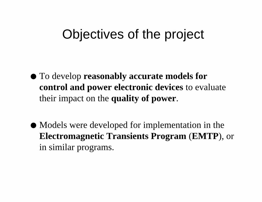
the effect of a one time step (1 ∆t) delay inthe solution of EMTP-based simulation
0 10 20 30 40 50 60 70 80−8
−6
−4
−2
0
2
4
6
8
Time ( s )
Vo
ltag
e (
V )
vout
vin
Solution of a second order linear systemwith poles on the imaginary axis of the complex plane
1_ _ _ _ _
s-
+
1_ _ _ _ _
s
>9@
Y,1
Y287

the effect of a one time step (1 ∆t) delay inthe solution of EMTP-based simulation
0 10 20 30 40 50 60 70 80−8
−6
−4
−2
0
2
4
6
8
Time ( s )
Vo
ltag
e (
V )
vout
vin
Solution of a second order linear system with unstable oscillations caused by theintroduction of one time step delay
1_____
s-+
1_____
s
>9@
Y,1
Y287
delay1 ∆t
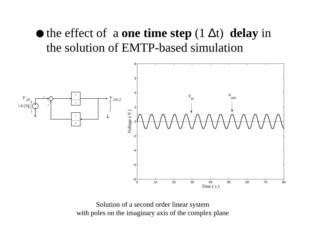
Simultaneous Solution of Control andElectric Power System Equations (SSCPS)
“Circuit approach” with the compensationmethod and Newton-Raphson iterativealgorithm for:– Current and Voltage Dependent Sources
– Transfer functions
– Limiters (hard and soft ; dynamic and static)
– Control Devices
Main advantage: “generality and flexibility”
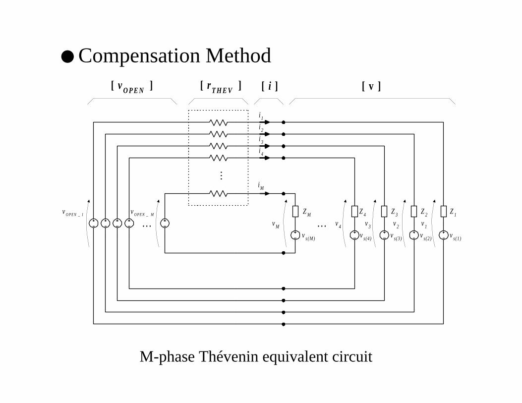
Compensation Method
M-phase Thévenin equivalent circuit
vM
vs(M)
ZM
[ r T H E V ][ vO P E N ] [ i ]
vs(4)
Z4
vs(3)
Z3
vs(2)
Z2
vs(1)
Z1
[ v ]
... ...
...
v4 v3 v2 v1
i 1
i 2
i 3
i 4
i M
vO P E N _ MvO P E N _ 1
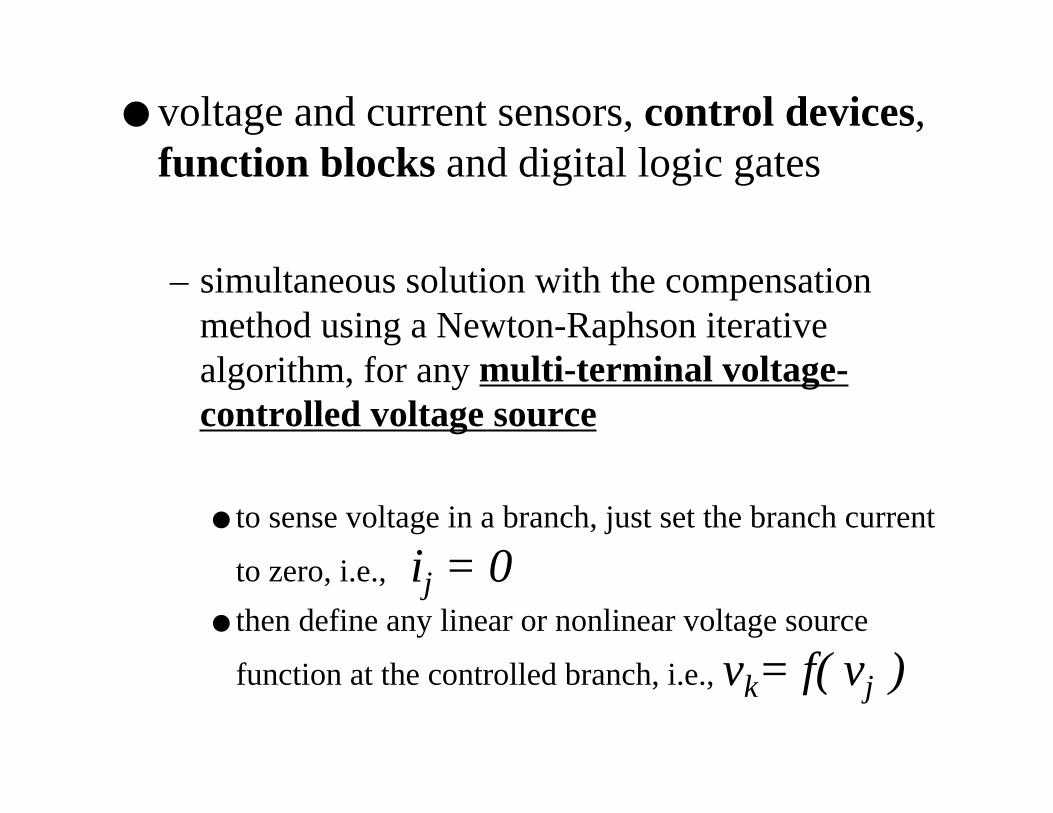
voltage and current sensors, control devices,function blocks and digital logic gates
– simultaneous solution with the compensationmethod using a Newton-Raphson iterativealgorithm, for any multi-terminal voltage-controlled voltage source
to sense voltage in a branch, just set the branch current
to zero, i.e., ij = 0 then define any linear or nonlinear voltage source
function at the controlled branch, i.e., vk= f( vj )

Newton-Raphson
Algorithm with
solution for limits
INPUT DATA
INIT IAL GUESSF O R C U R R E N T S
C A L C U L A T I O N O FB R A N C H V O L T A G E S[from Eq. (2.6) or (2.1)]
C A L C U L A T I O N O FRIGHT HAND S IDE
[negat ive valuesof Eq. (2.1)]
IS ITACCURATEENOUGH?
BUILD JACOBIAN MATRIX[part ial derivatives
of Eq. (2.1)]
S O L V E F O R C U R R E N T S
C H E C K F O R LIMITS
R E T U R N C U R R E N T S TO MAIN PROGRAM
IS THEREANY LIMIT
VIOLATION?Yes
Yes
U P D A T EC U R R E N T S
N o
SET VARIABLETO ITS LIMIT
MAX. NO. OFITERATIONS WAS
EXCEEDED?
N o
N o
Yes S T O P

Practical Applications
– Dependent Sources: Current-Controlled Voltage Source (CCVS)
Current-Controlled Current Source (CCCS)
Voltage-Controlled Voltage Source (VCVS)
Voltage-Controlled Current Source (VCCS)
– Independent Sources (connected between twoungrounded nodes)
– “Ideal” Operational amplifiers(ij=0 and vj=0)
– Ideal Transformers;
– Current and voltage sensors;

Transfer function implementation1 1
1 1 01 1
1 1 0
...( ) ( )( )
( ) ... ( )
0
m mm m
n nn n
n
b s b s b s bX s B sH s k k
U s a s a s a s a A s
n m a
−−
−−
+ + + += = = + + + +
≥ ≠
kb1_ _ _an
a1_ _ _an
1_ _ _
s
+
-
kb0_ _ _an
a0_ _ _an
1_ _ _
s
+
-
kbn_ _ _an
+
kbn-1_ _ _an
an-1_ _ _an
1_ _ _
s
+
-
+++
U ( s )
X ( s )
. . .
. . .
. . .
X ( s )U ( s )H ( s )

Transfer function implementation1 1
1 1 01 1
1 1 0
...( ) ( )( )
( ) ... ( )
0
m mm m
n nn n
n
b s b s b s bX s B sH s k k
U s a s a s a s a A s
n m a
−−
−−
+ + + += = = + + + +
≥ ≠
u ( t )
x ( t )
. . .
. . .
. . .
an___ M Ωkb0
an___ M Ωkb1
an_ _ _ M Ωkbn-1
an_ _ _ M Ωkbn
an_ ___ M Ω a0
an_ ___ M Ω a1
an_ ___ M Ω an -1
1 M Ω1 M Ω
1 M Ω1 M Ω
-1µ F-1µ F
-1µ F- 1 M Ω
X ( s )U ( s )H ( s )

Example: First Order Transfer Function
X ( s )U ( s )1 0
_ _ _ _ _ _ _ _ _ _
0.01 s + 1
kb0_ _ _a1
a0_ _ _a1
1_ _ _
s
+
-
U ( s )
X ( s )
u ( t )
x ( t )
a1___ M Ωkb0
a1_ ___ M Ω a0
- 1µ Fu ( t ) x ( t )1 k Ω
- 10 k Ω
- 1µ F
=

basic control blocks, transfer functions andfilters
Classical linearized “swing equation” used in power system small signal stability studies of a single machine connected to an infinite bus
K S
K D
ω0_____
s
1_____2H s
-
-
+ ∆δ∆ωU
∆Tes
∆Ted
∆7D∆T m
SX
. ωn2
_ _ _ _ _ _ _ _ _ _ _ _ _ _ _ _ _s2 + 2 ξωn s + ωn
2
∆δ∆7P
SX

basic control blocks, transfer functions andfilters
Simulation results of the synchronous machine rotor angle deviation,in the presence of a positive damping torque coefficient
0 1 2 3 4 5 6 7 8 9 10−0.25
−0.2
−0.15
−0.1
−0.05
0
0.05
0.1
Time ( s )
Va
ria
ble
s in
pe
r u
nit
( p
.u. )
∆
5*
Tes
Ted
Ta
∆ω
Tm
∆δ
∆
∆
∆
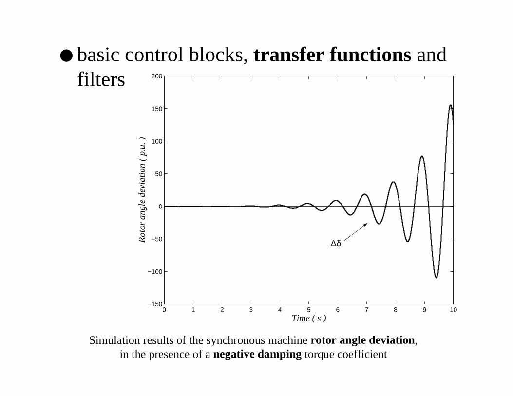
basic control blocks, transfer functions andfilters
Simulation results of the synchronous machine rotor angle deviation,in the presence of a negative damping torque coefficient
0 1 2 3 4 5 6 7 8 9 10−150
−100
−50
0
50
100
150
200
Time ( s )
Ro
tor
an
gle
de
via
tion
( p
.u. )
∆δ

Power Electronics Modelling in EMTP-based Simulations
Development of subroutine GATE– allows in MicroTran the dynamic firing control
of simplified models for thyristors, GTO’sIGBT’s, represented as EMTP-based voltage-controlled switches
Development of a “simultaneous” solutionfor voltage-controlled switches
Implementation of nonlinear diode model inEMTP-based programs

Evaluation of the Impact of PowerElectronic Devices on the Quality of Power
Dynamic interaction between powerelectronic devices and power systems
Power quality assessment through EMTP-based programs
EMTP-based simulation cases with SSCPS -Simultaneous Solution of Control and ElectricPower System Equations
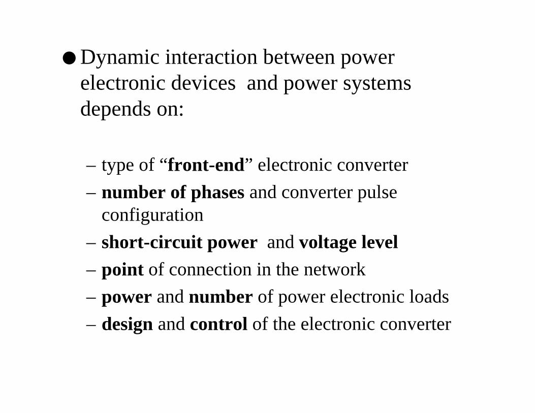
Dynamic interaction between powerelectronic devices and power systemsdepends on:
– type of “front-end” electronic converter
– number of phases and converter pulseconfiguration
– short-circuit power and voltage level– point of connection in the network
– power and number of power electronic loads
– design and control of the electronic converter
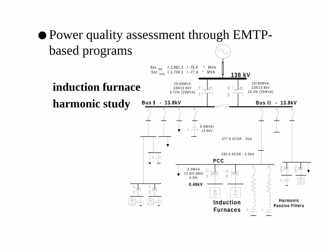
Power quality assessment through EMTP-based programs
induction furnace
harmonic study
138 kV
Bus , - 13.8kV Bus I I - 13.8kV
InductionFurnaces
HarmonicPassive Filters
PCC
477.0 ACSR - 2km
25 /30MVA138/13.8kV
9.72% (25MVA)
25 /30MVA138/13.8kV
10.2% (25MVA)
Ssc 3ph = 2,881.3 / -78.0 o MVASsc 1phg = 1,734.1 / -77.4 o MVA
9.0MVAr13.8kV
3 .0MVA13.8/0.48kV
5.9%
336.4 ACSR - 0 .5km
0.48kV
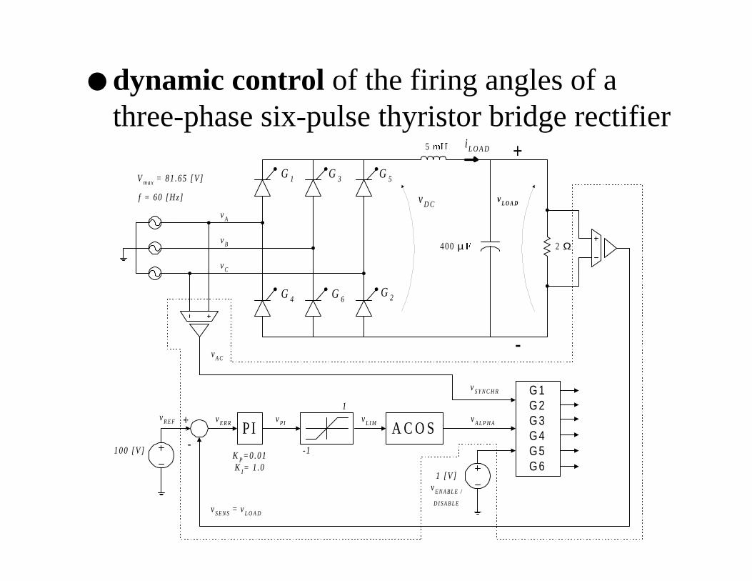
dynamic control of the firing angles of athree-phase six-pulse thyristor bridge rectifier
G 1
2 Ω
i L O A D
Vm a x = 81.65 [V]
f = 60 [Hz] vL O A D
vS Y N C H R
vA
400 µ )
vD C
5 P+ +
-
vB
vC
PI A C O S
G 1G 2G 3G 4G 5G 6
G 3 G 5
G 4 G 6G 2
vA L P H A
vE N A B L E /
D I S A B L E
vL I MvPIvE R RvR E F
vS E N S = vL O A D
-
+
100 [V ]
1 [V ]
K P=0.01K I= 1.0
1
-1
vA C

dynamic control of the firing angles of athree-phase six-pulse thyristor bridge rectifier
0 5 10 15 20 25−150
−100
−50
0
50
100
150
Time ( ms )
Vo
ltag
e (
V )
C
urr
en
t (
A )
iLOAD
vsynchr
vLOAD
vDC
vA
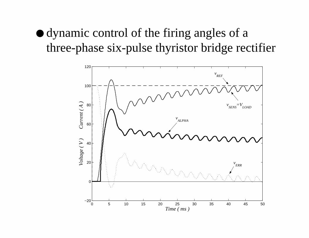
dynamic control of the firing angles of athree-phase six-pulse thyristor bridge rectifier
0 5 10 15 20 25 30 35 40 45 50−20
0
20
40
60
80
100
120
Time ( ms )
Vo
ltag
e (
V )
C
urr
en
t (
A )
vALPHA
vREF
vERR
vSENS
=VLOAD
dynamic control of the firing angles of athree-phase six-pulse thyristor bridge rectifier
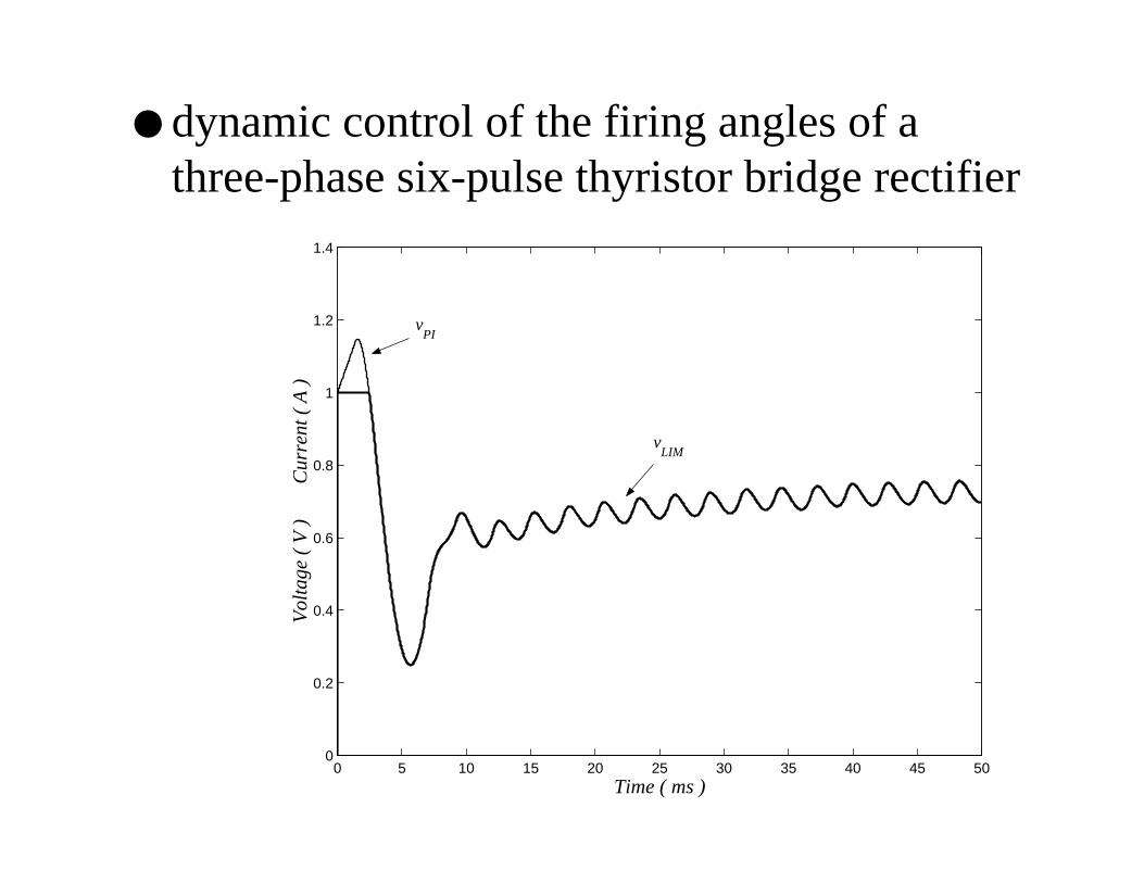
0 5 10 15 20 25 30 35 40 45 500
0.2
0.4
0.6
0.8
1
1.2
1.4
Time ( ms )
Vo
ltag
e (
V )
C
urr
en
t (
A )
vLIM
vPI
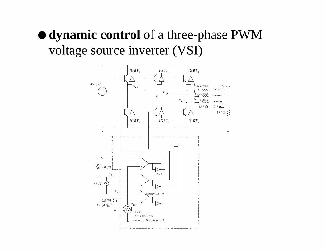
dynamic control of a three-phase PWMvoltage source inverter (VSI)
I G B T1 I G B T3 I G B T5
I G B T4 I G B T6 I G B T2
vTRI
vA
vB
vC
vS A
vS B
vS C
vNEUTRi S A - N E U T R
i S B - N E U T R
i S C - N E U T R
0.8 [V]
0.8 [V]
0.8 [V]
1 [V]
10 9 Ω
3.87 Ω 7.7 P+
450 [V]
f = 60 [Hz]
f = 1500 [Hz]phase = -180 [degrees]
C O M P A R A T O R
N O T

dynamic control of a three-phase PWMvoltage source inverter
0 5 10 15 20 25−1.5
−1
−0.5
0
0.5
1
1.5
Time ( ms )
Vo
ltag
e (
V )
C
urr
en
t (
A )
vA v
TRI

dynamic control of a three-phase PWMvoltage source inverter
0 5 10 15 20 25−600
−400
−200
0
200
400
600
Time ( ms )
Vo
ltag
e (
V )
C
urr
en
t (
A )
vSA
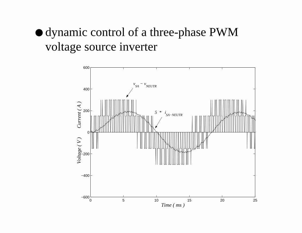
dynamic control of a three-phase PWMvoltage source inverter
0 5 10 15 20 25−600
−400
−200
0
200
400
600
Time ( ms )
Vo
ltag
e (
V )
C
urr
en
t (
A )v
SA − v
NEUTR
5 * iSA−NEUTR

dynamic control of a three-phase PWMvoltage source inverter
0 5 10 15 20 25−60
−40
−20
0
20
40
60
Time ( ms )
Vo
ltag
e (
V )
C
urr
en
t (
A )
iSA−NEUTR
iSB−NEUTR
iSC−NEUTR
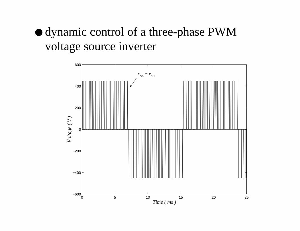
dynamic control of a three-phase PWMvoltage source inverter
0 5 10 15 20 25−600
−400
−200
0
200
400
600
Time ( ms )
Vo
ltag
e (
V )
vSA
− vSB

Main Contributions
development of a “simultaneous solution for linearand nonlinear control and power systemequations” (SSCPS) in EMTP-based programs(with NO time step delay as the existing in TACSsince 1977). A “circuit approach” was proposed inthis thesis;

Main Contributions
experimental implementation in MicroTran (theUBC version of the EMTP), based on SSCPS, of asimultaneous solution for:
9 linear and nonlinear current and voltage dependentsources ; transfer functions; hard and soft limiters;mathematical and transcendental FORTRANfunctions; special control devices; transformation ofvariables; voltage-controlled switches
9 nonlinear model of a diode semiconductor
Main Contributions
development of the subroutine “GATE” inMicroTran, allowing the dynamic control of theturn-on and turn-off times of semiconductor devices
development of power electronics simulation casesin MicroTran, with SSCPS and GATE
Recommendations for future work
automatic calculation of initial conditions
frequency response of integrated control andpower system equations
detailed nonlinear models of semiconductor devices
generic nonlinear dependent sources
voltage and frequency dependent aggregated loadmodels
models for FACTS and Custom Power devices
Conclusions
New EMTP models for control and powerelectronic devices for electric power qualityassessment were developed in this Ph.D. thesisproject.
EMTP simulations offer theoretical and practicalinsights into the evaluation of power quality, both bytime-domain simulation techniques and byfrequency-domain simulation techniques.
The technical impact of power electronic deviceson the quality of power can be evaluated with themodels developed in this work.