Embed Size (px)
Citation preview

First published in August 1998
National Pollutant Inventory
Emissions EstimationTechnique Manual
for
Printing, Publishing, andPackaging
Approved 25/6/98 2
EMISSION ESTIMATION TECHNIQUESFOR
PRINTING, PUBLISHING, AND PACKAGING
TABLE OF CONTENTS
1.0 INTRODUCTION ......................................................................................................4
2.0 PROCESS DESCRIPTION.........................................................................................5
2.1 Industrial Processes in the Printing, Publishing, andPackaging Industry......................................................................................5
2.2 Rotogravure Printing .................................................................................52.3 Flexographic Printing .................................................................................72.4 Offset Lithographic Printing......................................................................72.5 Letterpress Printing.....................................................................................92.6 Screen Printing...........................................................................................112.7 Plateless Printing .......................................................................................11
3.0 EMISSION SOURCES IN THE PRODUCTION LINE ......................................11
4.0 FACTORS INFLUENCING EMISSIONS............................................................18
4.1 Process Operating Factors.........................................................................184.2 Rotogravure Printing ...............................................................................184.3 Flexographic Printing ...............................................................................184.4 Offset Lithographic Printing....................................................................194.5 Letterpress Printing..................................................................................194.6 Screen Printing...........................................................................................194.7 In-Process Fuel ...........................................................................................204.8 Storage Tanks .............................................................................................20
5.0 EMISSION ESTIMATION......................................................................................20
5.1 Emissions To Air.......................................................................................215.2 Emissions To Water..................................................................................215.3 Emissions To Land....................................................................................225.4 Total VOC Emissions From The Press..................................................225.5 Speciating Total VOC Emissions............................................................24
6.0 EMISSION FACTOR RATING .............................................................................25
7.0 CONTROL TECHNOLOGIES ................................................................................26
8.0 REFERENCES ...........................................................................................................28
APPENDIX I ....................................................................................................................29
Approved 25/6/98 3
PRINTING, PUBLISHING, AND PACKAGING
LIST OF FIGURES &TABLES
Figure 1. Flow Chart for a Typical 8-Colour Gravure Printing Press..................6
Figure 2. Offset Lithography Printing Line Emission Points................................8
Figure 3. Letterpress Printing Line Emission Points............................................10
Table 1. Substances Typically Emitted by Printing Activities...........................12
Table 2. Rotogravure Raw Material Inputs and Pollutant Outputs................13
Table 3. Flexography Raw Material Inputs and Pollutant Outputs.................14
Table 4. Lithography Raw Material Inputs and Pollutant Outputs.................15
Table 5. Letterpress Raw Material Inputs and Pollutant Outputs ...................16
Table 6. Screen Printing Raw Material Inputs and Pollutant Outputs...........17
Table 7. Estimated Control Technology Efficiencies for Printing Lines.........27

Approved 25/6/98 4
1.0 Introduction
The purpose of all Emission Estimation Techniques (EET) Manuals in thisseries is to assist Australian manufacturing, industrial, and service facilities toreport emissions of listed substances to the National Pollutant Inventory(NPI). This Manual describes the procedures and recommended approachesfor estimating emissions from facilities engaged in printing, packaging, andpublishing activities.
The printing activities covered in this Manual apply to facilities primarilyusing the following printing methods :
• Rotogravure Packaging, advertising, greeting cards, art books,catalogues, and directories
• Flexography Packaging, advertising newspapers, books,magazines, financial and legal documentdirectories
• Offset Lithography Magazines, catalogues, and directories, newspapers,books, stationery, financial and legal documents,advertising, journals, packaging, food, beverageand aerosol cans
• Letterpress Magazines, catalogues, and directories, newspapers,books, stationery, financial and legal documents,advertising, journals, packaging, food, beverageand aerosol cans
• Screen Signs, electronics, wallpaper, greeting cards,ceramics, decals, banners, plastic bottles
EET MANUAL: Printing, Publishing, and Packaging
HANDBOOK: Printing, Publishing, and Services to Printing
ANZSIC CODE : 241 (including 2411, 2412, 2413), and 242 (including2421, 2422, 2423)
This Manual was drafted by the NPI Unit of the Queensland Department ofEnvironment on behalf of the Commonwealth Government. It has beendeveloped through a process of national consultation involving State andTerritory environmental authorities and key stakeholders, and has beenconsidered by independent reviewers.
Approved 25/6/98 5
2.0 Process Description
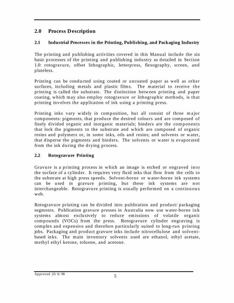
2.1 Industrial Processes in the Printing, Publishing, and Packaging Industry
The printing and publishing activities covered in this Manual include the sixbasic processes of the printing and publishing industry as detailed in Section1.0: rotogravure, offset lithographic, letterpress, flexography, screen, andplateless.
Printing can be conducted using coated or uncoated paper as well as othersurfaces, including metals and plastic films. The material to receive theprinting is called the substrate. The distinction between printing and papercoating, which may also employ rotogravure or lithographic methods, is thatprinting involves the application of ink using a printing press.
Printing inks vary widely in composition, but all consist of three majorcomponents: pigments, that produce the desired colours and are composed offinely divided organic and inorganic materials; binders are the componentsthat lock the pigments to the substrate and which are composed of organicresins and polymers or, in some inks, oils and resins; and solvents or water,that disperse the pigments and binders. The solvents or water is evaporatedfrom the ink during the drying process.
2.2 Rotogravure Printing
Gravure is a printing process in which an image is etched or engraved intothe surface of a cylinder. It requires very fluid inks that flow from the cells tothe substrate at high press speeds. Solvent-borne or water-borne ink systemscan be used in gravure printing, but these ink systems are notinterchangeable. Rotogravure printing is usually performed on a continuousweb.
Rotogravure printing can be divided into publication and product/packagingsegments. Publication gravure presses in Australia now use water-borne inksystems almost exclusively to reduce emissions of volatile organiccompounds (VOCs) from the press. Rotogravure cylinder engraving iscomplex and expensive and therefore particularly suited to long-run printingjobs. Packaging and product gravure inks include nitrocellulose and solvent-based inks. The main inventory solvents used are ethanol, ethyl acetate,methyl ethyl ketone, toluene, and acetone.
Approved 25/6/98 6
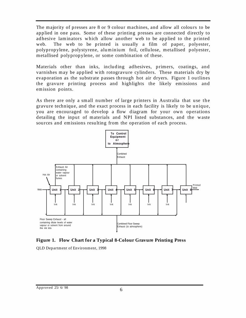
The majority of presses are 8 or 9 colour machines, and allow all colours to beapplied in one pass. Some of these printing presses are connected directly toadhesive laminators which allow another web to be applied to the printedweb. The web to be printed is usually a film of paper, polyester,polypropylene, polystyrene, aluminium foil, cellulose, metallised polyester,metallised polypropylene, or some combination of these.
Materials other than inks, including adhesives, primers, coatings, andvarnishes may be applied with rotogravure cylinders. These materials dry byevaporation as the substrate passes through hot air dryers. Figure 1 outlinesthe gravure printing process and highlights the likely emissions andemission points.
As there are only a small number of large printers in Australia that use thegravure technique, and the exact process in each facility is likely to be unique,you are encouraged to develop a flow diagram for your own operationsdetailing the input of materials and NPI listed substances, and the wastesources and emissions resulting from the operation of each process.
To ControlEquipment
o rto Atmosphere
Unit 1 Unit 2 Unit 3 Unit 4 Unit 5 Unit 6 Unit 8Unit 7
CombinedExhaust
Exhaust Aircontainingwater vapouror solventfumes
Hot Air
Web
Ink Ink Ink InkInkInk Ink
Combined Floor SweepExhaust (to atmosphere)
Floor Sweep Exhaust - allcontaining dilute levels of watervapour or solvent from aroundthe ink kits
PrintedWeb
Figure 1. Flow Chart for a Typical 8-Colour Gravure Printing Press
QLD Department of Environment, 1998
Approved 25/6/98 7
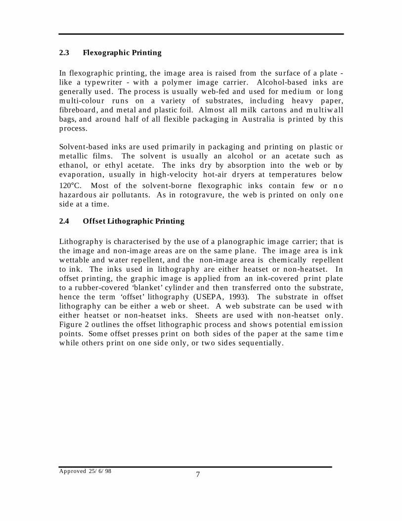
2.3 Flexographic Printing
In flexographic printing, the image area is raised from the surface of a plate -like a typewriter - with a polymer image carrier. Alcohol-based inks aregenerally used. The process is usually web-fed and used for medium or longmulti-colour runs on a variety of substrates, including heavy paper,fibreboard, and metal and plastic foil. Almost all milk cartons and multiwallbags, and around half of all flexible packaging in Australia is printed by thisprocess.
Solvent-based inks are used primarily in packaging and printing on plastic ormetallic films. The solvent is usually an alcohol or an acetate such asethanol, or ethyl acetate. The inks dry by absorption into the web or byevaporation, usually in high-velocity hot-air dryers at temperatures below120°C. Most of the solvent-borne flexographic inks contain few or nohazardous air pollutants. As in rotogravure, the web is printed on only oneside at a time.
2.4 Offset Lithographic Printing
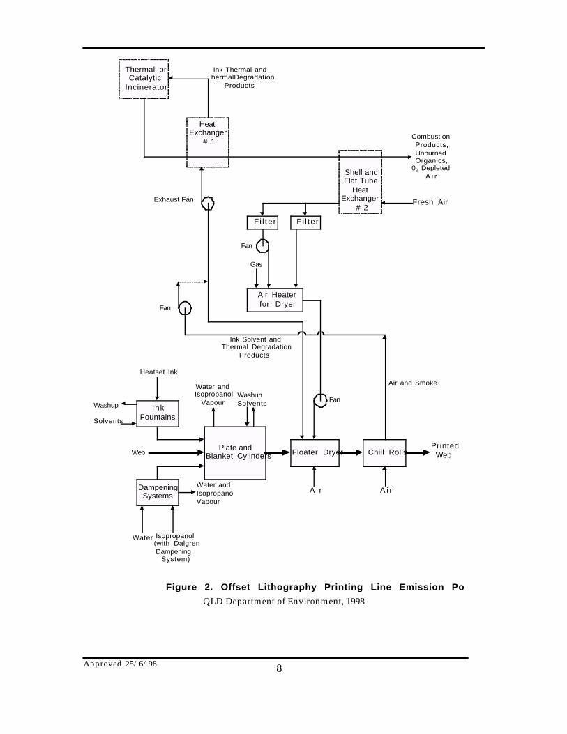
Lithography is characterised by the use of a planographic image carrier; that isthe image and non-image areas are on the same plane. The image area is inkwettable and water repellent, and the non-image area is chemically repellentto ink. The inks used in lithography are either heatset or non-heatset. Inoffset printing, the graphic image is applied from an ink-covered print plateto a rubber-covered ‘blanket’ cylinder and then transferred onto the substrate,hence the term ‘offset’ lithography (USEPA, 1993). The substrate in offsetlithography can be either a web or sheet. A web substrate can be used witheither heatset or non-heatset inks. Sheets are used with non-heatset only.Figure 2 outlines the offset lithographic process and shows potential emissionpoints. Some offset presses print on both sides of the paper at the same timewhile others print on one side only, or two sides sequentially.
Approved 25/6/98 8
Thermal orCatalytic
Incinerator
HeatExchanger
# 1
Shell andFlat Tube
HeatExchanger
# 2
Fi l terF i l te r
Air Heaterfor Dryer
CombustionProducts,UnburnedOrganics,
02 DepletedA i r
Fresh Air
Gas
Fan
InkFountains
DampeningSystems
Plate andBlanket Cylinders Floater Dryer Chill Rolls
WashupSolvents
Water andIsopropanol
Vapour
Heatset Ink
Washup
Solvents
Web
Water Isopropanol(with DalgrenDampening
System)
Water andIsopropanolVapour
A i r A i r
PrintedWeb
Air and Smoke
Fan
Ink Solvent andThermal Degradation
Products
Fan
Figure 2. Offset Lithography Printing Line Emission Poi
Exhaust Fan
Ink Thermal andThermalDegradation
Products
QLD Department of Environment, 1998
Approved 25/6/98 9
An aqueous solution of isopropyl alcohol is commonly used to dampen thenon-image area on the plate, and is called the ‘fountain’ or ‘dampening’solution. The fountain solution in offset lithographic printing hastraditionally contained about 15 percent alcohol although there are timeswhen up to 30 percent alcohol can be used. Because of environmentalconcerns, the use of isopropyl alcohol is decreasing. Fountain solutionscontaining less VOCs, or alcohol substitutes are gaining acceptance within theindustry in Australia. The newspaper industry in particular is nowpredominantly using alcohol substitutes.
Offset lithographers also use cleaning solutions to clean the press andmachine parts. These cleaning solutions have traditionally contained highsolvent solutions (90 to 100 percent). Some lower or non-solvent cleaners arenow becoming available, in which the solvent content ranges from zero to 30percent.
2.5 Letterpress Printing
Letterpress printing is the oldest form of movable type printing. Likeflexography, letterpress printing uses a relief printing plate and viscous inkssimilar to lithographic inks. Various types of letterpress plates are available.These plates differ from flexographic plates in that they have a rigid backing, -usually metal or plastic, and are not ‘flexible’. Both sheet-fed and web pressesare in use. Web letterpress equipment uses heatset and non-heatset inks.Letterpress printing uses no fountain solutions, and the cleaning solvents aresimilar to those used in lithography. Letterpress printing once dominatedperiodical and newspaper publishing, however, the majority of newspapersin Australia have now converted to non-heatset web offset printing.
Letterpress printing uses a paper web that is printed on both sides (one side ata time), and uses heatset inks (usually of about 40 percent by volume solvent).The web is dried after each colour is applied. Heatset letterpress ink is similarto heatset lithographic ink. These inks contain resins dissolved in aliphatichydrocarbons (alkenes), and are dried in hot-air ovens.
‘Moisture-set’ inks used in some packaging applications contain trimethyleneglycol, which is a hazardous air pollutant. ‘Water-washable’ letterpress inksare sometimes used for printing paper and corrugated boxes, and these inkscontain glycol-based solvents that may contain listed substances. Figure 3shows the letterpress schematic and potential emission points along theprinting line.

Approved 25/6/98 10
ThermalIncinerator
HeatExchanger
# 1
RotaryHead #2
Exchanger
F i l ter F i l te r
Air Heaterfor Dryer
CatalyticIncinerator
PressTunnel orFloaterDryer
Chil l Rolls
Gas
CombustionProducts,UnburnedOrganics,
O2 DepletedA i r
Fresh AirExhaust Fan
Fan Gas
GasSupply
FanFan
Only WhenCatalytic UnitIs Used Here
Solvent and ThermalDegradationProducts
Heatset Ink
Printed Web
Air and Smoke
Cool WaterA i rA i r
Washup
Solvents
Web
Figure 3. Letterpress Printing Line Emission Points
QLD Department of Environment, 1998
Approved 25/6/98 11
2.6 Screen Printing
Screen printing involves forcing ink through a stencil in which the imageareas are porous. The screens are generally made of silk, nylon, or metalmesh. Screen printing is used for signs, displays, electronics, wallpaper,greeting cards, ceramics, decals, banners, and textiles. Most screen printingwork in Australia is conducted on textiles. Ink systems used in screenprinting include ultra-violet cure, water-borne, solvent-borne, and plastisol(polyvinyl chloride), which is mainly used in textile printing. Solvent-basedink systems contain aliphatic, aromatic, and oxygenated organic solvents.
Both sheet-fed and web presses are used in screen printing. The substrate canbe dried after each printing station or, in the case of absorbent substrates, afterall colours are printed. Solvent and water-borne inks are dried in hot-air orinfra-red drying ovens. Dryer gases are partially recycled and partially vented.
2.7 Plateless Printing
This technology is a relatively new process used primarily for short runs onpaper substrates. Plateless printing processes include electronic (laserprinting), electrostatic (photocopiers), magnetic, thermal (facsimilemachines), and ink-jet printing. Plateless printing processes account for onlya small fraction of printing activity. Electrostatic toners and ink-jet printerinks may contain listed substances.
3.0 Emission Sources In The Production Line
The predominant emissions from the printing industry are volatile organiccompounds (VOCs) contained in the printing inks, fountain solutions, andcleaning solutions. Some of these VOCs are likely to be listed substances withemissions requiring NPI reporting. VOCs can also be emitted from bindingand laminating operations.
In printing processes, the solvent or water evaporates from the ink into theatmosphere during a drying stage. Ultraviolet inks may be also used i nprinting operations, although no emissions are occurring in this case.
Emissions from proofing presses, cleaning operations, ink storage tanks, andink mixing operations are relatively minor compared to the emissions thatoccur during a printing process, but they do contribute to overall emissions.
Approved 25/6/98 12
Other listed substances, including sulphur dioxide, carbon monoxide, andparticulate matter, are emitted from combustion sources.
The Combustion in Boilers Manual should be available from your local Stateor Territory environmental authorities This Manual is designed to provideguidance on estimating emissions from combustion sources using a widevariety of fuels and combustion equipment including low-temperature ovensand driers.
The six printing processes identified in the previous Section have manycommon emissions, although there are emissions that are process specific.Table 1 identifies likely emissions of listed substances common to allprocesses, while Tables 2 to 6 outline potential emissions for each of thedifferent printing processes.
Table 1. Substances Typically Emitted by Printing Activities
♦ acetone ♦ n-butyl alcohol♦ ethyl acetate ♦ n-propyl alcohol♦ ethanol ♦ phosphoric acid♦ isopropyl alcohol ♦ styrene (ethyl benzene)♦ methyl ethyl ketone ♦ toluene (methylbenzene)♦ methyl isobutyl ketone ♦ xylenes (individual or mixed isomers)♦ propyl acetate♦ butanol
♦ particulate matter (PM10)♦ 2-Butoxyethanol
QLD Department of Environment, 1998
Approved 25/6/98 13
Table 2. Rotogravure Raw Material Inputs and Pollutant Outputs
Process Inputs Outputs
Imaging Photographicprocessing solution
May contain volatile organic compounds andcontribute to air emissions. Waste solutions.
Wash Water Used rinse water.
Cleaning Solutions Rags containing solvents (sent to laundry service,disposed of as hazardous waste, or treated on oroff-site to recover solvents).
Chemical StorageContainers
Empty containers (disposed of or returned tosuppliers) containing residue listed substances.
CylinderMaking
Acid etching solution Waste solutions containing listed substances towater or sewer.
Printing Ink Solvent-based inks (toluene-based for mass-circulation printing and alcohol-based forpackaging) maintain the required low viscosity andcontribute to air emissions. Waste ink disposed ofas hazardous waste.
Heat Ovens are used to drive off the solvents to dry theink. Ink solvents can be recaptured throughabatement and control equipment.
Cleaning Solutions Solvents used to remove excess ink contribute toair emissions.
Finishing Adhesives Possible losses to the air.
Adapted from Profile of the Printing and Publishing Industry, USEPA 1995.
Approved 25/6/98 14
Table 3. Flexography Raw Material Inputs and Pollutant Outputs
Process Inputs Outputs
Imaging Developer May contain volatile organic compounds andcontribute to air emissions. Spent developer(transferred to waste treatment).
Fixer May be volatile and contribute to air emissions.Silver from film is often electrolytically recoveredfrom the fixer prior to transfer of spent fixer tosewer).
Wash Water Used rinse water.
Cleaning Solutions Rags containing solvents (sent to laundry service,disposed of as hazardous waste, or treated on oroff-site to recover solvents).
Chemical StorageContainers
Empty containers (disposed of or returned tosuppliers) containing residue listed substances.
Platemaking Plate mould Used moulds, engravings and washes.
Rubber plate Used plates, defective plates and photopolymer.
Etching and wash-outsolutions
Waste solution and spent solvents.
Printing Ink Waste ink disposed of as hazardous waste.
Solvent-based inks contribute to air emissions.
Heat Alcohol content of some inks contribute to
air emissions as ink dries. Water-based inks
are used for paper and some films.
Cleaning Solutions Solvents used to remove excess ink contribute to airemissions and hazardous wastes.
Finishing Adhesives Possible losses to the air.
Adapted from Profile of the Printing and Publishing Industry, USEPA 1995.
Approved 25/6/98 15
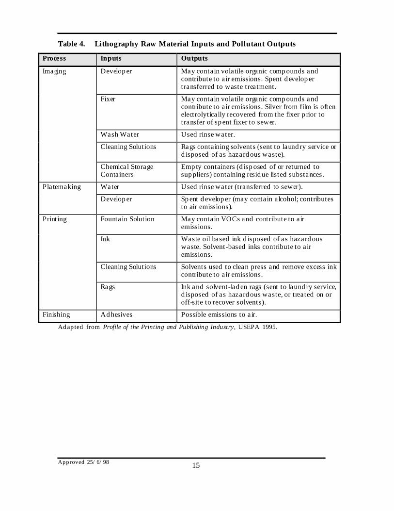
Table 4. Lithography Raw Material Inputs and Pollutant Outputs
Process Inputs Outputs
Imaging Developer May contain volatile organic compounds andcontribute to air emissions. Spent developertransferred to waste treatment.
Fixer May contain volatile organic compounds andcontribute to air emissions. Silver from film is oftenelectrolytically recovered from the fixer prior totransfer of spent fixer to sewer.
Wash Water Used rinse water.
Cleaning Solutions Rags containing solvents (sent to laundry service ordisposed of as hazardous waste).
Chemical StorageContainers
Empty containers (disposed of or returned tosuppliers) containing residue listed substances.
Platemaking Water Used rinse water (transferred to sewer).
Developer Spent developer (may contain alcohol; contributesto air emissions).
Printing Fountain Solution May contain VOCs and contribute to airemissions.
Ink Waste oil based ink disposed of as hazardouswaste. Solvent-based inks contribute to airemissions.
Cleaning Solutions Solvents used to clean press and remove excess inkcontribute to air emissions.
Rags Ink and solvent-laden rags (sent to laundry service,disposed of as hazardous waste, or treated on oroff-site to recover solvents).
Finishing Adhesives Possible emissions to air.
Adapted from Profile of the Printing and Publishing Industry, USEPA 1995.

Approved 25/6/98 16
Table 5. Letterpress Raw Material Inputs and Pollutant Outputs
Process Inputs Outputs
Imaging Developer May contain volatile organic compounds andcontribute to air emissions. Spent developertransferred to waste treatment.
Fixer May contain volatile organic compounds andcontribute to air emissions. Silver from film is oftenelectrolytically recovered from the fixer prior totransfer of spent fixer to sewer.
Wash Water Used rinse water.
Cleaning Solutions Rags containing cleaning solvents (sent to laundryservice, disposed of as hazardous waste, ortreated on or off-site to recover solvents).
Chemical StorageContainers
Empty containers (disposed of or returned tosuppliers) containing residue listed substances.
Platemaking Plate developersolution
Waste solutions may contain listed substances.
Printing Ink Waste ink transferred as hazardous waste.Solvent-based inks contribute to air emissions.
Cleaning Solutions Solvents used to remove excess ink contribute toair emissions.
Finishing Adhesives Possible losses to the air.
Adapted from Profile of the Printing and Publishing Industry, USEPA 1995.
Approved 25/6/98 17
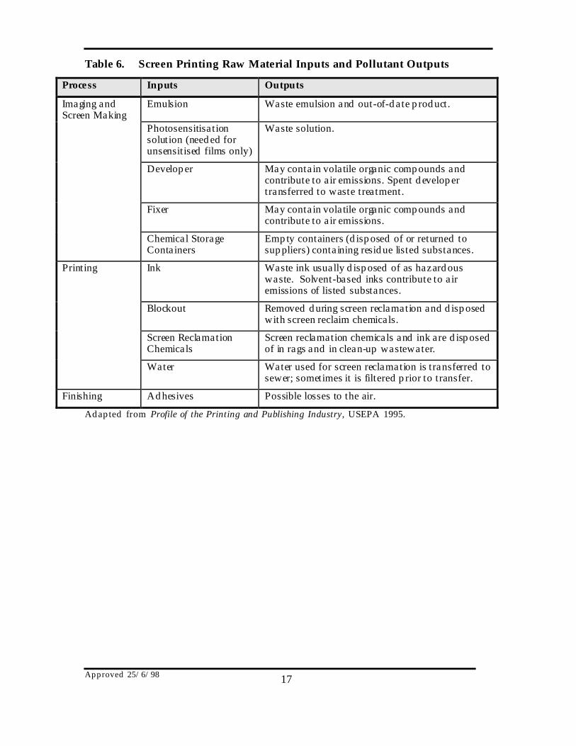
Table 6. Screen Printing Raw Material Inputs and Pollutant Outputs
Process Inputs Outputs
Imaging andScreen Making
Emulsion Waste emulsion and out-of-date product.
Photosensitisationsolution (needed forunsensitised films only)
Waste solution.
Developer May contain volatile organic compounds andcontribute to air emissions. Spent developertransferred to waste treatment.
Fixer May contain volatile organic compounds andcontribute to air emissions.
Chemical StorageContainers
Empty containers (disposed of or returned tosuppliers) containing residue listed substances.
Printing Ink Waste ink usually disposed of as hazardouswaste. Solvent-based inks contribute to airemissions of listed substances.
Blockout Removed during screen reclamation and disposedwith screen reclaim chemicals.
Screen ReclamationChemicals
Screen reclamation chemicals and ink are disposedof in rags and in clean-up wastewater.
Water Water used for screen reclamation is transferred tosewer; sometimes it is filtered prior to transfer.
Finishing Adhesives Possible losses to the air.
Adapted from Profile of the Printing and Publishing Industry, USEPA 1995.
Approved 25/6/98 18
4.0 Factors Influencing Emissions
4.1 Process Operating Factors
The type of printing and ink used are the most important process operatingfactors for estimating emissions from printing operations. The next mostimportant process operating factor affecting emissions is the productionvolume (ie. the amount of material printed as area times length), and thiswill be the determining factor in the relative magnitude of emissions. Theamount of ink used per unit of substrate (ie. the relative amount of inkedversus non-inked areas) is determined by the type of product (eg. newspaper,cereal box, birthday card, etc), and is another important factor
The following process variables relate to specific types of printing oroperations common to all types.
4.2 Rotogravure Printing
In packaging rotogravure printing, the inks contain from 55 to 80 percent byvolume low boiling-point solvent with low viscosities. It is important thatthe ink or other coating dries quickly between each colour, so the ink vehiclemust be evaporated between stations. NPI listed organic solvents (includingtoluene and methyl ethyl ketone) and alcohols are commonly used as thevolatile portion of the ink, but water-based inks are becoming more popularbecause of lower potential for worker and environmental harm. However,most presses are not compatible for use with both systems because water-based inks require a greater equipment drying capacity as well as a differentcell design.
Although rotogravure inks already contain solvents, additional solvents maybe mixed into the ink to obtain the desired viscosity.
4.3 Flexographic Printing
The ink used in flexography is of low viscosity because the ink must be fluidto print properly. Most flexographic printing (including all flexographicnewspaper and corrugated carton printing) is done with water-borne inks, butalcohol or other low-viscosity, volatile liquids are also used as the ink base.Solvents used must be compatible with the polymeric plates, so aromaticsolvents are not used. Some of the components of solvent-based flexographicink include ethanol, n-propyl alcohol, isopropyl alcohol, and acetates.

Approved 25/6/98 19
When flexography is used to print corrugated board and most paperboard,water-based inks can be used. However, fast-drying inks are required forplastic films so that the web can be rewound or processed into the finalproduct at the end of the press. When printing pressure-sensitive labels, theink must dry quickly without penetration.
4.4 Offset Lithographic Printing
The solvents (high-boiling temperature petroleum oils >150°C) in heatsetinks are driven away in a hot air or direct-flame dryer (150-200°C) to set theink. Non-heatset inks dry by adsorption or oxidation and are not releasedfrom the substrate under normal conditions. Approximately 20 to 40 percentof the solvent remains in the substrate with heatset inks, increasing to 95 to100 percent when using non-heatset inks.
Emissions from the fountain solution will depend on whether alcohol ornon-alcohol additives are used. The concentration of VOCs in the fountainsolution can vary from one facility another, and from one job to anotherwithin a facility.
Solvents used for press clean-up are usually kerosene-type high boiling-pointhydrocarbons sometimes mixed with detergents. These materials can containup to 100 percent VOCs. Low-VOC cleaning solutions are also in use i nwhich the VOC content is less than 70 percent (and can be less than 30 percentVOCs).
4.5 Letterpress Printing
Only web presses using solvent-borne inks are sources of emissions in thisindustry. Letterpress newspaper and sheet-fed printing use oxidative dryinginks and are not a source of emissions. Cleaning solutions are used with allletterpress operations.
4.6 Screen Printing
Ink systems used in screen printing include ultra-violet cure, water-borne,solvent-borne, and plastisol (polyvinyl chloride), with the latter used mainlyin textile printing. Solvent-based ink systems contain aliphatic, aromatic, andoxygenated organic solvents.

Approved 25/6/98 20
4.7 In-Process Fuel
Fuels including natural gas, oil, and electricity are used to operate the dryersused in heatset offset lithography, heatset letterpress, gravure, andflexography. A boiler may be used to generate steam for steam and water-based flexography, and to regenerate the activated carbon beds used as controldevices. Combustion byproducts include particulate matter (PM10), sulphurdioxide, nitrogen oxides, carbon monoxide, and VOCs. These are all listedsubstances that require reporting. As previously mentioned, the Combustionin Boilers Manual will be available to assist in estimating emissions from fuelburning activities.
4.8 Storage Tanks
Printing operations may use storage tanks for inks, solvents, and otherorganic substances such as fuel. To assist you in estimating emissions fromthese sources, the Fuel and Organic Liquid Storage Manual will be availablefrom your local environmental authority.
5.0 Emission Estimation
Estimates of emissions of listed substances to air, water and land should bereported for each substance that triggers a threshold. The reporting list anddetailed information on thresholds are contained in The NPI Guide at thefront of this Handbook.
In general, there are four types of emission estimation techniques (EETs) thatmay be used to estimate emissions from your facility. These are described i nThe NPI Guide. Select the EET, or mix of EETs, which is most appropriate foryour purposes. If you estimate your emission by using any of these EET’s,your data will be displayed on the NPI database as being of ‘acceptablereliability’. Similarly, if your relevant environmental authority has approvedthe use of emission estimation techniques that are not outlined in thisHandbook, your data will also be displayed as being of ‘acceptable reliability’.
For example, you might choose to use a mass balance to best estimate fugitivelosses from pumps and vents, direct measurement for stack and pipeemissions, and emission factors when estimating losses from storage tanksand stockpiles.

Approved 25/6/98 21
You are able to use emission estimation techniques that are not outlined inthis document. You must, however, seek the consent of your relevantenvironmental authority. For example, if you already undertake directmeasurement, you may use this information for NPI reporting purposes (ifyou do not undertake direct measurement, the NPI does not require you to doso).
5.1 Emissions To Air
Air emissions may be categorised as :
Fugitive emissions
These are emissions that are not released through a vent or stack. Examplesof fugitive emissions include dust from stockpiles, volatilisation of vapourfrom vats or open vessels, and material handling. Emissions emanatingfrom ridgeline roof-vents, louvres, and open doors of a building as well asequipment leaks, and leaks from valves and flanges are also examples offugitive emissions. Emission factor EETs are the usual method fordetermining losses through fugitive emissions.
Point source emissions
These emissions are exhausted into a vent or stack and emitted through asingle point source into the atmosphere. An air emissions control devicesuch as a carbon adsorption unit, scrubber, baghouse, or afterburner may beadded to the stack prior to the atmospheric release.
5.2 Emissions To Water
Emissions of substances to water can be categorised as discharges to:• Surface waters (eg. lakes, rivers, dams, and estuaries);• Coastal or marine waters; and• Stormwater.
The discharge of listed substances to a sewer or tailings dam does not requireyou to report to the NPI (See also Section 3.0 of The NPI Guide). The mainsource of wastewater from this industry is usually from air pollution controlequipment such as wet scrubbers.

Approved 25/6/98 22
The most appropriate method for determining emissions to the environmentvia wastewater is to use direct measurement, however, you may use otherEETs for the purposes of reporting to the NPI.
5.3 Emissions To Land
Emissions of substances to land on-site include solid wastes, slurries,sediments, spills and leaks, storage and distribution of liquids, and the use ofchemicals to control various elements of the environment where theseemissions contain listed substances. These emission sources can be broadlycategorised as :
• surface impoundments of liquids and slurries• unintentional leaks and spills.
5.4 Total VOC Emissions From The Press
The most appropriate method for estimating emissions of NPI listedsubstances from printing activities is a facility mass balance. Using industry-wide emission factors will not, in most cases, provide an accurate reflection ofthe actual emissions from any facility because of the wide range of operationalpractices within the industry. Operational activities that are process andfacility-specific include :
• the range and mix of printing process activities that occur at a facility; • the amount of inks, fountain solutions, and cleaning solutions used at
the facility; • the VOC content and weight percentage of listed substances in the inks,
fountain solutions, and cleaning solutions used; • the amount of ink that is recycled, but not reused, within the facility;
and, • the control equipment used, and the efficiency of this equipment.
In conducting a mass balance for a printing operation, it is important to factorinto your equation that the amount of VOCs emitted during printing (thevolatile fraction) is not always equivalent to the measured or estimated VOCcontent of the raw material. This is particularly relevant for offset

Approved 25/6/98 23
lithographic printing processes. Although non-heatset lithographic inks maycontain significant VOCs, only 2 percent of the total are emitted duringprinting, while the rest is retained in the substrate.
Equation 1 will assist you to estimate total uncontrolled emissions for eachlisted substance (S) contained in ink, fountain solution, or cleaning solutionfrom each type of printing operation (P).
Equation 1. Emissions of Listed Substances From Uncontrolled Presses
Total Amount Volatile Amount
Uncontrolled = Σ [ ( Ink Used P ) X ( Fraction S,P ) - ( Recycled P ) ] EmissionsS
Amount Fountain Volatile Amount
+ Σ [ ( Solution Used P ) X ( Fraction S,P ) - ( Recycled P ) ] Amount Cleaning Volatile Amount
+ Σ [ ( Solution Used P ) X ( Fraction S,P ) - ( Recycled P ) ]Equation 2 will assist you to estimate total controlled emissions for each listedsubstance (S) contained in ink, fountain solution, or cleaning solution fromeach type of printing operation (P).
Equation 2. Emissions of Listed Substances From Controlled Presses
Total Amount Volatile Amount
Controlled = Σ [ {( Ink Used P ) X ( Fraction S,P ) - ( Recycled P )} X ( 1 - CEI ÷ 100 )]EmissionsS
Amount Fountain Volatile Amount
+ Σ [ {( Solution Used P ) X ( Fraction S,P ) - ( Recycled P )} X ( 1 - CEFS ÷ 100 )] Amount Cleaning Volatile Amount
+ Σ [ {( Solution Used P ) X ( Fraction S,P ) - ( Recycled P )} X ( 1 - CECS ÷ 100 )]
Approved 25/6/98 24
where :
CE I = Control efficiency (percent) for each ink (I) used;
CE FS = Control efficiency (percent) for each fountain solution (FS)used; and
CE CS = Control efficiency (percent) for each cleaning solution (CS)used.
5.5 Speciating Total VOC Emissions
The above mentioned mass balance equations can be used to estimateemissions of total VOCs from the press, or for listed substance contained i nthe ink, fountain solution, or cleaning solution.
For these purposes NPI reporting, you will need to separately list and reportemissions of each listed substance contained in ink, fountain and cleaningsolutions by first determining the weight percentage of listed substance in theproducts used.
This information is often available from your ink or solvent supplier or fromthe product Material & Safety Data Sheets. If this information provides listedsolvent amounts in volume, then you will need to convert this volumeamount to weight units as shown in Equation 3.
Equation 3. Converting Volume of Solvent to Weight Units
Amount used Amount of Density factor
in kilograms = ( material (litres) ) X ( (kg/litre) )
Emission factors are not recommended for estimating emissions from theprinting industry as the processes and practices used vary significantly.Appendix I contains emission factors for can coating and printing operationswith accompanying uncertainty estimate codes for each emission factorprovided. Section 6.0 contains a discussion of the reliability, or uncertainty, ofthe emission factor codes used.
Approved 25/6/98 25
6.0 Emission Factor Rating
Every emission factor has an associated emission factor rating (EFR) code.This rating system is common to EETs for all industries and sectors andtherefore, to all Industry Handbooks. They are based on rating systemsdeveloped by the United States Environmental Protection Agency (USEPA),and by the European Environment Agency (EEA). Consequently, the ratingsmay not be directly relevant to Australian industry. Sources for all emissionfactors cited can be found in the references section of this document. Theemission factor ratings will not form part of the public NPI database.
When using emission factors, you should be aware of the associated EFR codeand what that rating implies. An A or B rating indicates a greater degree ofcertainty than a D or E rating. The less certainty, the more likely that a givenemission factor for a specific source or category is not representative of thesource type. These ratings notwithstanding, the main criterion affecting theuncertainty of an emission factor remains the degree of similarity betweenthe equipment/process selected in applying the factor, and the targetequipment/process from which the factor was derived.
The EFR system is as follows :
A - ExcellentB - Above AverageC - AverageD - Below AverageE - PoorU - Unrated
Estimating your facility’s emissions based on emission factors only, andwithout taking into account any control measures, may have an uncertaintyas high as 100%.
Other EETs, such as release calculations based on mass balance of solventconsumption and without taking into account control measures, may havean uncertainty of 50%.
An EET based on an audit or direct measurement, and taking into accountcontrol measures, may have an uncertainty of 20%.
Approved 25/6/98 26
7.0 Control Technologies
As solvents are expensive, they may be recovered and reused for economic aswell as environmental reasons. Solvent emissions can be controlled as part ofthe normal operating procedures in a printing or packaging facility. Inaddition, most manufacturing is undertaken inside facility buildings, wheresolvent losses must be minimised to protect the health of workers, andconform to occupational health and safety standards.
In recent years the printing industry in Australia has implemented severalcreative emission prevention and control techniques that improve efficiencyand increase profits, while at the same time minimising environmentalimpacts. In many facilities, using alternative ink and cleaning products withreduced VOC emissions and lowering the VOC emissions, from printing andpress clean-up, has been accomplished using vegetable oil-based or water-based inks rather than solvent-based inks. Other control technologies thathave gained wide industry acceptance include :
• improving housekeeping and better operating practices, eg. coveringreservoirs and containers, scheduling jobs according to the colour to beprinted, and using wipes as long as possible;
• reducing ink vaporisation by using diaphragm pumps which do not heatink to the same extent as mechanical vane pumps;
• recycling waste solvents on-site and off-site, as the segregation ofsolvents may allow for a secondary use such as equipment cleaning orink thinning;
• recycling of certain waste inks where possible;
• eliminating the use of chromium(VI) containing fountain solutions;
• installing automatic viscosity controllers to keep ink conditions optimal;
• using automatic cleaning equipment which can often be retrofitted toexisting presses and operations. Typically, lower volumes of cleaningformulations are applied with cleaning equipment, such that air contact,and thereby volatilisation is reduced, and most are designed to includerecycling and reuse of cleaning solutions; and
• using fountain coolers to reduce evaporation from the dampeningfountain.
Approved 25/6/98 27
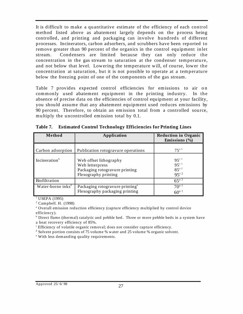
It is difficult to make a quantitative estimate of the efficiency of each controlmethod listed above as abatement largely depends on the process beingcontrolled, and printing and packaging can involve hundreds of differentprocesses. Incinerators, carbon adsorbers, and scrubbers have been reported toremove greater than 90 percent of the organics in the control equipment inletstream. Condensers are limited because they can only reduce theconcentration in the gas stream to saturation at the condenser temperature,and not below that level. Lowering the temperature will, of course, lower theconcentration at saturation, but it is not possible to operate at a temperaturebelow the freezing point of one of the components of the gas stream.
Table 7 provides expected control efficiencies for emissions to air oncommonly used abatement equipment in the printing industry. In theabsence of precise data on the efficiencies of control equipment at your facility,you should assume that any abatement equipment used reduces emissions by90 percent. Therefore, to obtain an emission total from a controlled source,multiply the uncontrolled emission total by 0.1.
Table 7. Estimated Control Technology Efficiencies for Printing Lines
Method Application Reduction in OrganicEmissions (%)
Carbon adsorption Publication rotogravure operations 75a 1
Incinerationb Web offset lithographyWeb letterpressPackaging rotogravure printingFlexography printing
95c 1
95c 1
85a 2
95c 2
Biofiltration 65a 2
Water-borne inksd Packaging rotogravure printinge
Flexography packaging printing70a 1
60a 1
1 USEPA (1995)2 Campbell. H. (1998)a Overall emission reduction efficiency (capture efficiency multiplied by control deviceefficiency).b Direct flame (thermal) catalytic and pebble bed. Three or more pebble beds in a system havea heat recovery efficiency of 85%.c Efficiency of volatile organic removal; does not consider capture efficiency.d Solvent portion consists of 75 volume % water and 25 volume % organic solvent.e With less demanding quality requirements.
Approved 25/6/98 28
8.0 References
Eastern Research Group Inc. November 1996. Graphic Arts: Final Report f orArea Sources Committee Emission Inventory Improvement Program.Morrisville, NC, USA.
EMEP/ CORINAIR. (1996). AIR: Atmospheric Emission InventoryGuidebook. Solvent and other Product Use - Printing Industry. The EuropeanEnvironment Agency, Copenhagen, Denmark.
USEPA. August 1990. Guide to Pollution Prevention - The CommercialPrinting Industry, EPA 625/7-90/008, Office of Research and Development,Washington, DC, USA.
USEPA. October 1992. VOC / PM Speciation Data System - Version 1.50.United States Environmental Protection Agency, Office of Air QualityPlanning and Standards. Research Triangle Park, NC, USA.
USEPA. January 1995a. Compilation of Air Pollutant Emission Factors,Volume 1: Stationary Point and Area Sources, fifth edition, AP-42. Section4.9.1 General Graphic Printing. United States Environmental ProtectionAgency, Office of Air Quality Planning and Standards. Research TrianglePark, NC, USA.
USEPA. January 1995a. Compilation of Air Pollutant Emission Factors,Volume 1: Stationary Point and Area Sources, fifth edition, AP-42. Section4.9.2 Publication Gravure Printing. United States Environmental ProtectionAgency, Office of Air Quality Planning and Standards. Research TrianglePark, NC, USA.
USEPA. August 1995. EPA Office of Compliance Sector Notebook Project.Profile of the Printing and Publishing Industry. United States EnvironmentalProtection Agency, Office of Enforcement and Compliance Assurance.Washington, DC, USA.
USEPA. December 1996. Fire : Factor Information Retrieval System. UnitedStates Environmental Protection Agency, Office of Air Quality Planning andStandards. Research Triangle Park, NC, USA.
Written Communication and Attachments from Heather Campbell,Containers Packaging to Tim Powe Queensland Department of Environment,Brisbane Queensland, 21 January 1998.
Written Communication and Attachments from Dr Tony Wilkins, NewsLimited to Tim Powe Queensland Department of Environment, BrisbaneQueensland, 23 January 1998.

Approved 25/6/98 29
Appendix I
Can Printing and Coating
1.0 Printing Process Description
Cans may be made from a rectangular sheet and two circular ends (3-piececans), or they can be drawn and wall ironed from a shallow cup to which anend is attached after the can is filled (2-piece cans). While the printing of bothcan types is almost identical, there are major differences in coating practices,depending on the type of can and the packaged product. Figure 1 depicts a 3-piece can sheet printing operation.
Sheet (Plate)Stacker
Wicket Oven
ApplicationRoller
Oven VarnishCoater
VarnishTray
PressureRollers
LithographCoater
Ink Applicators
BlanketCylinder
Sheet (Plate)Feeder
Figure 1. Three Piece Can Sheet Printing OperationUSEPA January 1995a. AP-42
Aluminium Can Decoration
The process of printing and coating aluminium cans has two stages: theinternal spraying of the can, and then decoration and the application oflacquer to the outside surface of the can. Internal coatings over varnish andbasecoat materials are water based, but can often contain a small percentage ofthe solvents butanol and butyl cellusolve. These solvents will evaporate i nthe curing ovens.
The actual printing process is letterpress offset which uses paste inks. Theletterpress plate transfers the ink to a blanket which then prints the cans i nthe ‘round’ allowing over 1000 cans/minute to be printed on a six colourmachine. Emissions from this printing process are negligible.
Approved 25/6/98 30
Flat Metal Decoration
The process of printing tinplate or aluminium sheets involves two majoroperations: firstly the precoating or lacquering of the plate, followed byprinting, generally using the offset lithographic process. The final print isthen given a coat of protective varnish using a machine identical to a pre-coater.
The process description of the use of plates, blankets, isopropyl alcohol, andclean-up solvents is described at Section 2.4 of this Manual. Inks may be alkydresin, polyester or UV curable types, but more frequently are the resin-based.Hot air ovens are used to dry by means of heat oxidation. Inks contain verylow levels of VOC and are unlikely to contain NPI listed solvents.
2.0 Coating Process Description
Emissions from can coating operations depend on the composition of thecoating, the coated area, thickness of coat, and, the efficiency of application.Post-application chemical changes and nonsolvent contaminants, includingoven fuel combustion products, may also affect the composition of emissions.All solvents used and not recovered can be considered potential emissions.
Sources of can coating VOC emissions include the coating area and the ovenarea of the sheet base and lithographic coating lines, the 3-piece can side seamand interior spray coating processes, and the 2-piece can coating and endsealing compound lines. Emission rates vary with line speed, can or sheetsize, and coating type. On sheet coating lines where the coating is applied byrollers, most solvent evaporates in the oven. For other coating processes, theoperation itself is the major source. Emissions can be estimated from theamount of coating applied and applying the emission factors in Table 1.
Incineration, and the use of water-borne and low solvent coatings, bothreduce organic vapour emissions. Catalytic and thermal incinerators can alsobe used. Pimers, backers (coatings on the reverse, or backside of the coil), andsome water-borne low to medium-gloss top-coats have been developed thatequal the performance of organic solvent-borne coatings for aluminium.Other feasible control options, such as electrostatically sprayed powdercoatings, are not yet available to the whole industry.
Available control technology includes the use of add-on devices likeincinerators and carbon adsorbers and a conversion to low solvent andultraviolet curable coatings. Thermal and catalytic incinerators can both be
Approved 25/6/98 31
used to control emissions from 3-piece can sheet base coating lines, sheetlithographic coating lines, and interior spray coating. Incineration isapplicable to a 2-piece can coating line. Carbon adsorption is most applicableto low temperature processes that use a limited number of solvents. Suchprocesses include 2 and 3-piece can interior spray coating, 2-piece can endsealing compounds lines, and 3-piece can side seam spray coating.
Low solvent coatings are not yet available to replace all the organic solvent-borne formulations presently used in the can industry. Water-bornebasecoats have been successfully applied to 2-piece cans. Powder coatingtechnology is used for side seam coating of non-cemented 3-piece cans.
Ultraviolet curing technology is available for rapid drying of the first twocolours of ink on 3-piece can sheet lithographic coating lines.
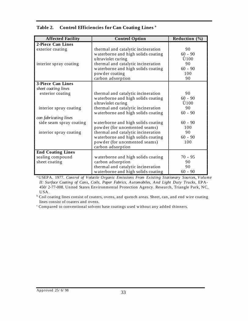
The efficiencies of various control technologies for can coating lines arepresent in Table 2.
3.0 Emission Factors for Can Coating
An emission factor is a tool that is used to estimate emissions to theenvironment. In this Manual, it relates the quantity of substances emittedfrom a source to some common activity associated with those emissions.Emission factors are obtained from US, European, and Australian sources,and are usually expressed as the weight of a substance emitted, multiplied bythe unit weight, volume, distance, or duration of the activity emitting thesubstance. For example, kilograms of VOCs emitted per hour of can coatingline operation.
Emission factors are used to estimate a facility’s emissions by the generalequation:
E = A x T x EF x [1 - (CE/100)]where :
E = emissions;A = activity rate;T = time (or another variable)EF = uncontrolled emission factor; andCE = overall emission control efficiency, %.
Emission factors developed from measurements for a coating line or canoven dryer can sometimes be used to estimate emissions at other sites. For

Approved 25/6/98 32
example, a company may have several units of similar model and size, suchthat if emissions were measured from one coating line or oven, an emissionfactor could be developed and applied to similar units. As recommendedpreviously, it is advisable to have the emission factor reviewed and approvedby your local environmental authority prior to its use for NPI estimations.
Table 1. VOC Emission Factors For Can Coating Processes a
Process
TypicalEmissions
fromCoatingLine b
(kg/hr)
EstimatedFraction
FromCoated
Area(%)
EstimatedFraction
From Oven
(%)
TypicalEmissions
ofVOCs c
(tonnes/year)
3-piece can sheetsheet base coating
51 9 - 12 88 - 91 160
3-piece can sheetlithographic coating l
30 8 - 11 89 - 92 50
3-piece beer andbeverage can - sideseam spray coating
5 100 air dried 18
3-piece beer andbeverage can -interior body spraycoating process
25 75 - 85 15 - 25 80
2-piece can coatingline
39 ND ND 260
2-piece can endsealing compoundline
4 100 air dried 14
a USEPA. 1977. Control of Volatile Organic Emissions From Existing Stationary Sources, Volume II: SurfaceCoating of Cans, Coils, Paper Fabrics, Automobiles, And Light Duty Trucks, EPA-450/2-77-008. UnitedStates Environmental Protection Agency. Research, Triangle Park, NC, USA.
b Organic solvent emissions will vary according to line speed, size of can or sheet being coated, and type ofcoating used.
c Based upon normal operating conditions. NPI reporting requires speciating total VOC emissions intoindividual listed compounds. To do this calculation, multiply the weight percentages of each individuallisted substance in the inks by the total VOC weight emissions.
Table 2 provides expected control efficiencies for emissions to air oncommonly used abatement equipment on can coating lines. To determinetotal emissions, multiply the emission obtained from using the emissionfactors in Table 1 by the reduction percentage from Table 2. For example, ifthe control efficiency relevant to your process is given as 90 percent, multiplythe uncontrolled emission total (obtained from either using the emissionfactors in Table 1, a mass balance or another EET) by 0.1.
Approved 25/6/98 33
Table 2. Control Efficiencies for Can Coating Lines a
Affected Facility Control Option Reduction (%)2-Piece Can Linesexterior coating thermal and catalytic incineration 90
waterborne and high solids coating 60 - 90ultraviolet curing Û100
interior spray coating thermal and catalytic incineration 90waterborne and high solids coating 60 - 90powder coating 100carbon adsorption 90
3-Piece Can Linessheet coating lines exterior coating thermal and catalytic incineration 90
waterborne and high solids coating 60 - 90ultraviolet curing Û100
interior spray coating thermal and catalytic incineration 90waterborne and high solids coating 60 - 90
can fabricating lines side seam spray coating waterborne and high solids coating 60 - 90
powder (for uncemented seams) 100 interior spray coating thermal and catalytic incineration 90
waterborne and high solids coating 60 - 90powder (for uncemented seams) 100carbon adsorption
End Coating Linessealing compound waterborne and high solids coating 70 - 95sheet coating carbon adsorption 90
thermal and catalytic incineration 90waterborne and high solids coating 60 - 90
a USEPA. 1977. Control of Volatile Organic Emissions From Existing Stationary Sources, VolumeII: Surface Coating of Cans, Coils, Paper Fabrics, Automobiles, And Light Duty Trucks, EPA-450/2-77-008. United States Environmental Protection Agency. Research, Triangle Park, NC,USA.
b Coil coating lines consist of coaters, ovens, and quench areas. Sheet, can, and end wire coatinglines consist of coaters and ovens.
c Compared to conventional solvent base coatings used without any added thinners.