Embed Size (px)
Citation preview
EMI U-Seams
Version 1.0
August 2001
EMI U-Seams Version 1.0
2
IMPORTANT INFORMATION AND DISCLAIMERS
1. INTEL CORPORATION (AND ANY CONTRIBUTOR) IS PROVIDING THIS INFORMATION AS A CONVENIENCE AND ACCORDINGLY MAKES NO WARRANTIES WITH REGARD TO THIS DOCUMENT. IN PARTICULAR, INTEL (AND ANY CONTRIBUTOR) DOES NOT WARRANT OR REPRESENT THAT THIS DOCUMENT OR ANY PRODUCTS MADE IN CONFORMANCE WITH IT WILL OPERATE IN THE INTENDED MANNER. NOR DOES INTEL (OR ANY CONTRIBUTOR) ASSUME RESPONSIBILITY FOR ANY ERRORS THAT THE DOCUMENT MAY CONTAIN.
2. NO REPRESENTATIONS OR WARRANTIES ARE MADE THAT ANY PRODUCT BASED IN WHOLE OR IN PART ON THE ABOVE DOCUMENT WILL BE FREE FROM DEFECTS OR SAFE FOR USE FOR ITS INTENDED PURPOSE. ANY PERSON MAKING, USING OR SELLING SUCH PRODUCT DOES SO AT HIS OR HER OWN RISK.
3. INTEL DISCLAIMS ALL LIABILITY ARISING FROM USE OF OR IN CONNECTION WITH THE INFORMATION PROVIDED IN THIS DOCUMENT, INCLUDING LIABILITY FOR INFRINGEMENT OF ANY PROPRIETARY RIGHTS RELATING TO THE INFORMATION OR THE IMPLEMENTATION OF INFORMATION IN THIS DOCUMENT. INTEL DOES NOT WARRANT OR REPRESENT THAT SUCH DEVICES OR IMPLEMENTATION WILL NOT INFRINGE SUCH RIGHTS. INTEL IS NOT OBLIGATED TO PROVIDE ANY SUPPORT, INSTALLATION OR OTHER ASSISTANCE WITH REGARD TO THE INFORMATION.
4. THE INFORMATION REFERRED TO IN THIS DOCUMENT IS INTENDED FOR STANDARD COMMERCIAL USE ONLY. CUSTOMERS ARE SOLELY RESPONSIBLE FOR ASSESSING THE SUITABILITY OF THE INFORMATION FOR USE IN PARTICULAR APPLICATIONS. THE INFORMATION IS NOT INTENDED FOR USE IN CRITICAL CONTROL OR SAFETY SYSTEMS, MEDICAL OR LIFE SAVING APPLICATIONS, OR IN NUCLEAR FACILITY APPLICATIONS.
5. NO LICENSE, EXPRESS OR IMPLIED, BY ESTOPPEL OR OTHERWISE, TO ANY INTELLECTUAL PROPERTY RIGHTS IS GRANTED HEREIN.
Copyright 2001 Intel Corporation. All rights reserved.
Version 1.0, August 2001
† Third-party brands and names are the property of their respective owners.
Revision History
Revision Document Update Date
1.0 Initial release August 2001

EMI U-Seams Version 1.0
3
Contents
1 Scope.................................................................................................................. 5 1.1 Limitations of Document ........................................................................................................5 1.2 Reference Documents...........................................................................................................6 1.3 Terminology...........................................................................................................................7
2 Overview............................................................................................................. 8 2.1 Basic U-Seam Operation.......................................................................................................9 2.2 U-Seam Design Types ..........................................................................................................10
3 Creating a U-Seam Design................................................................................ 11 3.1 EMI Performance of a U-Seam .............................................................................................11 3.2 Cost Benefit of U-Seams versus EMI Gaskets......................................................................11 3.3 U-Seam Design Considerations ............................................................................................11
3.3.1 Total Linear Distance of Seam .................................................................................11 3.3.2 Gap Geometry (U-Seam Width, Thickness of ‘L’ Section) .......................................14 3.3.3 Depth of Overlap.......................................................................................................17
3.4 Manufacturing Tolerance Considerations..............................................................................20 3.4.1 Evaluation of Worst Case U-Seam Configurations ..................................................20
3.5 General Design Considerations.............................................................................................27 3.6 Cost/Performance Tradeoff ...................................................................................................28
4 Design Requirements........................................................................................ 29 4.1 Compliance with EMC Requirements....................................................................................29 4.2 Material Options.....................................................................................................................29
EMI U-Seams Version 1.0
4
Figures 1. U-Seam Geometry Definition .............................................................................................................7 2. U-Seam Example in Chassis .............................................................................................................8 3. Basic U-Seam Operation ...................................................................................................................9 4. Standard U-Seam Design ..................................................................................................................10 5. Standard U-Seam Design with Additional Overlap ............................................................................10 6. U-Seam Length..................................................................................................................................12 7. Effect of Changing Total U-Seam Length ..........................................................................................13 8. U-Seam Width and Gap.....................................................................................................................14 9. U-Seam Width (non-parallel case).....................................................................................................14 10. Measured Effect of U-Seam Gap Size on SE..................................................................................15 11. Predicted Effect of U-Seam Gap Size on SE...................................................................................16 12. Overlap for Standard U-Seam Design .............................................................................................17 13. Diminished Overlap because of Lead-In at U-seam Design............................................................17 14. Measured Effect of U-Seam Depth of Overlap on SE .....................................................................18 15. Predicted Effect of U-Seam Depth of Overlap on SE ......................................................................19 16. U-Seam Configuration A Tolerance Analysis (1 of 2) ......................................................................21 17. U-Seam Configuration A Tolerance Analysis (2 of 2) ......................................................................22 18. U-Seam Configuration B Tolerance Analysis (1 or 2) ......................................................................24 19. U-Seam Configuration B Tolerance Analysis (2 or 2) ......................................................................25
Tables 1. Reference Documents .......................................................................................................................6 2. Tolerance Analysis of Configuration A...............................................................................................23 3. Tolerance Analysis of Configuration B...............................................................................................26
EMI U-Seams Version 1.0
5
1 Scope The purpose of this document is to provide an overview of the Electromagnetic Compatibility (EMC) design and implementation of U-seams for use in chassis enclosures. This study focuses on U-seam design recommendations above 1 GHz. Limited measurements have been carried out on U-seam panel performance below 1 GHz and resulted in similar performance as to that predicted at 1 GHz.
1.1 Limitations of Document
• The equations and trends contained in this document have been verified to be applicable to chassis sized structures. Due to the small size of the enclosure used, there is an interaction between the noise source and the enclosure itself (because of near field effect). Although no extensive studies were carried out of this effect, it is believed that this has negligible affect on the design guidelines contained within this document.
• The bulk of the analysis leading to this document was performed with no direct contact between the two halves of the assembled panels. Any incidental contact between the panels will increase the Shielding Effectiveness of a design.
• Even though some recommendations for gap and clearance for U-seams are given, the fit and tolerance of a particular design are the responsibility of the chassis designer.
• The EMI performance of U-seams has been experimentally verified up to 10 GHz. Theoretical extrapolations have been used to predict performance up to 12 GHz.
EMI U-Seams Version 1.0
6
1.2 Reference Documents
Table 1. Reference Documents
Document Title Document Number or Author
Field and Wave Electromagnetics David K. Cheng
Controlling Radiated Emissions by Design Michel Mardiguian
Noise Reduction Techniques in Electronic Systems (second edition)
Henry W. Ott

EMI U-Seams Version 1.0
7
1.3 Terminology EMC Electromagnetic Compatibility
EMI Electromagnetic Interference
SE Shielding Effectiveness
U-seam U-shaped seam designed where chassis panels join together for the purpose of containing EMI in a chassis enclosure without the aid of metalized gaskets.
Throughout this document, U-seam geometry is defined as shown in Figure 1:
Gap
Gap
T
Overlap
U-Seam Width
L-Panel
U-Panel
Gap
Gap
T
Overlap
U-Seam Width
L-Panel
U-Panel
Figure 1. U-Seam Geometry Definition
U-seam width Width of U-panel slot
T Thickness L-panel
Gap Average gap between panels, represented as (Width-T)/2.
Overlap Depth of overlap between U-panel and L-panel
Note: All dimensions throughout this document are in millimeters (mm) unless otherwise specified.

EMI U-Seams Version 1.0
8
2 Overview
The primary purpose of U-seams is to improve the ability of a chassis enclosure to contain very high frequency EMI at its seams without the need for expensive EMI gaskets. Where U-seams can be implemented, significant cost savings can result. A good design can also take advantage of the ‘snap together’ nature of U-seams to improve manufacturability, serviceability, and enclosure structural integrity. Figure 2 shows an example of a U-seam design at the perimeter of a chassis enclosure.
Figure 2. U-Seam Example in Chassis
EMI U-Seams Version 1.0
9
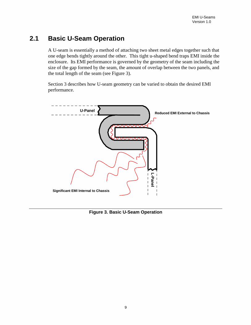
2.1 Basic U-Seam Operation
A U-seam is essentially a method of attaching two sheet metal edges together such that one edge bends tightly around the other. This tight u-shaped bend traps EMI inside the enclosure. Its EMI performance is governed by the geometry of the seam including the size of the gap formed by the seam, the amount of overlap between the two panels, and the total length of the seam (see Figure 3).
Section 3 describes how U-seam geometry can be varied to obtain the desired EMI performance.
Significant EMI Internal to Chassis
Reduced EMI External to Chassis
L-P
anel
U-Panel
Figure 3. Basic U-Seam Operation
EMI U-Seams Version 1.0
10
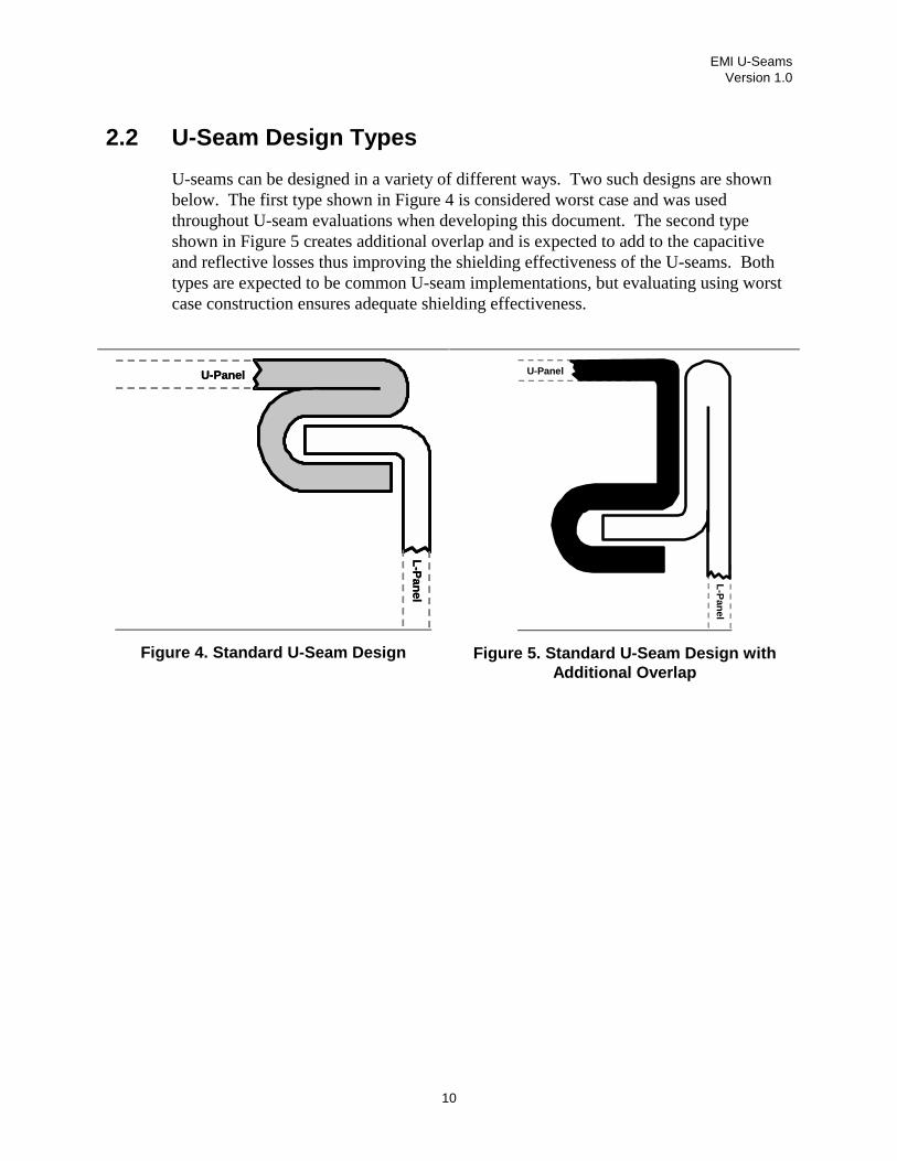
2.2 U-Seam Design Types
U-seams can be designed in a variety of different ways. Two such designs are shown below. The first type shown in Figure 4 is considered worst case and was used throughout U-seam evaluations when developing this document. The second type shown in Figure 5 creates additional overlap and is expected to add to the capacitive and reflective losses thus improving the shielding effectiveness of the U-seams. Both types are expected to be common U-seam implementations, but evaluating using worst case construction ensures adequate shielding effectiveness.
L-P
anel
U-Panel
L-P
anel
U-Panel
Figure 4. Standard U-Seam Design
L-P
anel
U-Panel
Figure 5. Standard U-Seam Design with Additional Overlap
EMI U-Seams Version 1.0
11
3 Creating a U-Seam Design
3.1 EMI Performance of a U-Seam
The metric of U-seam EMI performance is determined by its Shielding Effectiveness (SE). The Shielding Effectiveness of a U-seam represents the amount of EMI attenuation that the U-seam offers at a given frequency. This depends on several factors that include the gap size of the seam, the amount of overlap between the two panels, and the total length of the seam.
3.2 Cost Benefit of U-Seams versus EMI Gaskets
A U-seam design can present a significant cost advantage compared to that of a seam utilizing EMI gasketing. As frequencies continue to increase (and wavelengths decrease) grounding points need to be so closely spaced to provide adequate shielding that the use of continuous gaskets at seams becomes increasingly prevalent. Continuous soft gasketing and labor to install it can add significant cost, especially in larger chassis with multiple access panels.
3.3 U-Seam Design Considerations
The following sections provide details regarding the effect of the basic geometrical design parameters on U-seam EMI performance.
3.3.1 Total Linear Distance of Seam The total length of a U-seam (total perimeter distance) does not have a significant impact on the Shielding Effectiveness. A decrease in the total length by a factor of four, for example, only decreases the Shielding Effectiveness by approximately 3 dB.
Note: When estimating the shielding effectiveness of a U-seam design for an enclosure, the total perimeter length on an exposed side (the total length exposed to an antenna at one time, for example) should be considered to take the additive affect of EMI leakage through all exposed seams (relative to measurement antenna) into account.

EMI U-Seams Version 1.0
12
Figure 6 shows how the U-seam length is measured.
Length
L-Panel
U-Panel
Length
L-Panel
U-Panel
Figure 6. U-Seam Length

EMI U-Seams Version 1.0
13
The plot in Figure 7 shows the predicted effect of changing the total length by a factor of four.
Option 1 detail: U Width 1.5 mm; L Thickness 1 mm; Avg. Gap 0.25 mm; Overlap 7 mm; Total Seam Length 250 mm
Option 2 detail: U Width 1.5 mm; L Thickness 1 mm; Avg. Gap 0.25 mm; Overlap 7 mm; Total Seam Length 1000 mm
Comparative Shielding Effectiveness Plot
0
5
10
15
20
25
30
35
40
1000 2000 3000 4000 5000 6000 7000 8000 9000 10000
Frequency (MHz)
Sh
ield
ing
Eff
ecti
ven
ess
(dB
uV
/m)
250mm U-Seam Length
1000mm U-Seam Length
Figure 7. Effect of Changing Total U-Seam Length

EMI U-Seams Version 1.0
14
3.3.2 Gap Geometry (U-Seam Width, Thickness of ‘L’ Section) The gap size is the average distance between the internal wall of the U-panel and the wall of the L-panel. A decrease in the average gap size from 0.5 mm to 0.25 mm increases the Shielding Effectiveness by approximately 3 dB.
Figure 8 shows the U-seam gap geometry where the average gap is determined as (Width – T)/2.
Gap
Gap
TU-Seam Width
L-Panel
U-Panel
Gap
Gap
TU-Seam Width
L-Panel
U-Panel
Figure 8. U-Seam Width and Gap
For the case where non-parallel U-seam sides exist, the worst case U-width should be considered as shown in Figure 9 below.
U-Seam Width
U-Panel
L-Panel
Figure 9. U-Seam Width (non-parallel case)
EMI U-Seams Version 1.0
15
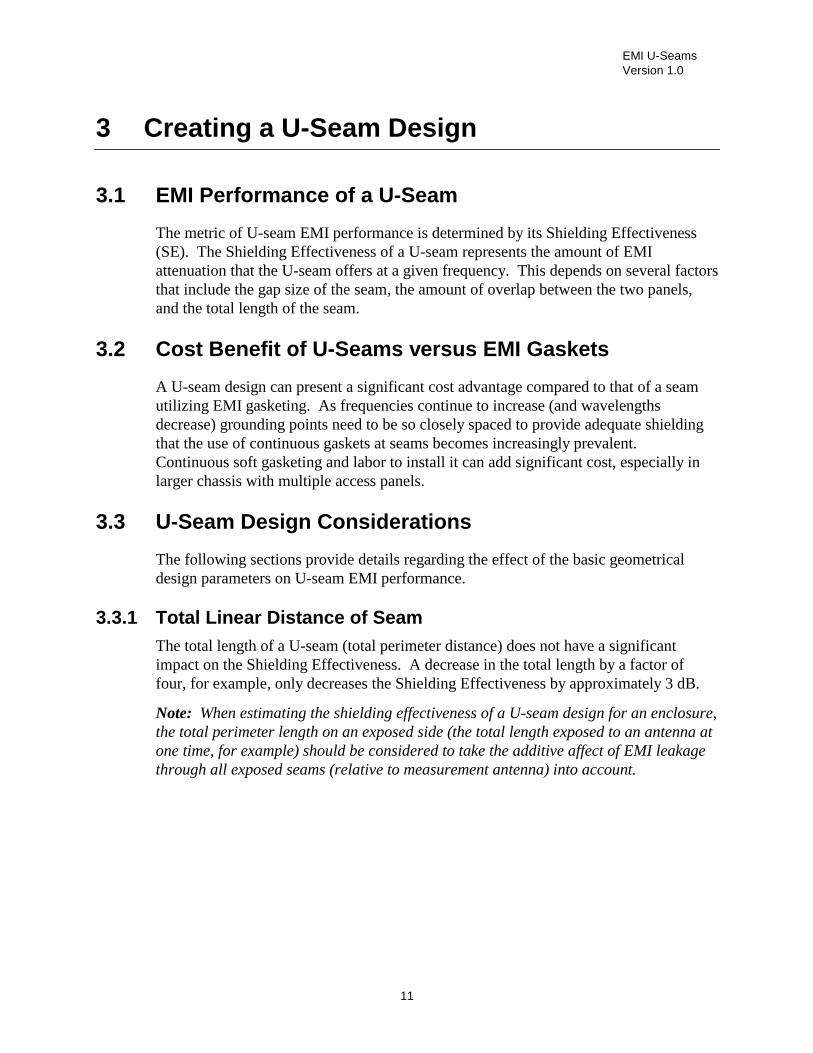
Figure 10 shows the measured effect of varying U-seam width on Shielding Effectiveness in the 1-4 GHz range.
Measured Effect of U-Seam Width on SE
0
5
10
15
20
25
30
35
40
45
1000 2000 3000 4000
Frequency (MHz)
Shi
eldi
ng E
ffec
tiven
ess
(dB
uV/m
)
1.56mm U-seam
1.76mm U-seam
1.96mm U-seam
2.76mm U-seam
3.26mm U-seam
Figure 10. Measured Effect of U-Seam Gap Size on SE
EMI U-Seams Version 1.0
16
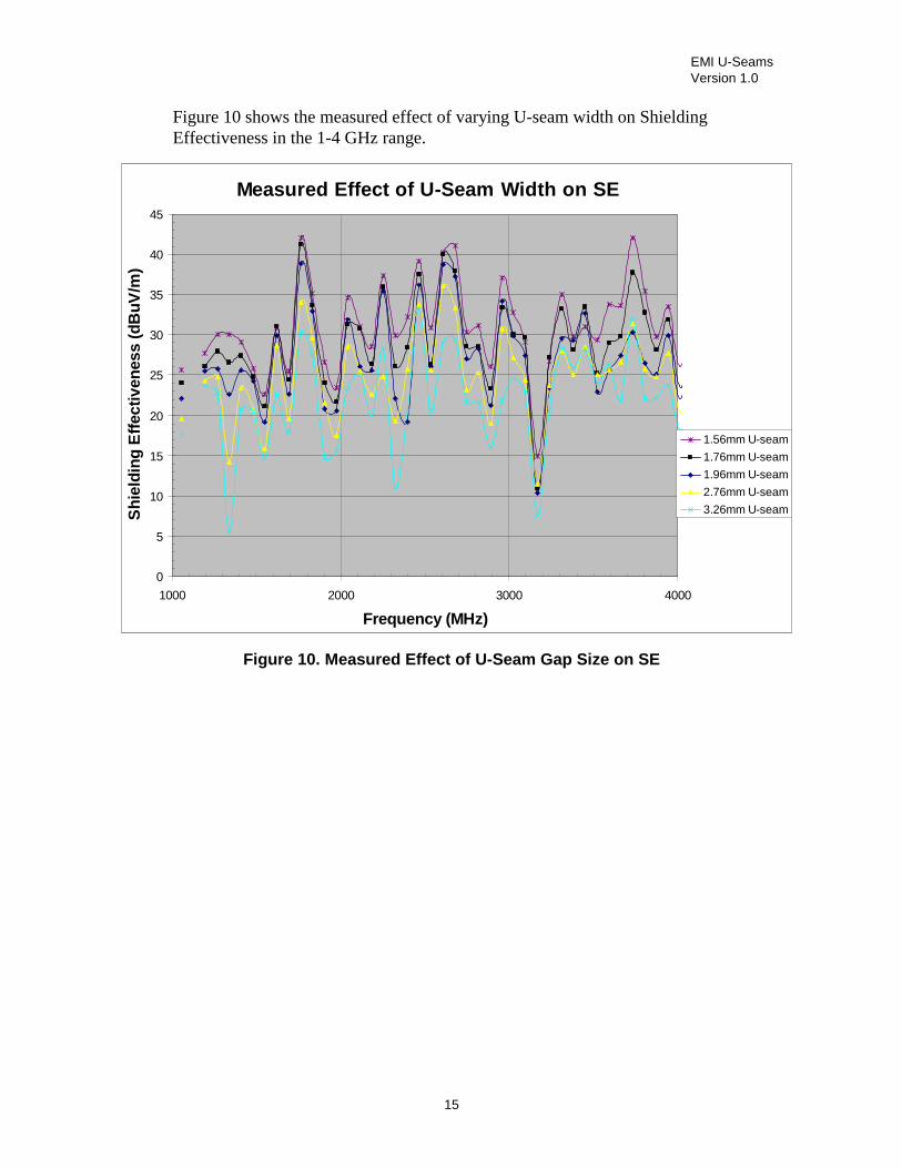
The plot in Figure 11 shows the predicted effect of changing the U-seam gap size and is based on empirical data.
Option 1 detail: U Width 1.5 mm; L Thickness 1 mm; Avg. Gap 0.25 mm; Overlap 7 mm; Total Seam Length 1000 mm
Option 2 detail: U Width 2.0 mm; L Thickness 1 mm; Avg. Gap 0.5 mm; Overlap 7 mm; Total Seam Length 1000 mm
Comparative Shielding Effectiveness Plot
0
5
10
15
20
25
30
35
40
1000 2000 3000 4000 5000 6000 7000 8000 9000 10000
Frequency (MHz)
Sh
ield
ing
Eff
ecti
ven
ess
(dB
uV
/m)
1.5mm U-Seam Width (0.25mm gap)
2.0mm U-Seam Width (0.50mm gap)
Figure 11. Predicted Effect of U-Seam Gap Size on SE

EMI U-Seams Version 1.0
17
3.3.3 Depth of Overlap Depth of overlap is the distance that the U-panel and L-panel overlap each other when assembled. An increase in depth of overlap increases the Shielding Effectiveness. An increase in the overlap from 6 mm to 7 mm, for example, increases the Shielding Effectiveness, but varies with frequency. At lower frequencies, overlap has more effect, but as frequencies increase, this effect diminishes.
Figure 12 shows the U-seam overlap geometry where the overlap variable is determined as the distance of overlap between the assembled L-panel and U-panel.
OverlapL-Panel
U-Panel
OverlapL-Panel
U-Panel
Figure 12. Overlap for Standard U-Seam Design
However, when a U-seam design includes a lead-in or chamfer, the overlap is calculated differently because the lead-in will reduce EMI performance of the U-seam. Figure 13 shows how Overlap is measured for a U-seam with a lead-in design. In this case, the distance is measured starting at approximately the center of the bent metal edge.
OverlapL-Panel
U-Panel Lead-in or Chamfer
Figure 13. Diminished Overlap because of Lead-In at U-seam Design
EMI U-Seams Version 1.0
18
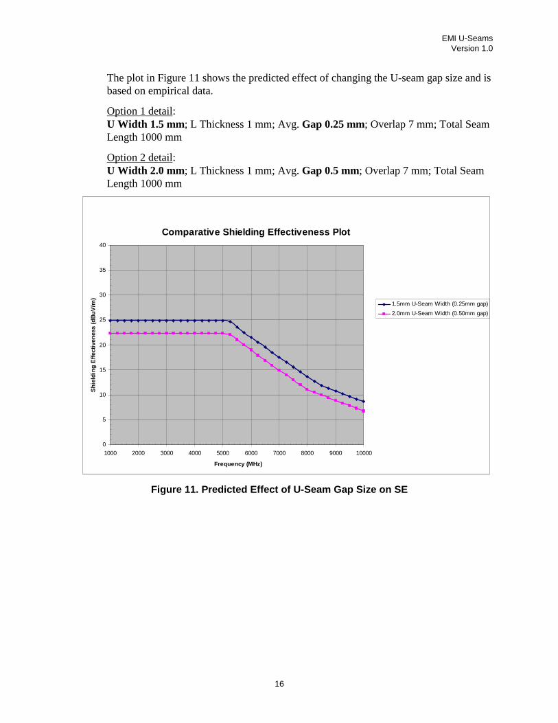
Figure 14 shows the measured effect of varying the depth of overlap on Shielding Effectiveness in the 1– 4 GHz range.
Measured Effect of U-Seam Depth of Overlap on SE
-20
-15
-10
-5
0
5
10
1000 2000 3000 4000
Frequency (MHz)
Impa
ct o
n S
E (d
BuV
/m)
5.2 mm overlap
4.4 mm overlap
3.6 mm overlap
2.8 mm overlap
2.0 mm overlap
1.2 mm overlap
0.4 mm overlap
Figure 14. Measured Effect of U-Seam Depth of Overlap on SE

EMI U-Seams Version 1.0
19
The plot in Figure 15 shows the predicted effect of changing the U-seam Depth of Overlap and is based on empirical data.
Option 1 detail: U Width 1.5 mm; L Thickness 1 mm; Avg. Gap 0.25 mm; Overlap 7 mm; Total Seam Length 1000 mm
Option 2 detail: U Width 1.5 mm; L Thickness 1 mm; Avg. Gap 0.25 mm; Overlap 6 mm; Total Seam Length 1000 mm
Comparative Shielding Effectiveness Plot
0
5
10
15
20
25
30
35
40
1000 2000 3000 4000 5000 6000 7000 8000 9000 10000
Frequency (MHz)
Sh
ield
ing
Eff
ecti
ven
ess
(dB
uV
/m)
7mm Overlap
6mm Overlap
Figure 15. Predicted Effect of U-Seam Depth of Overlap on SE
EMI U-Seams Version 1.0
20
3.4 Manufacturing Tolerance Considerations
When designing a U-seam for a particular application, it is important to design to worst-case tolerances that may exist in the chassis to ensure that a U-seam design is robust under all expected tolerance variations. While a quick CAD file review may show that a design is adequate, the actual formed sheet metal dimensions may prove to be very different and possibly inadequate. Although some guidelines will be provided in this section, it is important that a tolerance analysis be performed on your own U-seam design.
3.4.1 Evaluation of Worst Case U-Seam Configurations The following figures show two basic U-seam configurations. Depending upon the configuration used, different tolerances can be expected. The sections below will show typical tolerance expectations for each case and the corresponding maximum U-seam gap and minimum U-seam overlap. Each case is analyzed in the following sections.
EMI U-Seams Version 1.0
21
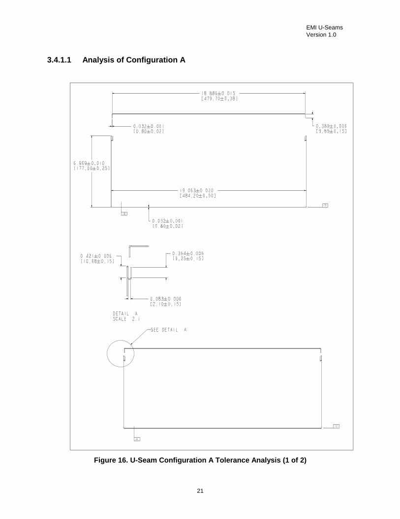
3.4.1.1 Analysis of Configuration A
Figure 16. U-Seam Configuration A Tolerance Analysis (1 of 2)

EMI U-Seams Version 1.0
22
Figure 17. U-Seam Configuration A Tolerance Analysis (2 of 2)

EMI U-Seams Version 1.0
23
Table 2. Tolerance Analysis of Configuration A
Component Nominal (in)Cover 18.8860 ± 0.0150Nominal Gap -0.0260 ± 0.0000U-Seam Width 0.0830 ± 0.0060Material Thickness 0.0320 ± 0.0010Chassis (Inside Wall to Inside Wall) -19.0630 ± 0.0200Material Thickness 0.0320 ± 0.0050U-Seam Width 0.0830 ± 0.0060TOLERANCE DIMENSION= 0.0270 RSS (3σ)=± 0.0269
Min Gap= 0.0001Max Gap= 0.0539
Min Width= 0.0770Max Width= 0.0890
Worst Case U-Seam Width (in) 0.0890Worst Case U-Seam Width (mm) 2.26
Component Nominal (in)I length (Cover) 0.3890 ± 0.0060Material Thickness 0.0320 ± 0.0010U-Seam Depth -0.4210 ± 0.0060Overlap Dimension 0.3640 ± 0.0060TOLERANCE DIMENSION= 0.3640 RSS (3σ)=± 0.0104
Min Dim= 0.3536Max Dim= 0.3744
Worst Case Overlap (in) 0.3536Worst Case Overlap (mm) 8.98
Tolerance (in)U-WIDTH AND GAP ANALYSIS
OVERLAP ANALYSIS
Tolerance (in)

EMI U-Seams Version 1.0
24
3.4.1.2 Analysis of Configuration B
Figure 18. U-Seam Configuration B Tolerance Analysis (1 or 2)

EMI U-Seams Version 1.0
25
Figure 19. U-Seam Configuration B Tolerance Analysis (2 or 2)

EMI U-Seams Version 1.0
26
Table 3. Tolerance Analysis of Configuration B
Component Nominal (in)Cover 18.1030 ± 0.0300Chassis (Right Hand "I" feature) 0.3930 ± 0.0060Chassis (Inside Wall to Inside Wall) -19.0200 ± 0.0200Chassis (Left Flat Wall) 0.4690 ± 0.0060U-Seam Width 0.0790 ± 0.0060TOLERANCE DIMENSION = 0.0240 RSS (3σ)=± 0.0375
Min Gap= 0.0000Max Gap= 0.0615Min Width= 0.0730Max Width=0.0850
Worst Case U-Seam Width (in) 0.0850Worst Case U-Seam Width (mm) 2.16
Horizontal Overlap 0.3620Minimum (Inches) 0.3245
Component Nominal (in)I length (Cover) 0.3920 ± 0.0060Material Thickness -0.0320 ± 0.0010U-Seam Depth -0.3610 ± 0.0060Overlap Dimension 0.3350 ± 0.0060TOLERANCE DIMENSION = 0.3340 RSS (3σ)=± 0.0104
Min Dim= 0.3236Max Dim= 0.3444
Worst Case Overlap (in) 0.3236Worst Case Overlap (mm) 8.22
Tolerance (in)
Tolerance (in)U-WIDTH AND GAP ANALYSIS
OVERLAP - HORIZONTAL ANALYSIS
OVERLAP - VERTICAL ANALYSIS
EMI U-Seams Version 1.0
27
3.5 General Design Considerations
• Avoid discontinuities in U-seams, such as breaks or interruptions as much as possible. These may result in resonance and leakage that adversely affect the overall Shielding Effectiveness.
• In most chassis designs, a U-seam needs to transition across a number of edges and corners. This can make it very difficult to create a continuous, unbroken U-seam when designing sheet metal components. It is therefore necessary to include gaps or breaks in the U-seam typically in corners where the U-seam transitions from one edge to another. These should be designed to minimize the break created. Based on containment requirement of 10 GHz, a maximum break of 1 cm would typically not degrade U-seam performance, but should be kept to 0.5 cm in the corner areas due to the higher concentration of currents.
• In a similar manner, the edge that fits into the U-seam may require breaks in the corners to accommodate manufacturing requirements. These should be designed to minimize the breaks created. Based on containment requirement of 10 GHz, a maximum break of 1 cm at the corner would typically not degrade U-seam performance.
• Some designs require breaks in a U-seam edge to accommodate a tab, mount bracket or clearance for a subassembly. These should be designed to minimize the breaks created. Based on containment requirement of 10 GHz, a maximum break of 1 cm would typically not degrade U-seam performance.
• Care should be taken when incorporating tabs or brackets in a U-seam. The tab or bracket can become a very efficient EMI radiator if its length approaches ¼, ½, or full wavelength of any frequencies radiating from the chassis enclosure.
• U-seams may need to have a lead-in or chamfer (refer to Figure 13) to assist alignment and assembly of the panel edge into the U-seam. Care should be taken not to compromise the Waveguide gap by incorporating a chamfer or angling one side of the U-seam to improve panel fit. Where used, a bent lead-in edge of a U-seam is not considered when calculating the overlap of a U-seam because this will diminish EMI performance.
• Avoid paint at the U-seam interface. Paint will reduce the shielding effectiveness and may cause assembly issues due to the added material thickness.
• When designing U-seams on large metal covers, ensure that the cover is rigid enough such that the U-seam will not partially disengage under normal conditions due to bowing.

EMI U-Seams Version 1.0
28
3.6 Cost/Performance Tradeoff
A deeper U-seam design may prove to be slightly more expensive (due to slightly more total material and possible tooling costs) than a more shallow design. However, the deeper design provides more Shielding Effectiveness and perhaps enables the chassis to contain higher frequencies for future applications. The deeper and narrower the U-seam design, however, the higher the potential for mechanical fit issues to occur because of mechanical tolerances. Avoiding mechanical issues because of EMI over-design is an important consideration in optimizing a U-seam design for overall quality and performance.

EMI U-Seams Version 1.0
29
4 Design Requirements
The following section describes the basic U-seam design requirements for a system. These requirements can be met with a number of design variations.
4.1 Compliance with EMC Requirements
EMC is regulated by different regulatory bodies in different geographies. For example, the Federal Communication Commission (FCC) regulates emissions for products sold in the United States. Products must comply with the EMC regulations in the geographic areas where the product will be marketed and sold. It is therefore imperative to ensure the system complies with the EMC regulations. Refer to your product regulations group for current information about regulations. Typically, Intel® products comply with the following EMC regulations:
• FCC, CFR 47, Part 15
• CISPR 22 / EN55022
• EN55024
4.2 Material Options
U-seams must be made of electrically conductive materials. Examples include zinc, nickel, steel, and aluminum. Compatible metals must be used in the enclosure; otherwise, galvanic corrosion may occur.
Materials of various conductivity have not been evaluated at this time. Predictive equations are based on data collected using zinc-plated sheet metal (electro-galvanized cold-rolled steel) test panels. It is expected that metals with similar or higher conductivity would result in similar performance; however, for materials that are considerably less conductive, Shielding Effectiveness is likely to decrease.


![a1w¨Ë> EMI c0 . ± c0 . Xv¾O^8Ð4< EMI Immunity …...ßP} ¿P ¨ ¿k=± EMI c0 . Ly5 U,]5 Xv¾O^8Ð4< 'a1w¨Ë> ([4>8nCMOS Xv¾O^8Ð4< ¨ ¿k=Ly5 U,]5 Xv¾O^8Ð4](https://img.dokumen.tips/doc/110x75/5faa729fabc0545fba225fc7/a1w-emi-c0-c0-xvo84-emi-immunity-p-p-k.jpg)