Embed Size (px)
Citation preview

Quick Start Guide
www.zyxel.com
EMG2926-Q10ADual-Band Wireless AC/N Gigabit Ethernet Gateway
Version 1.00Edition 2, 08/2015
Copyright © 2015 ZyXEL Communications Corporation
User’s Guide
Default Login DetailsLAN IP Address http://192.168.0.1
(Router Mode)User Name adminPassword (blank)

EMG2926-Q10A User’s Guide
2
IMPORTANT!
READ CAREFULLY BEFORE USE.
KEEP THIS GUIDE FOR FUTURE REFERENCE.
Screenshots and graphics in this book may differ slightly from your product due to differences in your product firmware or your computer operating system. Every effort has been made to ensure that the information in this manual is accurate.
Related Documentation
• Quick Start Guide
The Quick Start Guide shows how to connect the EMG2926-Q10A. It contains information on setting up your network and configuring for Internet access.

Contents Overview
EMG2926-Q10A User’s Guide
3
Contents Overview
User’s Guide .......................................................................................................................................10
Introduction ............................................................................................................................................. 11
Introducing the Web Configurator ...........................................................................................................18
Connection Wizard ..................................................................................................................................21
Easy Mode ..............................................................................................................................................31
Router Mode ...........................................................................................................................................42
Tutorials ..................................................................................................................................................50
Technical Reference ..........................................................................................................................62
Monitor ....................................................................................................................................................63
WAN ........................................................................................................................................................71
Wireless LAN ..........................................................................................................................................77
LAN .........................................................................................................................................................97
DHCP Server ........................................................................................................................................102
NAT .......................................................................................................................................................106
DDNS .................................................................................................................................................... 113
Static Route ........................................................................................................................................... 114
Firewall .................................................................................................................................................. 117
Content Filtering ....................................................................................................................................121
Parental Controls ..................................................................................................................................123
IPv6 Firewall ..........................................................................................................................................130
StreamBoost Management ...................................................................................................................133
Remote Management ............................................................................................................................139
Universal Plug-and-Play (UPnP) ...........................................................................................................145
USB Media Sharing ...............................................................................................................................147
Port Configuration .................................................................................................................................156
USB Print Server ...................................................................................................................................158
Mail ........................................................................................................................................................160
Maintenance ..........................................................................................................................................162
Troubleshooting ....................................................................................................................................172

Table of Contents
EMG2926-Q10A User’s Guide
4
Table of Contents
Contents Overview ..............................................................................................................................3
Table of Contents .................................................................................................................................4
Part I: User’s Guide ......................................................................................... 10
Chapter 1Introduction......................................................................................................................................... 11
1.1 Overview ........................................................................................................................................... 11
1.1.1 Dual-Band ................................................................................................................................12
1.2 Applications .......................................................................................................................................12
1.3 Ways to Manage the EMG2926-Q10A ..............................................................................................12
1.4 Good Habits for Managing the EMG2926-Q10A ...............................................................................13
1.5 Resetting the EMG2926-Q10A .........................................................................................................13
1.5.1 How to Use the RESET Button ................................................................................................13
1.6 The WPS Button ...............................................................................................................................13
1.7 LEDs .................................................................................................................................................14
1.8 Wall Mounting ...................................................................................................................................16
Chapter 2Introducing the Web Configurator ....................................................................................................18
2.1 Overview ...........................................................................................................................................18
2.2 Accessing the Web Configurator .......................................................................................................18
2.2.1 Login Screen ...........................................................................................................................18
2.2.2 Password Screen ....................................................................................................................19
Chapter 3Connection Wizard .............................................................................................................................21
3.1 Overview ...........................................................................................................................................21
3.2 Accessing the Wizard ........................................................................................................................21
3.3 Connect to Internet ............................................................................................................................22
3.3.1 Connection Type: IPoE ............................................................................................................23
3.3.2 Connection Type: PPPoE ........................................................................................................25
3.4 Router Password ...............................................................................................................................26
3.5 Wireless Security ..............................................................................................................................27
3.5.1 Wireless Security: No Security ................................................................................................27
3.5.2 Wireless Security: WPA2-PSK .................................................................................................28

Table of Contents
EMG2926-Q10A User’s Guide
5
Chapter 4Easy Mode ...........................................................................................................................................31
4.1 Overview ...........................................................................................................................................31
4.2 Navigation Panel ...............................................................................................................................32
4.3 Network Map .....................................................................................................................................33
4.4 Control Panel ....................................................................................................................................33
4.4.1 Power Saving ..........................................................................................................................34
4.4.2 Parental Controls .....................................................................................................................35
4.4.3 Firewall ....................................................................................................................................36
4.4.4 Internet Settings ......................................................................................................................37
4.4.5 Wireless Security .....................................................................................................................39
4.4.6 WPS ........................................................................................................................................40
4.5 Status Screen in Easy Mode .............................................................................................................40
Chapter 5Router Mode........................................................................................................................................42
5.1 Overview ...........................................................................................................................................42
5.2 Router Mode Status Screen ..............................................................................................................42
5.2.1 Navigation Panel .....................................................................................................................45
Chapter 6Tutorials...............................................................................................................................................50
6.1 Overview ...........................................................................................................................................50
6.2 Set Up a Wireless Network with WPS ...............................................................................................50
6.2.1 Push Button Configuration (PBC) ............................................................................................50
6.2.2 PIN Configuration ....................................................................................................................51
6.3 Configure Wireless Security without WPS ........................................................................................52
6.3.1 Configure Your Notebook ........................................................................................................54
6.4 Using Multiple SSIDs on the EMG2926-Q10A ..................................................................................56
6.4.1 Configuring Security Settings for Multiple SSIDs ....................................................................57
Part II: Technical Reference............................................................................ 62
Chapter 7Monitor.................................................................................................................................................63
7.1 Overview ...........................................................................................................................................63
7.2 The Log Screen .................................................................................................................................63
7.2.1 View Log ..................................................................................................................................63
7.2.2 Log Setting ..............................................................................................................................64
7.3 DHCP Table ...................................................................................................................................64
7.4 IPv6 Neighbor Table ..........................................................................................................................65

Table of Contents
EMG2926-Q10A User’s Guide
6
7.5 Packet Statistics .............................................................................................................................66
7.6 WLAN Station Status .....................................................................................................................67
7.7 Internet Sessions ..............................................................................................................................68
7.8 DLNA Clients .....................................................................................................................................70
Chapter 8WAN .....................................................................................................................................................71
8.1 Overview ...........................................................................................................................................71
8.2 Internet Connection ...........................................................................................................................72
8.3 Advanced WAN Screen ....................................................................................................................75
Chapter 9Wireless LAN.......................................................................................................................................77
9.1 Overview ...........................................................................................................................................77
9.2 General Wireless LAN Screen .........................................................................................................78
9.3 Wireless Security ..............................................................................................................................80
9.3.1 No Security ..............................................................................................................................80
9.3.2 WEP Encryption ......................................................................................................................81
9.3.3 WPA-PSK/WPA2-PSK .............................................................................................................82
9.3.4 WPA/WPA2 ..............................................................................................................................83
9.4 More AP Screen ................................................................................................................................85
9.4.1 More AP Edit ...........................................................................................................................86
9.5 MAC Filter Screen ............................................................................................................................88
9.6 Wireless LAN Advanced Screen .......................................................................................................89
9.7 Quality of Service (QoS) Screen .......................................................................................................90
9.8 WPS Screen ......................................................................................................................................91
9.9 WPS Station Screen ..........................................................................................................................92
9.10 Scheduling Screen ..........................................................................................................................93
9.11 WDS Screen ....................................................................................................................................94
9.12 Channel Status Screen ...................................................................................................................95
Chapter 10LAN ......................................................................................................................................................97
10.1 Overview .........................................................................................................................................97
10.2 LAN IP Screen ................................................................................................................................97
10.3 IP Alias Screen ................................................................................................................................98
10.4 IPv6 LAN Screen .............................................................................................................................99
10.5 LAN Advanced Screen ..................................................................................................................100
Chapter 11DHCP Server .....................................................................................................................................102
11.1 Overview .......................................................................................................................................102
11.2 DHCP Server General Screen ......................................................................................................102

Table of Contents
EMG2926-Q10A User’s Guide
7
11.3 DHCP Server Advanced Screen ................................................................................................103
11.4 DHCP Client List Screen ...............................................................................................................104
Chapter 12NAT.....................................................................................................................................................106
12.1 Overview ....................................................................................................................................106
12.2 NAT General Screen .....................................................................................................................107
12.3 Port Forwarding Screen ...............................................................................................................107
12.3.1 Port Forwarding Edit Screen ..............................................................................................109
12.4 Port Trigger Screen ....................................................................................................................... 111
Chapter 13DDNS.................................................................................................................................................. 113
13.1 Overview ...................................................................................................................................... 113
13.2 General ....................................................................................................................................... 113
Chapter 14Static Route ....................................................................................................................................... 114
14.1 Overview .................................................................................................................................... 114
14.2 IP Static Route Screen ................................................................................................................. 114
14.2.1 Add/Edit Static Route .......................................................................................................... 115
Chapter 15Firewall .............................................................................................................................................. 117
15.1 Overview ..................................................................................................................................... 117
15.2 General Screen ............................................................................................................................ 117
15.3 Services Screen ............................................................................................................................ 118
Chapter 16Content Filtering ...............................................................................................................................121
16.1 Overview .......................................................................................................................................121
16.2 Content Filter Screen ....................................................................................................................121
Chapter 17Parental Controls ..............................................................................................................................123
17.1 Overview .......................................................................................................................................123
17.2 Parental Control Screen ................................................................................................................123
17.2.1 Add/Edit a Parental Control Rule .........................................................................................124
17.2.2 Add/Edit a Service ...............................................................................................................126
17.3 Parental Monitor Screen ...............................................................................................................127
17.3.1 Add/Edit a Parental Monitor Rule ........................................................................................128
Chapter 18IPv6 Firewall ......................................................................................................................................130

Table of Contents
EMG2926-Q10A User’s Guide
8
18.1 Overview .......................................................................................................................................130
18.2 IPv6 Firewall Screen ....................................................................................................................130
Chapter 19StreamBoost Management...............................................................................................................133
19.1 Overview ......................................................................................................................................133
19.2 Network Screen ............................................................................................................................134
19.3 Up Time Screen ...........................................................................................................................134
19.4 Downloads Screen .......................................................................................................................135
19.5 PerDevice Screen .........................................................................................................................136
19.6 PerFlow Screen .............................................................................................................................138
Chapter 20Remote Management........................................................................................................................139
20.1 Overview .......................................................................................................................................139
20.2 WWW Screen .............................................................................................................................139
20.3 SNMP ............................................................................................................................................140
20.4 Wake On LAN Screen ...................................................................................................................143
Chapter 21Universal Plug-and-Play (UPnP)......................................................................................................145
21.1 Overview ......................................................................................................................................145
21.2 UPnP Screen ...............................................................................................................................145
Chapter 22USB Media Sharing...........................................................................................................................147
22.1 Overview .......................................................................................................................................147
22.2 DLNA Screen ................................................................................................................................148
22.3 SAMBA Screen .............................................................................................................................149
22.4 FTP Screen ...................................................................................................................................151
22.5 How to Access Your Shared Files From a Computer ....................................................................152
22.5.1 Use Windows Explorer to Share Files .................................................................................152
22.5.2 Use FTP to Share Files .......................................................................................................154
Chapter 23Port Configuration ............................................................................................................................156
23.1 Overview .......................................................................................................................................156
23.2 Port Configuration Screen .............................................................................................................156
Chapter 24USB Print Server...............................................................................................................................158
24.1 Overview .......................................................................................................................................158
24.2 Print Server Screen .......................................................................................................................158

Table of Contents
EMG2926-Q10A User’s Guide
9
Chapter 25Mail.....................................................................................................................................................160
25.1 Overview .......................................................................................................................................160
25.2 My Mail Screen .............................................................................................................................160
Chapter 26Maintenance ......................................................................................................................................162
26.1 Overview .......................................................................................................................................162
26.2 General Screen .............................................................................................................................162
26.3 Account Screen .............................................................................................................................162
26.3.1 Edit a User’s Account ..........................................................................................................163
26.4 Configuration Backup/Restore Screen ..........................................................................................164
26.5 Restart Screen ..............................................................................................................................165
26.6 System Operating Mode Overview ...............................................................................................166
26.7 Sys OP Mode Screen ....................................................................................................................167
26.8 Language Screen ..........................................................................................................................168
26.9 Diagnostic Screen .........................................................................................................................168
26.9.1 Ping Screen .........................................................................................................................168
26.9.2 TraceRoute Screen ..............................................................................................................169
26.9.3 Nslookup Screen .................................................................................................................170
26.9.4 SpeedTest Screen ...............................................................................................................170
Chapter 27Troubleshooting................................................................................................................................172
27.1 Overview .......................................................................................................................................172
27.2 Power, Hardware Connections, and LEDs ....................................................................................172
27.3 EMG2926-Q10A Access and Login ..............................................................................................173
27.4 Internet Access .............................................................................................................................174
27.5 Resetting the EMG2926-Q10A to Its Factory Defaults .................................................................176
27.6 Wireless Connections ...................................................................................................................176
27.7 USB Device Problems ...................................................................................................................178

10
PART IUser’s Guide

EMG2926-Q10A User’s Guide
11
CHAPTER 1
Introduction
1.1 Overview
This chapter introduces the main features and applications of the EMG2926-Q10A.
The EMG2926-Q10A extends the range of your existing wired network without additional wiring, providing easy network access to mobile users. You can set up a wireless network with other IEEE 802.11a/ac/b/g/n compatible devices.
A range of services such as a firewall and content filtering are also available for secure Internet computing. The EMG2926-Q10A also supports the new StreamBoost Smart Quality of Service (QoS) technology, which redistributes traffic over the EMG2926-Q10A for the best possible performance in a home network.
There are two USB 2.0 ports on the side panel of your EMG2926-Q10A. You can connect USB memory sticks (version 2.0 or lower), USB hard drives, or USB devices for file sharing. The EMG2926-Q10A automatically detects USB devices.
Two USB eject buttons are located above the USB ports. Hold down the eject button for the corresponding USB port for 2 seconds. Make sure the USB LED is off before removing your USB device. This will remove your USB device safely, preventing the loss of files or data being transmitted through the USB device.
Figure 1 USB Ports and Eject Buttons
Note: For the USB function, it is strongly recommended to use version 2.0 or lower USB storage devices (memory sticks, USB hard drives, etc.) and/or USB devices. Other USB products are not guaranteed to function properly with the EMG2926-Q10A.
Eject buttons
USB portsOR
Eject buttons
USB ports

Chapter 1 Introduction
EMG2926-Q10A User’s Guide
12
1.1.1 Dual-Band
The EMG2926-Q10A is a dual-band AP and is able to operate both 2.4G and 5G networks at the same time. You could use the 2.4 GHz band for regular Internet surfing and downloading while using the 5 GHz band for time-sensitive traffic like high-definition video, music, and gaming.
Figure 2 Dual-Band Application
1.2 Applications
You can have the following networks with the EMG2926-Q10A:
• Wired. You can connect network devices via the Ethernet ports of the EMG2926-Q10A so that they can communicate with each other and access the Internet.
• Wireless. Wireless clients can connect to the EMG2926-Q10A to access network resources. You can use WPS (Wi-Fi Protected Setup) to create an instant network connection with another WPS-compatible device.
• WAN. Connect to a broadband modem/router for Internet access.
1.3 Ways to Manage the EMG2926-Q10A
Use any of the following methods to manage the EMG2926-Q10A.
• WPS (Wi-Fi Protected Setup). You can use the WPS button or the WPS section of the Web Configurator to set up a wireless network with your EMG2926-Q10A.
• Web Configurator. This is recommended for everyday management of the EMG2926-Q10A using a (supported) web browser.
Chapter 1 Introduction
EMG2926-Q10A User’s Guide
13
1.4 Good Habits for Managing the EMG2926-Q10A
Do the following things regularly to make the EMG2926-Q10A more secure and to manage the EMG2926-Q10A more effectively.
• Change the password. Use a password that’s not easy to guess and that consists of different types of characters, such as numbers and letters.
• Write down the password and put it in a safe place.
• Back up the configuration (and make sure you know how to restore it). Restoring an earlier working configuration may be useful if the device becomes unstable or even crashes. If you forget your password, you will have to reset the EMG2926-Q10A to its factory default settings. If you backed up an earlier configuration file, you would not have to totally re-configure the EMG2926-Q10A. You could simply restore your last configuration.
1.5 Resetting the EMG2926-Q10A
If you forget your password or IP address, or if you cannot access the Web Configurator, you will need to use the RESET button at the back of the EMG2926-Q10A to reload the factory-default configuration file. This means that you will lose all configurations that you had previously saved. The user name will be reset to “admin” and the IP address will be reset to “192.168.0.1”. The default password is an empty string.
1.5.1 How to Use the RESET Button
1 Make sure the power LED is on.
2 Press the RESET button for one to four seconds to restart/reboot the EMG2926-Q10A.
3 Hold down the RESET button for longer than five seconds to reset the EMG2926-Q10A to its factory-default configuration.
1.6 The WPS Button
Your EMG2926-Q10A supports Wi-Fi Protected Setup (WPS), which is an easy way to set up a secure wireless network. WPS is an industry-standard specification, defined by the Wi-Fi Alliance.
WPS allows you to quickly set up a wireless network with strong security, without having to configure security settings manually. Each WPS connection works between two devices. Both devices must support WPS (check each device’s documentation to make sure).
Depending on the devices you have, you can either press a button (on the device itself, or in its configuration utility) or enter a PIN (a unique Personal Identification Number that allows one device to authenticate the other) on each of the two devices. When WPS is activated on a device, it has two minutes to find another device that also has WPS activated. Then, the two devices connect and set up a secure network by themselves.

Chapter 1 Introduction
EMG2926-Q10A User’s Guide
14
You can use the WPS button ( or ) on the front panel of the EMG2926-Q10A to activate WPS in order to quickly set up a wireless network with strong security.
1 Make sure the power LED is on (not blinking).
2 Press the WPS button for more than three seconds and release it. Press the WPS button on another WPS-enabled device within range of the EMG2926-Q10A.
Note: You must activate WPS on the EMG2926-Q10A and on another wireless device within two minutes of each other.
For more information on using WPS, see Section 6.2 on page 50.
1.7 LEDs
Look at the LED lights on the front panel to determine the status of the EMG2926-Q10A. Use the LED button at the side panel of the device to turn the LED lights on or off. If the LED button is already in the ON position but none of the LEDS are on, make sure the EMG2926-Q10A is receiving power and the power is turned on.
Note: The Power LED will be on even if you push the LED button to the OFF position. This is for you to determine whether the EMG2926-Q10A is powered on.
Figure 3 LED Button
LED button LED button
OR

Chapter 1 Introduction
EMG2926-Q10A User’s Guide
15
Figure 4 Front Panel
The following table describes the LEDs and the WPS button.
Table 1 Front Panel LEDs and WPS ButtonLED STATUS DESCRIPTION
WPS Button Press this button for 1 second to set up a wireless connection via WiFi Protected Setup with another WPS-enabled client. You must press the WPS button on the client side within 120 seconds for a successful connection. See Section 1.6 on page 13 and Section 6.2 on page 50 for more information on WPS.
Power On The EMG2926-Q10A is receiving power and functioning properly.
Off The EMG2926-Q10A is not receiving power.
WAN On The EMG2926-Q10A’s WAN connection is ready.
Blinking The EMG2926-Q10A is sending/receiving data through the WAN at a 1000Mbps transmission rate.
Off The WAN connection is not ready, or has failed.
Internet On The EMG2926-Q10A has an IP connection but no traffic.
Your device has a WAN IP address (either static or assigned by a DHCP server), PPP negotiation was successfully completed (if used) and the connection is up.
Blinking The EMG2926-Q10A is sending or receiving IP traffic.
Off The EMG2926-Q10A does not have an IP connection.
Power
LAN 1-4
WAN
WPS
USB 1-2WPS Button
Internet
WLAN 5G
WLAN 2.4G
OR
Power
LAN 1-4
WAN
WPS
USB 1-2
Internet
WLAN 5G
WLAN 2.4G

Chapter 1 Introduction
EMG2926-Q10A User’s Guide
16
1.8 Wall Mounting
You may need screw anchors if mounting on a concrete or brick wall.
1 Select a position free of obstructions on a wall strong enough to hold the weight of the device.
2 Mark two holes on the wall at the appropriate distance apart for the screws.
Be careful to avoid damaging pipes or cables located inside the wall when drilling holes for the screws.
3 If using screw anchors, drill two holes for the screw anchors into the wall. Push the anchors into the full depth of the holes, then insert the screws into the anchors. Do not insert the screws all the way in - leave a gap of about 0.5 cm.
If not using screw anchors, use a screwdriver to insert the screws into the wall. Do not insert the screws all the way in - leave a gap of about 0.5 cm.
4 Make sure the screws are fastened well enough to hold the weight of the EMG2926-Q10A with the connection cables.
5 Align the holes on the back of the EMG2926-Q10A with the screws on the wall. Hang the EMG2926-Q10A on the screws.
WLAN 2.4/5G On The EMG2926-Q10A is ready, but is not sending/receiving data through the 5G wireless LAN.
Blinking The EMG2926-Q10A is sending/receiving data through the 5G wireless LAN.
The EMG2926-Q10A is negotiating a WPS connection with a wireless client.
Off The wireless LAN is not ready or has failed.
LAN 1-4 On The EMG2926-Q10A’s LAN connection is ready.
Blinking The EMG2926-Q10A is sending/receiving data through the LAN at a 1000Mbps transmission rate.
Off The LAN connection is not ready, or has failed.
USB 1-2 On The EMG2926-Q10A has a USB device installed.
Blinking The EMG2926-Q10A is transmitting and/or receiving data from routers through an installed USB device.
Off There is no USB device connected to the EMG2926-Q10A.
Table 1 Front Panel LEDs and WPS Button (continued)LED STATUS DESCRIPTION
Table 2 Wall Mounting InformationDistance between holes 12.7 cm
M4 screws Two
Screw anchors (optional) Two

Chapter 1 Introduction
EMG2926-Q10A User’s Guide
17
Figure 5 Wall Mounting Example

EMG2926-Q10A User’s Guide
18
CHAPTER 2
Introducing the Web Configurator
2.1 Overview
This chapter describes how to access the EMG2926-Q10A Web Configurator and provides an overview of its screens.
The Web Configurator is an HTML-based management interface that allows for easy setup and management of the EMG2926-Q10A via an Internet browser. Use Internet Explorer 9.0 and later versions, Mozilla Firefox 21 and later versions, Safari 6.0 and later versions or Google Chrome 26.0 and later versions. The recommended screen resolution is 1024 by 768 pixels.
In order to use the Web Configurator you need to allow:
• web browser pop-up windows on your device. Web pop-up blocking is enabled by default in Windows XP SP (Service Pack) 2;
• JavaScript (enabled by default);
• Java permissions (enabled by default).
2.2 Accessing the Web Configurator
1 Make sure your EMG2926-Q10A hardware is properly connected and prepare your computer or computer network to connect to the EMG2926-Q10A (refer to the Quick Start Guide).
2 Launch your web browser.
3 The EMG2926-Q10A is in router mode by default. Type "http://192.168.0.1" as the website address.
If the EMG2926-Q10A is in access point mode, the IP address is 192.168.0.2.
Your computer must be in the same subnet in order to access this website address.
2.2.1 Login Screen
The Web Configurator initially displays the login screen below.

Chapter 2 Introducing the Web Configurator
EMG2926-Q10A User’s Guide
19
Figure 6 Login Screen
The following table describes the labels on this screen.
2.2.2 Password Screen
You should see a screen asking you to change your password (highly recommended), as shown below.
Figure 7 Change Password Screen
Table 3 Login ScreenLABEL DESCRIPTION
Language Select the language you want to use to configure the Web Configurator.
User Type "admin" (default) as the user name. Click Login.
Password Leave this field blank.

Chapter 2 Introducing the Web Configurator
EMG2926-Q10A User’s Guide
20
The following table describes the labels on this screen.
Note: The management session automatically times out when the time period set in the Administrator Inactivity Timer field expires (default five minutes; go to Chapter 26 on page 162 to change). If this happens, simply log back in to the EMG2926-Q10A.
Table 4 Change Password ScreenLABEL DESCRIPTION
New Password Type a new password.
Retype to Confirm Retype the password for confirmation.
Apply Click Apply to save your changes with the EMG2926-Q10A.
Ignore Click Ignore if you do not want to change the password this time.

EMG2926-Q10A User’s Guide
21
CHAPTER 3
Connection Wizard
3.1 Overview
This chapter provides information on the wizard setup screens in the Web Configurator.
The Web Configurator’s setup wizard helps you configure your device to access the Internet. Refer to your ISP for your Internet account information. Leave a field blank if you don’t have that information.
3.2 Accessing the Wizard
Launch your web browser and type "http://192.168.0.1" as the website address. Type "admin" (default) as the user name and leave the password field blank. Click Login.
Note: The Web Configurator is set to Easy Mode by default after login. If you are in Expert Mode, you can click the Easy Mode icon on the upper right corner of any Web Configurator screen to go to Easy Mode.
Click the eaZy123 icon on the network map screen in Easy Mode. The Wizard screen will open. Choose your Language and click Connect to Internet.
Figure 8 Welcome

Chapter 3 Connection Wizard
EMG2926-Q10A User’s Guide
22
3.3 Connect to Internet
The EMG2926-Q10A allows you to choose between two Internet connection types: IPoE or PPPoE. The wizard attempts to detect which WAN connection type you are using.
Figure 9 Detecting your Internet Connection Type
If the wizard does not detect a connection type, you must select one from the drop-down list box. Check with your ISP to make sure you use the correct type.
Note: If you get an error message, check your hardware connections. Make sure your Internet connection is up and running.
The following screen depends on your Internet connection type. Enter the details provided by your Internet Service Provider (ISP) in the fields (if any).

Chapter 3 Connection Wizard
EMG2926-Q10A User’s Guide
23
Figure 10 Internet Connection Type
Your EMG2926-Q10A detects the following Internet Connection types.
3.3.1 Connection Type: IPoE
Choose IPoE as the Internet Connection Type when the WAN port is used as a regular Ethernet. Click Next.
Table 5 Internet Connection TypesCONNECTION TYPE DESCRIPTION
IPoE Select the IPoE (IP over Ethernet) option when the WAN port is used as a regular Ethernet.
PPPoE Select the PPPoE (Point-to-Point Protocol over Ethernet) option for a dial-up connection.

Chapter 3 Connection Wizard
EMG2926-Q10A User’s Guide
24
Figure 11 Internet Connection Type: IPoE
The following table describes the labels on this screen.
Note: If you get an error screen after clicking Next, you might have selected the wrong Internet Connection type. Click Back, make sure your Internet connection is working and select the right Connection Type. Contact your ISP if you are not sure of your Internet Connection Type.
Table 6 Internet Connection Type: IPoELABEL DESCRIPTION
Internet Connection Type Select the IPoE option.
Obtain an IP Address Automatically
Select this radio button if your Internet Service Provider (ISP) did not assign you a fixed IP address.
Static IP Address Select this radio button if your ISP assigned an IP address for your Internet connection.
IP Address Enter the IP address provided by your ISP.
Subnet Mask Enter the IP subnet mask in this field.
Gateway IP Address Enter the gateway IP address in this field.
First DNS Server
Second DNS Server
Select Obtained From ISP if your ISP dynamically assigns DNS server information (and the EMG2926-Q10A's WAN IP address). The field to the right displays the (read-only) DNS server IP address that the ISP has assigned.
Select User-Defined if you have the IP address of a DNS server. Enter the DNS server's IP address in the field to the right.
Select None if you do not want to configure DNS servers. If you do not configure a DNS server, you must know the IP address of a computer in order to access it.
Exit Click this button to close the wizard screen without saving.
Back Click this button to return to the previous screen.
Next Click this button to continue.

Chapter 3 Connection Wizard
EMG2926-Q10A User’s Guide
25
3.3.2 Connection Type: PPPoE
Point-to-Point Protocol over Ethernet (PPPoE) functions as a dial-up connection. PPPoE is an IETF (Internet Engineering Task Force) standard specifying how a host personal computer interacts with a broadband modem (DSL, cable, wireless, etc.) to achieve access to high-speed data networks.
For the service provider, PPPoE offers an access and authentication method that works with existing access control systems (RADIUS, etc.).
One of the benefits of PPPoE is the ability to let end users access one of multiple network services, a function known as dynamic service selection. This enables the service provider to easily create and offer new IP services for specific users.
Operationally, PPPoE saves significant effort for both the subscriber and the ISP/carrier, as it requires no specific configuration of the broadband modem at the subscriber's site.
By implementing PPPoE directly on the EMG2926-Q10A (rather than individual computers), the computers on the LAN do not need PPPoE software installed, as the EMG2926-Q10A does that part of the task. Furthermore, with NAT, all of the LAN's computers will have Internet access.
Figure 12 Internet Connection Type: PPPoE
The following table describes the labels on this screen.
Table 7 Internet Connection Type: PPPoELABEL DESCRIPTION
Internet Connection Type
Select the PPPoE option for a dial-up connection.
Get automatically from ISP
Select this radio button if your ISP did not assign you a fixed IP address.
Use Fixed IP Address
Select this radio button to give the EMG2926-Q10A a fixed, unique IP address.
PPP Username Type the user name given to you by your ISP.

Chapter 3 Connection Wizard
EMG2926-Q10A User’s Guide
26
The EMG2926-Q10A connects to the Internet.
Figure 13 Connecting to the Internet
Note: If the Wizard successfully connects to the Internet, it proceeds to the next step. If you get an error message, go back to the previous screen and make sure you have entered the correct information provided by your ISP.
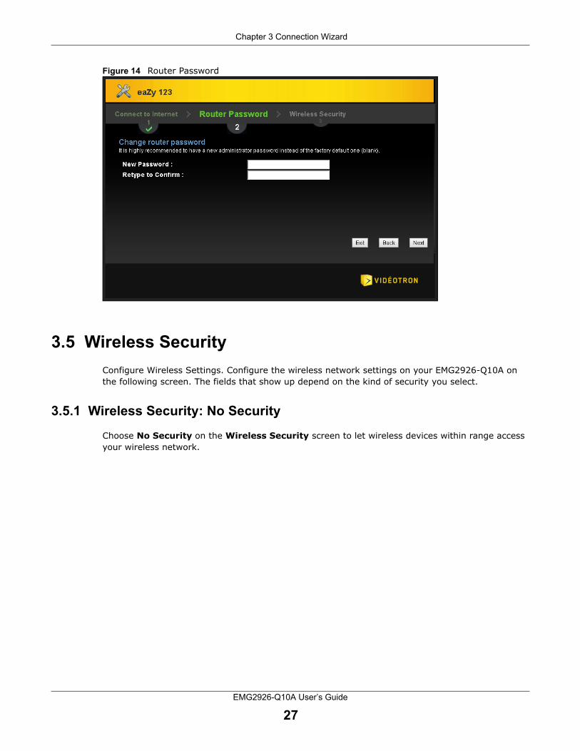
3.4 Router Password
Change the login password in the following screen. Enter the new password and retype it to confirm. Click Next to proceed with the Wireless Security screen.
PPP Password Type the password associated with the user name above.
My WAN IP Address Type the name of your service provider.
Exit Click this to close the wizard screen without saving.
Back Click this to return to the previous screen.
Next Click this to continue.
Table 7 Internet Connection Type: PPPoE (continued)LABEL DESCRIPTION
Chapter 3 Connection Wizard
EMG2926-Q10A User’s Guide
27
Figure 14 Router Password
3.5 Wireless Security
Configure Wireless Settings. Configure the wireless network settings on your EMG2926-Q10A on the following screen. The fields that show up depend on the kind of security you select.
3.5.1 Wireless Security: No Security
Choose No Security on the Wireless Security screen to let wireless devices within range access your wireless network.

Chapter 3 Connection Wizard
EMG2926-Q10A User’s Guide
28
Figure 15 Wireless Security: No Security
The following table describes the labels on this screen.
3.5.2 Wireless Security: WPA2-PSK
Choose WPA2-PSK security in the Wireless Security screen to set up a password for your wireless network.
Table 8 Wireless Security: No SecurityLABEL DESCRIPTION
Wireless Network Name (SSID)
Enter a descriptive name (up to 32 printable 7-bit ASCII characters) for the wireless LAN.
If you change this field on the EMG2926-Q10A, make sure all wireless stations use the same SSID in order to access the network.
Security Mode Select a security level from the drop-down list box.
Choose No Security to have no wireless LAN security configured. If you do not enable any wireless security on your EMG2926-Q10A, your network is accessible to any wireless networking device that is within range.
Exit Click this to close the wizard screen without saving.
Back Click this to return to the previous screen.
Next Click this to continue.

Chapter 3 Connection Wizard
EMG2926-Q10A User’s Guide
29
Figure 16 Wireless Security: WPA2-PSK
The following table describes the labels on this screen.
Congratulations! Open a web browser, such as Internet Explorer, to visit your favourite website.
Note: If you cannot access the Internet when your computer is connected to one of the EMG2926-Q10A’s LAN ports, check your connections. Then, turn the EMG2926-Q10A off, wait for a few seconds, and turn it back on. If that does not work, log in to the web configurator again and check if you have typed all information correctly. See the User’s Guide for more suggestions.
Table 9 Wireless Security: WPA2-PSKLABEL DESCRIPTION
Wireless Network Name (SSID)
Enter a descriptive name (up to 32 printable 7-bit ASCII characters) for the wireless LAN.
If you change this field on the EMG2926-Q10A, make sure all wireless stations use the same SSID in order to access the network.
Security Mode Select a security level from the drop-down list box.
Choose WPA2-PSK security to configure a Pre-Shared Key. Choose this option only if your wireless clients support WPA2-PSK.
Wireless password
Type between 8 to 63 case-sensitive ASCII characters. Set up the most secure wireless connection possible by configuring WPA in the wireless LAN screens.
Verify Password Retype the password to confirm.
Exit Click this to close the wizard screen without saving.
Back Click this to return to the previous screen.
Next Click this to continue.

Chapter 3 Connection Wizard
EMG2926-Q10A User’s Guide
30
Figure 17 Congratulations
You can also click GO to open the Easy Mode Web Configurator of your EMG2926-Q10A.
You have successfully set up your EMG2926-Q10A to operate on your network and access the Internet. You are now ready to connect wirelessly to your EMG2926-Q10A and access the Internet.

EMG2926-Q10A User’s Guide
31
CHAPTER 4
Easy Mode
4.1 Overview
The Web Configurator is set to Easy Mode by default. You can configure several key features of the EMG2926-Q10A in this mode. This mode is useful for users who are not fully familiar with some features that are usually intended for network administrators.
The following screen will appear when you log in to the Web Configurator.
Figure 18 Easy Mode: Network Map
Click Status to open the following screen.
Network Map
Control Panel
Go toStatusScreen
Navigation Panel

Chapter 4 Easy Mode
EMG2926-Q10A User’s Guide
32
Figure 19 Easy Mode: Status Screen
4.2 Navigation Panel
Use this navigation panel to opt out of the Easy Mode.
Figure 20 Control Panel
The following table describes the labels on this screen.
Control Panel
Status Screen
Go toNetworkMapScreen
Navigation Panel
Table 10 Control PanelITEM DESCRIPTION
Expert Mode Click this to change to Expert Mode and customize features of the EMG2926-Q10A.
eaZy123 Click this icon to open the setup wizard.
Logout Click this to end the Web Configurator session and go to the Login page.

Chapter 4 Easy Mode
EMG2926-Q10A User’s Guide
33
4.3 Network Map
When you log into the Web Configurator, the Network Map is shown as follows.
Figure 21 Network Map
You can view the upstream and downstream transmission speeds between the EMG2926-Q10A and the Internet and/or between the EMG2926-Q10A and the connected device(s) (represented by icons indicating the kind of network device), including those which connect wirelessly. Hover your cursor over a device icon to view details about the device, such as the name, IP address, MAC address, device type and connection type.
4.4 Control Panel
The features that are configurable in Easy Mode are shown in the Control Panel.
Figure 22 Control Panel
Switch ON to enable the feature. Otherwise, switch OFF. If the feature is turned on, the green light will flash. If it is turned off, the red light will flash.
You can also click on the feature to open a screen where you can edit its settings.
Chapter 4 Easy Mode
EMG2926-Q10A User’s Guide
34
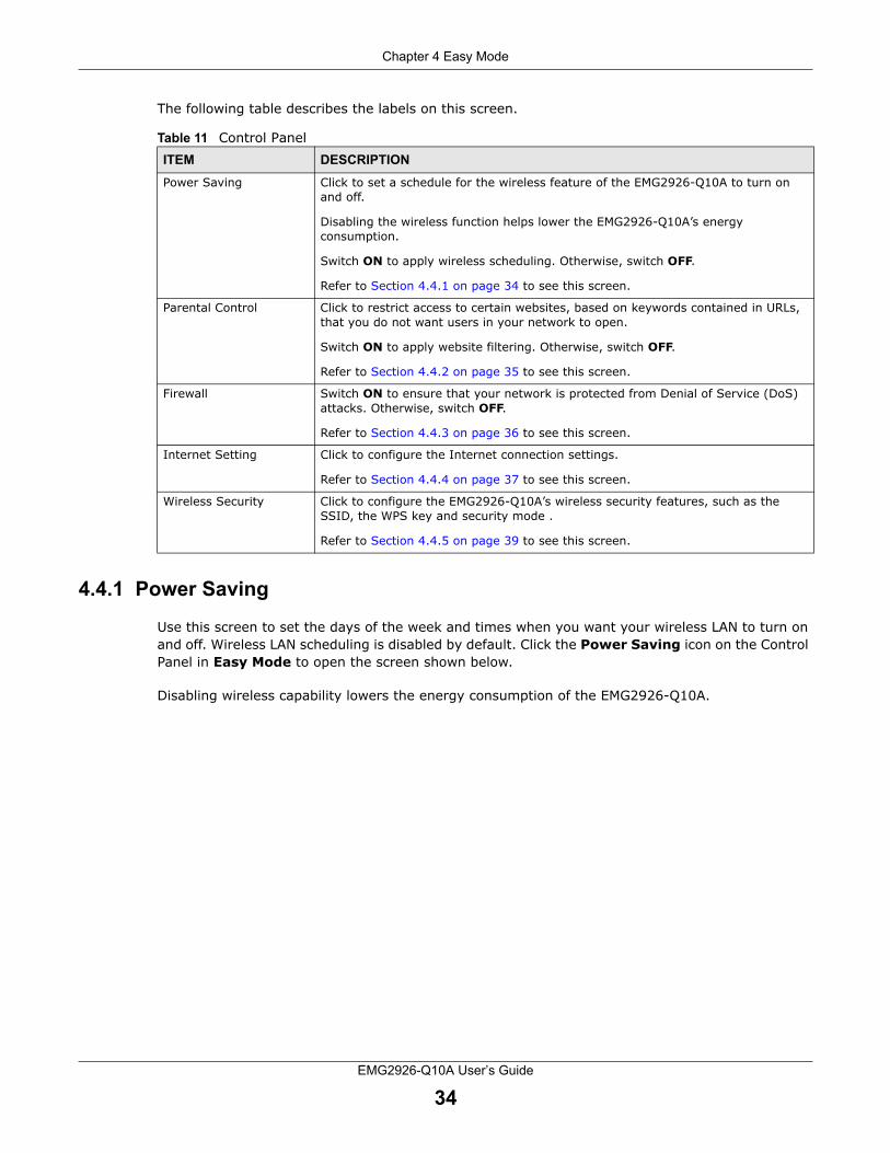
The following table describes the labels on this screen.
4.4.1 Power Saving
Use this screen to set the days of the week and times when you want your wireless LAN to turn on and off. Wireless LAN scheduling is disabled by default. Click the Power Saving icon on the Control Panel in Easy Mode to open the screen shown below.
Disabling wireless capability lowers the energy consumption of the EMG2926-Q10A.
Table 11 Control PanelITEM DESCRIPTION
Power Saving Click to set a schedule for the wireless feature of the EMG2926-Q10A to turn on and off.
Disabling the wireless function helps lower the EMG2926-Q10A’s energy consumption.
Switch ON to apply wireless scheduling. Otherwise, switch OFF.
Refer to Section 4.4.1 on page 34 to see this screen.
Parental Control Click to restrict access to certain websites, based on keywords contained in URLs, that you do not want users in your network to open.
Switch ON to apply website filtering. Otherwise, switch OFF.
Refer to Section 4.4.2 on page 35 to see this screen.
Firewall Switch ON to ensure that your network is protected from Denial of Service (DoS) attacks. Otherwise, switch OFF.
Refer to Section 4.4.3 on page 36 to see this screen.
Internet Setting Click to configure the Internet connection settings.
Refer to Section 4.4.4 on page 37 to see this screen.
Wireless Security Click to configure the EMG2926-Q10A’s wireless security features, such as the SSID, the WPS key and security mode .
Refer to Section 4.4.5 on page 39 to see this screen.
Chapter 4 Easy Mode
EMG2926-Q10A User’s Guide
35
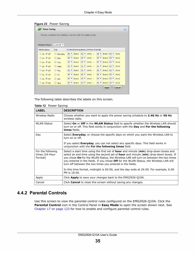
Figure 23 Power Saving
The following table describes the labels on this screen.
4.4.2 Parental Controls
Use this screen to view the parental control rules configured on the EMG2926-Q10A. Click the Parental Control icon in the Control Panel in Easy Mode to open the screen shown next. See Chapter 17 on page 123 for how to enable and configure parental control rules.
Table 12 Power Saving LABEL DESCRIPTION
Wireless Radio Choose whether you want to apply the power saving schedule to 2.4G Hz or 5G Hz wireless radio.
WLAN Status Select On or Off in the WLAN Status field to specify whether the Wireless LAN should turn on or off. This field works in conjunction with the Day and For the following times fields.
Day Select Everyday, or choose the specific days on which you want the Wireless LAN to turn on or off.
If you select Everyday, you can not select any specific days. This field works in conjunction with the For the following times field.
For the following times (24-Hour Format)
Select a start time using the first set of hour and minute (min) drop-down boxes and select an end time using the second set of hour and minute (min) drop-down boxes. If you chose On for the WLAN Status, the Wireless LAN will turn on between the two times you entered in the fields. If you chose Off for the WLAN Status, the Wireless LAN will turn off between the two times you entered in the fields.
In this time format, midnight is 00:00, and the day ends at 24:00. For example, 6:00 PM is 18:00.
Apply Click Apply to save your changes back to the EMG2926-Q10A.
Cancel Click Cancel to close this screen without saving any changes.

Chapter 4 Easy Mode
EMG2926-Q10A User’s Guide
36
Figure 24 Parental Control
The following table describes the labels on this screen.
4.4.3 Firewall
Enable this feature to protect the network from Denial of Service (DoS) attacks. The EMG2926-Q10A blocks repetitive pings from the WAN that can otherwise cause systems to slow down or hang. Click the Firewall icon on the Control Panel in Easy Mode to open the screen shown below. See Chapter 15 on page 117 for how to enable and configure firewall rules.
Table 13 Parental ControlsLABEL DESCRIPTION
Status This label indicates whether the rule is active or not.
A yellow lightbulb signifies that this rule is active. A grey lightbulb signifies that this rule is not active.
Network User (MAC)
This label shows the MAC address of the LAN user’s computer to which this rule applies.
Internet Access Schedule
This label shows the day(s) and time when parental controls are enabled.
Network Service This label shows whether the network service is configured. If not, NONE will be shown.
Website Blocked This label shows whether the website block is configured. If not, NONE will be shown.

Chapter 4 Easy Mode
EMG2926-Q10A User’s Guide
37
Figure 25 Firewall
Click OK to close this screen.
4.4.4 Internet Settings
Use this screen to configure your EMG2926-Q10A for Internet access. You should already have Internet account information from your ISP. The screen varies depending on the Internet connection type you selected. Click the Internet Setting icon on the Control Panel in Easy Mode to open the screen shown next.
Figure 26 Internet Setting (IPoE)

Chapter 4 Easy Mode
EMG2926-Q10A User’s Guide
38
Figure 27 Internet Setting (PPPoE)
The following table describes the labels on this screen.
Table 14 Internet SettingsLABEL DESCRIPTION
Internet Connection Type
Select the IPoE (IP over Ethernet) option when the WAN port is used as a regular Ethernet.
Select the PPPoE (Point-to-Point Protocol over Ethernet) option for a dial-up connection.
The following fields are available if you select IPoE.
Obtain an IP Address Automatically
Select this radio button if your ISP did not assign you a fixed IP address.
Static IP Address Select this radio button if your ISP assigned an IP address for your Internet connection.
IP Address Enter the IP address provided by your ISP.
Subnet Mask Enter the IP subnet mask in this field.
Gateway IP Address
Enter the gateway IP address in this field.
The following fields are available if you select PPPoE.
Get automatically from ISP
Select this radio button if your ISP did not assign you a fixed IP address.
Use Fixed IP Address
Select this radio button to give the EMG2926-Q10A a fixed, unique IP address.
PPP Username Type the user name given to you by your ISP.
PPP Password Type the password associated with the user name above.
My WAN IP Address
Type the name of your service provider.
Cancel Click Cancel to close this screen.
Apply Click Apply to save your changes back to the EMG2926-Q10A.

Chapter 4 Easy Mode
EMG2926-Q10A User’s Guide
39
4.4.5 Wireless Security
Use this screen to configure security for your wireless LAN. You can enter the SSID and select the wireless security mode in the following screen. Click the Wireless Security icon in the control panel of the Easy Mode to open the screen shown below.
Note: You can enable the wireless function of your EMG2926-Q10A by first turning on the switch on the side panel.
Figure 28 Wireless Security
The following table describes the labels on this screen.
Table 15 Wireless SecurityLABEL DESCRIPTION
Wireless Radio Choose whether you want to apply the wireless security to 2.4G Hz or 5G Hz wireless radio.
Wireless Network Name (SSID)
(Service Set Identifier) The SSID identifies the Service Set with which a wireless station is associated. Wireless stations associating to the access point (AP) must have the same SSID. Enter a descriptive name (up to 32 keyboard characters) for the wireless LAN.
Security Mode Select WPA2-PSK to add security on this wireless network. The wireless clients which want to associate to this network must have same wireless security settings as this device. After you select to use a security, additional options appear on this screen.
Select No Security to allow any client to connect to this network without authentication.
Wireless Password
This field appears when you choose WPA2-PSK as the security mode.
Type a pre-shared key from 8 to 63 case-sensitive keyboard characters.
Verify Password Type the password again to confirm.
Apply Click Apply to save your changes to the EMG2926-Q10A.
Cancel Click Cancel to close this screen.
WPS Click to configure the WPS screen.
You can transfer the wireless settings configured here (Wireless Security screen) to another wireless device that supports WPS.

Chapter 4 Easy Mode
EMG2926-Q10A User’s Guide
40
4.4.6 WPS
Use this screen to add a wireless station to the network using WPS. Click WPS in the Wireless Security screen to open the screen shown below.
Figure 29 Wireless Security: WPS
The following table describes the labels on this screen.
4.5 Status Screen in Easy Mode
In the Network Map screen, click Status to view read-only information about the EMG2926-Q10A.
Table 16 Wireless Security: WPSLABEL DESCRIPTION
Wireless Security Click this to go back to the Wireless Security screen.
WPS Create a secure wireless network simply by pressing a button.
The EMG2926-Q10A scans for a WPS-enabled device within the range and performs wireless security information synchronization.
Note: After you click the WPS button on this screen, you have to click on a similar button in the wireless station utility within 2 minutes. To add the second wireless station, you have to press these buttons on both the EMG2926-Q10A and the wireless station again after the first 2 minutes.
Register Create a secure wireless network simply by entering a wireless client's PIN (Personal Identification Number) in the EMG2926-Q10A’s interface and clicking on this button.
Type the same PIN number generated in the wireless station’s utility. Then click Register to associate the two and perform the wireless security information synchronization.
Exit Click Exit to close this screen.

Chapter 4 Easy Mode
EMG2926-Q10A User’s Guide
41
Figure 30 Status Screen in Easy Mode
The following table describes the labels on this screen.
Table 17 Status Screen in Easy ModeITEM DESCRIPTION
Name This is the name of the EMG2926-Q10A on the network.
Time This is the current system date and time.
The date is in YYYY:MM:DD (Year-Month-Day) format. The time is in HH:MM:SS (Hour:Minutes:Seconds) format.
WAN IP This is the IP address of the WAN port.
MAC Address This is the MAC address of the EMG2926-Q10A.
Firmware Version This is the firmware version of the EMG2926-Q10A.
The firmware version format shows the trunk version, model code and release number.
Wireless 2.4G Network Name (SSID)
Wireless 5G Network Name (SSID)
This shows the wireless network’s SSID. You can configure it in the Wireless Security screen (Section 4.4.5 on page 39; Section 9.2 on page 78).
Security This shows the wireless security method used by the EMG2926-Q10A.

EMG2926-Q10A User’s Guide
42
CHAPTER 5
Router Mode
5.1 Overview
The EMG2926-Q10A is set to router mode by default. Routers are used to connect the local network to another network (e.g. the Internet). In the figure below, the EMG2926-Q10A connects the local network (LAN1 ~ LAN4) to the Internet.
Figure 31 EMG2926-Q10A Network
Note: The Status screen appears after you select Expert Mode for the Web Configurator. It varies depending on your EMG2926-Q10A’s device mode.
5.2 Router Mode Status Screen
When you are in Easy Mode, click the Expert Mode icon ( ) in the upper right corner of the screen to enter Expert Mode. Click in Expert Mode to open the status screen.
Modem

Chapter 5 Router Mode
EMG2926-Q10A User’s Guide
43
Figure 32 Status Screen: Router Mode
The following table describes the icons shown on the Status screen.
Table 18 Status Screen IconsICON DESCRIPTION
Click on this icon at any time to exit the Web Configurator.
Click on this icon to view copyright information and access a link to related product information.
Click on this icon to enter Easy Mode. See Chapter 4 on page 31.
Select a number of seconds or None from the drop-down list box to have all screen statistics refresh automatically at the end of each interval or not to have them refresh.
Click this button to refresh the status screen statistics.

Chapter 5 Router Mode
EMG2926-Q10A User’s Guide
44
The following table describes the labels shown on the Status screen.
Click this icon to see the Status page. The information on this screen depends on the device mode you select.
Click this icon to see the Monitor navigation menu.
Click this icon to see the Configuration navigation menu.
Click this icon to see the Maintenance navigation menu.
Table 18 Status Screen Icons (continued)ICON DESCRIPTION
Table 19 Status Screen: Router Mode LABEL DESCRIPTION
Device Information
Host Name This is the System Name to enter in the Maintenance > General screen for identification purposes.
Model Number This is your device’s model number.
Firmware Version This is the firmware version and the date it was created.
Sys OP Mode This is the device mode to which the EMG2926-Q10A is set - Router Mode.
WAN Information
MAC Address This is your device’s WAN Ethernet adapter MAC Address.
IP Address This is the WAN port’s IP address.
IP Subnet Mask This is the WAN port’s subnet mask.
Default Gateway This is the WAN port’s gateway IP address.
IPv6 Address This is the IPv6 address of the EMG2926-Q10A on the WAN.
LAN Information
MAC Address This is the LAN Ethernet adapter MAC Address of your device.
IP Address This is the LAN port’s IP address.
IP Subnet Mask This is the LAN port’s subnet mask.
DHCP This is the LAN port’s DHCP role - Server or Disable.
IPv6 Address This is the IPv6 address of the EMG2926-Q10A on the LAN.
6rd Information
This section is available only when you set IPv6 Tunneling to 6RD in the Network > WAN screen.
IPv6 Address This is the relay server’s IPv6 address.
IP Border Router This is the IPv4 address of the ISP’s border relay server, which helps forward IPv6 packets from the local network to IPv6 networks.
WLAN 2.4G Information
WLAN OP Mode This is the device mode to which the EMG2926-Q10A’s wireless LAN is set - Access Point Mode.
MAC Address This is your device’s 2.4GHz wireless adapter MAC Address.
SSID This is a descriptive name used to identify the EMG2926-Q10A in the 2.4GHz wireless LAN.
Channel This is the channel number selected manually.
Security This is the wireless security level the EMG2926-Q10A is using.
WLAN 5G Information

Chapter 5 Router Mode
EMG2926-Q10A User’s Guide
45
5.2.1 Navigation Panel
Use the sub-menus on the navigation panel to configure the EMG2926-Q10A’s features.
MAC Address This is your device’s 5GHz wireless adapter MAC Address.
SSID This is a descriptive name used to identify the EMG2926-Q10A in the 5GHz wireless LAN.
Channel This is the channel number selected manually.
Security This is the wireless security level the EMG2926-Q10A is using.
Firewall This field indicates whether or not the firewall is enabled.
Summary
Packet Statistics Click on Details... to go to the Monitor > Packet Statistics screen (Section 7.5 on page 66). Use this screen to view the port status and packet-specific statistics.
WLAN 2.4G Station Status
Click on Details... to go to the Monitor > WLAN 2.4G Station Status screen (Section 7.6 on page 67). Use this screen to view the wireless stations that are currently linked to the EMG2926-Q10A’s 2.4GHz wireless LAN.
WLAN 5G Station Status Click on Details... to go to the Monitor > WLAN 5G Station Status screen (Section 7.6 on page 67). Use this screen to view the wireless stations that are currently linked to the EMG2926-Q10A’s 5GHz wireless LAN.
System Status
Item This column displays the type of data the EMG2926-Q10A is recording.
Data This column displays the data currently recorded by the EMG2926-Q10A.
System Up Time This is the total time the EMG2926-Q10A has been on.
Current Date/Time This field displays your EMG2926-Q10A’s current date and time.
System Resource
- CPU Usage This displays what percentage of the EMG2926-Q10A’s processing ability is currently being used. When this percentage is close to 100%, the EMG2926-Q10A is running at full capacity, and the throughput will not improve any further. If you want some applications to have more throughput, you should turn other applications off (by using bandwidth management, for example).
- Memory Usage This field shows the percentage of heap memory the EMG2926-Q10A is using.
Interface Status
Interface This column displays the EMG2926-Q10A port types: WAN, LAN and WLAN.
Status For the LAN and WAN ports, this column indicates whether the line is Down or Up (connected).
For the 2.4GHz/5GHz WLAN, Up is displayed when the 2.4GHz/5GHz WLAN is enabled, while Down is displayed when the 2.4G/5G WLAN is disabled.
Rate For the LAN ports, this column displays the port speed and duplex setting or is left blank when the line is disconnected.
For the WAN port, it displays the port speed and duplex setting if Ethernet encapsulation is used. N/A is displayed when the line is disconnected.
For the 2.4GHz/5GHz WLAN, it displays the maximum transmission rate when the 2.4GHz/5GHz WLAN is enabled. N/A is displayed when the WLAN is disabled.
Table 19 Status Screen: Router Mode (continued) LABEL DESCRIPTION

Chapter 5 Router Mode
EMG2926-Q10A User’s Guide
46
Figure 33 Navigation Panel: Router Mode
The following table describes the sub-menus.
Table 20 Navigation Panel: Router ModeLINK TAB FUNCTION
Status This screen displays the EMG2926-Q10A’s general device, system and interface status information. Use this screen to access summary statistics tables.
MONITOR
Log View Log Use this screen to view a list of activities recorded by your EMG2926-Q10A.
Log Setting Use this screen to select the logs you wish to display.
DHCP Table DHCP Table Use this screen to view current DHCP client information.
IPv6 Neighbor Table
IPv6 Neighbor Table
Use this screen to view IPv6 neighbour information for the EMG2926-Q10A.
Packet Statistics Packet Statistics
Use this screen to view the port status and packet-specific statistics.
WLAN 2.4G Station Status
Association List
Use this screen to view the wireless stations that are currently associated to the EMG2926-Q10A’s 2.4GHz wireless LAN.
WLAN 5G Station Status
Association List
Use this screen to view the wireless stations that are currently associated to the EMG2926-Q10A’s 5GHz wireless LAN.
Internet Sessions
Internet Sessions
Use this screen to view detailed information about active sessions.
DLNA Clients DLNA Clients Use this screen to view information about DLNA-compliant clients on the EMG2926-Q10A’s network.
CONFIGURATION
Network

Chapter 5 Router Mode
EMG2926-Q10A User’s Guide
47
WAN Internet Connection
This screen allows you to configure ISP parameters, WAN IP address assignment, and DNS servers.
Advanced Use this screen to configure other advanced properties.
Wireless LAN 2.4G/5G
General Use this screen to enable the wireless LAN and configure the wireless LAN and wireless security settings.
More AP Use this screen to configure multiple BSSs on the EMG2926-Q10A.
MAC Filter Use the MAC filter screen to configure the EMG2926-Q10A to block access to devices or block devices from accessing the EMG2926-Q10A.
Advanced This screen allows you to configure advanced wireless settings.
QoS Use this screen to configure Wi-Fi Multimedia Quality of Service (WMM QoS). WMM QoS allows you to prioritize wireless traffic according to the delivery requirements of individual services.
WPS Use this screen to configure WPS.
WPS Station Use this screen to add a wireless station using WPS.
Scheduling Use this screen to schedule the times the Wireless LAN will be enabled.
WDS Use this screen to configure the EMG2926-Q10A’s WDS settings.
Channel Status
Use this screen to view the status of all available channels and related information.
LAN IP Use this screen to configure LAN IP address and subnet mask.
IP Alias Use this screen to have the EMG2926-Q10A apply IP alias to create LAN subnets.
IPv6 LAN Use this screen to configure the IPv6 address for the EMG2926-Q10A on the LAN.
Advanced Use this screen to enable the guest LAN and turn on bandwidth management for the guest networks.
DHCP Server General Use this screen to enable the EMG2926-Q10A’s DHCP server.
Advanced Use this screen to assign IP addresses to specific individual computers based on their MAC addresses and to have DNS servers assigned by the DHCP server.
Client List Use this screen to view information related to your DHCP status.
NAT General Use this screen to enable NAT.
Port Forwarding
Use this screen to configure servers behind the EMG2926-Q10A and forward incoming service requests to the server(s) on your local network.
Port Trigger Use this screen to change your EMG2926-Q10A’s port triggering settings.
Dynamic DNS
Dynamic DNS Use this screen to set up dynamic DNS.
Static Route Static Route Use this screen to configure IP static routes.
Security
Firewall General Use this screen to activate/deactivate the firewall.
Services This screen displays a summary of the IPv4 firewall rules, and allows you to edit/add an IPv4 firewall rule.
Content Filter
Content Filter Use this screen to restrict web features and designate a trusted computer.
Table 20 Navigation Panel: Router Mode (continued)LINK TAB FUNCTION

Chapter 5 Router Mode
EMG2926-Q10A User’s Guide
48
Parental Control
Parental Control
Use this screen to configure a restricted access schedule and/or URL filtering settings to block the users on your network from accessing certain websites.
Parental Monitor
Use this screen to set a schedule and have the EMG2926-Q10A send a notification when the specified user connects to the EMG2926-Q10A at the scheduled time.
IPv6 firewall Services Use this screen to configure IPv6 firewall rules.
Management
StreamBoost MGMT
Network Use this screen to view rates of data transmission between the EMG2926-Q10A and the Internet or connected devices.
Bandwidth Use this screen to configure the maximum allowable bandwidth and enable automatic updates.
Priorities Use this screen to change the priority of the connected devices.
Up Time Use this screen to view the top five traffic flows transmitting to/from the selected LAN device(s).
Downloads Use this screen to view the type and percentage of most download traffic.
PerDevice Use this screen to view the percentage of bandwidth used by the connected LAN/WLAN devices.
PerFlow Use this screen to view the percentage of bandwidth used by a traffic flow.
Remote MGMT
WWW Use this screen to configure through which interface(s) and from which IP address(es) users can use HTTP to manage the EMG2926-Q10A.
SNMP Use this screen to change your EMG2926-Q10A’s SNMP settings.
Wake On LAN Use this screen to enable Wake on LAN to remotely turn on a device on the local network.
UPnP General Use this screen to enable UPnP on the EMG2926-Q10A.
USB Media Sharing
DLNA Use this screen to have the EMG2926-Q10A function as a DLNA-compliant media server, that lets DLNA-compliant media clients play video, audio, and photo content files stored on the connected USB storage device.
SAMBA Use this screen to enable file sharing through the EMG2926-Q10A.
FTP Use this screen to have the EMG2926-Q10A act as a FTP server.
Port Configuration
Port Configuration
Use this screen to change the Ethernet port speed and duplex settings.
USB Print Server
Print Server Use this screen to enable the print server function on the EMG2926-Q10A.
Mail My Mail Use this screen to configure the mail server information.
MAINTENANCE
General General Use this screen to view and change administrative settings such as system and domain names.
Account User Account Use this screen to change the password of your EMG2926-Q10A.
Backup/Restore
Backup/Restore
Use this screen to backup and restore the configuration or reset your EMG2926-Q10A to its factory defaults.
Restart System Restart
This screen allows you to reboot the EMG2926-Q10A without turning the power off.
Sys OP Mode Sys OP Mode This screen allows you to select whether your device acts as a router, or an access point.
Table 20 Navigation Panel: Router Mode (continued)LINK TAB FUNCTION

Chapter 5 Router Mode
EMG2926-Q10A User’s Guide
49
Language Language This screen allows you to select the language you prefer.
Diagnostic Ping Use this screen to ping an IP address.
TraceRoute Use this screen to trace the route packets take to a host.
Nslookup Use this screen to perform an Nslookup (name server lookup) to resolve an IP address to a host name and vice versa.
SpeedTest Use this screen to test your Internet connection.
Table 20 Navigation Panel: Router Mode (continued)LINK TAB FUNCTION

EMG2926-Q10A User’s Guide
50
CHAPTER 6
Tutorials
6.1 Overview
This chapter contains tutorials for setting up your EMG2926-Q10A.
• Set Up a Wireless Network with WPS
• Configure Wireless Security without WPS
• Using Multiple SSIDs on the EMG2926-Q10A
6.2 Set Up a Wireless Network with WPS
This section contains an example of how to set up a wireless network using WPS. This example uses the EMG2926-Q10A as the AP and NWD210N as the wireless client that connects to a notebook.
Note: The wireless client must be a WPS-aware device (for example, a WPS USB adapter or PCI card).
There are two WPS methods for creating a secure connection. This tutorial shows you both.
• Push Button Configuration (PBC) - create a secure wireless network simply by pressing a button. See Section 6.2.1 on page 50.This method is easiest.
• PIN Configuration - create a secure wireless network simply by entering a wireless client's PIN (Personal Identification Number) in the EMG2926-Q10A interface. See Section 6.2.2 on page 51. This is a more secure method, as one device can authenticate the other.
6.2.1 Push Button Configuration (PBC)
1 Make sure that your EMG2926-Q10A is turned on, that the WIFI button (on the side panel of the EMG2926-Q10A) is pushed in, and that the device is placed within range of your notebook.
2 Make sure that you have installed the wireless client (this example uses the NWD210N) driver and utility on your notebook.
3 Find the WPS settings in the wireless client utility. Enable WPS and press the WPS button (Start or WPS button)
4 Log into EMG2926-Q10A’s Web Configurator and press the Push Button in the Configuration > Network > Wireless LAN 2.4G > WPS Station screen.

Chapter 6 Tutorials
EMG2926-Q10A User’s Guide
51
Note: Your EMG2926-Q10A has a WPS button located on its panel, as well as a WPS button in its configuration utility. Both buttons have exactly the same function; you can use one or the other.
Note: It doesn’t matter which button is pressed first. You must press the second button within two minutes of the first one.
The EMG2926-Q10A sends the proper configuration settings to the wireless client. This may take up to two minutes. The wireless client is then able to communicate with the EMG2926-Q10A securely.
The figure below shows you an example of how to set up a wireless network and wireless security by pressing a button both on EMG2926-Q10A and in the wireless client (the NWD210N in this example).
Figure 34 Example of WPS Process: PBC Method
6.2.2 PIN Configuration
When you use the PIN configuration method, you need to use both EMG2926-Q10A’s configuration interface and the client’s utilities.
1 Launch your wireless client’s configuration utility. Go to the WPS settings and select the PIN method to get a PIN number.
2 Enter the PIN number in the PIN field in the EMG2926-Q10A’s Configuration > Network > Wireless LAN 2.4G > WPS Station screen.
Wireless Client Access Point
SECURITY INFO
COMMUNICATION
WITHIN 2 MINUTES

Chapter 6 Tutorials
EMG2926-Q10A User’s Guide
52
3 Click on the Start buttons (or button next to the PIN field) in both the wireless client utility screen and the EMG2926-Q10A’s WPS Station screen within two minutes.
The EMG2926-Q10A will authenticate the wireless client and send it the proper configuration settings. This may take up to two minutes. The wireless client will then be able to communicate with the EMG2926-Q10A securely.
The figure below is an example of how to set up a wireless network and wireless security on the EMG2926-Q10A and the wireless client (NWD210N in this example) by using the PIN method.
Figure 35 Example of WPS Process: PIN Method
6.3 Configure Wireless Security without WPS
This is an example of how to configure wireless security settings with the following parameters on your EMG2926-Q10A.
Follow the steps below to configure the wireless settings on your EMG2926-Q10A.
WITHIN 2 MINUTES
Wireless Client Access Point
SSID SSID_Example3
Channel 6
Security WPA2-PSK
(Pre-Shared Key: ThisismyWPA-PSKpre-sharedkey)

Chapter 6 Tutorials
EMG2926-Q10A User’s Guide
53
The instructions require that your hardware be connected (see the Quick Start Guide) and that you be logged into the Web Configurator through your LAN connection (see Section 2.2 on page 18).
1 Make sure the WIFI switch (on the EMG2926-Q10A’s side panel) is set to ON.
2 Open the Configuration > Network > Wireless LAN 2.4G > General screen in the AP’s Web Configurator.
3 Confirm that the wireless LAN is enabled on the EMG2926-Q10A.
4 Enter SSID_Example3 as the SSID and select Channel-06 as the channel. Set security mode to WPA2-PSK and enter ThisismyWPA-PSKpre-sharedkey in the Pre-Shared Key field. Click Apply.

Chapter 6 Tutorials
EMG2926-Q10A User’s Guide
54
5 Open the Status screen. Verify your wireless and wireless security settings under Device Information and check whether the WLAN connection is UP under Interface Status.
6.3.1 Configure Your Notebook
Note: We use the ZyXEL NWD2205 wireless adapter utility screens as an example for the wireless client. The screens may vary for different models.
1 The EMG2926-Q10A supports IEEE 802.11a, IEEE 802.11b, IEEE 802.11g and IEEE 802.11n wireless clients. Make sure that your notebook or desktop computer’s wireless adapter supports one of these standards.
2 Wireless adapters come with software, sometimes called a “utility”, to install on your computer. See your wireless adapter’s User’s Guide for installation information.
3 After you’ve installed the utility, open it. If you cannot see the utility icon on your screen, go to Start > Programs and click on your utility in the list of programs that appears. The utility displays a list of APs within range, as shown in the example screen below.

Chapter 6 Tutorials
EMG2926-Q10A User’s Guide
55
4 Select SSID_Example3 and click Connect.
5 Select AES and type the security key in the following screen. Click Next.
6 The Confirm Save window will appear. Check your settings and click Save to continue.

Chapter 6 Tutorials
EMG2926-Q10A User’s Guide
56
7 Check the status of your wireless connection in the screen below. If your wireless connection is weak, or if you have no connection, see the Troubleshooting section of this guide.
If your connection is successful, open your web browser and enter http://www.zyxel.com or the URL of any other website in the address bar. If you are able to access the website, your wireless connection has been successfully configured.
6.4 Using Multiple SSIDs on the EMG2926-Q10A
You can configure more than one SSID on an EMG2926-Q10A. See Section 9.4 on page 85.
This allows you to configure multiple independent wireless networks on the EMG2926-Q10A as if there were multiple APs (virtual APs). Each virtual AP has its own SSID, wireless security type and MAC filtering settings. That is, each SSID on the EMG2926-Q10A represents a different access point/wireless network for wireless clients in the network.
Clients can only associate with the SSIDs for which they have the correct security settings. Clients using different SSIDs can access the Internet and the wired network behind the EMG2926-Q10A (such as a printer).

Chapter 6 Tutorials
EMG2926-Q10A User’s Guide
57
For example, you may set up three wireless networks (A, B and C) in your office. A is for workers, B is for guests and C is specific to a VoIP device in the meeting room.
6.4.1 Configuring Security Settings for Multiple SSIDs
The EMG2926-Q10A is in router mode by default.
This example shows you how to configure SSIDs with the following parameters on your EMG2926-Q10A (in router mode).
1 Connect your computer to the LAN port of the EMG2926-Q10A using an Ethernet cable.
2 The default IP address of the EMG2926-Q10A in router mode is “192.168.0.1”. In this case, your computer must have an IP address in the range between “192.168.0.2” and “192.168.0.254”.
3 Click Start > Run on your computer (in Windows). Type “cmd” in the dialog box. Enter “ipconfig” to view your computer’s IP address.
4 After you’ve set up your computer’s IP address, open a web browser such as Internet Explorer and type “http://192.168.0.1” as the web address in your web browser.
5 Enter “admin” (default) as the user name and click Login.
6 Type a new password and retype it to confirm, then click Apply. Otherwise, click Ignore.
A
B
C
SSID_Guest
SSID_Worker
SSID_VoIP
SSID SECURITY TYPE KEY MAC FILTERING
SSID_Worker WPA2-PSK
WPA Compatible
DoNotStealMyWirelessNetwork Disable
SSID_VoIP WPA-PSK VoIPOnly12345678 Allow
00:A0:C5:01:23:45
SSID_Guest WPA-PSK keyexample123 Disable

Chapter 6 Tutorials
EMG2926-Q10A User’s Guide
58
7 Easy Mode will appear. Click Expert Mode in the navigation panel.
8 Go to Configuration > Network > Wireless LAN 2.4G > More AP. Click the first entry’s Edit icon to configure wireless and security settings for SSID_Worker.
9 Configure the screen as follows. In this example, Intra-BSS Traffic is enabled for SSID_Worker to allow wireless clients on the same wireless network to communicate with each other. Click Apply.
10 Click the second entry’s Edit icon to configure wireless and security settings for SSID_VoIP.

Chapter 6 Tutorials
EMG2926-Q10A User’s Guide
59
11 Configure the screen as follows. Do not enable Intra-BSS Traffic for SSID_VoIP. Click Apply.
12 Click the third entry’s Edit icon to configure wireless and security settings for SSID_Guest.
13 Configure the screen as follows. In this example, Intra-BSS Traffic is enabled for SSID_Guest to allow wireless clients on the same wireless network to communicate with each other. Select Enable Guest WLAN to allow clients to access the Internet only. Click Apply.
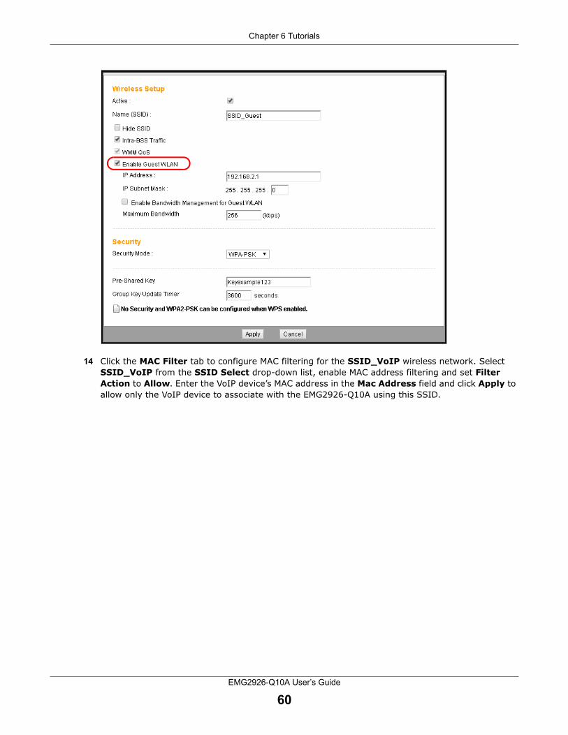
Chapter 6 Tutorials
EMG2926-Q10A User’s Guide
60
14 Click the MAC Filter tab to configure MAC filtering for the SSID_VoIP wireless network. Select SSID_VoIP from the SSID Select drop-down list, enable MAC address filtering and set Filter Action to Allow. Enter the VoIP device’s MAC address in the Mac Address field and click Apply to allow only the VoIP device to associate with the EMG2926-Q10A using this SSID.

Chapter 6 Tutorials
EMG2926-Q10A User’s Guide
61

62
PART IITechnical Reference

EMG2926-Q10A User’s Guide
63
CHAPTER 7
Monitor
7.1 Overview
This chapter discusses read-only information related to the EMG2926-Q10A’s device state.
To access the Monitor screens, go to Expert Mode after login, then click .
You can also click the links in the Summary table on the Status screen to view sent/received packets as well as the status of clients connected to the EMG2926-Q10A.
7.2 The Log Screen
The Web Configurator allows you to view all of the EMG2926-Q10A’s logs in one location and select the logs you wish to display.
7.2.1 View Log
Use the View Log screen to see the EMG2926-Q10A’s logged messages. When the log is full, it deletes older entries one by one to make room for new ones. Select which logs you want to view using the Display drop-down list. Your options will depend upon your settings (Log Setting screen). Click Refresh to refresh the log screen. Click Clear Log to delete all logs.
Figure 36 View Log

Chapter 7 Monitor
EMG2926-Q10A User’s Guide
64
7.2.2 Log Setting
You can configure which logs you want to display on the View Log screen. Go to the Log Setting screen and select the logs you wish to display. Click Apply to save your settings. Click Cancel to start afresh.
Figure 37 Log Setting
7.3 DHCP Table
DHCP (Dynamic Host Configuration Protocol, RFC 2131 and RFC 2132) allows individual clients to obtain TCP/IP configuration at start-up from a server. You can configure the EMG2926-Q10A’s LAN as a DHCP server or disable it. When configured as a server, the EMG2926-Q10A provides TCP/IP configuration for clients. If DHCP service is disabled, you must have another DHCP server on that network, or else the computer must be manually configured.
Go to Monitor > DHCP Table or Configuration > Network > DHCP Server > Client List. This read-only information relates to your DHCP status. The DHCP table shows current DHCP client information (including MAC Address and IP Address) for all network clients that are using the EMG2926-Q10A’s DHCP server.
Figure 38 Monitor > DHCP Table

Chapter 7 Monitor
EMG2926-Q10A User’s Guide
65
The following table describes the labels on this screen.
7.4 IPv6 Neighbor Table
Click Monitor > IPv6 Neighbor Table. Use this screen to view IPv6 neighbor information for the EMG2926-Q10A.
Figure 39 Monitor > IPv6 Neighbor Table
The following table describes the labels on this screen.
Table 21 Monitor > DHCP TableLABEL DESCRIPTION
# This is the host computer’s index number.
Status This field displays whether the connection to the host computer is up (yellow lightbulb) or down (grey lightbulb).
Host Name This field displays the computer’s host name.
IP Address This field displays the IP address corresponding to the # field.
MAC Address This field shows the MAC address of the computer designated in the Host Name field.
Every Ethernet device is identified by a unique MAC (Media Access Control) address. The MAC address is assigned at the factory and consists of six pairs of hexadecimal characters, for example, 00:A0:C5:00:00:02.
Interface This field shows the interface the host computer is connected to.
Reserve Check if you want to reserve the IP address for this specific MAC address.
Apply Click Apply to save your changes to the EMG2926-Q10A.
Cancel Click Cancel to reload the previous configuration for this screen.
Table 22 Monitor > IPv6 Neighbor TableLABEL DESCRIPTION
# This is the neighboring device’s index number.
Link Local Address
This field displays the neighboring device’s link-local IPv6 address.

Chapter 7 Monitor
EMG2926-Q10A User’s Guide
66
7.5 Packet Statistics
Click Monitor > Packet Statistics or Packet Statistics (Details...) in the Status screen. Read-only information here includes port status, packet specific-statistics and "system up time". The Poll Interval(s) field is configurable and is used to refresh the screen.
Figure 40 Monitor > Packet Statistics
MAC Address This field displays the MAC address of the neighboring device.
Status This field displays whether the neighbor IPv6 interface is reachable. In IPv6, “reachable” means that an IPv6 packet can be correctly forwarded to a neighbor node (host or router) and that the neighbor can successfully receive and handle the packet. The available options for this field are:
Reachable: The neighboring device is reachable. (The EMG2926-Q10A has received a response to the initial request.)
Stale: The last reachable time has expired and the EMG2926-Q10A is waiting for a response to another initial request. The field also displays “Stale” when the EMG2926-Q10A receives an unrequested response from the neighboring device.
Delay: The neighboring device is no longer known to be reachable, and traffic has been sent to the neighbor recently. The EMG2926-Q10A delays sending request packets for a short time to give upper-layer protocols a chance to determine reachability.
Probe: The EMG2926-Q10A is sending request packets and waiting for the neighbor’s response.
Incomplete: Address resolution is in progress and the neighbor’s link-layer address has not yet been determined. The neighboring device did not give a complete response.
Table 22 Monitor > IPv6 Neighbor Table (continued)LABEL DESCRIPTION

Chapter 7 Monitor
EMG2926-Q10A User’s Guide
67
The following table describes the labels on this screen.
7.6 WLAN Station Status
Click Monitor > WLAN 2.4G/5G Station Status or the WLAN 2.4G/5G Station Status (Details...) hyperlink in the Status screen to view the Association List, which displays the wireless stations that are currently associated to the EMG2926-Q10A’s 2.4GHz or 5GHz wireless network. Association means that a wireless client (for example, your network or a computer with a wireless network card) has connected successfully to the AP (or wireless router) using the same SSID, channel and security settings.
Figure 41 Monitor > WLAN Station Status
Table 23 Monitor > Packet StatisticsLABEL DESCRIPTION
Port This is the EMG2926-Q10A’s interface type.
Status For the LAN ports, this displays the port speed and duplex setting or Down when the line is disconnected.
For the WAN port, it displays the port speed and duplex setting if Ethernet encapsulation is used and Idle (line (ppp) idle), Dial (starting to trigger a call) and Drop (dropping a call) if PPPoE encapsulation is used. This field displays Down when the line is disconnected.
For the 2.4GHz or 5GHz WLAN, it displays the maximum transmission rate when the WLAN is enabled and Down when the WLAN is disabled.
TxPkts This is the number of transmitted packets on this port.
RxPkts This is the number of received packets on this port.
Collisions This is the number of collisions on this port.
Errors This is the number of received errors on this port.
Tx B/s This displays the transmission speed in bytes per second for this port.
Rx B/s This displays the reception speed in bytes per second for this port.
Up Time This is the total time the EMG2926-Q10A has been on for each session.
System Up Time This is the total time the EMG2926-Q10A has been on.
Poll Interval(s) Enter the time interval in seconds for refreshing statistics in this field.
Set Interval Click this button to apply the new poll interval you entered in the Poll Interval(s) field.
Stop Click Stop to stop refreshing statistics.

Chapter 7 Monitor
EMG2926-Q10A User’s Guide
68
The following table describes the labels on this screen.
7.7 Internet Sessions
Click Monitor > Internet Sessions. Use this screen to view detailed information about active sessions.
Table 24 Monitor > WLAN Station StatusLABEL DESCRIPTION
# This is the index number of an associated wireless station.
Strength This field displays the station’s wireless connection signal strength.
MAC Address This field displays the MAC address of an associated wireless station.
IP Address This field displays the IP address of an associated wireless station.
Device Name This field displays the name of an associated wireless station.
SSID This field displays the name of the EMG2926-Q10A’s wireless network to which the station is connected.
TxPkts This field displays the number of packets transmitted by the station through the wireless connection.
RxPkts This field displays the number of packets received by the station through the wireless connection.
Security This field displays which secure encryption method is being used by the station to connect to the network.
Rate This field displays the wireless station’s transmission rate.
Mode This field displays the wireless standard supported by the wireless station.
Association Time This field displays the time at which a wireless station first associated with the EMG2926-Q10A’s WLAN.

Chapter 7 Monitor
EMG2926-Q10A User’s Guide
69
Figure 42 Monitor > Internet Sessions
The following table describes the labels on this screen.
Table 25 Monitor > Internet SessionsLABEL DESCRIPTION
Internet Sessions Summary
Protocol This field displays the transport layer protocol used in a session.
In This field displays the number of incoming sessions in which TCP or UDP is used.
Out This field displays the number of outgoing sessions in which TCP or UDP is used.
Internet Sessions
Local This field displays the source IP address for each active session.
NAT This field displays the source port for each active session.
Internet This field displays the destination IP address and port for each active session.
Protocol This field displays the protocol used in each active session.
State This field displays the TCP connection state. It displays - for a UDP session.
Dir This field displays the traffic direction for each active session.
Time Out This field displays the number of seconds remaining before a session expires.

Chapter 7 Monitor
EMG2926-Q10A User’s Guide
70
7.8 DLNA Clients
Click Monitor > DLNA Clients. Use this screen to view information about DLNA-compliant clients on the EMG2926-Q10A’s network. See Section 22.2 on page 148 for how to have the EMG2926-Q10A act as a DLNA-compliant media server.
Figure 43 Monitor > DLNA Clients
The following table describes the labels on this screen.
Table 26 Monitor > DLNA ClientsLABEL DESCRIPTION
# This field displays the DLNA-compliant client’s index number.
MAC Address This field displays the DLNA-compliant client’s MAC address.
IP Address This field displays the DLNA-compliant client’s IP address.
Device Name This field displays the DLNA-compliant client’s name.

EMG2926-Q10A User’s Guide
71
CHAPTER 8
WAN
8.1 Overview
This chapter discusses the EMG2926-Q10A’s WAN screens. Use these screens to configure your EMG2926-Q10A for Internet access.
A WAN (Wide Area Network) connection is an outside connection to another network or the Internet. It connects private networks such as a LAN (Local Area Network) to other networks, so that a computer in one location can communicate with computers in other locations.
Figure 44 LAN and WAN

Chapter 8 WAN
EMG2926-Q10A User’s Guide
72
8.2 Internet Connection
Use this screen to change your EMG2926-Q10A’s Internet access settings. Click Network > WAN from the Configuration menu.
Figure 45 Network > WAN > Internet Connection

Chapter 8 WAN
EMG2926-Q10A User’s Guide
73
The following table describes the labels on this screen.
Table 27 Network > WAN > Internet ConnectionLABEL DESCRIPTION
ISP Parameters for Internet Access
Encapsulation You must choose the IPoE option when the WAN port is used as a regular Ethernet.
IPv4 / IPv6 Select IPv4 Only if you want the EMG2926-Q10A to run IPv4 only.
Select Dual Stack to allow the EMG2926-Q10A to run IPv4 and IPv6 at the same time.
Select IPv6 Only if you want the EMG2926-Q10A to run IPv6 only.
IP Address
Obtain an IP Address Automatically
Select this option if your ISP did not assign a fixed IP address. This is the default selection.
Static IP Address Select this option if the ISP assigned a fixed IP address.
IP Address Enter your WAN IP address in this field if you selected Static IP Address.
Subnet Mask Enter the Subnet Mask in this field.
Gateway IP Address
Enter a Gateway IP Address (if your ISP gave you one) in this field.
MTU Size Enter the MTU (Maximum Transmission Unit) size for each packet. If a packet arrives that is larger than the maximum, the EMG2926-Q10A will divide it into smaller fragments.
DHCP Option
Enable DHCP Option 121
Select this to enable the classless route option 121.
Enable DHCP Option 125
Select this to add vendor specific information to the DHCP requests that the EMG2926-Q10A sends to a DHCP server when getting a WAN IP address.
Enable DHCP Option 60
Select this to identify the vendor and functionality of the EMG2926-Q10A in the DHCP requests that the EMG2926-Q10A sends to a DHCP server when getting a WAN IP address.
Vendor ID Enter the Vendor Class Identifier (Option 60), i.e. the type of hardware or firmware.
DNS Server
First DNS Server
Second DNS Server
Third DNS Server
Select Obtained From ISP if your ISP dynamically assigns DNS server information (as well as the EMG2926-Q10A's WAN IP address). The field to the right displays the (read-only) DNS server IP address that the ISP assigns.
Select User-Defined if you have the IP address of a DNS server. Enter the DNS server's IP address in the field to the right.
Select None if you do not want to configure DNS servers. If you do not configure a DNS server, you must know a computer’s IP address in order to access it.
IPv6 Tunneling
Use IPv6 tunneling when the local network uses IPv6 and the ISP has an IPv4 network. When the EMG2926-Q10A has an IPv4 WAN address and you set IPv4/IPv6 mode to IPv4 Only, you can enable IPv6 tunneling to encapsulate IPv6 packets in IPv4 packets to cross the ISP’s IPv4 network.

Chapter 8 WAN
EMG2926-Q10A User’s Guide
74
IPv6 Tunneling Select None to not allow IPv6 packets to cross IPv4 networks.
Select 6RD to enable 6RD. IPv6 Rapid Deployment (6RD) is an IPv6 transitioning process for the stateless tunneling of IPv6 over IPv4. Enable 6RD to tunnel IPv6 traffic from the local network through the ISP’s IPv4 network.
Select 6to4 to transmit IPv6 packets over an IPv4 network. A 6to4 relay router is required to route 6to4 packets to a native IPv6 network.
Select 6in4 if the EMG2926-Q10A has a public IPv4 address and you want to transmit your IPv6 packets to one remote site only whose LAN network is also an IPv6 network. You must know the WAN IP address of the remote gateway.
6RD
The EMG2926-Q10A generates a global IPv6 prefix from its IPv4 WAN address and tunnels IPv6 traffic to the ISP’s Border Relay router to connect to the native IPv6 Internet. The local network can also use IPv4 services. The EMG2926-Q10A uses its configured IPv4 WAN IP to route IPv4 traffic to the IPv4 Internet.
This is only available when IPv4 Only is selected in the IPv6/IPv4 field.
Automatically configured by DHCPC
Select this to have the EMG2926-Q10A detect the relay server’s IP address automatically through DHCP.
Manually Configured Select this if you have the relay server’s IPv4 address.
Border Relay IPv4 Address
Enter the relay server’s IPv4 address.
Service Provider IPv6 Prefix
Enter an IPv6 prefix for tunneling IPv6 traffic to the ISP’s Border Relay router and connecting to the native IPv6 Internet.
Service Provider IPv6 Prefix length
Enter the IPv6 prefix length.
An IPv6 prefix length specifies the number of most significant bits (starting from the left) in the address that compose the network address.
IPv4 mask length Enter the IPv4 network’s subnet mask number (1~32).
6to4
The EMG2926-Q10A should get a public IPv4 address for the WAN. The EMG2926-Q10A adds an IPv4 IP header to an IPv6 packet when transmitting the packet to the Internet. In reverse, the EMG2926-Q10A removes the IPv4 header from an IPv6 packet when receiving it from the Internet.
This is available only when IPv4 Only is selected in the IPv4/IPv6 field.
Relay Server IPv4 Address
Enter the IPv4 address of a 6to4 relay server, which helps forward packets between 6to4 networks and native IPv6 networks.
6in4
The EMG2926-Q10A encapsulates IPv6 packets within IPv4 packets as they travel through the Internet. You must know the remote gateway device’s WAN IP address. This mode is normally used for a site-to-site applications, such as connecting two branch offices.
This is available only when IPv4 Only is selected in the IPv4/IPv6 field.
Remote IPv4 Address
Enter the IPv4 address of the remote gateway to which this interface tunnels traffic.
Remote IPv6 Address
Enter the IPv6 address of the remote gateway to which this interface tunnels traffic.
Local IPv6 Address Enter the IPv6 address assigned by your ISP.
IPv6 Prefix Enter the IPv6 prefix for this interface if you want to use a static IP address.
Table 27 Network > WAN > Internet Connection (continued)LABEL DESCRIPTION

Chapter 8 WAN
EMG2926-Q10A User’s Guide
75
8.3 Advanced WAN Screen
To change your EMG2926-Q10A’s advanced WAN settings, click Network > WAN > Advanced. The screen will appear as shown.
IPv6 DNS server
This is available only when you select IPv4 Only in the IPv4/IPv6 field and set IPv6 Tunneling to 6RD, 6in4 or 6to4.
First DNS Server
Second DNS Server
Third DNS Server
Specify the DNS server IPv6 address assigned by the ISP.
IPv6 Address
This section is not available when you select IPv4 Only in the IPv6/IPv4 field.
Obtain an IP Address Automatically
Select this option if you want to obtain an IPv6 address from a DHCPv6 server.
• Select DUID-LL (Default) to have the EMG2926-Q10A use DUID-LL (DUID Based on Link-layer Address) for identification when exchanging DHCPv6 messages.
• Select DUID-LLT to have the EMG2926-Q10A use DUID-LLT (DUID Based on Link-layer Address Plus Time) for identification when exchanging DHCPv6 messages.
Static IP Address Select this if you have a fixed IPv6 address assigned by your ISP.
IPv6 Address Enter the IPv6 address assigned by your ISP.
Prefix length Enter the address prefix length to specify how many most significant bits in an IPv6 address compose the network address.
IPv6 Default Gateway
Enter the IP address of the next-hop gateway. The gateway is a router or switch on the same segment as your EMG2926-Q10A's interface(s). The gateway helps forward packets to their destinations.
Link Local Only Select this option to use the link-local address, which identifies a device only on the local network (the LAN).
IPv6 DNS server
This is available only when Dual Stack or IPv6 Only is selected in the IPv4/IPv6 field.
First DNS Server
Second DNS Server
Third DNS Server
Select Obtained From ISP to have the EMG2926-Q10A get the IPv6 DNS server addresses from the ISP automatically.
Select User-Defined and enter the IPv6 DNS server address assigned by the ISP to have the EMG2926-Q10A use the IPv6 DNS server addresses you configured manually.
Select None if you do not want to configure DNS servers. If you do not configure a DNS server, you must know the IPv6 address of a computer in order to access it.
Apply Click Apply to save your changes back to the EMG2926-Q10A.
Cancel Click Cancel to begin configuring this screen afresh.
Table 27 Network > WAN > Internet Connection (continued)LABEL DESCRIPTION

Chapter 8 WAN
EMG2926-Q10A User’s Guide
76
Figure 46 Network > WAN > Advanced
The table below describes the labels on this screen.
Table 28 Network > WAN > AdvancedLABEL DESCRIPTION
Multicast Setup
Multicast Select IGMPv1/v2 to enable multicasting. This applies to traffic routed from the WAN to the LAN.
Select None to disable this feature. This may cause incoming traffic to be dropped or sent to all connected network devices.
Auto-Subnet Configuration
Enable Auto-IP-Change Mode
Select this option to have the EMG2926-Q10A change its LAN IP address to either 10.0.0.1 or 192.168.0.1 as needed when the EMG2926-Q10A gets a dynamic WAN IP address in the same subnet as the LAN IP address 192.168.0.1 or 10.0.0.1.
The NAT, DHCP server and firewall functions on the EMG2926-Q10A are still available in this mode.
Apply Click Apply to save your changes back to the EMG2926-Q10A.
Cancel Click Cancel to begin configuring this screen afresh.

EMG2926-Q10A User’s Guide
77
CHAPTER 9
Wireless LAN
9.1 Overview
This chapter discusses how to configure your EMG2926-Q10A’s wireless network settings. The EMG2926-Q10A is able to function on both 2.4GHz and 5GHz networks at the same time. You can also have different wireless and wireless security settings for 2.4GHz and 5GHz wireless LANs. Click Configuration > Network > Wireless LAN 2.4G or Wireless LAN 5G to configure your settings.
See the appendices for more detailed information about wireless networks.
The following figure provides an example of a wireless network.
Figure 47 Example of a Wireless Network
The wireless network is the part in the blue circle. In this wireless network, devices A and B are called wireless clients. The wireless clients use the access point (AP) to interact with other devices (such as the printer) or with the Internet. Your EMG2926-Q10A is the AP.

Chapter 9 Wireless LAN
EMG2926-Q10A User’s Guide
78
9.2 General Wireless LAN Screen
Use this screen to configure the wireless LAN’s SSID and wireless security.
Note: If you are configuring the EMG2926-Q10A from a computer connected to the wireless LAN and you change the EMG2926-Q10A’s SSID, channel or security settings, you will lose your wireless connection when you press Apply to confirm. You must then change the wireless settings of your computer to match the EMG2926-Q10A’s new settings.
Click Network > Wireless LAN 2.4G/5G to open the General screen.
Figure 48 Network > Wireless LAN 2.4G/5G > General
The following table describes the general wireless LAN labels on this screen.
Table 29 Network > Wireless LAN 2.4G/5G > GeneralLABEL DESCRIPTION
Wireless LAN Select Enable to activate the 2.4GHz and/or 5GHz wireless LAN. Select Disable to turn it off.
You can enable or disable both 2.4GHz and 5GHz wireless LANs by using the WIFI button located on the EMG2926-Q10A’s side panel.
Name (SSID) The SSID (Service Set Identifier) identifies the Service Set with which a wireless client is associated. Enter a descriptive name (up to 32 printable characters found on a typical English language keyboard) for the wireless LAN.
Hide SSID Select this check box to hide the SSID in the outgoing beacon frame so a station cannot obtain the SSID by scanning with a site survey tool.
Channel Selection Set the operating frequency/channel according to your particular region.
Select a channel from the drop-down list box. The options vary depending on the frequency band and the country you are in.
Refer to the Connection Wizard chapter for more information on channels. This option is only available if Auto Channel Selection is disabled.

Chapter 9 Wireless LAN
EMG2926-Q10A User’s Guide
79
Auto Channel Selection
Select this check box for the EMG2926-Q10A to automatically choose the channel with the least interference. Deselect this check box if you wish to manually select the channel using the Channel Selection field.
If you select the check box, you can click the Scan Channel button to scan for and choose an available channel immediately.
Operating Channel
This displays the channel the EMG2926-Q10A is currently using.
Channel Width Select the wireless channel width used by the EMG2926-Q10A.
A standard 20 MHz channel provides transfer speeds of up to 144Mbps (2.4GHz) or 217Mbps (5GHZ) whereas a 40MHz channel uses two standard channels and provides speeds of up to 300Mbps (2.4GHz) or 450Mbps (5GHZ). An IEEE 802.11ac-specific 80MHz channel provides speeds of up to 1.3Gbps.
Because not all devices support 40 MHz and/or 80 MHz channels, select Auto 20/40 MHz or Auto 20/40/80 MHz to allow the EMG2926-Q10A to adjust the channel bandwidth automatically.
40 MHz (channel bonding or dual channel) bonds two adjacent radio channels to increase throughput. A 80 MHz channel consists of two adjacent 40 MHz channels. The wireless clients must also support 40 MHz or 80 MHz. In a location where the environment hinders the wireless signal, it is often better to use the 20 MHz setting .
Select 20 MHz if you want to lessen radio interference with other wireless devices in your neighborhood or the wireless clients do not support channel bonding.
802.11 Mode If you are in the Wireless LAN 2.4G > General screen, you can select from the following:
• 802.11b: Allows either IEEE 802.11b- or IEEE 802.11g-compliant WLAN devices to associate with the EMG2926-Q10A. In this mode, all wireless devices can only transmit at the data rates supported by IEEE 802.11b.
• 802.11g: Allows IEEE 802.11g-compliant WLAN devices to associate with the Device. IEEE 802.11b-compliant WLAN devices can associate with the EMG2926-Q10A only when they use the short preamble type.
• 802.11bg: Allows either IEEE 802.11b- or IEEE 802.11g-compliant WLAN devices to associate with the EMG2926-Q10A. The EMG2926-Q10A adjusts the transmission rate automatically according to the wireless standard supported by the wireless devices.
• 802.11n: Allows IEEE 802.11n-compliant WLAN devices to associate with the EMG2926-Q10A. This can increase transmission rates, although IEEE 802.11b or IEEE 802.11g clients will not be able to connect to the EMG2926-Q10A.
• 802.11gn: allows either IEEE 802.11g- or IEEE 802.11n-compliant WLAN devices to associate with the EMG2926-Q10A. The transmission rate of your EMG2926-Q10A might be reduced.
• 802.11 bgn: Allows IEEE802.11b-, IEEE802.11g- and IEEE802.11n-compliant WLAN devices to associate with the EMG2926-Q10A. The transmission rate of your EMG2926-Q10A might be reduced.
If you are in the Wireless LAN 5G > General screen, you can select from the following:
• 802.11a: Allows only IEEE 802.11a-compliant WLAN devices to associate with the EMG2926-Q10A.
• 802.11an: Allows both IEEE802.11n- and IEEE802.11a-compliant WLAN devices to associate with the EMG2926-Q10A. The transmission rate of your EMG2926-Q10A might be reduced.
• 802.11ac: Allows only IEEE 802.11ac-compliant WLAN devices to associate with the EMG2926-Q10A.
Table 29 Network > Wireless LAN 2.4G/5G > General (continued)LABEL DESCRIPTION

Chapter 9 Wireless LAN
EMG2926-Q10A User’s Guide
80
See the rest of this chapter for information on the other labels on this screen.
9.3 Wireless Security
The screen varies depending on what you select in the Security Mode field.
9.3.1 No Security
Select No Security to allow wireless clients to communicate with the access points without any data encryption.
Note: If you do not enable any wireless security on your EMG2926-Q10A, your network is accessible to any wireless networking device that is within range.
Figure 49 Network > Wireless LAN 2.4G/5G > General: No Security
Security Mode Note: If the WPS function is enabled (default), only No Security and WPA2-PSK are available in this field.
Select Static WEP, WPA-PSK, WPA, WPA2-PSK or WPA2 to add security on this wireless network. Wireless clients that want to associate to this network must have same wireless security settings as this device. After you select a security mode, additional options will appear on this screen. See Section 9.3 on page 80 for detailed information on different security modes. Alternatively, you can select No Security to allow any client to associate this network without authentication.
Apply Click Apply to save your changes to the EMG2926-Q10A.
Cancel Click Cancel to reload the previous configuration for this screen.
Table 29 Network > Wireless LAN 2.4G/5G > General (continued)LABEL DESCRIPTION

Chapter 9 Wireless LAN
EMG2926-Q10A User’s Guide
81
The following table describes the labels on this screen.
9.3.2 WEP Encryption
WEP encryption scrambles the data transmitted between the wireless stations and the access points to keep network communications private. It encrypts unicast and multicast communications on a network. Both the wireless stations and the access points must use the same WEP key.
Your EMG2926-Q10A allows you to configure up to four 64-bit or 128-bit WEP keys but only one key can be enabled at any one time.
Select Static WEP from the Security Mode list.
Note: Static WEP is not available if you enable WPS before you configure WEP in the Network> Wireless LAN2.4G/5G > General screen.
Figure 50 Network > Wireless LAN 2.4G/5G > General: Static WEP
Table 30 Network > Wireless LAN 2.4G/5G > General: No SecurityLABEL DESCRIPTION
Security Mode Choose No Security from the drop-down list box.
Apply Click Apply to save your changes with the EMG2926-Q10A.
Cancel Click Cancel to reload the previous configuration for this screen.

Chapter 9 Wireless LAN
EMG2926-Q10A User’s Guide
82
The following table describes the wireless LAN security labels on this screen.
9.3.3 WPA-PSK/WPA2-PSK
Select WPA-PSK or WPA2-PSK from the Security Mode list.
Table 31 Network > Wireless LAN 2.4G/5G > General: Static WEPLABEL DESCRIPTION
Security Mode Select Static WEP to enable data encryption.
PassPhrase Enter a passphrase (up to 26 printable characters) and click Generate.
A passphrase functions like a password. In WEP security mode, it is further converted by the EMG2926-Q10A into a complicated string that is referred to as the “key”. This key is requested from all devices wishing to connect to a wireless network.
WEP Encryption Select 64-bits or 128-bits.
This dictates the length of the security key that the network will use.
Authentication Method
Select Auto or Shared Key from the drop-down list box.
This field specifies whether the wireless clients have to provide the WEP key to log in to the wireless client. Keep this setting at Auto unless you want to force a key verification before communication between the wireless client and the EMG2926-Q10A occurs.
Select Shared Key to force the clients to provide the WEP key prior to communication.
ASCII Select this option in order to enter ASCII characters as a WEP key.
Hex Select this option in order to enter hexadecimal characters as a WEP key.
The prefix "0x", which identifies a hexadecimal key, is entered automatically.
Key 1 to Key 4 The WEP keys are used to encrypt data. Both the EMG2926-Q10A and the wireless stations must use the same WEP key for data transmission.
If you chose 64-bits, enter any 5 ASCII characters or 10 hexadecimal characters ("0-9"; "A-F").
If you chose 128-bits, enter 13 ASCII characters or 26 hexadecimal characters ("0-9"; "A-F").
You must configure at least one key, and only one key can be activated at any one time. The default key is Key 1.
Apply Click Apply to save your changes to the EMG2926-Q10A.
Cancel Click Cancel to reload the previous configuration for this screen.

Chapter 9 Wireless LAN
EMG2926-Q10A User’s Guide
83
Figure 51 Network > Wireless LAN 2.4G/5G > General: WPA-PSK/WPA2-PSK
The following table describes the labels on this screen.
9.3.4 WPA/WPA2
Select WPA or WPA2 from the Security Mode list.
Note: WPA or WPA2 is not available if you enable WPS before you configure WPA or WPA2 in the Wireless LAN 2.4G/5G > General screen.
Table 32 Network > Wireless LAN 2.4G/5G > General: WPA-PSK/WPA2-PSKLABEL DESCRIPTION
Security Mode Select WPA-PSK or WPA2-PSK to enable data encryption.
WPA-PSK Compatible
This field appears when WPA2-PSK is selected as the Security Mode.
Check this field to allow wireless devices using WPA-PSK security mode to connect to your EMG2926-Q10A.
Pre-Shared Key WPA-PSK/WPA2-PSK uses a simple common password for authentication.
Type a pre-shared key made up of 8 to 63 case-sensitive keyboard characters.
Group Key Update Timer
The Group Key Update Timer is the rate at which the AP sends a new group key out to all clients.
The default rate is 3,600 seconds (60 minutes).
Apply Click Apply to save your changes to the EMG2926-Q10A.
Cancel Click Cancel to reload the previous configuration for this screen.

Chapter 9 Wireless LAN
EMG2926-Q10A User’s Guide
84
Figure 52 Network > Wireless LAN 2.4G/5G > General: WPA/WPA2
The following table describes the labels on this screen.
Table 33 Network > Wireless LAN 2.4G/5G > General: WPA/WPA2LABEL DESCRIPTION
Security Mode Select WPA or WPA2 to enable data encryption.
WPA Compatible This check box is available only when you select WPA2-PSK or WPA2 in the Security Mode field.
Select the check box to enable both WPA2 and WPA wireless clients to communicate with the EMG2926-Q10A even when the EMG2926-Q10A is using WPA2-PSK or WPA2.
Group Key Update Timer
The Group Key Update Timer is the rate at which the AP (if using WPA-PSK/WPA2-PSK key management) or RADIUS server (if using WPA/WPA2 key management) sends a new group key out to all clients. The re-keying process is the WPA/WPA2 equivalent of automatically changing the WEP key for an AP and all stations in a WLAN on a periodic basis. You can set the Group Key Update Timer in WPA-PSK/WPA2-PSK mode.
PMK Cache Period This field is only available if you select WPA2.
Specify how often wireless clients have to resend usernames and passwords in order to stay connected. Enter a time interval between 10 and 999,999 minutes.
Note: If wireless client authentication is done using a RADIUS server, the reauthentication timer on the RADIUS server has priority.

Chapter 9 Wireless LAN
EMG2926-Q10A User’s Guide
85
9.4 More AP Screen
This screen allows you to enable and configure multiple wireless networks and guest wireless network settings on the EMG2926-Q10A.
You can configure up to four SSIDs to enable multiple BSSs (Basic Service Sets) on the EMG2926-Q10A. This allows you to use one access point to provide several BSSs simultaneously. You can then assign varying security types to different SSIDs. Wireless clients can use different SSIDs to associate with the same access point.
Click Network > Wireless LAN 2.4G/5G > More AP. The following screen displays:
Figure 53 Network > Wireless LAN 2.4G/5G > More AP
Pre-Authentication This field is available only when you select WPA2.
Pre-authentication enables fast roaming by allowing a wireless client that is already connecting to an AP to perform IEEE 802.1x authentication with another AP before connecting to it. Select Enable to turn on preauthentication in WAP2. Otherwise, select Disable.
Authentication Server
IP Address Enter the IP address of the external authentication server in dotted decimal notation.
Port Number Enter the port number of the external authentication server.
You need not change this value unless your network administrator instructs you to do so with additional information.
Shared Secret Enter a password (up to 127 alphanumeric characters) as the key to be shared between the external authentication server and the EMG2926-Q10A.
The key must be the same on the external authentication server and your EMG2926-Q10A. The key is not sent over the network.
Session Timeout The EMG2926-Q10A automatically disconnects a wireless client from the wireless and wired networks after a period of inactivity. The wireless client then needs to re-send the username and password before it can use the wireless and wired networks again. Some wireless clients may prompt users for a username and password; other clients may use saved login credentials. In either case, there is usually a short delay while the wireless client logs in to the wireless network again.
Enter the time in seconds from 0 to 999,999.
Apply Click Apply to save your changes with the EMG2926-Q10A.
Cancel Click Cancel to reload the previous configuration for this screen.
Table 33 Network > Wireless LAN 2.4G/5G > General: WPA/WPA2 (continued)LABEL DESCRIPTION

Chapter 9 Wireless LAN
EMG2926-Q10A User’s Guide
86
The following table describes the labels on this screen.
9.4.1 More AP Edit
Use this screen to edit an SSID profile. Click the Edit icon next to an SSID in the More AP screen. The following screen will appear.
Figure 54 Network > Wireless LAN 2.4G/5G > More AP: Edit
Table 34 Network > Wireless LAN 2.4G/5G > More APLABEL DESCRIPTION
# This is the index number of each SSID profile.
Status This shows whether the SSID profile is active (a yellow lightbulb) or not (a grey lightbulb).
SSID An SSID profile is the set of parameters relating to one of the EMG2926-Q10A’s BSSs. The SSID (Service Set Identifier) identifies the Service Set with which a wireless device is associated.
This field displays the name of the wireless profile on the network. When a wireless client scans for an AP to associate with, this is the name that is broadcast and displayed in the wireless client utility.
Security This field indicates the SSID profile’s security mode.
Edit Click the Edit icon to configure the SSID profile.

Chapter 9 Wireless LAN
EMG2926-Q10A User’s Guide
87
Figure 55 Network > Wireless LAN 2.4G/5G > More AP: Edit (the last SSID)
The following table describes the labels on this screen.
Table 35 Network > Wireless LAN 2.4G/5G > More AP: EditLABEL DESCRIPTION
Active Select this to activate the SSID profile.
Name (SSID) The SSID (Service Set Identifier) identifies the Service Set with which a wireless client is associated. Enter a descriptive name (up to 32 printable characters found on a typical English language keyboard) for the wireless LAN.
Hide SSID Select this check box to hide the SSID in the outgoing beacon frame so a station cannot obtain the SSID by scanning with a site survey tool.
Intra-BSS Traffic A Basic Service Set (BSS) exists when all communications between wireless clients or between a wireless client and a wired network client go through one access point (AP).
Intra-BSS traffic is traffic between wireless clients in the BSS. When Intra-BSS is enabled, wireless clients can access the wired network and communicate with each other. When Intra-BSS is disabled, wireless clients can still access the wired network but cannot communicate with each other.
WMM QoS Check this to have the EMG2926-Q10A automatically assign a priority level to a service according to the ToS value in the IP header of packets it sends.
WMM QoS (Wifi MultiMedia Quality of Service) gives high priority to voice and video, which makes them run more smoothly.
Enable Guest WLAN
Select the check box to activate guest wireless LAN. This is available only for the last SSID on the EMG2926-Q10A.
Click the Guest Network Bandwidth Management link to go to the LAN > Advanced screen, where you can specify the maximum bandwidth for the guest networks.
The guest LAN and guest WLAN on the EMG2926-Q10A share the same routing domain (192.168.200.0/24) and bandwidth.

Chapter 9 Wireless LAN
EMG2926-Q10A User’s Guide
88
9.5 MAC Filter Screen
The MAC filter screen allows you to configure the EMG2926-Q10A to give exclusive access to devices (Allow) or exclude devices from accessing the EMG2926-Q10A (Deny). Every Ethernet device has a unique MAC (Media Access Control) address. The MAC address is assigned at the factory and consists of six pairs of hexadecimal characters, for example, 00:A0:C5:00:00:02. You need to know the device’s MAC address to configure this screen.
To change your EMG2926-Q10A’s MAC filter settings, click Network > Wireless LAN 2.4G/5G > MAC Filter. The following screen will appear.
Figure 56 Network > Wireless LAN 2.4G/5G > MAC Filter
Security Mode Note: If the WPS function is enabled (default), only No Security and WPA2-PSK are available in this field.
Select Static WEP, WPA-PSK, WPA, WPA2-PSK or WPA2 to add security on this wireless network. Wireless clients that want to connect to this network must have the same wireless security settings as this device. After you select a security mode, additional options will appear in this screen. See Section 9.3 on page 80 for detailed information on different security modes. Alternatively, select No Security to allow any client to associate with this network without authentication.
Apply Click Apply to save your changes to the EMG2926-Q10A.
Cancel Click Cancel to reload the previous configuration for this screen.
Table 35 Network > Wireless LAN 2.4G/5G > More AP: Edit (continued)LABEL DESCRIPTION

Chapter 9 Wireless LAN
EMG2926-Q10A User’s Guide
89
The following table describes the labels on this screen.
9.6 Wireless LAN Advanced Screen
Use this screen to enable advanced wireless features, such as output power, and RTS/CTS Threshold settings.
Click Network > Wireless LAN 2.4G/5G > Advanced. The following screen will appear.
Figure 57 Network > Wireless LAN 2.4G/5G > Advanced
The table below describes the labels on this screen.
Table 36 Network > Wireless LAN 2.4G/5G > MAC FilterLABEL DESCRIPTION
SSID Select Select the SSID for which you want to configure MAC filtering.
MAC Address Filter
Select to turn on (Enable) or off (Disable) MAC address filtering.
Filter Action Define the filter action for the list of MAC addresses in the MAC Filter Summary table.
Select Allow to permit access to the EMG2926-Q10A. MAC addresses not listed will be denied access to the EMG2926-Q10A.
Select Deny to block access to the EMG2926-Q10A. MAC addresses not listed will be allowed to access the EMG2926-Q10A.
MAC Filter Summary
Set This is the index number of the MAC address.
MAC Address Enter the MAC address of the wireless station that is allowed or denied access to the EMG2926-Q10A.
Apply Click Apply to save your changes to the EMG2926-Q10A.
Cancel Click Cancel to reload the previous configuration for this screen.
Table 37 Network > Wireless LAN 2.4G/5G > AdvancedLABEL DESCRIPTION
RTS/CTS Threshold
Data with a frame size larger than this value will perform the RTS (Request To Send)/CTS (Clear To Send) handshake.
This field is not configurable and the EMG2926-Q10A will use the maximum value automatically if you select 802.11n, 802.11an, 802.11gn, 802.11bgn or 802.11ac on the Wireless LAN 2.4G/5G > General screen.

Chapter 9 Wireless LAN
EMG2926-Q10A User’s Guide
90
9.7 Quality of Service (QoS) Screen
The QoS screen allows you to automatically give a service (such as VoIP and video) a priority level.
Click Network > Wireless LAN 2.4G/5G > QoS. The following screen appears:
Figure 58 Network > Wireless LAN 2.4G/5G > QoS
Fragmentation Threshold
The fragmentation boundary’s threshold (number of bytes) for directed messages. It is the maximum data fragment size that can be sent.
This field is not configurable and the EMG2926-Q10A will use the maximum value automatically if you select 802.11n, 802.11an, 802.11gn, 802.11bgn or 802.11ac on the Wireless LAN 2.4G/5G > General screen.
Intra-BSS Traffic A Basic Service Set (BSS) exists when all communications between wireless clients or between a wireless client and a wired network client go through one access point (AP).
Intra-BSS traffic is traffic between wireless clients in the BSS. When Intra-BSS is enabled, wireless clients can access the wired network and communicate with each other. When Intra-BSS is disabled, wireless clients can still access the wired network but cannot communicate with each other.
Short Guard Interval
The guard interval is a gap introduced between users’ data transmission in order to reduce interference. Reducing the interval increases data transfer rates but also increases interference. Increasing the interval reduces data transfer rates but also reduces interference.
Select Enable to use the short guard interval. Otherwise, select Disable to use the long guard interval.
Tx Power Set the output power of the EMG2926-Q10A in this field. If there is a high density of APs in an area, decrease the output power of the EMG2926-Q10A to reduce interference with other APs. Select either 100%, 90%, 75%, 50%, 25% or 10%.
Apply Click Apply to save your changes with the EMG2926-Q10A.
Cancel Click Cancel to reload the previous configuration for this screen.
Table 37 Network > Wireless LAN 2.4G/5G > Advanced (continued)LABEL DESCRIPTION

Chapter 9 Wireless LAN
EMG2926-Q10A User’s Guide
91
The following table describes the labels on this screen.
9.8 WPS Screen
Use this screen to enable/disable WPS, view or generate a new PIN number and check current WPS status. To open this screen, click Network > Wireless LAN 2.4G/5G > WPS.
Note: With WPS, wireless clients can only connect to the wireless network using the first SSID on the EMG2926-Q10A.
Figure 59 Network > Wireless LAN 2.4G/5G > WPS
The following table describes the labels on this screen.
Table 38 Network > Wireless LAN 2.4G/5G > QoSLABEL DESCRIPTION
WMM QoS Select Enable to have the EMG2926-Q10A automatically give a service a priority level according to the ToS value in the IP header of packets it sends. WMM QoS (Wifi Multimedia Quality of Service) gives high priority to voice and video, making them run more smoothly.
This field is not configurable and the EMG2926-Q10A automatically enables WMM QoS if you select 802.11n, 802.11an, 802.11gn, 802.11bgn or 802.11ac in the Wireless LAN 24G/5G > General screen.
Apply Click Apply to save your changes to the EMG2926-Q10A.
Cancel Click Cancel to reload the previous configuration for this screen.
Table 39 Network > Wireless LAN 2.4G/5G > WPSLABEL DESCRIPTION
WPS Setup
WPS Select Enable to turn on the WPS feature. Otherwise, select Disable.
PIN Code Select Enable and click Apply to enable the PIN Configuration method. If you select Disable, you cannot create a new PIN number.

Chapter 9 Wireless LAN
EMG2926-Q10A User’s Guide
92
9.9 WPS Station Screen
Use this screen when you want to add a wireless station using WPS. To open this screen, click Network > Wireless LAN 2.4G/5G > WPS Station tab.
Note: After you click Push Button on this screen, you have to press a similar button in the wireless station utility within 2 minutes. To add the second wireless station, you have to press these buttons on both the EMG2926-Q10A and the wireless station again after the first 2 minutes.
Figure 60 Network > Wireless LAN 2.4G/5G > WPS Station
PIN Number This is the WPS PIN (Personal Identification Number) of the EMG2926-Q10A. Enter this PIN in the configuration utility of the device you want to connect to the EMG2926-Q10A using WPS.
The PIN is not necessary when you use WPS push-button method.
Click Generate to generate a new PIN number.
WPS Status
Status This field displays Configured when the EMG2926-Q10A has connected to a wireless network using WPS or when WPS Enable is selected and wireless or wireless security settings have been changed. The current wireless and wireless security settings also appear on the screen.
This field displays Unconfigured if WPS is disabled and there are no wireless or wireless security changes on the EMG2926-Q10A or you click Release Configuration to remove the configured wireless and wireless security settings.
Release Configuration
This button is only available when the WPS status displays Configured.
Click this button to remove all configured wireless and wireless security settings for WPS connections on the EMG2926-Q10A.
802.11 Mode This is the 802.11 mode that is being used. Only compliant WLAN devices can associate with the EMG2926-Q10A.
SSID This is the name of the wireless network (the EMG2926-Q10A’s first SSID).
Security This is the type of wireless security employed by the network.
Apply Click Apply to save your changes to the EMG2926-Q10A.
Cancel Click Cancel to reload the previous configuration for this screen.
Table 39 Network > Wireless LAN 2.4G/5G > WPS (continued)LABEL DESCRIPTION

Chapter 9 Wireless LAN
EMG2926-Q10A User’s Guide
93
The following table describes the labels on this screen.
9.10 Scheduling Screen
Use this screen to set the times your wireless LAN is turned on and off. Wireless LAN scheduling is disabled by default. The wireless LAN can be scheduled to turn on or off on certain days and at certain times. To open this screen, click Network > Wireless LAN 2.4G/5G > Scheduling tab.
Figure 61 Network > Wireless LAN 2.4G/5G > Scheduling
The following table describes the labels on this screen.
Table 40 Network > Wireless LAN 2.4G/5G > WPS StationLABEL DESCRIPTION
Push Button Use this button when you use the PBC (Push Button Configuration) method to configure the wireless stations’ wireless settings.
Click this to start WPS-aware wireless station scanning and twireless security information synchronization.
Or input station’s PIN number
Use this button when you use the PIN Configuration method to configure the wireless station’s wireless settings.
Type the same PIN number as was generated in the wireless station’s utility. Then click Start to connect and to perform the wireless security information synchronization.
Table 41 Network > Wireless LAN 2.4G/5G > SchedulingLABEL DESCRIPTION
Wireless LAN Scheduling
Wireless LAN Scheduling
Select Enable to activate the wireless LAN scheduling feature. Select Disable to turn it off.
Scheduling
WLAN Status Select On or Off to specify whether you want the wireless LAN to be turned on or off. This field works in conjunction with the Day and For the following times fields.

Chapter 9 Wireless LAN
EMG2926-Q10A User’s Guide
94
9.11 WDS Screen
A Wireless Distribution System (WDS) is a wireless connection between two or more APs. Use this screen to configure the EMG2926-Q10A’s WDS settings. To open this screen, click the Network > Wireless LAN 2.4G/5G > WDS tab. The screen varies depending on the EMG2926-Q10A’s Sys OP Mode.
Note: WDS security is independent of the security settings between the EMG2926-Q10A and any wireless clients.
If you do not enable WDS security, traffic between APs is not encrypted. When WDS security is enabled, both APs must use the same encryption method and pre-shared key.
Figure 62 Network > Wireless LAN 2.4G/5G > WDS (Router Mode)
Figure 63 Network > Wireless LAN 2.4G/5G > WDS (AP Mode)
Day Select Everyday or the specific days you want the wireless LAN to be turned on or off. If you select Everyday you cannot select any specific days. This field works in conjunction with the For the following times field.
For the following times (24-Hour Format)
Select a start time using the first set of hour and minute (min) drop-down boxes and select an end time using the second set of hour and minute (min) drop-down boxes. If you chose On for the WLAN Status, the wireless LAN will turn on between the two times you enter in these fields. If you chose Off for the WLAN Status, the wireless LAN will turn off between the two times you enter in these fields.
Apply Click Apply to save your changes with the EMG2926-Q10A.
Cancel Click Cancel to reload the previous configuration for this screen.
Table 41 Network > Wireless LAN 2.4G/5G > Scheduling (continued)LABEL DESCRIPTION

Chapter 9 Wireless LAN
EMG2926-Q10A User’s Guide
95
The following table describes the labels on this screen.
9.12 Channel Status Screen
Use this screen to display the status of all available channels as well as related information. To open this screen, click the Network > Wireless LAN 2.4G/5G > Channel Status tab.
Click Start to scan for available channels and display the signal strength of each channel. The channel numbers vary depending on the frequency band and the country in which you are using the EMG2926-Q10A.
Figure 64 Network > Wireless LAN 2.4G/5G > Channel Status
Table 42 Network > Wireless LAN 2.4G/5G > WDSLABEL DESCRIPTION
WDS Setup
Basic Setting When the EMG2926-Q10A is in router mode:
• Select Disable to turn off the WDS function on the EMG2926-Q10A.• Select Root AP to allow the EMG2926-Q10A to establish wireless links with other
APs.
When the EMG2926-Q10A is in AP mode:
• Select Disable to turn off the WDS function on the EMG2926-Q10A.• Select Repeater to allow the EMG2926-Q10A to connect to another EMG2926-Q10A
wirelessly in Root AP mode.
Remote SSID This field is available only when you set the EMG2926-Q10A to function as an AP in the Maintenance > Sys OP Mode screen.
Enter the main SSID of an EMG2926-Q10A in Router Mode and Root AP mode, to which you want the EMG2926-Q10A in Repeater mode to connect.
Security
This section is available only when you set the EMG2926-Q10A to work in AP mode in the Maintenance > Sys OP Mode screen.
Security Mode Select Static WEP, WPA-PSK, or WPA2-PSK to use security for your WDS connection. Otherwise, select No Security to disable WDS security.
Note: The security mode and encryption key must be the same as those used for the main SSID on the root AP.
Pre-Shared Key Enter the key used to encrypt data. Peers must use the same key for data transmission.
Authentication Method
Keep this setting at Auto or select Shared Key to provide the WEP key prior to communication.
Key 1 ~ Key 4 Enter the same WEP key for data transmission.
Apply Click Apply to save your changes with the EMG2926-Q10A.
Reset Click Reset to reload the previous configuration for this screen.

Chapter 9 Wireless LAN
EMG2926-Q10A User’s Guide
96
You can click the > or < icon to show or hide the list of wireless networks that are using the channel.
Figure 65 Network > Wireless LAN 2.4G/5G > Channel Status: Scan Result

EMG2926-Q10A User’s Guide
97
CHAPTER 10
LAN
10.1 Overview
This chapter describes how to configure LAN settings.
A Local Area Network (LAN) is a shared communication system to which many computers are attached. A LAN is a computer network limited to the immediate area, usually the same building or floor of a building.
Figure 66 LAN Example
The LAN screens can help you configure a management IP address, and partition your physical network into logical networks.
10.2 LAN IP Screen
Use this screen to change the IPv4 address for your EMG2926-Q10A. Click Network > LAN > IP.
Figure 67 Network > LAN > IP

Chapter 10 LAN
EMG2926-Q10A User’s Guide
98
The following table describes the labels on this screen.
10.3 IP Alias Screen
Use this screen to have the EMG2926-Q10A use IP aliasing to create LAN subnets. Click LAN > IP Alias.
Figure 68 Network > LAN > IP Alias
The following table describes the labels on this screen.
Table 43 Network > LAN > IPLABEL DESCRIPTION
IP Address Type your EMG2926-Q10A’s IP address in dotted decimal notation.
IP Subnet Mask The subnet mask specifies the network number portion of an IP address. Your EMG2926-Q10A will automatically calculate the subnet mask based on the IP address you have entered. Unless you are implementing subnetting, use the subnet mask computed by the EMG2926-Q10A.
MTU Size Enter the maximum size in bytes of each data packet that can move through the interface. If a larger packet arrives, the EMG2926-Q10A will divide it into smaller fragments.
Enable DHCP Option 67
Select this option to have the EMG2926-Q10A (acting as the DHCP server) provide DHCP clients with the boot file path.
Boot File Name Specify the name of the boot file you want the DHCP clients to use.
Apply Click Apply to save your changes to the EMG2926-Q10A.
Cancel Click Cancel to begin configuring this screen afresh.
Table 44 Network > LAN > IP AliasLABEL DESCRIPTION
IP Alias 1, 2 Check this to enable IP aliasing to configure another LAN network for the EMG2926-Q10A.
IP Address Type the IP alias address of your EMG2926-Q10A in dotted decimal notation.
IP Subnet Mask The subnet mask specifies the network number portion of an IP address. Your EMG2926-Q10A will automatically calculate the subnet mask based on the IP address you have entered. Unless you are implementing subnetting, use the subnet mask computed by the EMG2926-Q10A.

Chapter 10 LAN
EMG2926-Q10A User’s Guide
99
10.4 IPv6 LAN Screen
Use this screen to configure the IPv6 address for your EMG2926-Q10A on the LAN. Click Network > LAN > IPv6 LAN.
Figure 69 Network > LAN > IPv6 LAN
The following table describes the labels on this screen.
Apply Click Apply to save your changes to the EMG2926-Q10A.
Cancel Click Cancel to begin configuring this screen afresh.
Table 44 Network > LAN > IP Alias (continued)LABEL DESCRIPTION
Table 45 Network > LAN > IPv6 LAN LABEL DESCRIPTION
Minimum RA period Enter the minimum time in seconds between router advertisement messages.
Router advertisement (RA) is a response to a router solicitation or to a periodical multicast advertisement from a router to advertise its presence and other parameters. The router in router advertisements can be used as a default router.
Enable DHCPv6-PD Select this option to use DHCPv6 prefix delegation. The EMG2926-Q10A will obtain an IPv6 prefix from the ISP or a connected uplink router for the LAN.
Autoconfiguration Type
Select SLAAC (Stateless Address Autoconfiguration) + RDNSS (Recursive DNS Server) to enable IPv6 stateless autoconfiguration on this interface. The interface will generate an IPv6 address from a prefix obtained from an IPv6 router in the network.
Select SLAAC + Stateless DHCPv6 to enable IPv6 stateless auto-configuration on this interface. The interface will get an IPv6 address from an IPv6 router. Hosts use DHCPv6 to obtain additional configuration settings, such as DNS information.
Select Stateful DHCPv6 to allow a DHCPv6 server to assign and transfer IPv6 network addresses, prefixes and other configuration information to DHCPv6 clients.
IPv6 Address range(Start)
If you select Stateful DHCPv6, specify the range of IPv6 addresses from which the DHCPv6 server assigns to the clients. Enter the smallest value of the last block of IPv6 addresses to be allocated.

Chapter 10 LAN
EMG2926-Q10A User’s Guide
100
10.5 LAN Advanced Screen
Use this screen to enable the guest LAN and turn on bandwidth management for guest networks. Click LAN > Advanced.
Figure 70 Network > LAN > Advanced
IPv6 Address range(End)
If you select Stateful DHCPv6, specify the range of IPv6 addresses from which the DHCPv6 server assigns to the clients. Enter the largest value of the last block of IPv6 addresses to be allocated.
IPv6 Lifetime If you select Stateful DHCPv6, specify how long (in seconds) you wish the IPv6 addresses to remain valid.
Static IP Address Select this option to manually enter an IPv6 address if you want to use a static IPv6 address.
LAN IPv6 Address
Enter the static IPv6 address for the EMG2926-Q10A on the LAN.
LAN IPv6 Prefix Length
Enter an IPv6 prefix length that specifies how many most significant bits (start from the left) in the address compose the network address.
Prefix Preferred Lifetime
Enter how long (in seconds) you wish addresses generated from the prefix via stateless address autoconfiguration to remain preferred.
Prefix Valid Lifetime
Enter how long (in seconds) you wish prefix to be valid for on-link determination.
Link Local Only Select this option to use the EMG2926-Q10A’s IPv6 link-local address on the LAN.
ULA Select this option to use the EMG2926-Q10A’s IPv6 Unique Local Address (ULA).
An IPv6 unique local address has a prefix of FC00::/7 and is similar to the blocks of IPv4 addresses for private networks, such as 10.0.0.0/8, 172.16.0.0/12 or 192.168.0.0/16.
Apply Click Apply to save your changes to the EMG2926-Q10A.
Cancel Click Cancel to begin configuring this screen afresh.
Table 45 Network > LAN > IPv6 LAN (continued)LABEL DESCRIPTION

Chapter 10 LAN
EMG2926-Q10A User’s Guide
101
The following table describes the labels on this screen.
Table 46 Network > LAN > AdvancedLABEL DESCRIPTION
Enable Guest LAN Select this option to use the 4th LAN port as the guest LAN.
Devices connected to the guest LAN (port 4) will still be able to communicate with devices connected to other interfaces on the EMG2926-Q10A.
The guest LAN and guest WLAN on the EMG2926-Q10A share the same routing domain (192.168.200.0/24) and bandwidth.
Enable Guest WLAN/LAN Bandwidth Management
Select this option to turn on bandwidth management for the guest networks.
Maximum Bandwidth
Enter a number to specify maximum bandwidth the guest networks can use.
Apply Click Apply to save your changes to the EMG2926-Q10A.
Cancel Click Cancel to begin configuring this screen afresh.
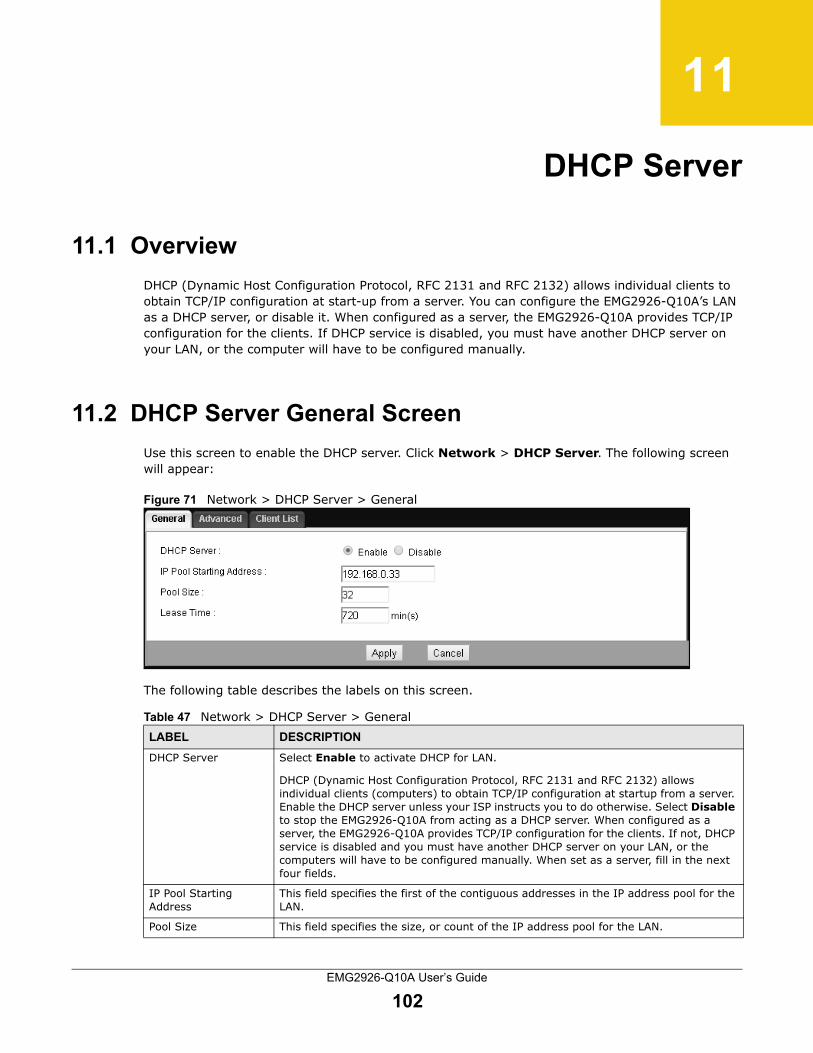
EMG2926-Q10A User’s Guide
102
CHAPTER 11
DHCP Server
11.1 Overview
DHCP (Dynamic Host Configuration Protocol, RFC 2131 and RFC 2132) allows individual clients to obtain TCP/IP configuration at start-up from a server. You can configure the EMG2926-Q10A’s LAN as a DHCP server, or disable it. When configured as a server, the EMG2926-Q10A provides TCP/IP configuration for the clients. If DHCP service is disabled, you must have another DHCP server on your LAN, or the computer will have to be configured manually.
11.2 DHCP Server General Screen
Use this screen to enable the DHCP server. Click Network > DHCP Server. The following screen will appear:
Figure 71 Network > DHCP Server > General
The following table describes the labels on this screen.
Table 47 Network > DHCP Server > General LABEL DESCRIPTION
DHCP Server Select Enable to activate DHCP for LAN.
DHCP (Dynamic Host Configuration Protocol, RFC 2131 and RFC 2132) allows individual clients (computers) to obtain TCP/IP configuration at startup from a server. Enable the DHCP server unless your ISP instructs you to do otherwise. Select Disable to stop the EMG2926-Q10A from acting as a DHCP server. When configured as a server, the EMG2926-Q10A provides TCP/IP configuration for the clients. If not, DHCP service is disabled and you must have another DHCP server on your LAN, or the computers will have to be configured manually. When set as a server, fill in the next four fields.
IP Pool Starting Address
This field specifies the first of the contiguous addresses in the IP address pool for the LAN.
Pool Size This field specifies the size, or count of the IP address pool for the LAN.

Chapter 11 DHCP Server
EMG2926-Q10A User’s Guide
103
11.3 DHCP Server Advanced Screen
This screen allows you to assign IP addresses on the LAN to specific individual computers based on their MAC addresses. You can also use this screen to configure the DNS server information that the EMG2926-Q10A sends to DHCP clients.
To change your EMG2926-Q10A’s static DHCP settings, click Network > DHCP Server > Advanced. The following screen will appear:
Figure 72 Network > DHCP Server > Advanced
The following table describes the labels on this screen.
Lease Time Specify how long each computer can use the IP address before it has to request the information again.
Apply Click Apply to save your changes to the EMG2926-Q10A.
Cancel Click Cancel to begin configuring this screen afresh.
Table 47 Network > DHCP Server > General (continued) LABEL DESCRIPTION
Table 48 Network > DHCP Server > AdvancedLABEL DESCRIPTION
Static DHCP Table
# This is the static IP table entry (row)’s index number.

Chapter 11 DHCP Server
EMG2926-Q10A User’s Guide
104
11.4 DHCP Client List Screen
The DHCP table shows current DHCP client information (including IP Address, Host Name and MAC Address) of network clients using the EMG2926-Q10A’s DHCP servers.
Configure this screen to always assign an IP address to a MAC address (and host name). Click Network > DHCP Server > Client List.
Note: You can also view a read-only client list by clicking Monitor > DHCP Server.
MAC Address Type the MAC address (with colons) of a computer on your LAN.
IP Address Type the LAN IP address of a computer on your LAN.
DNS Server
DNS Servers Assigned by DHCP Server
The EMG2926-Q10A sends a DNS (Domain Name System) server IP address (in the order you specify here) to the DHCP clients. The EMG2926-Q10A only sends this information to the LAN DHCP clients when you enable DHCP Server. When you disable DHCP Server, DHCP service is disabled and you must have another DHCP server on your LAN, or else the computers must have their DNS server addresses manually configured.
First DNS Server
Second DNS Server
Third DNS Server
Select Obtained From ISP if your ISP assigns DNS server information (and the EMG2926-Q10A's WAN IP address) dynamically. The field to the right displays the (read-only) DNS server IP address assigned by the ISP.
Select User-Defined if you have the IP address of a DNS server. Enter the DNS server's IP address in the field to the right. If you chose User-Defined, but leave the IP address set to 0.0.0.0, User-Defined will change to None after you click Apply. If you set a second choice to User-Defined, and enter the same IP address, the second User-Defined changes to None after you click Apply.
Select DNS Relay to have the EMG2926-Q10A act as a DNS proxy. The EMG2926-Q10A's LAN IP address displays in the field to the right (read-only). The EMG2926-Q10A tells the DHCP clients on the LAN that the EMG2926-Q10A itself is the DNS server. When a computer on the LAN sends a DNS query to the EMG2926-Q10A, the EMG2926-Q10A forwards the query to the EMG2926-Q10A's system DNS server (configured in the WAN > Internet Connection screen) and relays the response back to the computer. You can only select DNS Relay for one of the three servers; if you select DNS Relay for a second or third DNS server, your selection will change to None after you click Apply.
Select None if you do not want to configure DNS servers. If you do not configure a DNS server, you must know the IP address of a computer in order to access it.
Apply Click Apply to save your changes to the EMG2926-Q10A.
Cancel Click Cancel to begin configuring this screen afresh.
Table 48 Network > DHCP Server > Advanced (continued)LABEL DESCRIPTION

Chapter 11 DHCP Server
EMG2926-Q10A User’s Guide
105
Figure 73 Network > DHCP Server > Client List
The following table describes the labels on this screen.
Table 49 Network > DHCP Server > Client ListLABEL DESCRIPTION
# This is the host computer’s index number.
Status This field displays whether the connection to the host computer is up (yellow lightbulb) or down (grey lightbulb).
Host Name This field displays the computer host name.
IP Address This field displays the IP address relative to the # field listed above.
MAC Address This field shows the MAC address of the computer with the name in the Host Name field.
Every Ethernet device has a unique MAC (Media Access Control) address which uniquely identifies a device. The MAC address is assigned at the factory and consists of six pairs of hexadecimal characters, for example, 00:A0:C5:00:00:02.
Reserve Select this if you want to reserve the IP address for this specific MAC address.
Apply Click Apply to save your changes to the EMG2926-Q10A.
Cancel Click Cancel to reload the previous configuration for this screen.

EMG2926-Q10A User’s Guide
106
CHAPTER 12
NAT
12.1 Overview
NAT (Network Address Translation - NAT, RFC 1631) is the translation of the IP address of a host in a packet. For example, the source address of an outgoing packet used within one network is changed to a different IP address known within another network.
The figure below is a simple illustration of a NAT network. You want to assign ports 21-25 to one FTP, Telnet and SMTP server (A in the example), port 80 to another (B in the example) and assign a default server IP address of 192.168.0.35 to a third (C in the example).
You assign the LAN IP addresses to the devices (A to D) connected to your EMG2926-Q10A. The ISP assigns the WAN IP address. The NAT network appears as a single host on the Internet. All traffic that comes from A to D and goes out to the Internet uses the EMG2926-Q10A’s IP address, which is 192.168.0.1.
Figure 74 NAT Example
This chapter discusses how to configure NAT on the EMG2926-Q10A.
Note: You must create a firewall rule in addition to setting up NAT in order to allow traffic from the WAN to be forwarded through the EMG2926-Q10A.
A: 192.168.0.33
B: 192.168.0.34
C: 192.168.0.35
IP address
192.168.0.1
WANLAN
assigned by ISP
FTP, Telnet, SNMP
Port 80
Ports 21 to 25

Chapter 12 NAT
EMG2926-Q10A User’s Guide
107
12.2 NAT General Screen
Use this screen to enable NAT and set a default server. Click Network > NAT to open the General screen.
Figure 75 Network > NAT > General
The following table describes the labels on this screen.
12.3 Port Forwarding Screen
Use this screen to forward incoming service requests to the server(s) on your local network and set a default server. You can enter a single port number (or a range of port numbers) to be forwarded as well as the local IP address of the desired server. The port number identifies a service; for example, web service is on port 80, and FTP is on port 21. In some cases, such as for unknown services or instances where one server can support more than one service (such as both FTP and web service), it might be better to specify a range of port numbers.
In addition to the servers used for specified services, NAT supports a default server. A service request that does not have a server explicitly designated to it is forwarded to the default server. If a default has not been designated, the service request is simply discarded.
Note: Many residential broadband ISP accounts do not allow you to run any server processes (such as a Web or FTP server) from your location. Your ISP may periodically check for servers and may suspend your account if it discovers any active services at your location. If you are unsure, consult your ISP.
Port forwarding allows you to define the local servers to which incoming services will be forwarded. To change your EMG2926-Q10A’s port forwarding settings, click Network > NAT > Port Forwarding. The screen will appear as shown below.
Note: If you do not assign a Default Server, the EMG2926-Q10A will discard all packets received for ports that are not specified in this screen or in remote management.
Table 50 Network > NAT > GeneralLABEL DESCRIPTION
Network Address Translation (NAT)
Network Address Translation (NAT) allows the translation of an Internet protocol address used within one network (such as a private IP address used in a local network) to a different IP address known within another network (such as a public IP address used on the Internet).
Select Enable to activate NAT. Select Disable to turn it off.
Apply Click Apply to save your changes to the EMG2926-Q10A.
Cancel Click Cancel to begin configuring this screen afresh.

Chapter 12 NAT
EMG2926-Q10A User’s Guide
108
Figure 76 Network > NAT > Port Forwarding
The following table describes the labels on this screen.
Table 51 Network > NAT > Port ForwardingLABEL DESCRIPTION
Default Server Setup
Default Server In addition to the servers for specified services, NAT supports a default server. A default server receives packets from ports that are not specified on the Port Forwarding screen. You can decide whether you want to use the default server or specify a server manually.
Select this to use the default server.
Change to Server Select this and enter the server’s IP address manually.
Service Name Select a pre-defined service in the second field beside Service Name. The pre-defined service port number(s) and protocol will appear in the port forwarding summary table.
Otherwise, select User define and type a name (made up of up to 31 printable characters) in the first field beside Service Name to specify this rule. You will need to enter the port number(s) manually and select the IP protocol.
Service Protocol Select the transport layer protocol supported by this virtual server. Choose between TCP, UDP, or TCP_UDP.
If you have chosen a pre-defined service in the Service Name field, this field will not be available.
Port Range Type the first and last internal port number that identifies a service.
Translation Port Range
Type the first and last external port number that identifies a service.

Chapter 12 NAT
EMG2926-Q10A User’s Guide
109
12.3.1 Port Forwarding Edit Screen
This screen lets you edit a port forwarding rule. Click a rule’s Edit icon on the Port Forwarding screen to open the following screen:
Figure 77 Network > NAT > Port Forwarding Edit
Server IP Address Select a DHCP client as the virtual server and click Add to add it in the port forwarding summary table.
Otherwise, select Custom and manually enter the inside IP address of the virtual server here.
# This is the index number of an individual port forwarding server entry.
Status This icon is turned on when the rule is enabled.
Name This field displays a name identifying the rule.
Protocol This is the transport layer protocol used for the service.
WAN Interface This is the rule’s WAN interface.
Port This is the internal port number(s) that identifies the service.
Translation Port Range
This is the external port number(s) that identifies the service.
Server IP Address This field displays the server’s inside IP address.
Modify Click the Edit icon to open the edit screen where you can modify an existing rule.
Click the Delete icon to remove a rule.
Apply Click Apply to save your changes to the EMG2926-Q10A.
Cancel Click Cancel to begin configuring this screen afresh.
Table 51 Network > NAT > Port Forwarding (continued)LABEL DESCRIPTION

Chapter 12 NAT
EMG2926-Q10A User’s Guide
110
The following table describes the labels on this screen.
Table 52 Network > NAT > Port Forwarding EditLABEL DESCRIPTION
Port Forwarding Select Enable to turn on this rule and the requested service can be forwarded to the host with a specified internal IP address.
Select Disable to disallow forwarding of these ports to an inside server without having to delete the entry.
Service Name Type a name (of up to 31 printable characters) to identify this rule in the first field beside Service Name. Otherwise, select a predefined service in the second field beside Service Name.
Protocol Select the transport layer protocol supported by this virtual server. Choices are TCP, UDP, or TCP_UDP.
If you have chosen a pre-defined service in the Service Name field, the protocol will be configured automatically.
Port Range Type an internal port number(s) to define the service to be forwarded to the specified server.
To specify a range of ports, enter the first and last port.
Translation Port Range
Type the first and last external port number that identifies a service.
Server IP Address
Type the IP address of the server on your LAN that receives packets from the port(s) specified in the Port field.
Back Click Back to return to the previous screen.
Apply Click Apply to save your changes with the EMG2926-Q10A.
Cancel Click Cancel to begin configuring this screen afresh.

Chapter 12 NAT
EMG2926-Q10A User’s Guide
111
12.4 Port Trigger Screen
To change your EMG2926-Q10A’s port trigger settings, click Network > NAT > Port Trigger. The screen will appear as shown below.
Note: Only one LAN computer can use a trigger port (range) at a time.
Figure 78 Network > NAT > Port Trigger
The following table describes the labels on this screen.
Table 53 Network > NAT > Port TriggerLABEL DESCRIPTION
# This is the rule’s index number (read-only).
Name Enter a unique name (up to 15 characters) for identification purposes. All characters are permitted (including spaces).
Incoming Incoming is a port (or a range of ports) that a server on the WAN uses when it sends out a particular service. With this port (or range of ports), the EMG2926-Q10A forwards the traffic to the client computer on the LAN that requested the service.
Port Enter a port number, or the starting port number in a range of port numbers.
End Port Enter a port number, or the last port number in a range of port numbers.
Trigger The trigger port is a port (or a range of ports) that causes (or triggers) the EMG2926-Q10A to record the IP address of the LAN computer that sent the traffic to a server on the WAN.
Port Enter a port number, or the starting port number in a range of port numbers.
End Port Enter a port number, or the last port number in a range of port numbers.

Chapter 12 NAT
EMG2926-Q10A User’s Guide
112
Apply Click Apply to save your changes to the EMG2926-Q10A.
Cancel Click Cancel to begin configuring this screen afresh.
Table 53 Network > NAT > Port Trigger (continued)LABEL DESCRIPTION

EMG2926-Q10A User’s Guide
113
CHAPTER 13
DDNS
13.1 Overview
DDNS services let you use a domain name with a dynamic IP address.
13.2 General
To change your EMG2926-Q10A’s DDNS, click Network > DDNS. The screen will appear as shown.
Figure 79 Dynamic DNS
The following table describes the labels on this screen.
Table 54 Dynamic DNSLABEL DESCRIPTION
Dynamic DNS Select Enable to use dynamic DNS. Select Disable to turn this feature off.
Service Provider Select the name of your Dynamic DNS service provider.
Host Name Enter a host name in the field provided. You can specify up to two host names in the field if you separated them with a comma (",").
Username Enter your user name.
Password Enter the password assigned to you.
Apply Click Apply to save your changes to the EMG2926-Q10A.
Cancel Click Cancel to begin configuring this screen afresh.

EMG2926-Q10A User’s Guide
114
CHAPTER 14
Static Route
14.1 Overview
This chapter shows you how to configure static routes for your EMG2926-Q10A.
The EMG2926-Q10A usually uses the default gateway to route outbound traffic from computers on the LAN to the Internet. To have the EMG2926-Q10A send data to devices not reachable through the default gateway, use static routes.
For example, the following figure shows a computer (A) connected to the EMG2926-Q10A’s LAN interface. The EMG2926-Q10A routes most traffic from A to the Internet through the EMG2926-Q10A’s default gateway (R1). You have created one static route to connect to services offered by your ISP behind router R2. You have created another static route to communicate with a separate network behind router R3 connected to the LAN.
Figure 80 Example of Static Routing Topology
14.2 IP Static Route Screen
Click Network > Static Route to open the Static Route screen.
WAN
R1
R2
A
R3
LAN

Chapter 14 Static Route
EMG2926-Q10A User’s Guide
115
Figure 81 Network > Static Route
The following table describes the labels on this screen.
14.2.1 Add/Edit Static Route
Click the Add Static Route button or a rule’s Edit icon in the Static Route screen. Use this screen to configure the information required for a static route.
Figure 82 Network > Static Route: Add/Edit
The following table describes the labels on this screen.
Table 55 Network > Static RouteLABEL DESCRIPTION
Add Static Route Click this to create a new rule.
# This is the number of an individual static route.
Status This field indicates whether the rule is active (yellow lightbulb) or not (grey lightbulb).
Name This field displays a name to identify this rule.
Destination This parameter specifies the IP network address of the final destination. Routing is always based on network number.
Gateway This is the IP address of the gateway. The gateway is a router or switch on the same network segment as the device's LAN or WAN port. The gateway helps forward packets to their destinations.
Subnet Mask This parameter specifies the IP network subnet mask of the final destination.
Modify Click the Edit icon to open a screen where you can modify an existing rule.
Click the Delete icon to remove a rule from the EMG2926-Q10A.
Table 56 Network > Static Route: Add/EditLABEL DESCRIPTION
Static Route Select to enable or disable this rule.
Route Name Enter a name to identify this rule. You can use up to 31 printable English keyboard characters, including spaces.

Chapter 14 Static Route
EMG2926-Q10A User’s Guide
116
Destination IP Address
This parameter specifies the IP network address of the final destination. Routing is always based on network number. If you need to specify a route to a single host, use a subnet mask of 255.255.255.255 in the subnet mask field to force the network number to be identical to the host ID.
IP Subnet Mask Enter the IP subnet mask here.
Gateway IP Address
Enter the IP address of the next-hop gateway. The gateway is a router or switch on the same segment as your EMG2926-Q10A's interface(s). The gateway helps forward packets to their destinations.
Back Click Back to return to the previous screen without saving.
Apply Click Apply to save your changes to the EMG2926-Q10A.
Cancel Click Cancel to reset every field in this screen to the last saved value.
Table 56 Network > Static Route: Add/EditLABEL DESCRIPTION

EMG2926-Q10A User’s Guide
117
CHAPTER 15
Firewall
15.1 Overview
Use these screens to enable and configure the firewall that protects your EMG2926-Q10A and your LAN from unwanted or malicious traffic.
Enable the firewall to protect your LAN computers from attacks by hackers on the Internet and control access between the LAN and WAN. By default the firewall:
• allows traffic that originates from your LAN computers to go to all the networks.
• blocks traffic that originates on the other networks from going to the LAN.
The following figure illustrates the default firewall action. User A can initiate an IM (Instant Messaging) session from the LAN to the WAN (1). Return traffic for this session is also allowed (2). However, other traffic initiated from the WAN is blocked (3 and 4).
Figure 83 Default Firewall Action
15.2 General Screen
Use this screen to enable or disable the EMG2926-Q10A’s firewall and set up firewall logs. Click Security > Firewall to open the General screen.
WANLAN
34
12A

Chapter 15 Firewall
EMG2926-Q10A User’s Guide
118
Figure 84 Security > Firewall > General l
The following table describes the labels on this screen.
15.3 Services Screen
If an outside user attempts to probe an unsupported port on your EMG2926-Q10A, an ICMP response packet is automatically returned. This allows the outside user to know the EMG2926-Q10A exists. Use this screen to prevent the ICMP response packet from being sent. This keeps outsiders from discovering your EMG2926-Q10A when unsupported ports are probed.
You can also use this screen to enable/add/delete/modify an IPv4 firewall rule.
Click Security > Firewall > Services. The screen will appear as shown on the next page.
Table 57 Security > Firewall > General LABEL DESCRIPTION
Enable Firewall Select this check box to activate the firewall. The EMG2926-Q10A performs access control and protects against Denial of Service (DoS) attacks when the firewall is activated.
Apply Click Apply to save the settings.
Cancel Click Cancel to start configuring this screen again.

Chapter 15 Firewall
EMG2926-Q10A User’s Guide
119
Figure 85 Security > Firewall > Services
The following table describes the labels on this screen.
Table 58 Security > Firewall > ServicesLABEL DESCRIPTION
ICMP Internet Control Message Protocol is a message control and error-reporting protocol between a host server and a gateway to the Internet. ICMP uses Internet Protocol (IP) datagrams, but the messages are processed by the TCP/IP software and are directly apparent to the application user.
Respond to Ping on
The EMG2926-Q10A will not respond to any incoming Ping requests when Disable is selected. Select LAN to reply to incoming LAN Ping requests. Select WAN to reply to incoming WAN Ping requests. Select LAN&WAN to reply to all incoming LAN and WAN Ping requests.
Apply Click Apply to save the settings.
Enable TearDrop Rule
Teardrop is a type of DoS (Denial of Service) attack. Teardrop sends IP fragments with oversized payloads to a machine. This causes fragmented packets to overlap. When these fragments are reassembled at the destination, the machine can crash, hang, or reboot due to a bug in the TCP/IP fragmentation reassembly code.
Select this option to have the EMG2926-Q10A automatically detect and thwart Teardrop attacks.
Apply Click Apply to save the settings.
Enable Firewall Rule
Enable Firewall Rule
Select this check box to activate the firewall rules that you have defined (see Add Firewall Rule below).
Apply Click Apply to save the settings.

Chapter 15 Firewall
EMG2926-Q10A User’s Guide
120
Add Firewall Rule
Service Name Enter a name that identifies or describes the firewall rule.
Protocol Select the protocol (TCP, UDP or ICMP) used to transport the packets to which you want the firewall rule to apply.
MAC Address Enter the MAC address of the computer to which the firewall rule applies.
Dest IP Address Enter the IP address of the computer to which traffic for the application or service enters.
The EMG2926-Q10A applies the firewall rule to traffic initiating from this computer.
Source IP Address Enter the IP address of the computer that initializes traffic for the application or service.
The EMG2926-Q10A applies the firewall rule to traffic initiating from this computer.
Dest Port Range Enter the port number/range of the destination that defines the traffic type. For example, TCP port 80 defines web traffic.
Source Port Range
Enter the port number/range of the source that defines the traffic type. For example, TCP port 80 defines web traffic.
Add Rule Click Add to save the firewall rule.
Firewall Rule
# This is your firewall rule number. The order of your rules is important, as rules are applied in order.
Service Name This is a name that identifies or describes the firewall rule.
MAC address This is the MAC address of the computer for which the firewall rule applies.
Dest IP This is the IP address of the computer to which traffic enters for the application or service.
Source IP This is the IP address of the computer that initializes traffic for the application or service.
Protocol This is the protocol (TCP, UDP or ICMP) used to transport the packets for which you want the firewall rule to apply.
Dest Port Range This is the port number/range of the destination that defines the traffic type. For example, TCP port 80 defines web traffic.
Source Port Range
This is the port number/range of the source that defines the traffic type. For example, TCP port 80 defines web traffic.
Action DROP - Traffic matching the conditions of the firewall rule will be stopped.
Modify Click Delete to remove the firewall rule.
Click Edit to change the rule settings.
Cancel Click Cancel to start configuring this screen again.
Table 58 Security > Firewall > Services (continued)LABEL DESCRIPTION

EMG2926-Q10A User’s Guide
121
CHAPTER 16
Content Filtering
16.1 Overview
This chapter shows you how to configure content filtering.
16.2 Content Filter Screen
Use this screen to restrict web features and designate a trusted computer. Click Security > Content Filter to open the Content Filter screen.
Figure 86 Security > Content Filter
The following table describes the labels on this screen.
Table 59 Security > Content Filter LABEL DESCRIPTION
Trusted IP Setup To enable this feature, type the IP address of any one of the computers in your network that you want to designate as a trusted computer. This gives the trusted computer full access to all features that are configured to be blocked by content filtering.
Leave this field blank to have no trusted computers.
Restrict Web Features
Select the box(es) to restrict a feature. When you download a page containing a restricted feature, that part of the page will appear blank or greyed out.
ActiveX ActiveX is a tool for building dynamic and active Web pages and distributed object applications. When you visit an ActiveX Website, ActiveX controls are downloaded to your browser, where they will remain in case you visit the site again.
Java Java is a programming language and development environment for building downloadable Web components or Internet and intranet business applications of all kinds.
Cookies Used by web servers to track usage and provide service based on ID.
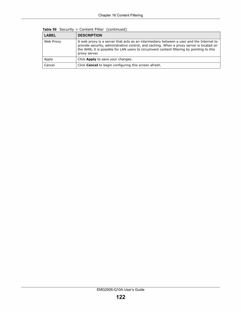
Chapter 16 Content Filtering
EMG2926-Q10A User’s Guide
122
Web Proxy A web proxy is a server that acts as an intermediary between a user and the Internet to provide security, administrative control, and caching. When a proxy server is located on the WAN, it is possible for LAN users to circumvent content filtering by pointing to this proxy server.
Apply Click Apply to save your changes.
Cancel Click Cancel to begin configuring this screen afresh.
Table 59 Security > Content Filter (continued)LABEL DESCRIPTION

EMG2926-Q10A User’s Guide
123
CHAPTER 17
Parental Controls
17.1 Overview
Parental controls allow you to block specific URLs. You can also define time periods and days during which the EMG2926-Q10A performs a parental control for a specific user.
17.2 Parental Control Screen
Use this screen to enable parental controls and view parental control rules and schedules.
Click Configuration > Security > Parental Control to open the following screen.
Figure 87 Security > Parental Control
The following table describes the fields on this screen.
Table 60 Security > Parental ControlLABEL DESCRIPTION
Parental Control
Select Enable to activate parental control.
Add new rules Click this if you want to configure a new parental control rule.
# This is the rule’s index number.
Status This indicates whether the rule is active or not.
A yellow lightbulb indicates that this rule is active. A grey lightbulb indicates that this rule is not active.
Rule Name This field shows the name of the rule.
Home Network User (MAC)
This field shows the MAC address of the LAN user’s computer to which the rule applies.
Internet Access Schedule
This field shows the day(s) and time on which parental control is enabled.

Chapter 17 Parental Controls
EMG2926-Q10A User’s Guide
124
17.2.1 Add/Edit a Parental Control Rule
Click Add new rules in the Parental Control screen to add a new rule or click the Edit icon next to an existing rule to edit it. Use this screen to configure a restricted access schedule and/or URL filtering settings to block the users on your network from accessing certain websites.
Network Service
This shows whether the network service is configured. If not, None will be shown.
Website Blocked
This shows whether the website block is configured. If not, None will be shown.
Modify Click the Edit icon to go to the screen where you can edit the rule.
Click the Delete icon to delete an existing rule.
Apply Click Apply to save your changes.
Cancel Click Cancel to restore your previously saved settings.
Table 60 Security > Parental Control (continued)LABEL DESCRIPTION

Chapter 17 Parental Controls
EMG2926-Q10A User’s Guide
125
Figure 88 Security > Parental Control: Add/Edit
The following table describes the fields on this screen.
Table 61 Security > Parental Control: Add/EditLABEL DESCRIPTION
General
Active Select the checkbox to activate this parental control rule.
Parental Control Profile Name
Enter a descriptive name for the rule.

Chapter 17 Parental Controls
EMG2926-Q10A User’s Guide
126
17.2.2 Add/Edit a Service
Click Add new service in the Parental Control > Add new rules/Edit screen to add a new entry or click the Edit icon next to an existing entry to edit it. Use this screen to configure a service rule.
Figure 89 Security > Parental Control > Add new rules/Edit > Add new service/Edit
Home Network User
Select the LAN user that you want to apply this rule to from the drop-down list box. If you select Custom, enter the LAN user’s MAC address. If you select All, the rule applies to all LAN users.
Internet Access Schedule
Day Select check boxes for the days you want the EMG2926-Q10A to perform the parental control rule.
Time Select begin and end times to define when the LAN user is allowed access.
Network Service
Network Service Setting
If you select Block, the EMG2926-Q10A will prohibit the users from using the services listed below.
If you select Allow, the EMG2926-Q10A will block all services except those listed below this field.
Add new service
Click this to show a screen in which you can add a new service rule. You can configure the Service Name, Protocol, and Port of the new rule.
# This shows the index number of the rule. Select the checkbox next to the rule to activate it.
Service Name This shows the name of the service.
Protocol:Port This shows the protocol and the port of the service.
Modify Click the Edit icon to go to the screen where you can edit the rule.
Click the Delete icon to delete an existing rule.
Block Site/URL Keyword
Click Add to show a screen to enter the website URL or URL keyword to which the EMG2926-Q10A blocks access. Click Delete to remove it.
Apply Click Apply to save your settings back to the EMG2926-Q10A.
Back Click Back to return to the previous screen.
Table 61 Security > Parental Control: Add/Edit (continued)LABEL DESCRIPTION

Chapter 17 Parental Controls
EMG2926-Q10A User’s Guide
127
The following table describes the fields on this screen.
17.3 Parental Monitor Screen
Use this screen to enable the parental monitor and view parental monitor rules and schedules.
Click Configuration > Security > Parental Monitor to open the following screen.
Figure 90 Security > Parental Monitor
The following table describes the fields on this screen.
Table 62 Security > Parental Control > Add new rules/Edit > Add new service/EditLABEL DESCRIPTION
Service Name Select the name of the service. Otherwise, select UserDefined and manually specify the service name, the protocol and the port of the service.
Protocol Select the transport layer protocol used for the service. Choices are TCP, UDP, or TCP/UDP.
If you have chosen a pre-defined service in the Service Name field, this field will not be configurable.
Port Enter the port of the service.
If you have chosen a pre-defined service in the Service Name field, this field will not be configurable.
Apply Click Apply to save your settings with the EMG2926-Q10A.
Back Click Back to return to the previous screen.
Table 63 Security > Parental MonitorLABEL DESCRIPTION
Parental Monitor
Select Enable to activate parental monitor.
Add new rules Click this if you want to configure a new parental monitor rule.
# This shows the index number of the rule.
Status This indicates whether the rule is active or not.
A yellow lightbulb indicates that the rule is active. A grey lightbulb indicates that the rule is not active.
Children Name This shows the name of the user to which the rule applies.
Device List This shows the name of the LAN user’s computer to which this rule applies.

Chapter 17 Parental Controls
EMG2926-Q10A User’s Guide
128
17.3.1 Add/Edit a Parental Monitor Rule
Click Add new rules in the Parental Monitor screen to add a new rule or click the Edit icon next to an existing rule to edit it. Use this screen to set a schedule and have the EMG2926-Q10A send a notification when the specified user connects to the EMG2926-Q10A at the scheduled time.
Figure 91 Security > Parental Monitor: Add/Edit
Monitor Schedule
This shows the day(s) and time periods when the parental monitor is enabled.
Notification This indicates whether the EMG2926-Q10A is programmed to send e-mail notifications when the user(s) is connected to the EMG2926-Q10A for Internet access during the time periods specified (Configured). If not, None will be shown.
Modify Click the Edit icon to go to the screen where you can edit the rule.
Click the Delete icon to delete an existing rule.
Apply Click Apply to save your changes.
Cancel Click Cancel to restore your previously saved settings.
Table 63 Security > Parental Monitor (continued)LABEL DESCRIPTION

Chapter 17 Parental Controls
EMG2926-Q10A User’s Guide
129
The following table describes the fields on this screen.
Table 64 Security > Parental Monitor: Add/EditLABEL DESCRIPTION
Monitored Devices
Active Select the checkbox to activate this parental monitor rule.
Children Name Enter a descriptive name for the user.
Device List The left text box lists the system name of the LAN/WLAN user device that is connected to the EMG2926-Q10A and has been assigned an IP address.
From the left text box, select the LAN/WLAN user device to which you want to apply this rule and click Add to move it to the right text box.
To remove a user device, select it from the right text box and click Delete.
Monitor Schedule
Day Select check boxes for the days on which you want the EMG2926-Q10A to send e-mail notifications if the user connects to the EMG2926-Q10A for Internet access.
Time Define the time period during which you want the EMG2926-Q10A to send e-mail notifications if the user connects to the EMG2926-Q10A for Internet access.
Notification The left text box lists the e-mail addresses you configured in the Management > Mail screen.
From the left text box, select the e-mail address to which you want to send e-mail notifications and click Add to move it to the right text box.
To remove an e-mail address, select it from the right text box and click Delete.
Apply Click Apply to save your settings back to the EMG2926-Q10A.
Back Click Back to return to the previous screen.

EMG2926-Q10A User’s Guide
130
CHAPTER 18
IPv6 Firewall
18.1 Overview
This chapter shows you how to enable and create IPv6 firewall rules to block unwanted IPv6 traffic.
18.2 IPv6 Firewall Screen
Click Configuration > Security > IPv6 Firewall. The Service screen appears as shown.
Figure 92 Configuration > Security > IPv6 Firewall

Chapter 18 IPv6 Firewall
EMG2926-Q10A User’s Guide
131
The following table describes the labels on this screen.
Table 65 Configuration > Security > IPv6 FirewallLABEL DESCRIPTION
Enable IPv6 Simple Security
Enable IPv6 Simple Security
Select this option to activate IPv6 simple security functions on the EMG2926-Q10A.
IPv6 simple security is a packet inspection mechanism. It checks the source IP address, destination IP address, IP protocol type, and connection state of network traffic and maintains a connection tracking table. IPv6 simple security allows any outgoing packets, and blocks all incoming packets except reply packets.
Apply Click Apply to save your settings.
ICMPv6 Internet Control Message Protocol for IPv6 (ICMPv6 or ICMP for IPv6) is defined in RFC 4443. ICMPv6 has a preceding Next Header value of 58, which is different from the value used to identify ICMP for IPv4. ICMPv6 is an integral part of IPv6. IPv6 nodes use ICMPv6 to report errors encountered in packet processing and to perform other diagnostic functions such as ping.
Respond to Ping on The EMG2926-Q10A will not respond to any incoming Ping requests when Disable is selected. Select LAN to reply to incoming LAN Ping requests. Select WAN to reply to incoming WAN Ping requests. Otherwise select LAN&WAN to reply to all incoming LAN and WAN Ping requests.
Apply Click Apply to save your settings.
Enable Firewall Rule
Enable Firewall Rule Select this check box to activate the firewall rules that you have defined (see Add Firewall Rule below).
Apply Click Apply to save your settings.
Add Firewall Rule
Service Name Enter a name that identifies or describes the firewall rule.
MAC Address Enter the MAC address of the computer to which the firewall rule applies.
Dest_IP_Address Enter the IPv6 address of the computer to which traffic for the application or service enters.
The EMG2926-Q10A applies the firewall rule to traffic destined for this computer.
Source_IP_Address Enter the IPv6 address of the computer that initializes traffic for the application or service.
The EMG2926-Q10A will apply the firewall rule to traffic initiating from this computer.
Protocol Select the protocol (TCP, UDP or ICMP) used to transport the packets for which you want the firewall rule to apply.
Dest Port Range Enter the port number/range of the destination that defines the traffic type. For example, TCP port 80 defines web traffic.
Source Port Range Enter the port number/range of the source that defines the traffic type. For example, TCP port 80 defines web traffic.
Add Rule Click Add Rule to save the firewall rule.
Firewall Rule
# This is your firewall rule number. The order of your rules is important, as rules are applied in order.
ServiceName This is a name that identifies or describes the firewall rule.
MACaddress This is the MAC address of the computer to which the firewall rule applies.
DestIP This is the IP address of the computer to which traffic for the application or service enters.
SourceIP This is the IP address of the computer where traffic for the application or service is initialized.

Chapter 18 IPv6 Firewall
EMG2926-Q10A User’s Guide
132
Protocol This is the protocol (TCP, UDP or ICMP) used to transport the packets for which you want to apply the firewall rule.
DestPortRange This is the port number/range of the destination that defines the traffic type. For example, TCP port 80 defines web traffic.
SourcePortRange This is the port number/range of the source that defines the traffic type. For example, TCP port 80 defines web traffic.
Action DROP - Traffic matching the conditions of the firewall rule is stopped.
Delete Click Delete to remove the firewall rule.
Cancel Click Cancel to restore your previously saved settings.
Table 65 Configuration > Security > IPv6 Firewall (continued)LABEL DESCRIPTION

EMG2926-Q10A User’s Guide
133
CHAPTER 19
StreamBoost Management
19.1 Overview
The EMG2926-Q10A supports StreamBoost, a new technology introduced by Qualcomm, to redistribute the EMG2926-Q10A traffic for the best possible performance in a home network.
Streamboost smart Quality of Service (QoS) technology detects traffic flow and applies traffic shaping policies automatically. It gives each device and application priority and provides the exact amount of bandwidth they need at any given time. This helps free up bandwidth for other applications or connected devices. If there is not enough bandwidth for optimal performance, Streamboost makes sure the application or device has the minimum acceptable bandwidth which is determined using StreamBoost’s cloud-based database.
Real-time application traffic (such as on-line games or communications) and video/audio streaming are given the highest priority. Downloads or torrent files are classified as best effort and placed lower than general network traffic (general browsing).
In the figure below, the StreamBoost-enabled EMG2926-Q10A differentiates incoming traffic flow going from the LAN device (A) or wireless device (B) to the Internet. It shapes traffic and gives priority and allocates bandwidth according to traffic types.
Figure 93 Example of StreamBoost Management
A
B

Chapter 19 StreamBoost Management
EMG2926-Q10A User’s Guide
134
19.2 Network Screen
Use this screen to view the current upstream and downstream transmission speeds between the EMG2926-Q10A and the Internet and/or between the EMG2926-Q10A and connected device(s) (represented by icons indicating the kind of network device), including those connecting wirelessly.
You can hover your cursor over a device icon to view details about the device, such as its name, IP address, MAC address, device type, and connection type.
Click Management > StreamBoost MGMT > Network to open the Network screen.
Figure 94 Management > StreamBoost Management > Network
19.3 Up Time Screen
Use this screen to view the top five traffic flows transmitting from/to the selected LAN device(s) in the past day, week or month.
Click Management > StreamBoost MGMT > Up Time to open the Up Time screen.
The y-axis shows the time period over which the traffic flow occurred. The x-axis shows the type of traffic flow.

Chapter 19 StreamBoost Management
EMG2926-Q10A User’s Guide
135
Figure 95 Management > StreamBoost Management > Up Time
19.4 Downloads Screen
Use this screen to view the type and percentage of most-downloaded traffic on the EMG2926-Q10A.
Click Management > StreamBoost MGMT > Downloads to open the Downloads screen.

Chapter 19 StreamBoost Management
EMG2926-Q10A User’s Guide
136
Figure 96 Management > StreamBoost Management > Downloads
Figure 97
19.5 PerDevice Screen
Use this screen to view the percentage of bandwidth used by the connected LAN/WLAN devices in the past month (Billing Period), within a specified period of time (Custom Period) or in the past three months (Quarterly). Click the Refresh buttonto update the information on this screen.
Click Management > StreamBoost MGMT > PerDevice to open the PerDevice screen.

Chapter 19 StreamBoost Management
EMG2926-Q10A User’s Guide
137
Figure 98 Management > StreamBoost Management > PerDevice
Click a device tab to open a screen displaying the selected device’s information and usage details. You can view the top flows on a monthly, daily, or hourly basis.
Figure 99 Management > StreamBoost Management > PerDevice

Chapter 19 StreamBoost Management
EMG2926-Q10A User’s Guide
138
19.6 PerFlow Screen
Use this screen to view the percentage of bandwidth used by a traffic flow in the past month (Billing Period), within a specified period of time (Custom Period) or in the past three months (Quarterly). Click the Flow Filter button to open a list where you can select the traffic flows you want to display. Click the Refresh buttonto update the information on this screen.
Click Management > StreamBoost MGMT > PerFlow to open the PerFlow screen.
Figure 100 Management > StreamBoost Management > PerFlow

EMG2926-Q10A User’s Guide
139
CHAPTER 20
Remote Management
20.1 Overview
This chapter provides information on the Remote Management screens.
Remote Management allows you to manage your EMG2926-Q10A from a remote location through the following interfaces:
• LAN and WAN
• LAN only
• WAN only
System Timeout
There is a default system management idle timeout of five minutes (three hundred seconds). The EMG2926-Q10A automatically logs you out if the management session remains idle for longer than this timeout period. The management session does not time out when a statistics screen is polling. You can change the timeout period in the Maintenance > General screen
20.2 WWW Screen
To change your EMG2926-Q10A’s remote management settings, click Management > Remote MGMT > WWW.

Chapter 20 Remote Management
EMG2926-Q10A User’s Guide
140
Figure 101 Management > Remote Management > WWW
The following table describes the labels on this screen.
20.3 SNMP
Simple Network Management Protocol is a protocol used for exchanging management information between network devices. Your EMG2926-Q10A supports SNMP agent functionality, which allows a manager station to manage and monitor the EMG2926-Q10A through the network. The EMG2926-Q10A supports SNMP version one (SNMPv1) and version two (SNMPv2c). The next figure illustrates an SNMP management operation:
Table 66 Management > Remote Management > WWWLABEL DESCRIPTION
Port You may change the server port number for a service if needed. However, you must use the same port number in order to use that service for remote management.
Access Status Select the interface(s) through which a computer may access the EMG2926-Q10A using this service.
Secured Client IP Address
Select All to allow all computers to access the EMG2926-Q10A.
Otherwise, check Selected and specify the IP address of the computer that can access the EMG2926-Q10A.
Apply Click Apply to save your customized settings.
Cancel Click Cancel to begin configuring this screen afresh.

Chapter 20 Remote Management
EMG2926-Q10A User’s Guide
141
Figure 102 SNMP Management Model
An SNMP managed network consists of two main types of component: agents and a manager.
An agent is a management software module that resides in a managed device (the EMG2926-Q10A). An agent translates the local management information from the managed device into a form compatible with SNMP. The manager is the console through which network administrators perform network management functions. It executes applications that control and monitor managed devices.
The managed devices contain object variables/managed objects that define each piece of information to be collected about a device. Examples of variables include number of packets received, node port status etc. A Management Information Base (MIB) is a collection of managed objects. SNMP allows a manager and agents to communicate for the purpose of accessing these objects.
SNMP itself is a simple request/response protocol based on the manager/agent model. The manager issues a request and the agent returns responses using the following protocol operations:
• Get - Allows the manager to retrieve an object variable from the agent.
• GetNext - Allows the manager to retrieve the next object variable from a table or list within an agent. In SNMPv1, when a manager wants to retrieve all elements of a table from an agent, it initiates a Get operation, followed by a series of GetNext operations.
• Set - Allows the manager to set values for object variables within an agent.
• Trap - Used by the agent to inform the manager of some events.
To change your EMG2926-Q10A’s SNMP settings, click Management > Remote MGMT > SNMP.

Chapter 20 Remote Management
EMG2926-Q10A User’s Guide
142
Figure 103 Management > Remote Management > SNMP
The following table describes the labels on this screen.
Table 67 Management > Remote Management > SNMPLABEL DESCRIPTION
SNMP Settings
Server Port You may change the server port number for a service if needed. However, you must use the same port number in order to use the service for remote management.
Server Access Select the interface(s) through which a computer may access the EMG2926-Q10A using the service.
Secured IP Select All to allow all computers to access the EMG2926-Q10A.
Otherwise, check Selected and specify the IP address of the computer that can access the EMG2926-Q10A.
SNMP Enable Select this to allow a manager station to manage and monitor the EMG2926-Q10A through the network via SNMP.
Get Community Enter the password for the incoming Get and GetNext requests from the management station. The default is public and allows all requests.
Set Community Enter the password for incoming Set requests from the management station. The default is public and allows all requests.
System Location Specify the geographic location of the EMG2926-Q10A.
System Contact Enter the name of the person in charge of the EMG2926-Q10A.
Trap Settings
Trap Enable Select this to have the EMG2926-Q10A send an SNMP trap to the specified IP address when it receives the event. Deselect to disable this feature.
Trap Manager IP Type the IP address of the SNMP manager to which your SNMP traps are sent.

Chapter 20 Remote Management
EMG2926-Q10A User’s Guide
143
20.4 Wake On LAN Screen
Wake On LAN (WoL) allows you to remotely turn on a device on the network, such as a computer, storage device or media server. To use this feature the remote hardware (for example the network adapter on a computer) must support Wake On LAN using the “Magic Packet” method.
You need to know the MAC address of the remote device. It may be on a label on the device.
Use this screen to remotely turn on a device on the network. Click Management > Remote MGMT > Wake On LAN to open the following screen.
Figure 104 Management > Remote Management > Wake On LAN
The following table describes the labels on this screen.
Trap Community Type the password sent with each trap to the SNMP manager. The default is public and allows all requests.
Apply Click Apply to save your customized settings.
Cancel Click Cancel to begin configuring this screen afresh.
Table 67 Management > Remote Management > SNMP (continued)LABEL DESCRIPTION
Table 68 Management > Remote Management > Wake On LANLABEL DESCRIPTION
Wake On LAN over WAN Settings
Enable WOL over WAN Select this option to have the EMG2926-Q10A forward a WoL “Magic Packet” to all devices on the LAN if the packet comes from the WAN or remote network and uses the port number specified in the Port field. A LAN device whose hardware supports Wake on LAN will then be turned on if it was turned off previously.
Port Type a port number from which a WoL packet will be forwarded to the LAN.
Wake On LAN
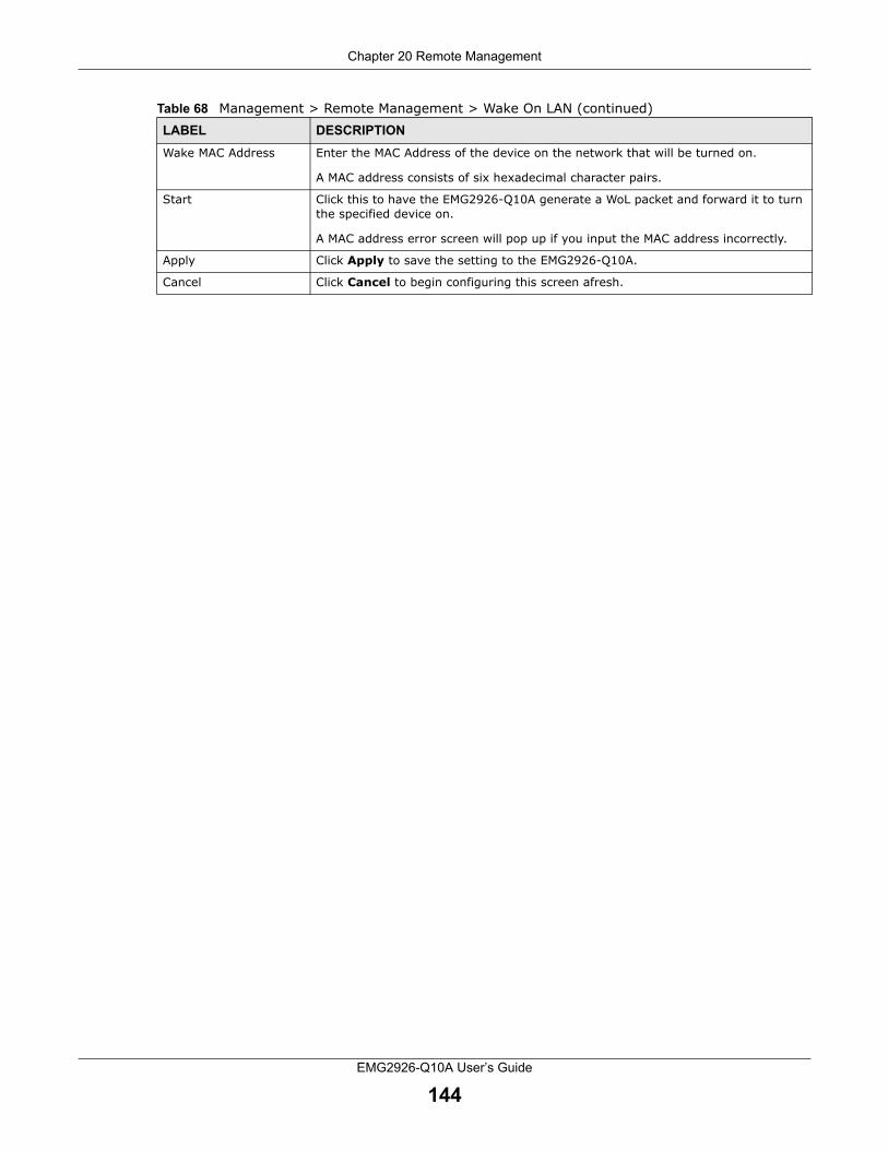
Chapter 20 Remote Management
EMG2926-Q10A User’s Guide
144
Wake MAC Address Enter the MAC Address of the device on the network that will be turned on.
A MAC address consists of six hexadecimal character pairs.
Start Click this to have the EMG2926-Q10A generate a WoL packet and forward it to turn the specified device on.
A MAC address error screen will pop up if you input the MAC address incorrectly.
Apply Click Apply to save the setting to the EMG2926-Q10A.
Cancel Click Cancel to begin configuring this screen afresh.
Table 68 Management > Remote Management > Wake On LAN (continued)LABEL DESCRIPTION

EMG2926-Q10A User’s Guide
145
CHAPTER 21
Universal Plug-and-Play (UPnP)
21.1 Overview
This chapter introduces the UPnP feature in the web configurator.
Universal Plug and Play (UPnP) is a distributed open networking standard that uses TCP/IP for simple peer-to-peer network connectivity between devices. A UPnP device can dynamically join a network, obtain an IP address, convey its capabilities and learn about other devices on the network. In turn, a device can leave a network smoothly and automatically when it is no longer in use.
UPnP hardware is identified as an icon in the Network Connections folder (Windows XP). Each UPnP-compatible device installed on your network will appear as a separate icon. Selecting a UPnP device icon will allow you to access the information and properties of that device.
UPnP Warnings
The automated nature of NAT traversal applications in establishing their own services and opening firewall ports may present network security issues. Network information and configuration may also be obtained and modified by users in some network environments.
When a UPnP device joins a network, it announces its presence with a multicast message. For security reasons, the EMG2926-Q10A allows multicast messages on the LAN only.
All UPnP-enabled devices can communicate freely with each other without additional configuration. Disable UPnP if this is not your intention.
21.2 UPnP Screen
Use this screen to enable UPnP on your EMG2926-Q10A.
Click Management > UPnP to display the following screen:
Figure 105 Management > UPnP
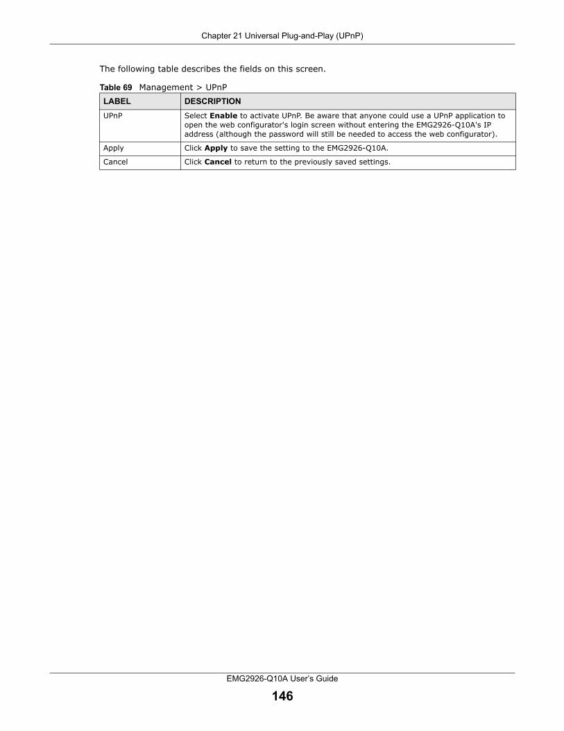
Chapter 21 Universal Plug-and-Play (UPnP)
EMG2926-Q10A User’s Guide
146
The following table describes the fields on this screen.
Table 69 Management > UPnPLABEL DESCRIPTION
UPnP Select Enable to activate UPnP. Be aware that anyone could use a UPnP application to open the web configurator's login screen without entering the EMG2926-Q10A's IP address (although the password will still be needed to access the web configurator).
Apply Click Apply to save the setting to the EMG2926-Q10A.
Cancel Click Cancel to return to the previously saved settings.

EMG2926-Q10A User’s Guide
147
CHAPTER 22
USB Media Sharing
22.1 Overview
This chapter describes how to configure media sharing settings on the EMG2926-Q10A.
Note: Reading and writing performance may be affected by amount of file-sharing traffic on your network, the type of connected USB device and the USB version (1.1 or 2.0).
Media Server
You can set up your EMG2926-Q10A to act as a media server to provide media (like video) to DLNA-compliant players, such as Windows Media Player, ZyXEL DMAs (Digital Media Adapters), Xboxes or PS3s. The IP addresses of the media server and clients must be in the same subnet.
The EMG2926-Q10A media server allows you to:
• Publish all folders for everyone to play media files in the USB storage device connected to the EMG2926-Q10A.
• Use hardware-based media clients like the DMA-2500 to play the files.
Note: Anyone on your network can play the media files in the published folders. No user names, passwords, or other forms of security are required.
The following figure is an overview of the EMG2926-Q10A’s media server feature. DLNA devices A and B can access and play files on a USB device (C) connected to the EMG2926-Q10A (D).
Figure 106 Media Server Overview
AB
C
D

Chapter 22 USB Media Sharing
EMG2926-Q10A User’s Guide
148
File-Sharing Server
You can also share files on a USB memory stick or hard drive connected to your EMG2926-Q10A with users on your network.
The following figure is an overview of the EMG2926-Q10A’s file-sharing server feature. Computers A and B can access files on a USB device (C) connected to the EMG2926-Q10A (D).
Figure 107 File Sharing Overview
22.2 DLNA Screen
Use this screen to have the EMG2926-Q10A act as a DLNA-compliant media server that lets DLNA-compliant media clients on your network access video, music, and photos from the EMG2926-Q10A (without having to copy them to another computer). Click Management > USB Media Sharing > DLNA.
A
B C
D

Chapter 22 USB Media Sharing
EMG2926-Q10A User’s Guide
149
Figure 108 Management > USB Media Sharing > DLNA
The following table describes the labels on this screen.
22.3 SAMBA Screen
Use this screen to set up file-sharing via the EMG2926-Q10A using Windows Explorer or the workgroup name. You can also configure the workgroup name and create file-sharing user accounts. Click Management > USB Media Sharing > SAMBA.
Table 70 Management > USB Media Sharing > DLNALABEL DESCRIPTION
Enable DLNA Select this to have the EMG2926-Q10A function as a DLNA-compliant media server.
USB1/2 Select the media type that you want to share on the USB device connected to the EMG2926-Q10A’s USB port.
Rescan Click this button to have the EMG2926-Q10A scan the media files on the connected USB device and index the file list again so that DLNA clients can find any new files.
Apply Click Apply to save your changes with the EMG2926-Q10A.
Cancel Click Cancel to begin configuring this screen afresh.

Chapter 22 USB Media Sharing
EMG2926-Q10A User’s Guide
150
Figure 109 Management > USB Media Sharing > SAMBA
The following table describes the labels on this screen.
Table 71 Management > USB Media Sharing > SAMBALABEL DESCRIPTION
Enable SAMBA Select this to enable file sharing through the EMG2926-Q10A using Windows Explorer or by accessing your work group.
Name Specify the name to identify the EMG2926-Q10A in a work group.
Work Group You can add the EMG2926-Q10A to an existing or a new work group on your network. Enter the name of the work group which your EMG2926-Q10A automatically joins. You can set the EMG2926-Q10A’s work group name to be exactly the same as the name of the work group to which your computer belongs.
Note: The EMG2926-Q10A will not be able to join the work group if your local area network settings restrict it from doing so. In this case, contact your network administrator.
Description Enter a description for the EMG2926-Q10A on the work group.
USB1/2 Specify the user’s access rights for the USB storage device connected to the EMG2926-Q10A’s USB port.
Read & Write - The user has read and write rights, meaning that the user can create and edit files on the connected USB device.
Read - The user has read rights only and can not create or edit files on the connected USB device.
User Accounts Before you can share files, you need a user account. Configure the following fields to set up a file-sharing account.
# This is the index number of the user account.

Chapter 22 USB Media Sharing
EMG2926-Q10A User’s Guide
151
22.4 FTP Screen
Use this screen to set up file sharing via the EMG2926-Q10A using FTP and create user accounts. Click Management > USB Media Sharing > FTP.
Figure 110 Management > USB Media Sharing > FTP
The following table describes the labels on this screen.
Enable This field displays whether a user account is activated or not. Select the check box to enable the account. Deselect the check box to disable the account.
User Name Enter the user name of a user that will be allowed to access the shared files. You can enter up to 20 characters (letters and numbers only).
Password Enter a password that the user can use to access the shared files. You can enter up to 20 characters (letters and numbers only). The password is case sensitive.
USB1/2 Select the USB port(s) on the EMG2926-Q10A. The configured user will only be able to access files on the USB device(s) connected to the selected USB port(s).
Apply Click Apply to save your changes to the EMG2926-Q10A.
Cancel Click Cancel to begin configuring this screen afresh.
Table 71 Management > USB Media Sharing > SAMBA (continued)LABEL DESCRIPTION
Table 72 Management > USB Media Sharing > FTPLABEL DESCRIPTION
Enable FTP Select this to enable the FTP server on the EMG2926-Q10A for file sharing using FTP.
Port You may change the server port number for FTP if needed. However, you must use the same port number in order to use that service for file sharing.
User Accounts Before you can share files, you need a user account. Configure the following fields to set up a file-sharing account.
# This is the index number of the user account.

Chapter 22 USB Media Sharing
EMG2926-Q10A User’s Guide
152
22.5 How to Access Your Shared Files From a Computer
You can use Windows Explorer or FTP to access the USB storage devices connected to the EMG2926-Q10A.
This example shows you how to use Microsoft Windows XP to browse your shared files. Refer to your operating system’s documentation for how to browse your file structure.
22.5.1 Use Windows Explorer to Share Files
You should have enabled file sharing and created a user account (e.g. Bob/1234) with read and write access to USB 1 in the USB Media Sharing > SAMBA screen.
Open Windows Explorer to access the connected USB device either by using Windows Explorer or by browsing to your work group.
Enable This field displays whether a user account is activated or not. Select the check box to enable the account. Deselect the check box to disable the account.
User Name Enter the user name of a user that will be allowed to access the shared files. You can enter up to 20 characters (letters and numbers only).
Password Enter a password that the user can use to access the shared files. You can enter up to 20 characters (letters and numbers only). The password is case sensitive.
USB1/2 Specify the user’s access rights to the USB storage device connected to the EMG2926-Q10A’s USB port.
Read & Write - The user has read and write rights, meaning that the user can create and edit files on the connected USB device.
Read - The user has read rights only and can not create or edit files on the connected USB device.
None - The user cannot access files on the USB device(s) connected to the USB port.
Upstream Bandwidth
Enter the maximum bandwidth (in Kbps) allowed for incoming FTP traffic.
Downstream Bandwidth
Enter the maximum bandwidth (in Kbps) allowed for outgoing FTP traffic.
Apply Click Apply to save your changes to the EMG2926-Q10A.
Cancel Click Cancel to begin configuring this screen afresh.
Table 72 Management > USB Media Sharing > FTP (continued)LABEL DESCRIPTION

Chapter 22 USB Media Sharing
EMG2926-Q10A User’s Guide
153
1 In the Windows Explorer Address bar, type a double backslash “\\” followed by the EMG2926-Q10A’s IP address (the default IP address of the EMG2926-Q10A in router mode is 192.168.0.1) and press [ENTER]. A password authentication screen will appear. Enter the user name and password (Bob and 1234 in this example) and click OK.
Note: Once you log into the shared folder via your EMG2926-Q10A, you will not have to log in again unless you restart your computer.

Chapter 22 USB Media Sharing
EMG2926-Q10A User’s Guide
154
2 You can also use the work group name to access files by browsing the work group folder using the folder tree on the left side of the screen. It is located under My Network Places. In this example, the work group name is the default “Workgroup”.
22.5.2 Use FTP to Share Files
You can use FTP to access the USB storage devices connected to the EMG2926-Q10A. In this example, we use the web browser to share files via FTP from the LAN. The way you log in to the FTP server (on the EMG2926-Q10A) and the screen that appears will vary depending on your FTP client. See your FTP client documentation for more information.
You should have enabled file sharing and created a user account (Bob/1234 for example) with read and write access to USB 1 in the USB Media Sharing > FTP screen.
1 In your web browser’s address or URL bar type “ftp://” followed by the IP address of the EMG2926-Q10A (the default LAN IP address of the EMG2926-Q10A in router mode is 192.168.0.1) and click Go or press [ENTER].

Chapter 22 USB Media Sharing
EMG2926-Q10A User’s Guide
155
2 A password authentication screen will appear. Enter the user name and password you configured on the USB Media Sharing > FTP screen and click Log In.
3 The screen will change and display the folder for the USB storage device connected to your EMG2926-Q10A. Double-click the folder to display its contents.

EMG2926-Q10A User’s Guide
156
CHAPTER 23
Port Configuration
23.1 Overview
The EMG2926-Q10A has 1000Base-T auto-negotiating Ethernet ports. In 10/100/1000 Mbps Gigabit Ethernet, the speed can be 10 Mbps, 100 Mbps or 1000 Mbps. The duplex mode can be both half or full duplex. An auto-negotiating port can detect and adjust to the optimum Ethernet speed (10/100/1000 Mbps) and duplex mode (full duplex or half duplex) for the connected device.
23.2 Port Configuration Screen
Use this screen to configure the EMG2926-Q10A port speed and duplex settings. Click Configuration > Management > Port Configuration.
Figure 111 Management > Port Configuration
The following table describes the labels on this screen.
Table 73 Management > Port ConfigurationLABEL DESCRIPTION
WAN/LAN1~4 This field displays the EMG2926-Q10A’s Ethernet port.
Speed Select the speed of the Ethernet connection on this port. The choices are Auto, 1000, 100 and 10.
Selecting Auto (auto-negotiation) allows one port to negotiate with a peer port automatically to obtain the connection speed that both ends support. If the peer port does not support auto-negotiation, or if it turns off this feature, the EMG2926-Q10A determines the connection speed by detecting the signal on the cable and using half duplex mode.

Chapter 23 Port Configuration
EMG2926-Q10A User’s Guide
157
Duplex Select the duplex mode of the Ethernet connection on this port. The choices are Auto, Full and Half.
Selecting Auto (auto-negotiation) allows one port to negotiate with a peer port automatically to obtain the duplex mode that both ends support. If the peer port does not support auto-negotiation or turns off this feature, the EMG2926-Q10A will determine the connection speed by detecting the signal on the cable and using half duplex mode.
Apply Click Apply to save your changes with the EMG2926-Q10A.
Cancel Click Cancel to begin configuring this screen afresh.
Table 73 Management > Port Configuration (continued)LABEL DESCRIPTION

EMG2926-Q10A User’s Guide
158
CHAPTER 24
USB Print Server
24.1 Overview
The EMG2926-Q10A allows you to share a USB printer on your LAN. You can do this by connecting a USB printer to one of the USB ports on the EMG2926-Q10A and then allowing the computers connected to your network to communicate with the print server (EMG2926-Q10A) using the Internet Printing Protocol.
Figure 112 Sharing a USB Printer
To configure the print server:
• Your EMG2926-Q10A must be connected to your computer and to any other devices on your network. The USB printer must be connected to your EMG2926-Q10A.
• The computers on your network must have the printer software already installed before they can use the printer. Follow your printer manufacturers instructions on how to install the printer software on your computer.
Note: Your printer’s installation instructions may ask that you connect the printer to your computer. Connect your printer to the EMG2926-Q10A instead.
24.2 Print Server Screen
Use this screen to enable the print server function on the EMG2926-Q10A and to confirm that the EMG2926-Q10A and the USB printer are able to communicate successfully. Click Management > USB Print Server.

Chapter 24 USB Print Server
EMG2926-Q10A User’s Guide
159
Figure 113 Management > USB Print Server
The following table describes the labels on this screen.
Table 74 Management > USB Print ServerLABEL DESCRIPTION
Print Server Select Enable to have the EMG2926-Q10A act as a print server. Otherwise, select Disable.
Printer Name This displays the descriptive name of the associated printer for its recognition on the print server network.
This name is displayed on a computer on the print server network when a print job is executed.
Apply Click Apply to save your changes to the EMG2926-Q10A.
Cancel Click Cancel to begin configuring this screen afresh.

EMG2926-Q10A User’s Guide
160
CHAPTER 25
25.1 Overview
A mail server is an application or a computer that runs an application to receive, forward and deliver email messages.
To have the EMG2926-Q10A send reports, logs or notifications via email, you must specify an email server and the email addresses of the sender and receiver.
25.2 My Mail Screen
Use this screen to configure the mail server information on the EMG2926-Q10A. Click Management > Mail.
Figure 114 Management > Mail

Chapter 25 Mail
EMG2926-Q10A User’s Guide
161
The following table describes the labels on this screen.
Table 75 Management > MailLABEL DESCRIPTION
Mail Server Select Default to use the pre-defined mail server to send or receive mail messages.
Select Custom to specify a different mail server.
Mail Server Address If you select Default in the Mail Server field, this will show the pre-defined mail server address and will not be configurable.
If you select Custom in the Mail Server field, enter the server name or the IP address of the mail server for the e-mail address specified in the Account Email Address field
Mail Server Port Specify a mail server port. Enter port 25 if you are using a mail server from your ISP. Enter port 587 if you are using your own mail server that is not on your ISP's network.
Authentication Username
Enter the user name (up to 32 characters). This is usually the user name of the mail account you specified in the Account Email Address field.
Authentication Password
Enter the password associated with the user name above.
Account Email Address
Enter the email address that you want to be in the from/sender line of the email notification that the EMG2926-Q10A sends.
Email Enter the email address to which outgoing email is delivered and click Add to add it to the Send To list.
# This is the index number of an email address in the list.
Email This is the email address to which outgoing email is delivered.
Modify Click the Edit icon to open a screen where you can change the email address.
Click the Delete icon to remove an existing entry.
Apply Click Apply to save your changes to the EMG2926-Q10A.
Cancel Click Cancel to begin configuring this screen afresh.

EMG2926-Q10A User’s Guide
162
CHAPTER 26
Maintenance
26.1 Overview
This chapter provides information on the Maintenance screens.
26.2 General Screen
Use this screen to set the management session timeout period. Click Maintenance > General. The following screen will appear.
Figure 115 Maintenance > General
The following table describes the labels on this screen.
26.3 Account Screen
It is strongly recommended that you change the password of the user account.
Table 76 Maintenance > GeneralLABEL DESCRIPTION
System Name System Name is a unique name to identify the EMG2926-Q10A in an Ethernet network.
Domain Name Enter the domain name you wish to give to the EMG2926-Q10A.
Administrator Inactivity Timer
Type how many minutes a management session can be left idle before the session times out. The default is 5 minutes. After the session times out you will have to log in with your password again. Very long idle timeouts may have security risks. A value of "0" means a management session never times out, no matter how long it has been left idle (not recommended).
Apply Click Apply to save your changes to the EMG2926-Q10A.
Cancel Click Cancel to begin configuring this screen afresh.

Chapter 26 Maintenance
EMG2926-Q10A User’s Guide
163
If you forget your login account password (or IP address), you will need to reset the device. See Section 26.5 on page 165 for details.
Click Maintenance > Account. The screen will appear as shown.
Figure 116 Maintenance > Account
The following table describes the labels on this screen.
26.3.1 Edit a User’s Account
Use this screen to edit a user’s account. Click the Edit icon next to the user account you want to edit. The Account Setup screen displays as shown.
Figure 117 Maintenance > Account > Edit
Table 77 Maintenance > AccountLABEL DESCRIPTION
# This the index number of the entry.
User Name This field displays the user name.
Group This field displays the user’s login account type.
Different login account types have different privilege levels. The web configurator screens and privileges will vary depending on which account type you use to log in.
Modify Click the Edit icon to go to the screen where you can edit the account.

Chapter 26 Maintenance
EMG2926-Q10A User’s Guide
164
The following table describes the labels on this screen.
26.4 Configuration Backup/Restore Screen
Backup configuration allows you to back up (save) the EMG2926-Q10A’s current configuration to a file on your computer. Once your EMG2926-Q10A is configured and functioning properly, it is highly recommended that you back up your configuration file before making configuration changes. The backup configuration file will be useful in case you need to return to your previous settings.
Restoring configuration allows you to upload a new or previously saved configuration file from your computer to your EMG2926-Q10A.
Click Maintenance > Backup/Restore. Information related to factory defaults, backup configuration, and restoring configuration will appear as shown below.
Table 78 Maintenance > Account > EditLABEL DESCRIPTION
Username Enter a descriptive name for the user account. The user name can be made up of up to 15 alphanumeric characters (0-9, A-Z, a-z, -, _) with no spaces. If advanced account security is enabled, the user names must have a minimum of six characters and include both letters and numbers.
Old Password Type the default password or the existing password you use to access the system in this field.
New Password Type your new system password (up to 30 characters). Note that as you type a password, the screen displays an asterisk (*) for each character you type.
Retype to Confirm Retype the new password in this field.
Group This is the user’s account type.
The web configurator screens and privileges vary depending on which account type you use to log in. Administrator accounts can configure the EMG2926-Q10A and upgrade firmware while User accounts cannot do firmware upgrading.
Apply Click Apply to save your changes to the EMG2926-Q10A.
Cancel Click Cancel to begin configuring this screen afresh.

Chapter 26 Maintenance
EMG2926-Q10A User’s Guide
165
Figure 118 Maintenance > Backup/Restore
The following table describes the labels on this screen.
Note: If you uploaded the default configuration file, you may need to change the IP address of your computer to be in the same subnet as that of the default EMG2926-Q10A IP address (192.168.0.1).
26.5 Restart Screen
System restart allows you to reboot the EMG2926-Q10A without turning the power off.
Table 79 Maintenance > Backup/RestoreLABEL DESCRIPTION
Backup Click Backup to save the EMG2926-Q10A’s current configuration to your computer.
File Path Type in the location of the file you want to upload in this field or click Browse... to find it.
Choose File Click Choose File to find the file you want to upload. Remember that you must decompress compressed (.ZIP) files before you can upload them.
Upload Click Upload to begin the upload process.
Note: Do not turn off the EMG2926-Q10A while configuration file upload is in progress.
After you see a “configuration upload successful” screen, you must then wait one minute before logging in to the EMG2926-Q10A again. The EMG2926-Q10A will automatically restart at this time, causing a temporary network disconnect.
If you see an error screen, click Back to return to the Backup/Restore screen.
Reset Pressing the Reset button in this section clears all user-entered configuration information and returns the EMG2926-Q10A to its factory defaults.
You can also press the RESET button on the rear panel to reset the factory defaults of your EMG2926-Q10A. Refer to the chapter about introducing the Web Configurator for more information on the RESET button.

Chapter 26 Maintenance
EMG2926-Q10A User’s Guide
166
Click Maintenance > Restart to open the following screen.
Figure 119 Maintenance > Restart
Click Restart to have the EMG2926-Q10A reboot. This does not affect the EMG2926-Q10A's configuration.
26.6 System Operating Mode Overview
The Sys OP Mode (System Operating Mode) function lets you configure your EMG2926-Q10A as a router or access point. You can choose between Router Mode, and Access Point Mode depending on your network topology and the features you require from your device.
The following describes the device modes available on your EMG2926-Q10A.
Router
A router connects your local network with another network, such as the Internet. The router has two IP addresses: the LAN IP address and the WAN IP address.
Figure 120 LAN and WAN IP Addresses in Router Mode
Access Point
An access point enables all Ethernet ports to be bridged together and to be in the same subnet. To connect to the Internet, another device (such as a router) is required.

Chapter 26 Maintenance
EMG2926-Q10A User’s Guide
167
Figure 121 Access Point Mode
26.7 Sys OP Mode Screen
Use this screen to select how you want to use your EMG2926-Q10A.
Figure 122 Maintenance > Sys OP Mode
The following table describes the labels on the General screen.
Table 80 Maintenance > Sys OP ModeLABEL DESCRIPTION
Configuration Mode
Router Mode Select Router Mode if your device routes traffic between a local network and another network such as the Internet. This mode offers services such as a firewall or bandwidth management.
You can configure the IP address settings on your WAN port. Contact your ISP or system administrator for more information on appropriate settings.

Chapter 26 Maintenance
EMG2926-Q10A User’s Guide
168
Note: If you select the incorrect system operation Mode you may not be able to connect to the Internet.
26.8 Language Screen
Use this screen to change the language for the Web Configurator.
Select the language you prefer and click Apply. The Web Configurator language changes after a while without restarting the EMG2926-Q10A. At the time of writing, you can only select English or Francais.
Figure 123 Maintenance > Language
26.9 Diagnostic Screen
The Diagnostic screens display information to help you identify problems with the EMG2926-Q10A.
26.9.1 Ping Screen
Use this screen to ping an IP address. Click Maintenance > Diagnostic > Ping to open the following screen.
Access Point Mode Select Access Point Mode if your device bridges traffic between clients on the same network.
• In Access Point Mode, all Ethernet ports have the same IP address. • All ports on the rear panel of the device are LAN ports, including the port
labeled WAN. There is no WAN port.• The DHCP server on your device is disabled. • Router functions (such as NAT, bandwidth management, remote management,
firewall, etc.) are not available when the EMG2926-Q10A is in Access Point Mode.
• The IP address of the device on the local network is set to 192.168.0.2.
Apply Click Apply to save your settings.
Cancel Click Cancel to return your settings to the default (Router).
Table 80 Maintenance > Sys OP Mode (continued)LABEL DESCRIPTION

Chapter 26 Maintenance
EMG2926-Q10A User’s Guide
169
Figure 124 Maintenance > Diagnostic > Ping
The following table describes the fields on this screen.
26.9.2 TraceRoute Screen
Use this screen to trace the route packets take to a host. Click Maintenance > Diagnostic > TraceRoute to open the following screen.
Figure 125 Maintenance > Diagnostic > TraceRoute
Table 81 Maintenance > Diagnostic > Ping LABEL DESCRIPTION
Type the URL or IP address of a computer to which you want to perform Ping in order to test a connection.
IPv4_Ping
IPv6_Ping
Click the button to ping the IP address that you entered.

Chapter 26 Maintenance
EMG2926-Q10A User’s Guide
170
The following table describes the fields on this screen.
26.9.3 Nslookup Screen
Use this screen to perform an nslookup (name server lookup). Nslookup queries the DNS to resolve an IP address into a host name and vice-versa. Click Maintenance > Diagnostic > Nslookup to open the following screen.
Figure 126 Maintenance > Diagnostic > Nslookup
The following table describes the fields on this screen.
26.9.4 SpeedTest Screen
Use this screen to test your Internet connection. Click Maintenance > Diagnostic > SpeedTest to open the following screen.
Table 82 Maintenance > Diagnostic > TraceRoute LABEL DESCRIPTION
Type the URL or IP address of a computer for which you want to perform traceroute in order to test a connection.
IPv4_TraceRoute
IPv6_TraceRoute
Click this button to perform the traceroute function. This determines the path a packet takes to the specified computer.
Table 83 Maintenance > Diagnostic > NslookupLABEL DESCRIPTION
FQDN_IP Type a domain name or IP address in this field for the name server lookup.
ServerIP Enter the IP address of the server the EMG2926-Q10A uses to translate the specified domain name or IP address.
Nslookup Click this button to perform a DNS lookup on the IP address or domain name you entered.

Chapter 26 Maintenance
EMG2926-Q10A User’s Guide
171
Figure 127 Maintenance > Diagnostic > SpeedTest
The following table describes the fields on this screen.
Table 84 Maintenance > Diagnostic > SpeedTestLABEL DESCRIPTION
Latency This field displays the period of delay (in milliseconds) on the connection.
Download Speed This field displays the current downstream transmission rate.
Upload Speed This field displays the current upstream transmission rate.
Begin Test Click this button to perform a speed-test immediately.

EMG2926-Q10A User’s Guide
172
CHAPTER 27
Troubleshooting
27.1 Overview
This chapter offers some suggestions for solving problems you might encounter. The potential problems are divided into the following categories.
• Power, Hardware Connections, and LEDs
• EMG2926-Q10A Access and Login
• Internet Access
• Resetting the EMG2926-Q10A to Its Factory Defaults
• Wireless Connections
• USB Device Problems
27.2 Power, Hardware Connections, and LEDs
The EMG2926-Q10A does not turn on. None of the LEDs turn on.
1 Make sure you are using the power adaptor or cord included with the EMG2926-Q10A.
2 Make sure the power adaptor or cord is connected to the EMG2926-Q10A and plugged in to an appropriate power source. Make sure the power source is turned on.
3 Disconnect and re-connect the power adaptor or cord to the EMG2926-Q10A.
4 If the problem continues, contact the vendor.
One of the LEDs does not behave as expected.
1 Make sure you understand the normal behavior of the LED. See Section 1.7 on page 14.
2 Check the hardware connections. See the Quick Start Guide.
3 Inspect your cables for damage. Contact the vendor to replace any damaged cables.
4 Disconnect and re-connect the power adaptor to the EMG2926-Q10A.

Chapter 27 Troubleshooting
EMG2926-Q10A User’s Guide
173
5 If the problem continues, contact the vendor.
27.3 EMG2926-Q10A Access and Login
I don’t know the IP address of my EMG2926-Q10A.
1 The default IP address of the EMG2926-Q10A in Router Mode is 192.168.0.1. The default IP address of the EMG2926-Q10A in Access Point Mode is 192.168.0.2.
2 If you changed the IP address and have forgotten it, you may be able to get the IP address of the EMG2926-Q10A in Router Mode by looking up the IP address of the default gateway for your computer. To do this in most Windows computers, click Start > Run, enter cmd, and then enter ipconfig. The IP address of the Default Gateway might be the IP address of the EMG2926-Q10A (depending on the network), so enter this IP address in your Internet browser.
3 If your EMG2926-Q10A in Access Point Mode is a DHCP client, you can obtain your IP address from the DHCP server. This information is only available from the DHCP server that allocates IP addresses on your network. Find this information directly on the DHCP server, or contact your system administrator for more information.
4 Reset your EMG2926-Q10A to change all settings back to their defaults. This means your current settings will be lost. See Section 27.5 on page 176 in Troubleshooting for information on resetting your EMG2926-Q10A.
I forgot the password.
1 The default password is an empty string.
2 If this does not work, you will have to reset the device to its factory defaults. See Section 27.5 on page 176.
I cannot see or access the Login screen in the Web Configurator.
1 Make sure you are using the correct IP address.
• The default IP address of the EMG2926-Q10A in Router Mode is 192.168.0.1. The default IP address of the EMG2926-Q10A in Access Point Mode is 192.168.0.2.
• If you changed the IP address (Section 10.2 on page 97), use the new IP address.
• If you changed the IP address and have forgotten it, see the troubleshooting suggestions for I don’t know the IP address of my EMG2926-Q10A.

Chapter 27 Troubleshooting
EMG2926-Q10A User’s Guide
174
2 Check the hardware connections, and make sure the LEDs are behaving as expected. See the Quick Start Guide.
3 Make sure your Internet browser does not block pop-up windows and has JavaScript and Java enabled.
4 Make sure your computer is in the same subnet as the EMG2926-Q10A. Skip this step if you know that there are routers between your computer and the EMG2926-Q10A.
• If there is a DHCP server on your network, make sure your computer is using a dynamic IP address. See Section 10.2 on page 97.
• If there is no DHCP server on your network, make sure your computer’s IP address is in the same subnet as the EMG2926-Q10A. See Section 10.2 on page 97.
5 Reset the device to its factory defaults, and try to access the EMG2926-Q10A with the default IP address. See Section 1.5 on page 13.
6 If the problem continues, contact the network administrator or vendor, or try one of the advanced suggestions below.
Advanced Suggestions
• Try to access the EMG2926-Q10A using another service, such as Telnet. If you can access the EMG2926-Q10A, check the remote management settings and firewall rules to find out why the EMG2926-Q10A does not respond to HTTP.
• If your computer is connected to the WAN port or is connected wirelessly, use a computer that is connected to a LAN/ETHERNET port.
I can see the Login screen, but I cannot log in to the EMG2926-Q10A.
1 Make sure you have left the password field blank. The default password is an empty string.
2 This can happen when you fail to log out properly from your last session. Try logging in again after 5 minutes.
3 Disconnect and re-connect the power adaptor or cord to the EMG2926-Q10A.
4 If this does not work, you have to reset the device to its factory defaults. See Section 27.5 on page 176.
27.4 Internet Access
I cannot access the Internet.
1 Check the hardware connections, and make sure the LEDs are behaving as expected. See the Quick Start Guide.

Chapter 27 Troubleshooting
EMG2926-Q10A User’s Guide
175
2 Go to Maintenance > Sys OP Mode. Check your System Operation Mode setting.
• If the EMG2926-Q10A is in Router Mode, make sure that the WAN port is connected to a broadband modem or router with Internet access. Your computer and the EMG2926-Q10A should be in the same subnet.
• If the EMG2926-Q10A is in Access Point Mode, make sure that the WAN port is connected to a broadband modem or router with Internet access and that your computer is set to obtain a dynamic IP address.
3 If the EMG2926-Q10A is in Router Mode, make sure you entered your ISP account information correctly in the wizard or the WAN screen. These fields are case-sensitive, so make sure [Caps Lock] is not on.
4 If you are trying to access the Internet wirelessly, make sure the wireless settings in the wireless client are the same as the settings in the AP.
5 Disconnect all the cables from your device, and follow the directions in the Quick Start Guide again.
6 If the problem continues, contact your ISP.
I cannot access the Internet anymore. I had access to the Internet (with the EMG2926-Q10A), but my Internet connection is not available anymore.
1 Check the hardware connections, and make sure the LEDs are behaving as expected. See the Quick Start Guide and Section 1.7 on page 14.
2 Reboot the EMG2926-Q10A.
3 If the problem continues, contact your ISP.
The Internet connection is slow or intermittent.
1 There might be a lot of traffic on the network. Look at the LEDs, and check Section 1.7 on page 14. If the EMG2926-Q10A is sending or receiving a lot of information, try closing some programs that use the Internet, especially peer-to-peer applications.
2 Check the signal strength. If the signal strength is low, try moving the EMG2926-Q10A closer to the AP if possible, and look around to see if there are any devices that might be interfering with the wireless network (for example, microwaves, other wireless networks, and so on).
3 Reboot the EMG2926-Q10A.
4 If the problem continues, contact the network administrator or vendor, or try the advanced suggestion below.
Advanced Suggestion
• Check the settings for QoS. If it is disabled, you might consider activating it.

Chapter 27 Troubleshooting
EMG2926-Q10A User’s Guide
176
27.5 Resetting the EMG2926-Q10A to Its Factory Defaults
If you reset the EMG2926-Q10A, you will lose all of the changes you have made. The EMG2926-Q10A will reload its default settings and use a blank password. You will have to make all of your changes again.
You will lose all of your changes when you push the RESET button.
To reset the EMG2926-Q10A:
1 Make sure the power LED is on.
2 Press the RESET button for one to four seconds to restart/reboot the EMG2926-Q10A.
3 Press the RESET button for longer than five seconds to set the EMG2926-Q10A back to its factory-default configurations.
If the EMG2926-Q10A restarts automatically, wait for the EMG2926-Q10A to finish restarting, then log in to the Web Configurator. The default password is an empty string.
If the EMG2926-Q10A does not restart automatically, disconnect and reconnect the EMG2926-Q10A’s power. Then, follow the directions above again.
27.6 Wireless Connections
I cannot access the EMG2926-Q10A or ping any computer from the WLAN.
1 Make sure the wireless LAN is enabled on the EMG2926-Q10A.
2 Make sure the wireless adapter on your computer is working properly.
3 Make sure the wireless adapter installed on your computer is IEEE 802.11 compatible and supports the same wireless standard as the EMG2926-Q10A.
4 Make sure your computer (with a wireless adapter installed) is within the transmission range of the EMG2926-Q10A.
5 Check that both the EMG2926-Q10A and the wireless adapter on your computer are using the same wireless and wireless security settings.
6 Make sure traffic between the WLAN and the LAN is not blocked by the firewall on the EMG2926-Q10A.
7 Make sure you allow remote access to the EMG2926-Q10A through the WLAN interface. Check your remote management settings.

Chapter 27 Troubleshooting
EMG2926-Q10A User’s Guide
177
• See the chapter on Wireless LAN in the User’s Guide for more information.
I set up URL keyword blocking, but I can still access a website that should be blocked.
Make sure that you enable parental control in the Parental Control screen, set up rules and turn them on. Additionally, make sure that the keywords that you type are listed in the rule’s Keyword List.
I switched to AP mode and cannot access the Web Configurator.
When you change from router mode to AP mode, your computer must have an IP address in the range between “192.168.0.3” and “192.168.0.254”.
What factors may cause an intermittent or unstable wireless connection? How can I solve this problem?
The following factors may cause interference:
• Obstacles: Walls, ceilings, furniture, and so on.
• Building Materials: Metal doors, aluminum studs.
• Electrical devices: Microwaves, monitors, electric motors, cordless phones, and other wireless devices.
To optimize the speed and quality of your wireless connection, you can:
• Move your wireless device closer to the AP if the signal strength is low.
• Reduce wireless interference that may be caused by other wireless networks or surrounding wireless electronics such as cordless phones.
• Place the AP in a location witha minimum of obstacles (such as walls and ceilings) between it and the wireless client.
• Reduce the number of wireless clients connecting to the same AP simultaneously, or add additional APs if necessary.
• Try closing some programs that use the Internet, especially peer-to-peer applications. If the wireless client is sending or receiving a lot of information, it may have too many programs open that use the Internet.
• Position the antennas for best reception. If the AP is placed on a table or floor, point the antennas upwards. If the AP is placed at a high position, point the antennas downwards. Try pointing the antennas in different directions and check which provides the strongest signal to the wireless clients.
Chapter 27 Troubleshooting
EMG2926-Q10A User’s Guide
178
27.7 USB Device Problems
I cannot access or see a USB device that is connected to the EMG2926-Q10A.
1 Disconnect the problematic USB device, then reconnect it to the EMG2926-Q10A.
2 Ensure that the USB device has power.
3 Check your cable connections.
4 Restart the EMG2926-Q10A by disconnecting the power and then reconnecting it.
5 If the USB device requires a special driver, install the driver from the installation disc that came with the device. After driver installation, reconnect the USB device to the EMG2926-Q10A and try to connect to it again with your computer.
6 If the problem persists, contact your vendor.
What kind of USB devices does the EMG2926-Q10A support?
1 It is strongly recommended to use version 2.0 or lower USB storage devices (such as memory sticks and USB hard drives) and/or other USB devices. Other USB products are not guaranteed to function properly with the EMG2926-Q10A.