Embed Size (px)
Citation preview

1070-Series
EmergencyRestorationSystem
ERS
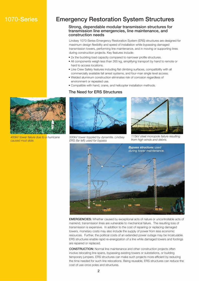
Bypass structure: used during tower maintenance.
Lindsey 1070‐Series Emergency Restoration System (ERS) structures are designed for maximum design flexibility and speed of installation while bypassing damaged transmission towers, performing line maintenance, and in moving or supporting lines during construction projects. Key features include:
1070‐Series Emergency Restoration System Structures
EMERGENCIES: Whether caused by exceptional acts of nature or uncontrollable acts of mankind, transmission lines are vulnerable to mechanical failure. The resulting loss of transmission is expensive. In addition to the cost of repairing or replacing damaged towers, monetary costs may also include the supply of power from less economic resources. Further, the political costs of an extended power outage may be incalculable. ERS structures enable rapid re‐energization of a line while damaged towers and footings are repaired or replaced.
CONSTRUCTION: Normal line maintenance and other construction projects often involve relocating line spans, bypassing existing towers or substations, or building temporary jumpers. ERS structures can make such projects more efficient by reducing the time needed for such line relocations. Being reusable, ERS structures can reduce the cost of use‐once poles and structures.
• 2x the buckling load capacity compared to narrower profile structures.• All components weigh less than 265 kg, simplifying transport by hand to remote or hard to access locations.• Line Crew Safety features including flat climbing surfaces, compatibility with all commercially available fall arrest systems, and four‐man single level access. • Welded aluminum construction eliminates risk of corrosion regardless of environment or repeated use.• Compatible with hand, crane, and helicopter installation methods.
222
Strong, dependable modular transmission structures for transmission line emergencies, line maintenance, andconstruction needs
The Need for ERS Structures
400kV tower failure due to a hurricane caused mud slide.
500kV tower toppled by dynamite. Lindsey ERS (far left) used for bypass
115kV steel monopole failure resulting from high winds and debris.

Standards Compliances
Performance
Installation
Safety
Relative buckling strength 150% 100% 130% 300%All extruded or plate aluminum Yes Yes Yes Yesconstruction
All system components, weigh <100kgs
Manual, crane or helicopter installation Yes Yes Yes Yes
Column Width (mm) 610 575 575 750
Maximum number of workmen at one level 4 4 4 4
Accepts all commercially available fall Yes Yes Yes Yesarrests systemsFlat climbing surfaces Yes Yes Yes Yes
Column sections pack into 20’ containers No Yes Yes YesOther system components pack into 20’ Yes Yes Yes Yescontainers
Packaging
1070 600L 600H 800
ERS Series
Design and Testing Compliant to IEEE Yes Yes Yes YesStd. 1070 and IEC-60652Dimentionally Compliant to IEEE Std. Yes No No No1070
No Yes Yes No
Non-Lindsey
Varies
No
412 - 478
75%Varies
No
Yes
No
No
2
YesYes
The Lindsey ERS Heritage 1070‐SeriesLindsey ERS structures have been the leading choice of utilites for decades to provide for unscheduled transmission tower restoration and scheduled construction at any voltage in any terrain. Though designed for temporary use, the robustness of their design is the reason why many utilites have left Lindsey ERS towers in continuous service after installation. At least one utility has left a set of structures in continuous service for over two decades and counting.
The key indicators of performance for ERS structures, as for any guyed tower, are its buckling strength and the strength of tower attachment points. As a result all Lindsey ERS series have:
• Superior buckling capacity for better performance of tall structures under high loads.• At least twice the strength‐to‐weight ratio of other towers.• Three times stronger insulator and guy wire attachment points for maximum safety of other towers.
Experience Lindsey has supplied thousands of ERS structures to transmission asset owners, contractors, and military organizations around the world. Lindsey has a 70‐years history in meeting the needs of transmission operators.
3
Design and proof tested to IEEE Standard 1070-2006, the only world-wide accepted standard for ERS.Testing performed in accordance with IEC-60652, Loading Tests on Overhead Line Structures.Lindsey is ISO-9001 Compliant Certified for Design and Manufacture of ERS.
Reliability andSafetyThe Lindsey Series 1070 ERS System is a fully integrated solution based on decades of experience in supplying emergency restoration systems. Lindsey ERS systems are designed and manufactured to the highest standards.
1070‐Series ERS Structures at Work
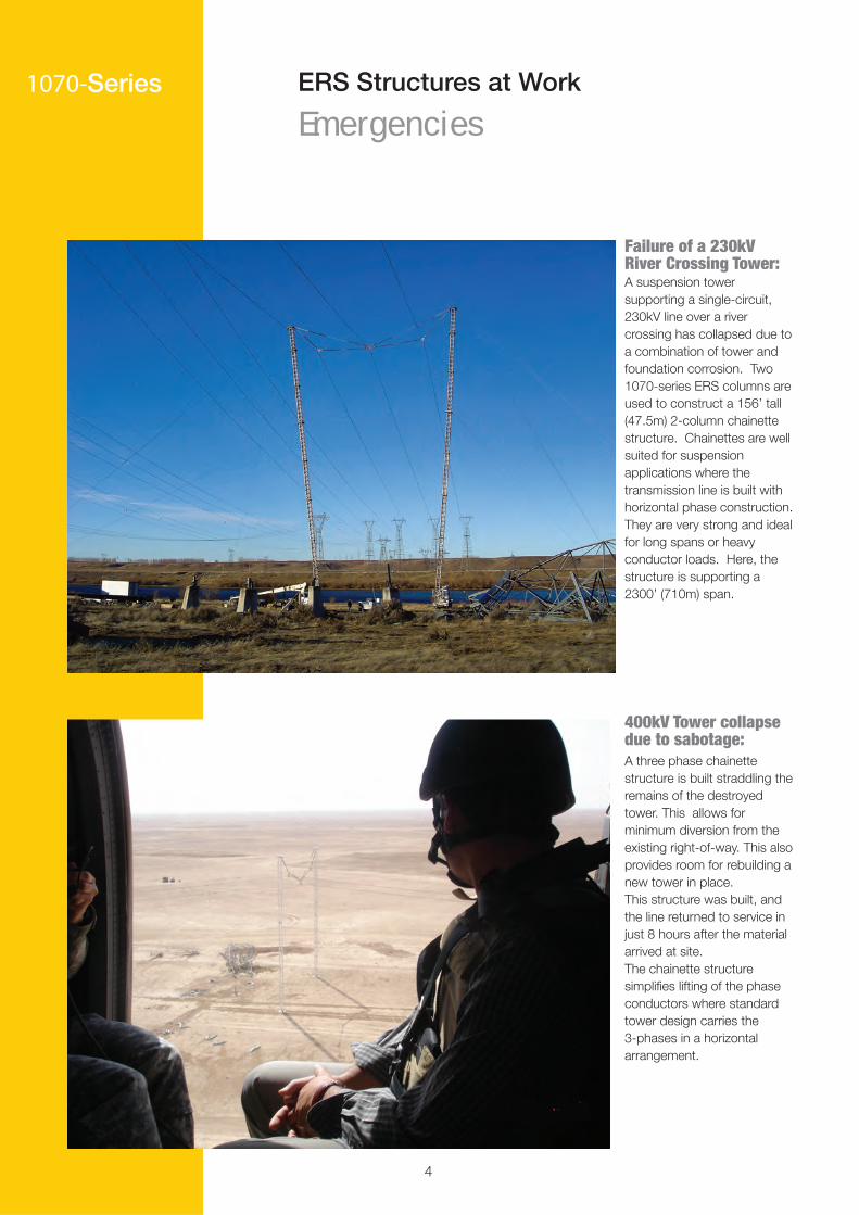
Failure of a 230kV River Crossing Tower:A suspension tower supporting a single-circuit, 230kV line over a river crossing has collapsed due to a combination of tower and foundation corrosion. Two 1070-series ERS columns are used to construct a 156’ tall (47.5m) 2-column chainette structure. Chainettes are well suited for suspension applications where the transmission line is built with horizontal phase construction. They are very strong and ideal for long spans or heavy conductor loads. Here, the structure is supporting a 2300’ (710m) span.
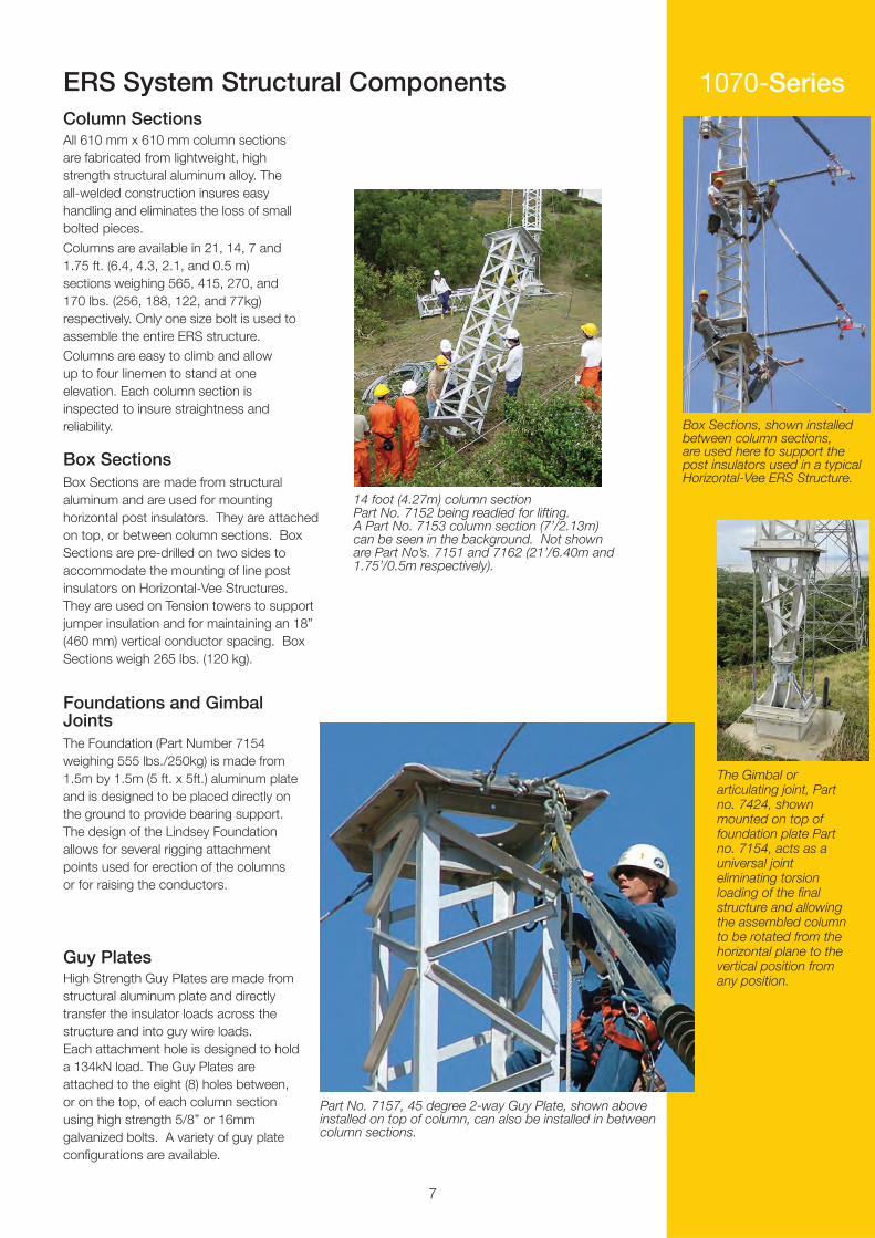
400kV Tower collapse due to sabotage:A three phase chainette structure is built straddling the remains of the destroyed tower. This allows for minimum diversion from the existing right‐of‐way. This also provides room for rebuilding a new tower in place.This structure was built, and the line returned to service in just 8 hours after the material arrived at site.The chainette structure simplifies lifting of the phase conductors where standard tower design carries the 3‐phases in a horizontal arrangement.
Emergencies
4

1070‐SeriesERS Structures at Work
Construction
Reconductoring: A string of ERS structures can be seen adjacent to the transmission line. The phase conductors of one circuit of the double circuit tower were moved to the ERS structures. The line was then re-energized allowing for new conductors to be strung on the permanent towers. Here, the reconductoring is completed and the ERS structures will be moved to the other side of the towers for reconductoring of the second circuit.
Tower Replacement:A series of Lindsey ERS structures have been used to offload the conductors from a 500kV transmission tower which needed replacement. In the center is the new tower, in the process of being strung. Two, single-phase herringbone structures support one phase (shown). Sturctures used to support the other two phases have already been dismantled.
Lindsey ERS structures are widely used during line and substation construction projects. The ability to quickly and temporarily relocate conductors and line segments provides great flexibility during project work. Lindsey ERS structures allow for adapting to almost any situation and are widely used by utilities and contractors alike.
5

Elements of an Effective Emergency Restoration SystemAn effective ERS system consists of three core elements:
Modular structuresAnalysis tools and advanced planningField training
Modular Structures
Field Training
1070‐Series
Two of the most difficult requirements for restoration of a damagedtransmission line are construction of a new foundation and replacementof damaged tower steel. Tower steel is often stocked; however,predicting the requirements for every possible failure and stocking allthe necessary material is difficult and uneconomical. Similarly, construction projects may require a wide range of tower configurationsthat are difficult to foresee.
Lindsey series-1070 structures are a more effective and economic solution. They provide a system of modular components that can be arrangedin virtually unlimited configurations to meet restoration and construction needs. Key features include:
Analysis Tools and Advanced Planning
Efficient use of ERS structures requires properly trained and experienced field personnel. Lindsey offers training services in the assembly and erection of the series-1070-series structures. Training covers various erection techniques using a variety of equipment.Lindsey works closely with the asset owner, drawing on over three decades of experience in emergency restoration, to develop techniques that are appropriate for each utility’s unique situation.
All Lindsey ERS systems includes ProSpot® software, an ERS design and analysis package that can be used to plan the design and placement ofthe Lindsey ERS structures. It is designed for ease of use, requires minimal input, and provides clear output for field personnel.
The asset owner’s engineering staff should pre-design those restoration structures most likely expected to be used, and be trained to quickly analyze any special emergency situation that occurs.
A pre-designated Basic Chainette for 400kV allows field crews to quickly build a structure without waiting for additional engineering.
6
Lightweight welded aluminum construction for ease of transport, rapid installation, long-term storage, and durability.
No special foundation requirements.
Usable at any voltage level, AC or DC.
Suitable for suspension, angle, or tension.
1070‐SeriesERS System Structural Components
All 610 mm x 610 mm column sections are fabricated from lightweight, high strength structural aluminum alloy. The all-welded construction insures easy handling and eliminates the loss of small bolted pieces.
Columns are available in 21, 14, 7 and 1.75 ft. (6.4, 4.3, 2.1, and 0.5 m) sections weighing 565, 415, 270, and 170 lbs. (256, 188, 122, and 77kg) respectively. Only one size bolt is used to assemble the entire ERS structure.Columns are easy to climb and allowup to four linemen to stand at oneelevation. Each column section isinspected to insure straightness andreliability.
Foundations and GimbalJoints
Box Sections are made from structural aluminum and are used for mounting horizontal post insulators. They are attached on top, or between column sections. Box Sections are pre-drilled on two sides to accommodate the mounting of line post insulators on Horizontal-Vee Structures. They are used on Tension towers to support jumper insulation and for maintaining an 18” (460 mm) vertical conductor spacing. Box Sections weigh 265 lbs. (120 kg).
Guy Plates
The Foundation (Part Number 7154 weighing 555 lbs./250kg) is made from 1.5m by 1.5m (5 ft. x 5ft.) aluminum plate and is designed to be placed directly on the ground to provide bearing support. The design of the Lindsey Foundation allows for several rigging attachment points used for erection of the columns or for raising the conductors.
High Strength Guy Plates are made fromstructural aluminum plate and directly transfer the insulator loads across the structure and into guy wire loads. Each attachment hole is designed to hold a 134kN load. The Guy Plates are attached to the eight (8) holes between, or on the top, of each column section using high strength 5/8” or 16mm galvanized bolts. A variety of guy plate configurations are available.
Box Sections
Part No. 7157, 45 degree 2-way Guy Plate, shown above installed on top of column, can also be installed in between column sections.
The Gimbal or articulating joint, Part no. 7424, shown mounted on top of foundation plate Part no. 7154, acts as a universal joint eliminating torsion loading of the final structure and allowing the assembled column to be rotated from the horizontal plane to the vertical position from any position.
7
Box Sections, shown installed between column sections, are used here to support the post insulators used in a typicalHorizontal-Vee ERS Structure.
14 foot (4.27m) column section Part No. 7152 being readied for lifting. A Part No. 7153 column section (7’/2.13m) can be seen in the background. Not shown are Part No’s. 7151 and 7162 (21’/6.40m and 1.75’/0.5m respectively).
Column Sections

Series 1070 ERS Accessories1070‐SeriesInsulators and Hardware
Anchors
Anchoring is a critical element of any guyed Lindsey Emergency Restoration System. Depending on the prevailing soil conditions, a number of different anchoring arrangements can be provided. In general, Lindsey does not recommend temporary anchors for construction, but only the use of the permanent anchors during construction of the structures.
For normal soil conditions, hydraulically installed self-locking type anchors can be installed in 15-20 minutes. The advantage of these type anchors, besides their speed of installation in normal soils, is that they are proof tested during installation. Anchor installation kits are supplied with these types of anchors.
Cross plate anchors are a very common and universal anchoring method, requiring minimal installation equipment. In normal soils, each cross plate anchor will require approximately 4 hours to install by hand.
Rock anchors and dead weight anchoring systems can also be supplied to meet specific requirments.
Installing and final locking of the normal soil density hydraulically installed self locking anchor. Anchor installation kit shown at right.
Lindsey guarantees the assembly and fit of all hardware assemblies.
8
Light weight, non-ceramic insulators are supplied with Lindsey ERS structures. These insulators conform to all applicable electrical and mechanical tests as required by both ANSI and IEC standards. Insulators meeting utility specific special requirements are also available.
A minimum number ofdifferent types ofhardware are to be provided in order to minimizeconfusion during emergencies. For example, onlyone size of anchorshackle is provided.All hardware will haveultimate load ratings towithstand the maximumstructure loading. All ferrous materials are galvanized. Routine mechanical pull tests are to be applied to all hardware items in accordance with IEEE Std 135.61-1997.
Manual helix anchor installation tool
For normal or low-density soil conditions, i.e. swamp or peat, high strength triple helix screw anchors can be provided.
Cross plate anchor

Series 1070 ERS Accessories
Figure Art of a Trifor grip hoist and three Ton Reversible Chain Hoist attached to an Anchor Construction Yoke, which is attached to a Pulling Eye and an Anchor.
1070‐SeriesConstruction ToolsAll necessary construction tools and hand tools can be provided for assembly, erection and lifting of the conductors of a complete emergency restoration structure.
The Lindsey R-16289 Gin Pole.
The Lindsey 7004 Capstan and Hydraulic Power Supply.
7060 Double Roller Clamps These clamps simplify stringing.
PERMANENT ANCHOR
CONSTRUCTION YOKEPLATE
3 TON CHAIN HOIST
TIRFUR CABLE TO COLUMN SECTION
TIRFUR CABLE TO COLUMN SECTION
PULLING EYE
AUTOMATIC GRIP ONPERMANENT GUY WIRE
7060 Double Roller Clamps (optional) combine the function of a double stringing roller and a conductor clamp, simplifying conductor installation.
7004 Hydraulic Capstan (optional) is a 1-ton hydraulic capstan winch with foot pedals. This capstan is capable of being powered by the same hydraulic power unit used to install anchors.
All necessary snatch blocks and rigging ropes are included. The gin pole davit arm keeps loads clear of the structure while being raised by manpower, or a capstan with hydraulic power unit.
R-16289 Gin Pole (optional) is designed to support manual installation of ERS. Made from aluminum alloy, the gin pole is supported on one corner of a column section and allows for the lifting of column sections, insulators, or other accessories to the top of the structure.
-
-
9
Worker Platforms (optional) attach to the column sections and provide a flat working surface for linemen as they work on insulator strings and conductor hardware. Work platforms (aka diving boards) of
various lenghts are available.

Storage and Transportation
Storage
1070‐Series
The lightweight modules that make up Lindsey ERS system structures provide great flexibility in moving the system to the job site. Containers can be transported near the job site and unloaded. From there, the ERS Structures can be taken to the construction site by hand, small truck or helicopter.
Field Transport
ERS system structural components can also be store outdoors as they are made from corrosion resistant, high-strength, 6061-T6 aluminum alloy. Unlike galvanized structures, these can be stored outside indefinitely, even in marine environments.
ERS systems are intended for rapid deployment in times of emergency. Lindsey 1070-Series column sections can be shipped in 40-foot ocean cargo storage containers or on standard flat bed trucks. Other components (tools, insulators, and accessories) are shipped in standard 20-foot ocean cargo storage containers, ensuring all ERS system components are kept together and readily transportable to site.
Standard containers contain ERS gimbals and foundations, associated insulators and hardware, anchors and guy wireSpecially fitted tool containers are provided when optional construction tools are orderedCustom container designs to meet special requirements are available
10

Construction Methods
Safety
Construction Methods and Safety1070‐Series
Lindsey ERS system structures are compatible with a wide variety of construction methods, including:
The enhanced safety features of the 1070‐series Lindsey ERS make all tower climbing activities secure, safe, and comfortable for field personnel.
Manpower only utiizing a Gin PoleWinch Line and Erection JibSmall or large cranesHelicopter
This flexibility allows for rapid structure erection in any terrain or environment.
Full compatibility with all commercially available fall arrest systemsensure personnel are using familiar equipment and methods.
Flat climbing surfaces on all sides provide for comfortable, fatiguefree, secure footing. This eliminates the need to carry detachablesteps.
Man‐width tower design provides for up to four workmen to standcomfortably at the same level. Unlike narrow tower designs where aworkman must straddle the tower corners, this allows multiple workmento assist each other.
Above, Winch Line and Erection Jib: ERS columns can be tited up with a winch line and the optional Erection Jib. Erection jibs can also be used to lift heavy loads to the top of an ERS column.
Cranes: Cranes allow for assembly onthe ground and rapid ERS installation.
Helicopter:Helicopters can either help to right columns built on the ground, or carry them to site.
Left, Manpower and Gin Pole: 230kV tension structure built only by manpower in the Himalayas. The ERS structure spanned 710m to the structure circled in red.
Photo taken during a training session, showing how four linemen can work at the same level of the Lindsey ERS structure.
11

Training and Technical SupportTrainingTraining sessions for personnel not failiar with an ERS system is crucial. Lindsey offersboth on-site and off-site training services for both comprehensive training and refreshercourses. All training is conducted by experience application engineers.
Classroom TrainingClassroom training can be on‐site or off‐site. It is customized to fit your organization’srequirements and can include:• Emergency Restoration System fundamentals.• Restoration scenario analysis.• ProSpot® ERS Design software training for engineering staff.
Field TrainingField training is usually conducted on the ERS owner’s site, though it may also be conducted at a third party location. Use of the asset owners equipment ensures linemen can focus on the ERS system, not newequipment. Field training may include:• Actual field construction of a variety of ERS structures.
• Training and practice using several construction techniques including crane and helicopter techniques if desired.
Technical Support ServicesBesides training, Lindsey offers a variety of technical support services, including:Order Support: Lindsey can assist your operations and engineering personnel to determine the most efficient and economic ERS system to meeting the unique needs of your system or applica-tion. A form detailing information needed to preparing a budgetary quotation is available at: www.lindsey‐usa.com/ers‐formInventory Review: Whether an ERS structure has been in storage for ten years, or was used last week, a periodic inventory review is a best practice. It may be necessary to replenish consum-ables like anchors, replace worn items such as guy grips, or replace any items that may have been unintentionally damaged or have gone missing. Lindsey can send an ERS engineer to help perform a proper inventory.Restoration Scenario Support: Lindsey engineers can assist in analyzing various transmission tower failure situations and developing appropriate restoration scenarios.
1070-Series
12
ProSpot Structural Analysis Software 1070‐Series
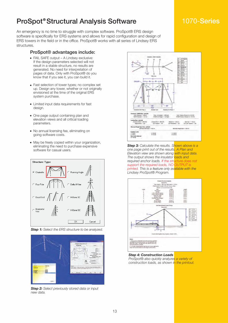
Step 3: Calculate the results. Shown above is a one page print out of the results. A Plan and Elevation view are shown along with input data. The output shows the insulator loads and required anchor loads. If the structure does not support the required loads, NO OUTPUT is printed. This is a feature only available with the Lindsey ProSpot® Program.
Step 4: Construction Loads ProSpot® also quickly analyzes a variety of construction loads, as shown in the printout.
Step 1: Select the ERS structure to be analyzed.
Step 2: Select previously stored data or input new data.
An emergency is no time to struggle with complex software. ProSpot® ERS design software is specifically for ERS systems and allows for rapid configuration and design of ERS towers in the field or in the office. ProSpot® works with all series of Lindsey ERS structures.
®
ProSpot® advantages include:FAIL SAFE output – A Lindsey exclusive: If the design parameters selected will not result in a stable structure, no results are generated. No need for interpretation of pages of data. Only with ProSpot® do you know that if you see it, you can build it.
Fast selection of tower types; no complex set up. Design any tower, whether or not originally envisioned at the time of the original ERS system purchase.
Limited input data requirements for fast design.
One page output containing plan and elevation views and all critical loading parameters.
No annual licensing fee, eliminating ongoing software costs.
May be freely copied within your organization, eliminating the need to purchase expensive software for casual users.
13

Examples of Structures1070‐Series
Running Angle:400kV single phase running angle towers.
Four Column: 500kV ERS built in oneday to support a line from a nuclear power plant.
Three‐phase single column: Horizontal Vee: Multiple 380kV ERS used to restore line where multiple structures were destroyed in a stright-line windstorm.
Delta: Part of bypass around 220kVcollapsed towers.
Full Tension: These full‐tension dead‐end structures were built to support the line while a permanent tower was being replaced.
14
Examples of Structures 1070‐Series
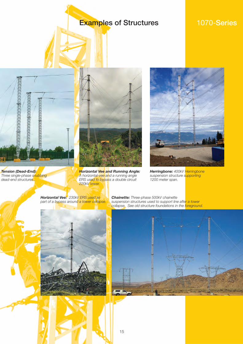
Horizontal Vee and Running Angle:A horizontal-vee and a running angle ERS used to bypass a double circuit 220kV tower.
Herringbone: 400kV Herringbone suspension structure supporting 1200 meter span.
Tension (Dead‐End): Three single-phase snubbing dead-end structures..
Horizontal Vee: 230kV ERS used as part of a bypass around a tower collapse.
Chainette: Three-phase 500kV chainettesuspension structures used to support line after a tower collapse. See old structure foundations in the foreground.
15
More Solutions to Enhance Transmission System Operations
Lindsey Manufacturing Co., dba Lindsey Systems760 N. Georgia Avenue | Azusa, CA 91702Tel. 1-626-969-3471 | www.lindsey-usa.com
©2020 Lindsey Systems, Lindsey, SMARTLINE, SMARTLINE-TCF, SMARTLINE-TAMPERand TLM are trademarks or registered trademarks of Lindsey Manufacturing Co.
Publication Number 07B-001 1070 ERS 10-2020
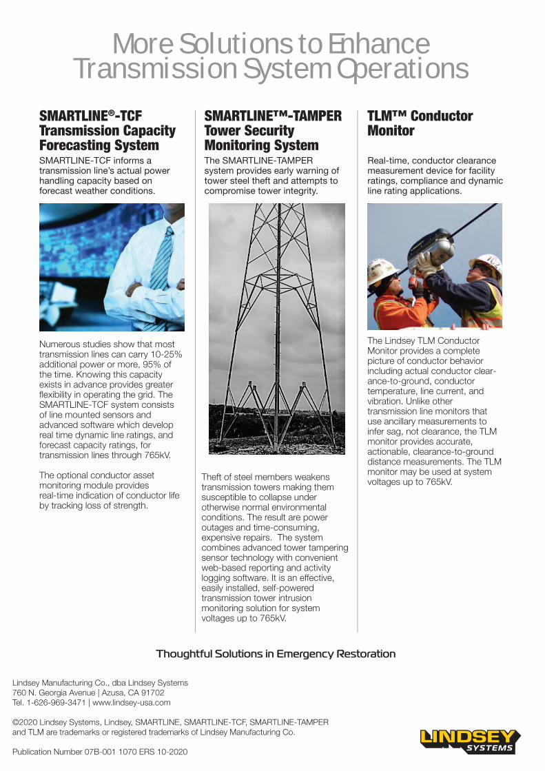
Theft of steel members weakens transmission towers making them susceptible to collapse under otherwise normal environmental conditions. The result are power outages and time-consuming, expensive repairs. The system combines advanced tower tampering sensor technology with convenient web-based reporting and activity logging software. It is an effective, easily installed, self-powered transmission tower intrusion monitoring solution for system voltages up to 765kV.
SMARTLINE™-TAMPERTower Security Monitoring SystemThe SMARTLINE-TAMPER system provides early warning of tower steel theft and attempts to compromise tower integrity.
Numerous studies show that most transmission lines can carry 10-25% additional power or more, 95% of the time. Knowing this capacity exists in advance provides greater flexibility in operating the grid. The SMARTLINE‐TCF system consists of line mounted sensors and advanced software which develop real time dynamic line ratings, and forecast capacity ratings, for transmission lines through 765kV.
The optional conductor asset monitoring module provides real-time indication of conductor life by tracking loss of strength.
SMARTLINE®-TCF Transmission Capacity Forecasting SystemSMARTLINE-TCF informs a transmission line’s actual power handling capacity based on forecast weather conditions.
The Lindsey TLM Conductor Monitor provides a complete picture of conductor behavior including actual conductor clear-ance‐to‐ground, conductor temperature, line current, and vibration. Unlike other transmission line monitors that use ancillary measurements to infer sag, not clearance, the TLM monitor provides accurate, actionable, clearance‐to-ground distance measurements. The TLM monitor may be used at system voltages up to 765kV.
TLM™ Conductor Monitor
Real‐time, conductor clearance measurement device for facility ratings, compliance and dynamic line rating applications.
Thoughtful Solutions in Emergency Restoration