Embed Size (px)
Citation preview

BGE, NHE Emerald Plus Series

Safety Precautions Before operating the generator set, read the Operator's Manual and become familiar with it and the ui ment. Safe and efficient operation can be achieved on T i y the unit is proper1 operated and maintained. Many accidents are
The following symbols, found throughout this manual, alert you to potentiall dangerousconditionsto the operator, service per-
This symbol warns of immediate haz- ards which will result in severe personal injuw or death. -1 Thissymbol refers to a hazard or unsafe practice which can result in severe personal iniury or death. -1 This symbol refers to a hazard or unsafe practlce which can result in personal lnjuw orprod- uct or propew damage. FUEL AND FUMES ARE FLAMMABLE. Fire, explosion, and personal injury can resutt from improper practices.
caused b y failure to follow fundamental rules and precautions.
sonnel, or b: e equipment;
DO NOT fill fuel tanks while engine is running. Fuel contact with hot engine or exhaust is a potential fire hazard. DO NOT SMOKE OR USE AN OPEN FLAME near the gen- erator set or fuel tank. Fuel lines must be adequately secured and free of leaks. Fuel connection at the engine should be made with an a p proved flexible, non-conductive line. Do not use copper pip- ing on flexible lines as copper will work harden and become bnttle. Be sure all fuel supplies have a positive shutoff valve.
GASOLINE AND LPG FUEL MAY BE ACCIDENTALLY IG- N E D BY ELECTRICALSPARKS, resentlng the hazard of
jury or death. When Installing the generator set: fire or exploslon, which can resu P t in severe personal ln-
Do not tie electrical wiring to fuel lines. Do not run electrical lines and fuel lines through the same compartment openings. Keep electrical and fuel lines as far apart as possible. Place a physical barrier between fuel lines and electrical lines wherever possible. If electrical and fuel lines must pass through the same com- partment opening, make certain that they are physically separated by running them through individual channels, or by passing each line through a separate piece of tubing. DO NOT SMOKE while servicing batteries. Lead acid bat- teries emit a highly explosive hydrogen gas that can be ig- nited by electrical arcing or by smoking.
EXHAUST GASES ARE DEADLY Neversleep inthe vehicle with thegenerator set running un- less vehicle is equipped with an operating carbon monoxide detector.
0 Provide an adequate exhaust system to properly expel dis- charged gases. Inspect exhaust system daily for leaks per the maintenance schedule. Be sure that exhaust manifolds are secure and not warped. Do not use exhaust gases to heat a compartment.
0 Be sure the unit is well vintilated.
JURY OR DEATH 0 Before starling work on the generator set, disconnect batter-
MOVING PARTS CAN CAUSE SEVERE PERSONAL IN-
ies. This will prevent accidental arcing.
Keep your hands away from moving parts.
Make sure that fasteners on the generator set are secure. lighten supports and clamps, keep guards in position over fans, drive belts, etc. r
Do not wear loose clothing or jewelry while working on gen- erator sets. Loose clothing and jewelry can become caught in moving parts. Jewelry can short out electrical contacts and cause shock or burning. If adjustment must be made whilethe unit is running, use ex- treme caution around hot manifolds, moving parts, etc.
ELECTRICAL SHOCK CAN CAUSE SEVERE PERSONAL INJURY OR DEATH
Disconnect starting battery before removing protective shields or touching electrical equipment. Use rubber insula- tive mats placed on dry wood platforms over floors that are metal or concrete when around electrical equipment. Do not weardampclothing (particularlywetshoes) orallow skin sur- faces to be damp when handling electrical equipment.
Use extreme caution when working on electrical compo- nents. High vottages can cause injury or death. Follow all state and local electrical codes. Have all electrical installations performed by a qualified licensed electrician. Tag open switches to avoid accidental closure. DO NOT CONNECT GENERATOR SET DIRECTLY TO ANY BUILDING ELECTRICAL SYSTEM. Hazardous volt- ages can flow from the generator set into the utility line. This creates a potential for electrocution or property damagi Connect only through an approved device and after buildir main switch is open. Consult an electrician in regard 1 emergency power use.
GENERAL SAFETY PRECAUTION$
Have afire extinguisher nearby. Maintain extinguisher prop- erly and become familiar with its use. Extinguishers rated ABC by the NFPA are appropriate for all applications. Con- sult the local fire department for the correct type of extin- guisher for various applications.
Hot coolants under pressure can cause severe personal in- jury. DO NOT open a radiator pressure cap while the engine is running. Stop the engine and carefully bleed the system pressure. Benzene and lead, found in some gasoline, have been iden- tified by some state and federal agencies as causing cancer or reproductive toxicity. When checking, draining or adding gasoline, take care not to ingest, breathe the fumes, or con- tact gasoline. Used engine oils have been identified by some state or fed- eral agencies as causing cancer or reproductive toxicaw. When checking or changing engine oil, take care not to in- gest, breathe the fumes, or contact used oil. Remove all unnecessary grease and oil from the unit. Accu- mulated grease and oil can cause overheating and engine damage, which presents a potential fire hazard.
DO NOTstore anything in the generator compartment such as oil or gas cans, oily rags, chains, wooden blocks, portablr propane cylinders, etc. A fire could result or the generatc set operation (cooling, noise and vibration) may be ac versely affected. Keep the compartment floor clean and dry.
Do not work on this equipment when mentally or physically fatigued, or after consuming any alcohol or drug that makes the operation of equipment unsafe.
#
Q
RV-9

Table of Contents \ SECTION TITLE PAGE
SAFETY PRECAUTIONS ................................ Inside Front Cover INTRODUCTION ..................................................... 1-1
”) About this Manual 1-1 1 .
How to Obtain Service .............................................. 1-1 2 SPECIFICATIONS ................................................... 2-1 3 OPERATION ........................................................ 3-1
Before Starting .................................................... 3-1 Recommended Fuels ............................................... 3-1 Starting and Stopping .............................................. 3-2 Break-in Procedure ................................................ 3-2 Operating Conditions ............................................... 3-2 Generator Set Exercise ............................................. 3-3 Remote Control (Option) ................. .......................... 3-3 Troubleshooting Guide ............................................. 3-4
4 MAINTENANCE ..................................................... 4-1
Periodic Maintenance Schedule ..................................... 4-1 General Inspection ................................................. 4-2 Lubrication System ................................................. 4-2 Battery Care ....................................................... 4-3 Spark Arrester ..................................................... 4-4 Governor Linkage .................................................. 4-4 Air Filter .......................................................... 4-4 Fuel Filter (Gasoline) ............................................... 4-4 Fuel Filter (LPG Fuel) ............................................... 4-5 Spark Plugs ....................................................... 4-6 Lowering and Raising the Under-Floor Mount Set ..................... 4-6 Cleaning the Generator Set ......................................... 4-8 Cleaning Carburetor and Combustion Chamber ....................... 4-8 Inspect and Clean Engine (Internal) .................................. 4-9 Out-of-Service Protection .......................................... 4-9
.................................................
General ........................................................... 4-1
I


Section 1 a Introduction
ABOUT THIS MANUAL This manual provides information for operating and maintaining the Onan BGE/NHE gasoline and liquid withdrawal/LPG models of recreational vehicle genera- . tor sets. This manual covers both conventional com- partment mount and underfloor mount installations.
Study this manual carefully and observe all warnings and cautions. Using the generator set properly and fol- lowina a reaular maintenance schedule can result in
When the generator set requires servicing, contact an Onan authorized service center for assistance. Onan factory trained parts and service representatives are ready to handle all service needs.The Parts and Service Center Directory F-118, included with your generator set, lists the Onan representative nearestyou. Copies of the warranty (AB-355) and parts catalog are also included in the literature package with your generator set.
When contacting an Onan authorized service center for parts or service, always supply the complete model number and serial number as shown on the Onan nameplate (Figure 1-1).
~
FIGURE 1-1. ONAN NAMEPLATE
I
1-1 . .


Section 2. Specifications
50 Hz
I
60 Hz
BGE
50 Hz I 60 Hz GENERAL Weight Control Fuse Fuel Pump/Autochoke Fuse F2
ENGINE Oil Capacity (includes filter) Tune-up Specifications
Spark Plug Gap Fuel Consumption - Gasoline
No-load Half-load Full-load
Fuel Consumption - Gasoline No-load Half-load Full-load
Fuel Consumption - LPG No-load Half-load Full-load
Speed (r/min)
GENERATOR Power (Watts) Voltage Current (Amperes)
BAllERY RECOMMENDATIONS
Size Capacity Cranking Current
204 Ib (92.5 kg) 5 Ampere
10 Ampere (gasoline sets only) ,
3.5 US. quarts (3.3 L)
0.025 in. (0.64 mm)
0.4 gal/hr (1.5 Uhr) 0.6 gal/hr (2.3 uhr) 0.8 galhr (3.0 uhr)
0.5 gal/hr (1.9 Uhr) 0.8 gaVhr (3.0 Uhr) 1.3 gaVhr (4.9 Uhr)
1500
4000 1 1 01220 or 120/240
36.4/18.2 or 33.3116.7
4000 BGE 0.4 galhr (1.5 Uhr) 0.6 galhr (2.3 Uhr) 0.8 gaVhr (3.0 Uhr)
5000 BGE: 0.4 galhr (I .5 Uhr) 0.7 gaVhr (2.6 Uhr) 1 .O gal/hr (3.8 Uhr)
0.5 gal/hr (1.9 Uhr) 0.8 gaVhr (3.0 Llhr) 1.3 gaVhr (4.9 Llhr)
1800
33.3 41.7
230 Ib (1 04 kg) 5 Ampere
10 Ampere (gasoline sets only)
3.5 U.S. quarts (3.3 L)
0.025 in. (0.64 mm)
0.4 gal/hr (1.5 uhr) 0.65 galhr (2.5 Uhr) 1 .O gal/hr (3.8 Uhr)
0.5 gal/hr (1.9 Uhr) 0.78 gal/hr (3.0 Uhr) 1.18 gal/hr (4.5 Uhr)
1500
5000 1 10/220 or 120/240
45.5122.7 or 41.7120.8
12 Volts
60 Amperes 360 Cold Cranking Amperes
0.4 galhr (1.5 Vhr) 0.7 galhr (2.5 Uhr) 1.3 gal/hr (4.9 Uhr)
0.65 gal/hr (2.5 Uhr) 1.05 gaVhr (4.0 Uhr) 1.70 gaVhr (6.4 Uhr)
1800
jaoline-6500, LPG-6300 120,
Sasoline-54.2, LPG-52.5
2-1
GOVERNOR ADJUSTMENTS
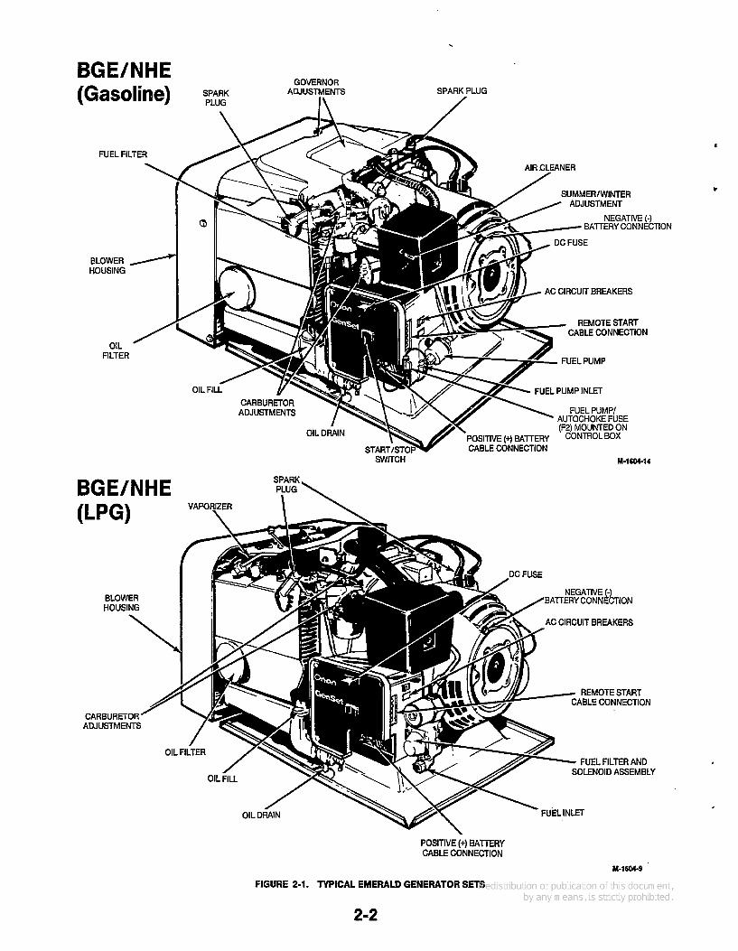
BGE/NHE SPARK PLUG
(Gasoline) I \ /
FUEL FILTER
SUMMER/ WINTER ADJUSTMENT
NEGATIVE (-) EATERY CONNEC
BLOWER HOUSING
AC CIRCUIT BREAKERS
REMOTE START CABLE CONNECTION
OIL FILTER
FUEL PUMP INLET
AUTOCHOKE FUSE (F2) MOUNTED ON
POSITIVE (+) BATTERY CABLE CONNECTION
SWITCH M-1604-14
SPARK BGE/NHE PLUG \
:TION
AC CIRCUIT BREAKERS
REMOTE START ABLE CONNECTION
CARBURETOR ADJUSTMENTS
FUEL FILTER AND SOLENOID ASSEMBLY
POSITIVE (+) BAlTERY CABLE CONNECTION
FIGURE 2-1. TYPICAL EMERALD GENERATOR SETS
2-2
M-1604-9

Section 3. Operation l AWARNING I
EXHAUST GAS IS DEADLY! Exhaust gases contain carbon monoxide, an odorless and colorless gas. Carbon monoxide is poisonous and can cause unconsciousness and death. Symptoms ot carbon monoxide poisoning can include:
0 Dizziness Nausea Muscular Twitching
0 Headache Vomiting Weakness and Sleepiness
Throbbing in Temples
Inability to Think Coherently
IF YOU OR ANYONE ELSE EXPERIENCE ANY OF THESE SYMPTQMS, GET OUT INTO THE FRESH AIR IMMEDIATELY. If symptoms persist, seek medical atten- tion. Shut down the unit and do not operate until it has been inspected and repaired.
Never sleep in vehicle with the generator set running unless the vehicle interior is equipped with an operating carbon monoxide detector. Protection against carbon monoxide inhalation also includes proper exhaust system installation and visual and audible inspection of the complete exhaust system at the start of each generator set operation.
BEFORE STARTING General Inspection Before starting, open generator set access panel/door and perform visual inspection of unit and exhaust sys- tem. Look for loose or damaged components and fas- teners. Correct as necessary.
Exhaust gas presents the hazard of lAWAR"Gl severe personal injury or death. Make sure all the exhaust components am operation- worthy and secure.
Do not start generator set undera load condition. Check that vehicle switching device (if equipped) is at utility position, or vehicle AC distribution panel breakers are off. See Starting and Stopping, this section.
Confirm that vehicle is not parked in high grass or brush.
Fire can cause severe personal 1AWAR"GI injwy or death. Do not operate the generator set when the vehicle is parkedin high grass or brush.
Do not operate the generator set if exhaust gases will not effectively expel away from vehicle.
Exhaust gases can cause severe personalinjury or death. Never oper-
ate the generator set unless the exhaust system is clear ot walls, snow banks, or any obstruction that can prevent exhaust gases from dissipating. Never operate any exhaust fan in the recreational vehicle when the generator set is running. Et can draw exhaust gas into the vehicle interior.
Lubrication Check the engine oil level. Keep the oil level as near as possible to the oil fill level indicator FULL mark. Do not overfill. See the Maintenance section for procedures.
Hot oil can cause severe burns if spilled or splashed on skin. Keep fin-
gers and hands clear when removing oil drain plug, and wear protective clothing.
Fuel Make sure the fuel tanks are full. See "Recommended Fuels" following.
Fuel presents the hazard of fire or explosion which can result in severe
personalinjury or death. Do not allow any spark, flame, pilot light, lit cigarette, or any other ignMon sources around fuel or fuel system components. Keep a type ABC fire extinguisher nearby.
RECOMMENDED FUELS Gasoline Models Use clean, fresh, unleaded or regular grade gasoline. Using unleaded gasoline results in extended periods between service, longer spark plug life, and reduced carbon clean-out maintenance. If regular gasoline is used, lead deposits must be removed from the cylinder heads as required to reduce engine power loss. Unleaded gasoline can be used safely after regular gasoline usage if lead deposits have been removed from the cylinder head areas.
3-1
Alternating between unleaded and liiZESl lead& (regular) gasoline can result in engine damage unless lead deposifs are removed trom the cylinder head areas before using unleaded gasoline again.
LPG Models Use clean, fresh commercial propane or HD-5 grade liquid propane gas in a mixture of at least 90 percent propane. Propane fuels other than HD-5 can contain more than 2.5 percent butane which can result in poor fuel vaporization and poor engine starting in low ambient temperatures (below 32°F or 0°C).
A manual shutoff valve must be mounted on the propane fuel supply tank.Thissupplytankvalvemwt beopenedfully whenoperating the generator settoensuretheexcess flow valvewillclosewitha broken propane fuel line.
STARTING AND STOPPING The following are general starting and stopping proce- dures. For initial start-up of unit, refer to Break-in Procedure.
At temperaturesof 4OoF (4OC)and below, disconnect all loads before attempting to start generator set.
1. Push the start-stop switch to the START position at the generator set control or at remote control (if equipped). Release the switch when the generator set starts.
2. Allow unit to warm up before connecting a load. During warm-up, observe unit operation. Confirm that unit performance is satisfactory.
3. Apply loads. Refer to Specifications section for generator set output and performance ratings. Refer to Table 3-1 for the approximate wattage usage of common appliances.
Continuous generator set overload- (BCAUTIONI ing can cause high operating temperatures that can damage the generator windings. Keep the load wifhin the nameplate rating.
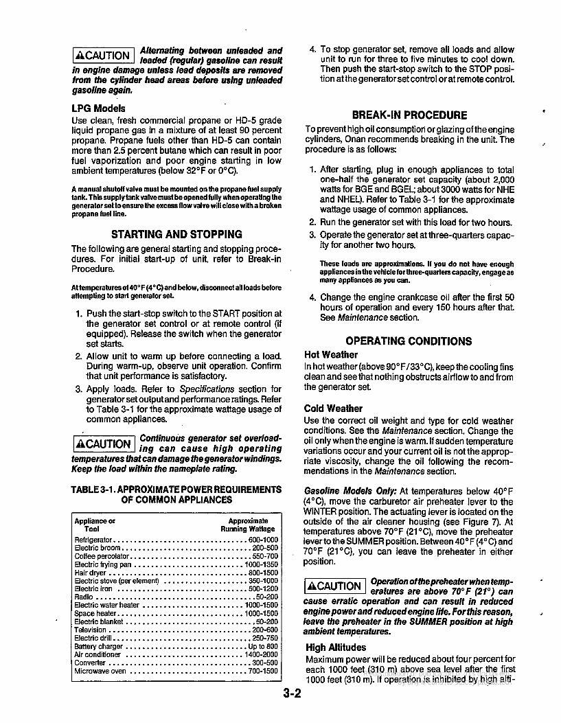
TABLE 3-1. APPROXIMATE POWER REQUIREMENTS OF COMMON APPLIANCES
Appliance or Approximate
Refrigerator. .............................. .600-1000 Electric broom.. ............................ .200-500 Coffee percolator. ........................... .SO-700 Electric frying pan ......................... . lOOO-1350 Hair dryer ................................ .800-1500 Electric stove (per element) ................... .350-1000 Electric iron .............................. .500-1200 Radio ...................................... 50-200 Electric water heater ........................ 1000-1500 Space heater. ............................ .1000-1500 Electric blanket .............................. .50-200 Television ................................. .200-600 Electric drill. ............................... .250-750 Battery charger ............................. Up to 800 Air conditioner ........................... .1400-2000 Converter .................................. 300-500 Microwave oven ........................... .700-1500
Tool Running Wattage
4. To stop generator set, remove all loads and allow unit to run for three to five minutes to cool down. Then push the start-stop switch to the STOP posi- tion at the generator set control or at remote control.
BREAK-IN PROCEDURE To prevent high oil consumption or glazing of the engine cylinders, Onan recommends breaking in the unit The procedure is as follows:
J
1. After starting, plug in enough appliances to total one-half the generator set capacity (about 2,000 watts for BGE and BGEL; about 3000 watts for NHE and NHEL). Refer to Table 3-1 for the approximate wattage usage of common appliances.
2. Run the generator set with this load for two hours. 3. Operate the generator set at three-quarters capac-
ity for another two hours.
These loads are approximations. If you do not have enough appliancesin the vehicle forthree-quarterseapacity, engage as many appliances as you can.
4. Change the engine crankcase oil after the first 50 hours of operation and every 150 hours after that. See Maintenance section.
OPERATING CONDITIONS Hot Weather In hot weather (above 90°F/33"C), keep the cooling fins clean and see that nothing obstructs airflow to and from the generator set
Cold Weather Use the correct oil weight and type for cold weather conditions. See the Maintenance section. Change the oil only when the engine is warm. If sudden temperature variations occur and your current oil is not the approp- riate viscosity, change the oil following the recom- mendations in the Maintenance section.
Gasoline Models Only: At temperatures below 40" F (4"C), move the carburetor air preheater lever to the WINTER position. The actuating lever is located on the outside of the air cleaner housing (see Figure 7). At temperatures above 70°F (21 "C), move the preheater lever to the SUMMER position. Between 40°F (4°C) and 70°F (21"C), you can leave the preheater in either position.
-1 Operation of fhepreheater when temp- eratures are above 70°F (21") can
cause erratic operation and can result in reduced engine power and reduced engine lite. For this reason, leave the preheater in the SUMMER position at high ambient temperatures.
High Altitudes Maximum power will be reduced about four percent for each 1000 feet (310 m) above sea level after the first 1000 feet (310 m). If operation is inhibited by high alti-
.1
3-2
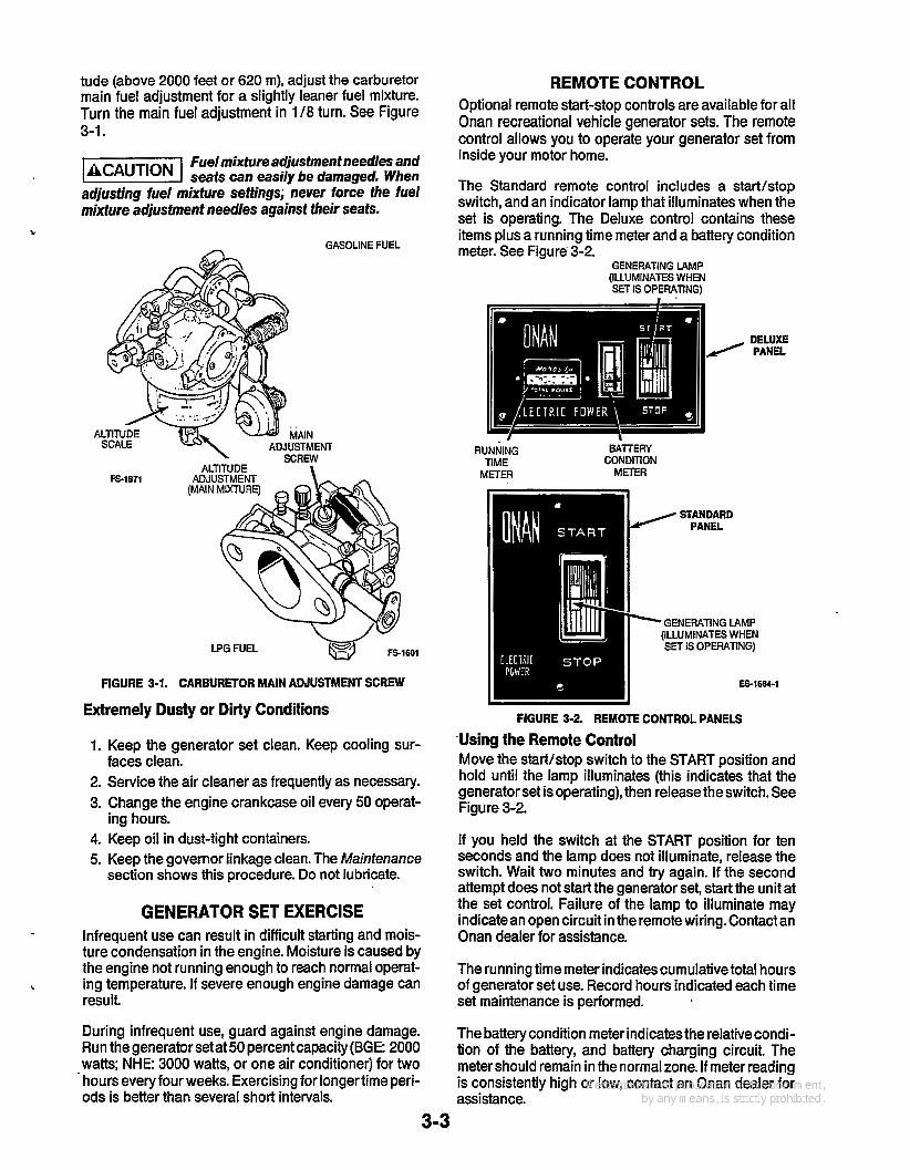
tude (above 2000 feet or 620 m), adjust the carburetor main fuel adjustment for a slightly leaner fuel mixture. Turn the main fuel adjustment in 1 /8 turn. See Figure
Fue/mixfureadjustment needles and seats can easily be damaged. Wben
adjusting fuel mixture settings; never iorce the fuel mixture adjustment needles against their seats.
3-1.
GASOLINE FUEL A
A
LPG FUEL w - @ FS-1601
FIGURE 3-1. CARBURETOR MAIN ADJUSTMENT SCREW
Extremely Dusty or Dirty Conditions
1. Keep the generator set clean. Keep cooling sur-
2. Service the air cleaner as frequently as necessary. 3. Change the engine crankcase oil every 50 operat-
4. Keep oil in dust-tight containers. 5. Keep the governor linkage clean. The Maintenance
section shows this procedure. Do not lubricate.
faces clean.
ing hours.
GENERATOR SET EXERCISE Infrequent use can result in difficult starting and mois- ture condensation in the engine. Moisture is caused by the engine not running enough to reach normal operat-
result. b ing temperature. If severe enough engine damage can
REMOTE CONTROL Optional remote start-stop controls are available for all Onan recreational vehicle generator sets. The remote control allows you to operate your generator set from inside your motor home.
The Standard remote control includes a startlstop switch, and an indicator lamp that illuminates when the set is operating. The Deluxe control contains these items plus a running time meter and a battery condition meter. See Figure 3-2.
GENERATING LAMP (ILLUMINATES WHEN SET IS OPERATING)
DELUXE / PANEL
RUNNING TIME
METER
BATERY CONDITION
METER
STANDARD PANEL
'GENERATING LAMP (ILLUMINATES WHEN SET IS OPERATING)
i84-1
FIGURE 3-2. REMOTE CONTROL PANELS
'Using the Remote Control Move the startistop switch to the START position and hold until the lamp illuminates (this indicates that the generator set is operating), then release the switch. See Figure 3-2.
If you held the switch at the START position for ten seconds and the lamp does not illuminate, release the switch. Wait two minutes and try again. If the second attempt does not start the generator set, start the unit at the set control. Failure of the lamp to illuminate may indicatean open circuit in theremote wiring. Contact an Onan dealer for assistance.
The running time meter indicates cumulative total hours of generator set use. Record hours indicated each time set maintenance is performed.
During infrequent use, guard against engine damage. Run the generator setat50 percentcapacity(BGE: 2000
-watts; NHE: 3000 watts, or one air conditioner) for two hours every four weeks. Exercising for longertime perk ods is better than several short intervals.
The battery condition meter indicates the relative condi- tion of the battery, and battery charging circuit. The meter should remain in the normal zone. If meter reading is consistently high or low, contact an Onan dealer for assistance.
3-3

TABLE 3-2. TROUBLESHOOTING GUIDE
Table 3-2 is a simplified troubleshooting guide. If these recommendations fail to resolve the problem, contact an Onan service center.
Problem Probable Cause Solution FAILS TO CRANK 1. Low battery.
2. Bad battery connection.
3. Blown fuse.
1. Check battery electrolyte level. 2. Clean and tighten all battery and
cable connections. 3. Replace fuse on control box. See
specifications for proper fuse rating.
CRANKS SLOWLY 1. Low battery. 1. Check battery electrolyte level. 2. Bad battery connection.
3. Oil is too heavy. 4. Load connected.
2. Clean and tighten all battery and
3. Replace with lighter oil. 4. Remove load.
cable connections.
CRANKS BUT WON’T START 1. Fuel below genset pick-up level 1. Add fuel.
2. Fuel supply shutoff valve closed. 2. Fully open fuel supply valve. 3. Carbon deposits on spark plugs. 3. Remove spark plugs and clean. 4. Blown fuel pump/ 4. Replace fuse with same type and
rating. If problem persists, see Onan service center.
in tank.
autochoke fuse F2.
EXHAUSTING BLACK SMOKE 1. Rich fuel mixture.
2. Dirty air filter. 3. Choke stuck.
1. Turn main fuel adjustment in 1/8 turn (location of adjustment is shown in Figure 3-1).
2. Replace air filter. 3. Contact an Onan service center.
UNIT RUNS THEN STOPS 1. Out of fuel. 2. Low oil level. 3. Excess oil.
1. Refill fuel tank. 2. Add oil if necessary. 3. Reduce engine oil level.
UNIT RUNS BUT SURGES 1. Loose or worn spark. 1. Check security of spark plug leads at spark plugs and ignition coil. Replace leads if worn.
2. Contact an Onan representative.
3. Remove and clean or replace
4. Contact an Onan service center.
plug leads.
components defective. 2. Ignition coil, wiring, or control
3. Faulty spark plugs.
4. Governor out of adjustment. spark plugs.
CIRCUIT BREAKER(s) TRIP 1. Too much load. 1. Reduce other AC loads (microwave, curling iron, etc.) when operating air conditioner(s).
A hot generator sef can cause severe @@%!%I burns. Always allow the generator set to cool before performing any maintenance or service.
3-4

Section 4. Maintenance
GENERAL If you have the under-floor mount generator set and it Establish and adhere to a definite schedule for mainte-
extreme operating conditions, you should reduce the intervals accordingly.
must be lowered for any maintenance procedure (that is,
procedure "Lowering the Under-Floor mount Genew- tor Set'' in this section before beginning the mainte- nance procedure.
nance and service. If the generator set is subjected to You cannot service it in its M"IIal position), see the
Consult your Onan dealer if the generator set will be subjected to any extreme operating conditions and determine a suitable maintenance schedule. Keep an accurate log of all service and maintenance performed for warranty support.
Accidental staffing of the generafor FiEEEl set during maintenance procedures can cause severe personalinjury or death. Disconnect both generator set sfaffing baftery cables before per- forming mainfenance; disconnect negative (-) cable -
Perform all the maintenanceat the time period indicated or after the number of operating hours indicated. Use the schedule to determine the maintenance required, and then refer to the sections that follow for the correct
first.
procedures. TABLE 4-1. PERIODIC MAINTENANCE SCHEDULE
1 - Before operating the set each day, or at least every 8 hours, check for oil and fuel leaks. Check exhaust system audibly and visually with generatorsetrunning.Shutdown thesetand repair any leaks immediately.Replacecorrodedexhaustandfuel linecomponents before leaks occur. Make sure exhaust pipe extends beyond the perimeter of the RV.
2 - Or once a year, whichever is first. Perform more often in extremely dusty conditions (Le., check monthly, and change if dirty). 3 - Replace fuel filter at carburetor, clean screen at fuel pump5. 4 - Refer to Out-of-Service Protection if unit is to be stored. 5 - Have your Onan service center perform. 8 - First oil change during first year or 50 hours of operation, whichever is first 7 - During periods of nonuse, exercise for 2 hours every 4 weeks. * - Replace if necessary. 9 - Perform more frequently if there are extended periods of nonuse.
4-1
GENERAL INSPECTION Perform a general inspection of the generator set before operation each day or at least every eight operating hours. Start the generator set, and check for visible and audible irregularities. Make sure the exhaust pipe extends beyond the perimeter of the RV.
LUBRICATION SYSTEM The engine oil was drained from the crankcase prior to shipment. Before the initial start, the engine must be filled with oil of the recommended classification and viscosity. Refer to the Specificationssection for the lub- ricating oil capacity. 4
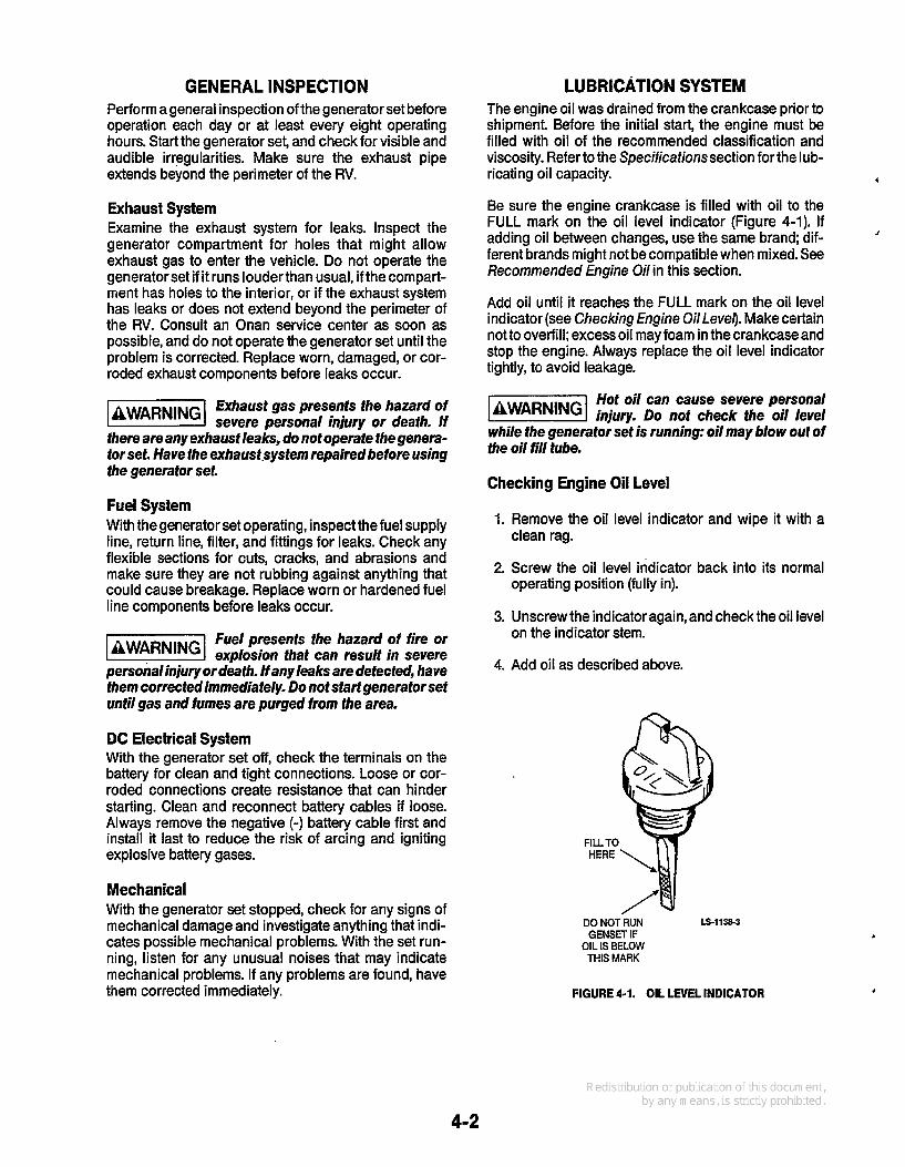
Be sure the engine crankcase is filled with oil to the FULL mark on the oil level indicator (Figure 4-1). If adding oil between changes, use the same brand; dif- ferent brands might not becompatible when mixed. See Recommended Engine Oil in this section.
Add oil until it reaches the FULL mark on the oil level indicator (see Checking Engine OilLevel). Make certain not to overfill; excess oil may foam in thecrankcaseand stop the engine. Always replace the oil level indicator tightly, to avoid leakage.
J
Exhaust System Examine the exhaust system for leaks. Inspect the generator compartment for holes that might allow exhaust gas to enter the vehicle. Do not operate the generator set if it runs louder than usual, if the compart- ment has holes to the interior, or if the exhaust system has leaks or does not extend beyond the perimeter of the RV. Consult an Onan service center as soon as possible, and do not operate the generator set until the problem is corrected. Replace worn, damaged, or cor- roded exhaust components before leaks occur.
Exhausf gas presenfs fhe hazard of severe personal iniury or deafh. If
there are any exhaust leaks, do not operate the genera- for set. Have fhe exhausf.sysfem repairedbefore using the generafor set.
Fuel System With the generator set operating, inspect the fuel supply line, return line, filter, and fittings for leaks. Check any flexible sections for cuts, cracks, and abrasions and make sure they are not rubbing against anything that could cause breakage. Replace worn or hardened fuel line components before leaks occur.
Fuel presents the hazard of fire or explosion fhaf can result in severe
personalinjury ordeafh. If any leaks are detected, have fhem correctedimmediafely. Do not sfart generafor sef until gas and fumes are purged from fhe area.
DC Electrical System With the generator set off, check the terminals on the battery for clean and tight connections. Loose or cor- roded connections create resistance that can hinder starting. Clean and reconnect battery cables if loose. Always remove the negative (-) battery cable first and install it last to reduce the risk of arcing and igniting explosive battery gases.
Mechanical With the generator set stopped, check for any signs of mechanical damage and investigate anything that indi- cates possible mechanical problems. With the set run- ning, listen for any unusual noises that may indicate mechanical problems. If any problems are found, have them corrected immediately.
Hot oil can cause severe personal lawnR"G1 injury. Do nof check the oil level while the generafor set is running: oil may blow out of the oil fill tube.
Checking Engine Oil Level
1. Remove the oil level indicator and wipe it with a
2. Screw the oil level indicator back into its normal
3. Unscrew the indicator again, and check the oil level
clean rag.
operating position (fully in).
on the indicator stem.
4. Add oil as described above.
FILL TO HERE
DO NOTRUN IS-1138-3 GENSt3 IF
OIL IS BELOW M I S MARK
FIGURE 4-1. OIL LEVEL INDICATOR
4-2

Oil Changing Procedures: Figure 1-2 shows the location of the oil drain, oil filter and oil level indicator. In dusty or dirty conditions, change the oil more frequently than specified in the Maintenance Schedule.
J Run the engine until warm before draining the oil.
Hot oil can cause severe burns if b @%@&I spilledorsplashedonskin. Keepfin-
gers and hands clear when removing oil drain plug, and wear protective clothing.
Oil Draining Procedure 1. Place a pan under the oil drain valve.
2. Open the valve and allow oil to drain from the
3. Close the valve. Dispose of the old oil properly.
engine.
Contact wifh used oil can cause k?@%@ cancer or reproductive toxicity. When checking or changing engine oil take care not to ingest, breath the fumes, or contact used oil.
Oil Fi/fer Changing Procedure: 1. Place an oil pan under the oil filter location on the
engine.
2. Turn the old filter slowly in a counterclockwise direction, wait for oil to stop draining, then remove filter.
3. Replace the oil filter only with a new Onan- approved oil filter. Coat the new filter gasket lightly with clean engine oil.
Incorrect replacement of ser- k%%!%l vice parts can result in damage to equipment. Use genuine Onan replacement fil- ters only.
4. Turn the new filter clockwise until its gasket just touches the filter mounting base, then tighten it an additional half turn.
5. Wipe up excess oil.
Refer to the Specificafionssection of this manual for the engine oil capacity. See the Recommended Engine Oil section to select the proper grade of oil.
Crankcase Oil Recommendations Fill crankcase with correct amount of oil. Refer to Specifications for crankcase capacity. Use oils meeting the API classification SF, SFKC, or SF/CD. Refer to chart below to determine the proper viscosity grade of oil to use. Straight weight oils are recommended for severe duty use and at temperatures above 32°F ( O O C ) for minimum oil consumption.
\
Crankcase pressure can blow out ' hot oil, which can cause severeper-
Sonal injury. Do not check oil while the engine is run- ning.
, 3 0 W ' ,
15w40 I l l
lOW30,l OW40 I I I
5W30
1 I I I I ll I I I I I I I 32
'Fa-20-10 o IO M 30 40 50 60 70 80 90 100110120 0
'c-34-29-23-18-12 -7 -1 4 10 16 21 27 32 38 43 48
Anticipated Ambient Temperature
FIGURE 4-2. SAE VISCOSITY GRADES
BATTERY CARE To increase battery life, perform these routine checks and preventive measures.
Accidental starting of the set can laWARNiNGI cause severe personal injury or death. Disconnect the battery cables when repairs are made to the engine, controls, or generator. Always disconnect the negative (-) cable first, to reduce the risk of arcing and igniting explosive battery gases.
1. Keep the battery case clean and dry.
2. Make certain that the battery cable connections are clean and tight To remove the battery cables, use a terminal puller tool.
3. Identify the cable as positive (+) or negative (-) before making the connection. Always connect the negative (-) cable last, to reduce the risk of arcing.
4. Maintain the electrolyte level by adding distilled water as needed to reach the split-level marker in the battery. The water component of the electrolyte evaporates, but the sulfuric acid component remains. For this reason, add water, not electrolyte to the battery.
5. A battery should be charged if the specific gravity measures less than 1.215. When charging the bat- tery, avoid overcharging. Stop the boost charge when the electrolyte specific gravity reaches 1.260, at approximately 80" F (27' C).
4-3

Battery electrolyfe can cause severe eye damage and burns to
the skin. Wear goggles, rubber gloves, and a pro- tective apron when working wifb batteries.
Batteries present the hazard of exdosion. which can result in
severe personal injury. Do not smoke or allow any fire, flame, spark, pilot light, arc-producing equip- ment or other ignition sources around fhe battery area. Do not disconnect battery cables while the generator set is cranking or running: batteries give off explosive gases. '
SPARK ARRESTER The exhaust Spark Arrester is necessary for safe opera- tion of the generator set It requires periodic cleaning to maintain maximum efficiency. Consult the maintenance schedule for recommended cleaning intervals.
Spark Arres fer Cleaning Procedure: Remove the 1 /8-inch pipe plug from the bottom of the muffler.
Run the generator set with load for five minutes.
Stop the generator set and allow the muffler to cool.
Replace the pipe plug in the muffler.
GOVERNOR LINKAGE The governor linkage must move freely through its entire range of travel. A self-lubricating nylon joint is used that requires no additional lubricant Wipe the joint with a dry cloth to clean it Refer to Figure 4-3.
Some solvents can damage the gov- 1-1 ernor's nylon joint. Read the manu- iacfurer's instructions before using any lubricants or solvents near fbe governor linkage.
FS-1592
FIGURE 4-3. GOVERNOR LINKAGE
AIR FILTER In dusty conditions, change the air filter often. Replace the air filter only with an Onan-approved filter. To remove the old filter, remove the through-bolt on the side of the air cleaner housing (Figure 4-4). Take care to properly align the new element in the air cleaner housing. 1
The carburetor air preheater hose can easily be damaged by rough
handling. When removing fbe air cleaner housing, be careful not to damage the carburetor air preheater hose, which is attached to the housing.
4
If the air cleaner is equipped with afoam wrapper, clean it as follows:
1. Wash element wrapper in water and detergent. Remove excess water by squeezing like a sponge. Allow wrapper to dry thoroughly.
2. Distribute one tablespoon of SAE 30 engine oil evenly around wrapper. Knead into wrapper and wring out excess oil.
PREHEATER 1 ACTUATOR LEVER *AIR PREHEATER *\ \
I I WRAPPER *GASOLINE MODELS ONLY
FS-1593-2
FIGURE 4-4. REPLACING THE AIR FILTER
FUEL FILTER (GASOLINE) Change the fuel filter at the interval.recommended in the Maintenance Schedule or if performance problems occur and bad fuel issuspected. Shut off the fuel supply valve and allow the set to operate until it runs out of fuel. Allow the generator set to cool down before replacing the fuel filter. Refer to Figure 4-5.
Fuel presents the hazard of fire or laWAR"G1 explosion that can muse severe per- sonal injury or death. Do not permit any flame, spark, pilot light, lit cigarette, or other ignition source near the fuel system.
,
4-4

Incorrect replacement of service 1-1 parts can result in damage ta equip- rent. Use genuine Onan replacement fuel filters only.
FUEL FILTER
. w FS-1799
FIGURE 4-5. FUEL FILTER
FUEL FILTER (LPG FUEL) The fuel filter (see Figure 4-6) removes solid impurities such as rust or scale from the LP-gas before they can clog the regulator or carburetor. A magnet within the filter housing traps iron or rust particles while a filter element traps non-magnet particles. The fuel filter operates at container pressure and must be carefully assembled after filter cleaning to prevent leakage.
To perform maintenance on the liquid LPG fuel filter, first purge the fuel system as described.
Purging Fuel System
1. 2.
3.
4.
5. . 6.
1
Close the shutoff valve at the fuel tank. Start the generator set and run until it runs out of fuel. Crank engine afew times after it stops to make sure it is completely purged of fuel. Move the recreational vehicle to a location that is well-ventilated and away from any spark, pilot light, lit cigarette, fire, flame, or other ignition source. Remove the vehicle negative (-) battery ground cable and the generator set negative (-) ground cable from their respective batteries. Close the fuel shutoff valves at the fuel tank for both the generator set fuel supply system and the appliance (stove, heater, etc.) fuel supply system. In addition, close the fuel shutoff valves at each appliance.
- Liquid L P gas presents a hazard 'IBWAR"G. of fire or explosion that can result in severe personal injury or death. Eliminate all sources oi ignition such as lit cigarettes, flames, pilot ligbts and sparking electrical equip- ment before purging the fuel system. Provide ade- '
quate ventilation to dissipate LP gas as it is released.
Slightly open the flexible section of fuel line at the solenoid valve just enough to allow the gas to escape slowly. Disconnect the fuel supply hose from the carburetor and hold it clear of the set Press in and hold the primer button on the regulator to release LP gas from the set fuel system. When no more gas can be heard escaping from the open end of the fuel supply hose, reconnect the hose to the carburetor and proceed to Cleaning Liquid LPG Fuel Filter.
Cleaning LPG Fuel Filter Clean the LPG filter using the following procedure. Refer to Figure 4-6.
1. Remove the four capscrews and lock washers that secure the filter bowl to the filter body.
2. Separate the filter' bowl from the filter.body and discard the O-ring seal.
3. Remove the nut and washer from the center stud and pull out the filter element
4. If the filter element is clogged, wash the element in kerosene and blow dry with low pressure (30 psi or 207 kPa) compressedair. Replacethe filter element if damaged.
GASKETS
a O-RINGSEAL
FILTER BOWL
FS-1614
FIGURE 4-6. LIQUID LPG FUEL FILTER
4-5

Kerosene presents a hazard of -1 fire or explosion that can cause severe personal injury or death. Do not expose the kerosene to flame, pilot light, lit cigarette or any arc-producing device. Clean with care.
Wipe the center stud magnet clean of any rust or scale particles that have collected. Do not tap the magnet clean of loose particles; the magnet may become damaged. Install a clean filter element using new gaskets (2) and securely tighten the center and stud nut Placea new O-ring in thefilter bowl sealing groove.
Align the reference mark on the filter bowl with the reference mark on the filter body and install cap- screws (4). Tighten capscrews 56 to 74 in. Ib. (6.5 to 8.3 Nom) torque. When the fuel system is pressur- ized, check filter for leaks.
Liquid LPG presents a hazard of 1-1 fire or explosion which can result in severe personal injury or death. After assembly of the filter assembly and turning on the fuel shutoff valve, check to make sure the filter does not leak using a soap and water solvtion. If i t leaks, turn off the shutoff valve immediately. If you cannot determine the source of the leak, call your nearest Onan service center.
SPARK PLUGS A spark plug with heavy combustion deposits can cause misfiring, poor operation, or stopping when a load is applied. Each time the spark plugs are removed, inspect, and regap (Figure 4-7). If a plug looks disco- lored or fouled, replace it
Black deposits indicate a. rich mixture. Wet plug indicates misfiring (gasoline fuel only).
0 Badly or frequently fouled plug indicates the need for a major tune-up.
SPARK PLUG GAP (SEE SPECIFICATIONS)
SPARK PLUG GAP (SEE SPECIFICATIONS)
LOWERING AND RAISING
If the under-floor mount generator set model must be lowered for maintenance or service (that is, it cannot be serviced in its normal position), use these procedures, following the instructions very carefully.
THE UNDER-FLOOR MOUNT SET
t
Afloorjackisrequired tosafelylowerand raisethegeneratorseLSee Figure 4-8.
4
The generator set falling can cause @@!%I severe personal injury or death and equipment damage. Use a floor jack or other such device to control and support the weight of generator set when lowering and raising the unit. Do not attempt to lower or raise the generator set by hand.
If generator set will be left in the down (tilted) porition for more Ihan thirty minutes, first drain the oil.
Oilin the engine cylinders can cause engine damage during starting at-
tempts. Because oil can enter the engine cylinders when the generator set is lowered (ti/ted), do not leave the generator set in the Ioweredposition formore than thirty minutes if the oil has not been drained.
Lowering Under-Floor Generator Set
1.
2.
3.
4.
5.
Park the recreational vehicle on as level a surface as possible. Put the vehicle in its park position, lock the brakes, and remove the ignition key. Make sure no one moves the vehicle while performing this procedure.
Dropping the generator set laWAR"G1 creates the hazard of serious personal injury or death. Make sure that no one moves fhe vehicle during this procedure and that the procedure is performed very carefully and only as indica fed.
Disconnect both battery cables, negative (-) cable first, at the generator set starting battery and open the generator set access door (if any).
If the generator set exhaust system is connected to or supported by the under-structure of the recrea- tional vehicle, you will have to separate the exhaust system near the generator set before lowering the unit Check theelectrical connections and fuel line to the generator set to make sure there is sufficient slack when lowering the generator set
b
I
FIGURE 4-7. MEASURING PLUG GAP
4-6

Fuel presents the hazard of fire or explosion which can result in
severe personal injury or deaih. Do not allow any spark, flame, pilot light, lit cigarette, or any ofher ignition sources around fuel or fuel system com- ponents. Keep a type ABC fire exfinguishernearby.
6. Use a floor jack similar to the one shown in Figure 4-8 and position the floor jack under the rein-
J
b forcement ribs of the drip tray as shown.
Use an adequate floor jack. Refer to SPEClFlCATIONSsection for unit weight.
The generator sei falling can ll%EESI cause severe personal injury or death and equipment damage. Use a floorjack or other such device to control and support the weight of generator set when lowering. Do not affempt to lower generator by hand.
7. Raise the floor jack until it just makes contact with the drip tray, then just put a little upward pressure under the drip tray.
8. Remove the boltsfrom the front and rear (NHE only) support bracket(s), and remove the support brack- et@). This might require slight adjustment of the floor jack, either slight raising or lowering of the jack.
9. Once the support bracket is removed, all the weight of the generator set on that side is on the floor jack. Slowly lower the floor jack, being careful to allow the floor jack to roll as the generator set swings downward.
The generator set falling can liEEEl cause severe personal injury or death. Make sure the generator set is resting securely before moving the floor jack.
10. Onan suggests you put some wood blocks under the drip tray assembly so that you can remove the floor jack. This will allow you more access room for the maintenance or service procedure.
11. Perform maintenance or setvice'procedures.
. PLACE FLOOR TRAY UNDER DRIP TRAY
REINFORCEMENT RIBS M-1600-3
FIGURE 4-8. LOWERING UNDER-FLOOR MOUNT GENERATOR SET
4-7

CLEANING THE GENERATOR SET Clean the generator set every six months, or more often if severe road contamination or dusty conditions are encountered. Dust usually can be removed with a damp cloth. However, steam may be necessary to remove certain road contaminants. Do not steam-clean the generator set while the engine is running. When clean- ing the generator set, protect the generator, air cleaner, control box, and electrical connectorsfrom the cleaning solutions. Do not clean with solvents; they may damage electrical connectors.
I
d
Raising Under-Floor Generator Set
1. Reposition the floor jack under the reinforcement ribs of the drip tray. Before raising the generator set, make sure you will not damage any electrical con- nections, the fuel line, etc.
2. Slowly lift up the generator set
Use an adequate floor jack. Refer to SPEClFiCATIONSsection for unit weight.
The generator set falling can lawnR"c;l cause severe personal injury or death and equipment damage. Use a floor jack or other such device to control and support the weight of generator set when lifting. Do not affempt to /iff generator by hand.
3. When the generator set reaches the upward limit, re-install the support bracket You might have to make a slight adjustment with the floor jack, with slight raising or lowering of the jack to engage the safety support bracket hooks (on end of panel ends).
4. Use Locktite or similar thread locking material on the bolts used to secure the support bracket in place (ones removed from SteD 8 of "Lowerina Under-
5.
6.
7.
8.
9.
" ~ - - Floor Generator Sets"). ?hen install the 511 6-inch bolts to 14 ft-lb (19 Nom).
Fasten or secure any fuel line, and exhaust com- ponents moved or disconnected for this procedure. Make sure the exhaust components are put back in their original positions.
Exhaust gas presents the ha- J-1 zarr/ofseverepersona/injury or deafh. Make sure allcomponents are reinsfalledin their originalplaces and fhaf the exhaust system is operation-wotfhy to prevent any exhaust leaks. Fasten battery cables at generator set terminals, if disconnected for this procedure.
Reconnect the generator set battery cables at the battery; first the postive (+) lead, then the negative (-) ground lead last
If engine oil was drained for maintenance, refer to Engine Oil and replenish as necessary.
Close the access door (if any). The generator set should now be ready for operation.
CLEANING THE CARBURETOR AND COMBUSTION CHAMBER WITH
ONAN"4C"
Inhalation of chemical sprays can lliGH%l cause severe personalinjury or death. Use safety goggles to protect eyes and a respirator or painter's mask to prevent inhaling any chemical that may spit back from the carburetor during this pro- cedure. Also, work in a well-ventilated area so that ofher personnel will not inhale any fumes.
Fumes from this cleanerpresents the (BWARNING] hazard of fire or explosion, which can cause severe personal injury or death. Do not allow any spark, flame, pilot light, lit cigarette, or other igniflon source near generafor set when pertorming this procedure. Keep a fire extinguisher rated ABC near workarea. Perform the following steps, indicated on fhe maintenance schedule, to help keep the car- buretor and intake manifold clean, and to keep carbon deposits from forming in fhe combustion chamber. If engine pinging orpower loss occur, consulf an aufho- rized Onan service center.
Before performing this procedure, move the vehicle toa well-ventilated outdoor location, far from any flame, spark, pilot light, arc-producing equipment or other igni- tion sources. 1. Start the generator set and allow it to warm up to
2. Stop generator set 3. Remove the air cleaner housing and air filter. 4. Restart the generator set, and spray the "4C" into
the carburetor, directing the spray to wash the choke plate and inside walls of the carburetor. Spray as much as possible into the carburetor with- out stalling the engine.
The spray enters the combustion chamber and softens the carbon, which flakes off and is expelled through the exhaust pipe. When about an ounce of the chemical remains in the can, flood the engine until it stops.
normal operating temperature.
,
1
4-8
5. Do not start the engine for 15 minutes, while the "4C1 continues to soften the carbon.
6. Restart the engine, with no electrical load attached. Increase the load on the generator set as gradually as is possible, to full load. Let the generator set run under full load for a few minutes, to expel the carbon.
1
b INSPECT AND CLEAN ENGINE (INTERNAL)
Running thegenerator set under widelyvarying operat- ing conditions, running the engine at less than 50 per- cent load, and using fuel with additives and impurities can impede engine performance and shorten engine life.
Have the engine combustion chamber inspected inter- nally by an Onan service representative for component wear and carbon buildup after approximately 500 hours of use. Because this procedure requires removing the cylinder head, it must only be performed by an Onan service representative, trained in generator set mainte- nance and repair.
OUT-OF-SERVICE PROTECTION If the generator set cannot be exercised regularly, and it will not be in use for more than 30days, it must bestored.
Generator Set Storage Procedure
1. Run the generator set at 50 percent load for one hour.
2. Turn off the fuel supply and remove the air filter. As the generator set runs out of fuel, squirt defogger into the carburetor intake and reassemble the air filter.
3. Stop the generator set. Remove the spark plugs. Pour one tablespoon (about 30 ml) of clean engine oil into each spark plug hole. Crank the engine for 10 seconds. Replace the spark plugs.
4. Change the oil when the exhaust system has cooled.
Hot oil can cause severe burns if spilled or splashed on skin. Keep fin-
gers and hands clean when removing oil drain plug, and wear protective clothing.
Contact with used oil can cause cancer or reproductive toxicity.
When checking or changing engine oil take care not to ingest, breathe the iumes, or contact used oil.
5. Disconnect the cables from the starting battery, negative (-) cable first to reduce the risk of arcing.
Returning the Generator Set to Operation
1. Inspect the generator set 2. Check the battery electrolyte level, and reconnect
the cables, negative (-) cable last, to reduce the risk of arcing.
Baffery electrdyte can cause severe laWAR"G1 eye damage and burns to the skin. Wear goggles, rubber gloves, and a protective apron when working with batteries.
Batteries presenf the hazard of laWARNlNGI explosion which can result in severe personal injury. Do not smoke or allow any spark, flame, pilot light, arc-producing equipment or other ignition sources around the battery area.
3. Check the air filter. If it is dirty, replace it 4. Check the engine oil level. 5. Turn on the fuel supply. 6. Startthe generator set at theset control. Initial start-
up may be slow, due to oil in the cylinders. Smoke and rough operation will occur until the oil in the cylinders is burned. If the engine does not start, replace the spark plugs.
7. Apply 50 percent load to the generator set until it runs smoothly. Run the generator set for an hour.
8. Remove the load and let the generator set run for three to five minutes to cool down. Then move the Start/Stop switch totheSTOP position. The genera- tor set is now ready for operation.
4-9


Onan Corporation 1400 73rd Avenue N.E. Minneapolis, MN 55432
612-574-5000 International Use Telex: 275477 F a : 61 2-574-8087 Onan is a registered trademark of Onan Corporation
1 -800-888-ONAN
? * .