Embed Size (px)
Citation preview
Report No.: BTL-EMC-1-1609C208I
Page 1 of 98
CE EMC Test Report
Project No. : 1609C208I
Equipment : IP Phone
Brand Name : XonTel
Test Model : XT-19P
Series Model : N/A
Applicant : XonTel Technology Trd. Co. W.L.L
Address : Kuwait City , Qibla , Aladel Tower , F21 , state of Kuwait .
Manufacturer : XonTel Technology Trd. Co. W.L.L
Address : Kuwait City , Qibla , Aladel Tower , F21 , state of Kuwait .
Factory : XonTel Technology Trd. Co. W.L.L
Address : Kuwait City , Qibla , Aladel Tower , F21 , state of Kuwait .
Date of Receipt : Sep. 28, 2016
Apr. 21, 2020 Date of Test : Sep. 28, 2016 ~ Jan. 04, 2017
Issued Date : May 11, 2020
Report Version : R00
Test Sample : Engineering Sample
Standard(s) : EN 55032:2015+AC:2016 EN 61000-3-2:2014 EN 61000-3-3:2013+A1:2019 EN 55024:2010+A1:2015
The above equipment has been tested and found compliance with the requirement of the relative
standards by BTL Inc.
Prepared by : Simon Ling
Approved by : Simon Ling
Add: No.3, Jinshagang 1st Road, Shixia, Dalang Town,Dongguan, Guangdong, China.
Tel: +86-769-8318-3000
Web: www.newbtl.com

Report No.: BTL-EMC-1-1609C208I
Page 2 of 98
Declaration
BTL represents to the client that testing is done in accordance with standard procedures as applicable and
that test instruments used has been calibrated with standards traceable to international standard(s) and/or
national standard(s).
BTL's reports apply only to the specific samples tested under conditions. It is manufacture‟s responsibility to
ensure that additional production units of this model are manufactured with the identical electrical and
mechanical components. BTL shall have no liability for any declarations, inferences or generalizations
drawn by the client or others from BTL issued reports.
The report must not be used by the client to claim product certification, approval, or endorsement by NIST,
A2LA, or any agency of the U.S. Government.
This report is the confidential property of the client. As a mutual protection to the clients, the public and
ourselves, the test report shall not be reproduced, except in full, without our written approval.
BTL‟s laboratory quality assurance procedures are in compliance with the ISO/IEC 17025 requirements, and
accredited by the conformity assessment authorities listed in this test report.
BTL is not responsible for the sampling stage, so the results only apply to the sample as received.
The information, data and test plan are provided by manufacturer which may affect the validity of results, so
it is manufacturer‟s responsibility to ensure that the apparatus meets the essential requirements of applied
standards and in all the possible configurations as representative of its intended use.
Limitation
For the use of the authority's logo is limited unless the Test Standard(s)/Scope(s)/Item(s) mentioned in this
test report is (are) included in the conformity assessment authorities acceptance respective. Please note that the measurement uncertainty is provided for informational purpose only and are not use in determining the Pass/Fail results.
Report No.: BTL-EMC-1-1609C208I
Page 3 of 98
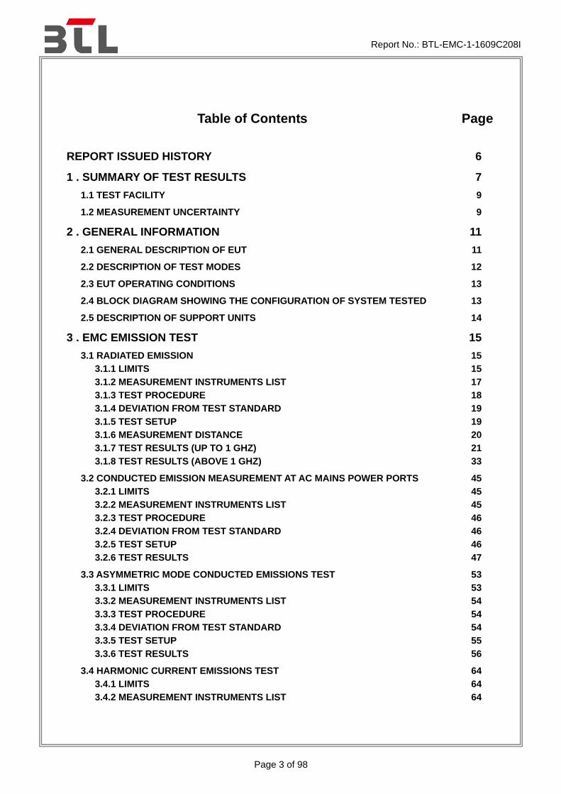
Table of Contents
Page
REPORT ISSUED HISTORY 6
1 . SUMMARY OF TEST RESULTS 7
1.1 TEST FACILITY 9
1.2 MEASUREMENT UNCERTAINTY 9
2 . GENERAL INFORMATION 11
2.1 GENERAL DESCRIPTION OF EUT 11
2.2 DESCRIPTION OF TEST MODES 12
2.3 EUT OPERATING CONDITIONS 13
2.4 BLOCK DIAGRAM SHOWING THE CONFIGURATION OF SYSTEM TESTED 13
2.5 DESCRIPTION OF SUPPORT UNITS 14
3 . EMC EMISSION TEST 15
3.1 RADIATED EMISSION 15
3.1.1 LIMITS 15
3.1.2 MEASUREMENT INSTRUMENTS LIST 17
3.1.3 TEST PROCEDURE 18
3.1.4 DEVIATION FROM TEST STANDARD 19
3.1.5 TEST SETUP 19
3.1.6 MEASUREMENT DISTANCE 20
3.1.7 TEST RESULTS (UP TO 1 GHZ) 21
3.1.8 TEST RESULTS (ABOVE 1 GHZ) 33
3.2 CONDUCTED EMISSION MEASUREMENT AT AC MAINS POWER PORTS 45
3.2.1 LIMITS 45
3.2.2 MEASUREMENT INSTRUMENTS LIST 45
3.2.3 TEST PROCEDURE 46
3.2.4 DEVIATION FROM TEST STANDARD 46
3.2.5 TEST SETUP 46
3.2.6 TEST RESULTS 47
3.3 ASYMMETRIC MODE CONDUCTED EMISSIONS TEST 53
3.3.1 LIMITS 53
3.3.2 MEASUREMENT INSTRUMENTS LIST 54
3.3.3 TEST PROCEDURE 54
3.3.4 DEVIATION FROM TEST STANDARD 54
3.3.5 TEST SETUP 55
3.3.6 TEST RESULTS 56
3.4 HARMONIC CURRENT EMISSIONS TEST 64
3.4.1 LIMITS 64
3.4.2 MEASUREMENT INSTRUMENTS LIST 64

Report No.: BTL-EMC-1-1609C208I
Page 4 of 98
Table of Contents
Page
3.4.3 TEST PROCEDURE 65
3.4.4 DEVIATION FROM TEST STANDARD 65
3.4.5 TEST SETUP 65
3.4.6 TEST RESULTS 66
3.5 VOLTAGE CHANGES, VOLTAGE FLUCTUATIONS AND FLICKER TEST 69
3.5.1 LIMITS 69
3.5.2 MEASUREMENT INSTRUMENTS LIST 69
3.5.3 TEST PROCEDURE 69
3.5.4 DEVIATION FROM TEST STANDARD 69
3.5.5 TESTSETUP 70
3.5.6 TEST RESULTS 71
4 . EMC IMMUNITY TEST 72
4.1 STANDARD COMPLIANCE/SEVERITY LEVEL/CRITERIA 72
4.2 GENERAL PERFORMANCE CRITERIA 74
4.3 ELECTROSTATIC DISCHARGE IMMUNITY TEST (ESD) 75
4.3.1 TEST SPECIFICATION 75
4.3.2 MEASUREMENT INSTRUMENTS 75
4.3.3 TEST PROCEDURE 75
4.3.4 DEVIATION FROM TEST STANDARD 76
4.3.5 TEST SETUP 76
4.3.6 TEST RESULTS 77
4.4 RADIATED, RADIO-FREQUENCY, ELECTROMAGNETIC FIELD IMMUNITY TEST (RS) 81
4.4.1 TEST SPECIFICATION 81
4.4.2 MEASUREMENT INSTRUMENTS 81
4.4.3 TEST PROCEDURE 81
4.4.4 DEVIATION FROM TEST STANDARD 81
4.4.5 TEST SETUP 82
4.4.6 TEST RESULTS 83
4.5 ELECTRICAL FAST TRANSIENT/BURST IMMUNITY TEST (EFT/BURST) 84
4.5.1 TEST SPECIFICATION 84
4.5.2 MEASUREMENT INSTRUMENTS 84
4.5.3 TEST PROCEDURE 84
4.5.4 DEVIATION FROM TEST STANDARD 84
4.5.5 TEST SETUP 85
4.5.6 TEST RESULTS 86
4.6 SURGE IMMUNITY TEST 87
4.6.1 TEST SPECIFICATION 87
4.6.2 MEASUREMENT INSTRUMENTS 87
4.6.3 TEST PROCEDURE 88
4.6.4 DEVIATION FROM TEST STANDARD 88
4.6.5 TEST SETUP 88
4.6.6 TEST RESULTS 89

Report No.: BTL-EMC-1-1609C208I
Page 5 of 98
Table of Contents
Page
4.7 IMMUNITY TO CONDUCTED DISTURBANCES, INDUCED BY RADIO-FREQUENCY
FIELDS TEST (CS) 90
4.7.1 TEST SPECIFICATION 90
4.7.2 MEASUREMENT INSTRUMENTS 90
4.7.3 TEST PROCEDURE 90
4.7.4 DEVIATION FROM TEST STANDARD 90
4.7.5 TEST SETUP 91
4.7.6 TEST RESULTS 92
4.8 POWER FREQUENCY MAGNETIC FIELD IMMUNITY TEST (PFMF) 93
4.8.1 TEST SPECIFICATION 93
4.8.2 MEASUREMENT INSTRUMENTS 93
4.8.3 TEST PROCEDURE 93
4.8.4 DEVIATION FROM TEST STANDARD 93
4.8.5 TEST SETUP 94
4.8.6 TEST RESULTS 95
4.9 VOLTAGE DIPS, SHORT INTERRUPTIONS AND VOLTAGE VARIATIONS IMMUNITY
TEST 96
4.9.1 TEST SPECIFICATION 96
4.9.2 MEASUREMENT INSTRUMENTS 96
4.9.3 TEST PROCEDURE 96
4.9.4 DEVIATION FROM TEST STANDARD 96
4.9.5 TEST SETUP 97
4.9.6 TEST RESULTS 98

Report No.: BTL-EMC-1-1609C208I
Page 6 of 98
REPORT ISSUED HISTORY
Report Version Description Issued Date
R00
Compared with the previous report (BTL-EMC-1-1609C208E), 1.Changed the brand and model name. 2.Changed the applicant, manufacturer, factory‟s information. which does not affect the test results, the rest are kept the same.
May 11, 2020
Remark: For the original report (BTL-EMC-1-1609C208E), the test data, data evaluation and
equipment configuration contained was accredited by the Authority of TAF according to the ISO/IEC 17025 quality assessment standard and technical standard(s).

Report No.: BTL-EMC-1-1609C208I
Page 7 of 98
1. SUMMARY OF TEST RESULTS
Test procedures according to the technical standards:
Emission
Standard(s) Test Item Limit Judgment Remark
EN 55032: 2012+AC:2013
Radiated emissions up to 1 GHz
Class B PASS ------
Radiated emissions above 1 GHz
Class B PASS NOTE (2)
Radiated emissions from FM receivers
------ N/A NOTE (1) NOTE (6)
Conducted emissions AC mains power port
Class B PASS NOTE (7)
Asymmetric mode conducted emissions
AAN ------ PASS
NOTE (1) NOTE (8)
Current Probe ------ N/A
CVP ------ N/A
Conducted differential voltage emissions
------ N/A NOTE (1) NOTE (9)
Standard Test Item Limit Judgment Remark
EN 61000-3-2:2014 Harmonic current emissions Class A PASS NOTE (3)
EN 61000-3-3:2013 Voltage changes, voltage
fluctuations and flicker PASS
Immunity EN 55024: 2010+A1: 2015
Section(s) Test Item Performance
Criterion Judgment Remark
EN 61000-4-2:2009 Electrostatic discharge immunity B PASS
EN 61000-4-3:
2006+A1:2008+A2:2010
Radiated, radio-frequency, electromagnetic field immunity
A PASS
EN 61000-4-4:2012 Electrical fast transient/burst
immunity B PASS
EN 61000-4-5:2014 Surge immunity B/C PASS NOTE (4)
EN 61000-4-6:
2014+AC :2015
Immunity to conducted disturbances, induced by
radio-frequency fields A PASS
EN 61000-4-8:2010 Power frequency magnetic field
immunity A PASS
EN 61000-4-11:2004 Voltage dips, short interruptions and
voltage variations immunity B / C / C PASS NOTE (5)

Report No.: BTL-EMC-1-1609C208I
Page 8 of 98
NOTE: (1) ”N/A” denotes test is not applicable to this device.
(2) The EUT‟s max operating frequency is 166 MHz which does exceed 108 MHz, so the test will be
performed. (3) If the power consumption is less than 75W, there is no limit applied.
(4) Performance Criterion C for signal ports and telecommunication ports.
Performance Criterion B for input d.c. power port and a.c. power ports.
(5) Voltage Dips: >95% reduction – Performance Criterion B
Voltage Dips: 30% reduction – Performance Criterion C
Voltage Interruptions: >95% reduction – Performance Criterion C
(6) If the EUT has FM function the test will be performed. (7) If the EUT has AC power mains port the test will be performed.
(8)
Cable Type Number of pairs Measurement type Procedures
Balanced Unscreened 1 (2 wire) ;2 (4 wire); 3 (6 wire) ;4 (8 wire)
Voltage AAN
Balanced Unscreened See a) Voltage and Current CP+CVP
Screened or Coaxial n/a Voltage AAN
Screened or Coaxial n/a Voltage or Current CP or CVP
Unbalanced cables n/a Voltage and Current CP+CVP
Ports connected to cables with more than 4 balanced pairs or where the port is unable to function correctly when connected through an AAN.
(9) If the EUT has tuner port the test will be performed.
(10) The requirement followed by the client‟s specification.

Report No.: BTL-EMC-1-1609C208I
Page 9 of 98
1.1 TEST FACILITY
The test facilities used to collect the test data in this report is at the location of No.3, Jinshagang 1st Road, Shixia, Dalang Town, Dongguan, Guangdong, China.
1.2 MEASUREMENT UNCERTAINTY
Where relevant, the following measurement uncertainty levels have been estimated for tests performed on the EUT as specified in CISPR 16-4-2, The BTL measurement uncertainty is less than the CISPR 16-4-2 Ucispr requirement. The reported uncertainty of measurement y ± U, where expanded uncertainty U is based on a standard uncertainty multiplied by a coverage factor of k=2, providing a level of confidence of approximately 95%.
A. Conducted emissions AC mains power port measurement:
Test Site Method Measurement Frequency Range U, (dB)
DG-C01 CISPR 150 kHz ~ 30MHz 3.16
B. Conducted disturbance at telecommunication port measurement:
Test Site Method Measurement Frequency Range U, (dB)
DG-C01 CISPR
AAN 50…40dB 3.76
AAN 65…50dB 3.76
AAN 75…60dB 3.76
Capacitive Voltage Probe 3.04
RF Current Probe 2.58
C. Radiated emissions up to 1 GHz measurement:
Test Site Method Measurement Frequency Range Ant. H / V
U, (dB)
DG-CB08 (10m)
CISPR
30MHz ~ 200MHz V 4.66
30MHz ~ 200MHz H 4.64
200MHz ~ 1,000MHz V 4.88
200MHz ~ 1,000MHz H 4.86
D. Radiated emissions above 1 GHz measurement:
Test Site Method Measurement Frequency Range U, (dB)
DG-CB08(3m)
CISPR 1 ~ 6 GHz 4.26
6 ~18 GHz 5.30
E. Harmonic current emissions / Voltage changes, voltage fluctuations and flicker measurement:
Test Site Method Measurement Frequency Range U, (dB)
DG-C01 EN 61000-3-2 EN 61000-3-3
Voltage 0.774
Current 0.782

Report No.: BTL-EMC-1-1609C208I
Page 10 of 98
F. Immunity Measurement:
Test Site Method Measurement Frequency Range U, (dB)
DG-SR02 EN 61000-4-2
Voltage(2kV/4kV/6kV/8kV/15kV/25kV/30kV) 1.0%
Peak Current 6.0%
30/60ns Current 6.0%
Rise time 6.4%
DG-CB05 EN 61000-4-3 80MHz~1GHz 2.175 dB
DG-SR05 EN 61000-4-4
Impulse Voltage 4.0 %
Impulse Rise Time 4.5 %
Impulse duration Time 4.0 %
DG-SR05 EN 61000-4-5
Impulse Voltage 4.0 %
Impulse Rise Time 4.5 %
Impulse duration Time 4.0 %
DG-CB06 EN 61000-4-6 CDN: 150kHz~230MHz 2.509 dB
EM Clamp: 150kHz~230MHz 3.094 dB
DG-SR05 EN 61000-4-8 Magnetic Field Level 3 %
DG-SR05 EN 61000-4-11 Impulse Amplitude 4 %
Timing 3 %
Note: Unless specifically mentioned, the uncertainty of measurement has not been taken into account to declare the compliance or non-compliance to the specification.

Report No.: BTL-EMC-1-1609C208I
Page 11 of 98
2. GENERAL INFORMATION
2.1 GENERAL DESCRIPTION OF EUT
Equipment IP Phone
Brand Name XonTel
Test Model XT-19P
Series Model N/A
Model Difference N/A
Power Source
1# DC Voltage supplied from AC/DC adapter. Manufacturer: SHENZHEN FRECOM ELECTRONICS CO.,LTD. Model: F05L5-050060SPAV L.P.S
2# PoE Supplied
Power Rating 1# I/P: 100-240V~50/60Hz 0.2A O/P: 5V 0.6A 2# PoE 48V
Note: 1. For a more detailed features description, please refer to the manufacturer‟s specifications or the user's
manual.

Report No.: BTL-EMC-1-1609C208I
Page 12 of 98
2.2 DESCRIPTION OF TEST MODES
To investigate the maximum EMI emission characteristics generates from EUT, the test system was pre-scanning tested base on the consideration of following EUT operation mode or test configuration mode which possible have effect on EMI emission level. Each of these EUT operation mode(s) or test configuration mode(s) mentioned above was evaluated respectively.
Pretest Mode Description
Mode 1 Handfree
Mode 2 Handset
Mode 3 Earphone
Mode 4 LAN 100Mbps
Mode 5 LAN 10Mbps
Mode 6 WAN 100Mbps
Mode 7 WAN 10Mbps
For Radiated Test
Final Test Mode Description
Mode 1 Handfree
Mode 2 Handset
Mode 3 Earphone
For Conducted Test
Final Test Mode Description
Mode 1 Handfree
Mode 2 Handset
Mode 3 Earphone
For ISN Test
Final Test Mode Description
Mode 4 LAN 100Mbps
Mode 5 LAN 10Mbps
Mode 6 WAN 100Mbps
Mode 7 WAN 10Mbps
For Harmonics / Flickers Test
Final Test Mode Description
Mode 1 Handfree
Report No.: BTL-EMC-1-1609C208I
Page 13 of 98
For EMS Test
Final Test Mode Description
Mode 1 Handfree
Mode 2 Handset
Mode 3 Earphone
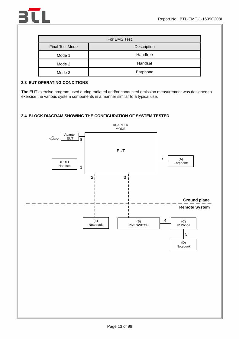
2.3 EUT OPERATING CONDITIONS
The EUT exercise program used during radiated and/or conducted emission measurement was designed to exercise the various system components in a manner similar to a typical use.
2.4 BLOCK DIAGRAM SHOWING THE CONFIGURATION OF SYSTEM TESTED
EUT
6
2
Adapter
EUTAC
100~240V
(B)
PoE SWITCH
(C)
IP Phone
(EUT)
Handset1
4
Ground plane
Remote System
(D)
Notebook
(E)
Notebook
3
ADAPTER
MODE
5
(A)
Earphone
7
Report No.: BTL-EMC-1-1609C208I
Page 14 of 98
EUT
2
(B)
PoE SWITCH
(C)
IP Phone
(EUT)
Handset1
4
Ground plane
Remote System
(D)
Notebook
(E)
Notebook
3
PoE
MODE
5
(A)
Earphone7
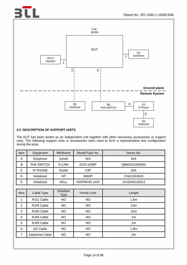
2.5 DESCRIPTION OF SUPPORT UNITS
The EUT has been tested as an independent unit together with other necessary accessories or support units. The following support units or accessories were used to form a representative test configuration during the tests.
Item Equipment Mfr/Brand Model/Type No. Series No.
A Earphone Xontel N/A N/A
B PoE SWITCH D-LINK DGS-1008P QB842D1000045
C IP PHONE Xontel X3P N/A
D Notebook HP 8460P CNU1301BJ3
E Notebook DELL INSPIRON 1420 JX193A01SDC2
Item Cable Type Shielded
Type Ferrite Core Length
1 RJ11 Cable NO NO 1.8m
2 RJ45 Cable NO NO 15m
3 RJ45 Cable NO NO 15m
4 RJ45 Cable NO NO 1m
5 RJ45 Cable NO NO 1m
6 DC Cable NO NO 1.8m
7 Earphone Cable NO NO 2m

Report No.: BTL-EMC-1-1609C208I
Page 15 of 98
3. EMC EMISSION TEST
3.1 RADIATED EMISSION
3.1.1 LIMITS
Class A equipment up to 1000MHz
Table
clause
Frequency
MHz
Measurement Class A limit dB(uV/m)
Distance
m
Detector
type/bandwidth OATS/SAC
A2.1 30-230
10 Quasi peak / 120
kHz
40
230-1000 47
A2.2 30-230
3 50
230-1000 57
Class A equipment above 1000MHz
Table
clause
Frequency
MHz
Measurement Class A limit dB(uV/m)
Distance
m
Detector
type/bandwidth FSOATS
A3.1 1000-3000
3
Average /
1 MHz
56
3000-6000 60
A3.2 1000-3000 Peak /
1 MHz
76
3000-6000 80
Class B equipment up to 1000MHz
Table
clause
Frequency
MHz
Measurement Class B limit dB(uV/m)
Distance
m
Detector
type/bandwidth OATS/SAC
A4.1 30-230
10 Quasi peak / 120
kHz
30
230-1000 37
A4.2 30-230
3 40
230-1000 47
Class B equipment above 1000MHz
Table
clause
Frequency
MHz
Measurement Class B limit dB(uV/m)
Distance
m
Detector
type/bandwidth FSOATS
A5.1 1000-3000
3
Average /
1 MHz
50
3000-6000 54
A5.2 1000-3000 Peak /
1 MHz
70
3000-6000 74

Report No.: BTL-EMC-1-1609C208I
Page 16 of 98
Notes:
(1) The limit for radiated test was performed according to as following: EN 55032
(2) The tighter limit applies at the band edges.
(3) Emission level (dBuV/m)=20log Emission level (uV/m).
(4) The test result calculated as following: Measurement Value = Reading Level + Correct Factor Correct Factor = Antenna Factor + Cable Loss - Amplifier Gain(if use) Margin Level = Measurement Value - Limit Value
Required highest frequency for radiated measurement
Highest internal frequency (Fx) MHz
Highest measured frequency MHz
Fx ≦108 1000
108<Fx ≦500 2000
500< Fx ≦1000 5000
Fx >1000 5th up to a maximum 6 GHz,
Note for FM and TV broadcast receiver, Fx is determined from the highest frequency generated or used excluding the local oscillator and tuned frequencies.

Report No.: BTL-EMC-1-1609C208I
Page 17 of 98
3.1.2 MEASUREMENT INSTRUMENTS LIST
Up to 1GHz:
Item Kind of Equipment Manufacturer Type No. Serial No. Calibrated until
1 Pre-Amplifier Mini-Circuits EMC 9135 980284 Mar. 27, 2017
2 Pre-Amplifier Mini-Circuits EMC 9135 980283 Mar. 27, 2017
3 Trilog-Broadband
Antenna Schwarzbeck VULB9168 586 Feb. 04, 2017
4 Trilog-Broadband
Antenna Schwarzbeck VULB9168 587 Jan. 26, 2017
5 Cable emci LMR-400(5m+
11m+15m) N/A Dec. 31, 2016
6 Cable emci LMR-400(5m+
8m+15m) N/A Dec. 31, 2016
7 Measurement
Software Farad
EZ-EMC Ver.BTL-2ANT-
1 N/A N/A
8 Multi-Device
Controller ETS-Lindgren 2090 N/A N/A
9 Receiver Keysight N9038A MY54450004 Sep. 04, 2017
Remark: “N/A” denotes no model name, no serial no. or no calibration specified.
All calibration period of equipment list is one year.
Above 1GHz:
Item Kind of Equipment Manufacturer Type No. Serial No. Calibrated until
1 Measurement
Software Farad
EZ-EMC Ver.BTL-2ANT-1
N/A N/A
2 Cable emci
SUCOFLEX_15m
_5m(0.01GHz-26.5GHz)
N/A Dec. 27, 2017
3 Multi-Device
Controller ETS-Lindgren 2090 N/A N/A
4 Controller MF MF-7802 MF780208159 N/A
5 Cable emci
SUCOFLEX 102_8m(0.01GHz
-40GHz) N/A Mar. 27, 2017
6 Horn Antenna EMCO 3115 9605-4803 Mar. 27, 2017
Remark: “N/A” denotes no model name, no serial no. or no calibration specified.
All calibration period of equipment list is one year.
Report No.: BTL-EMC-1-1609C208I
Page 18 of 98
3.1.3 TEST PROCEDURE a. a
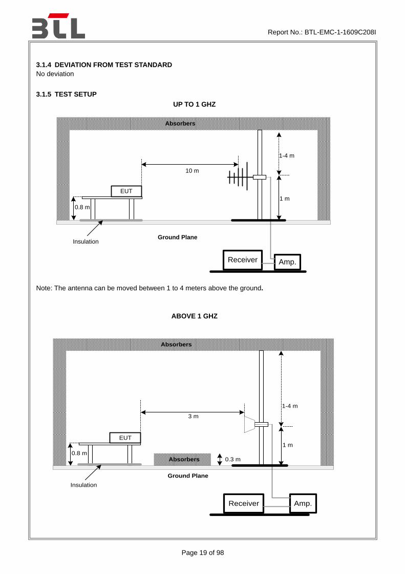
. The measuring distance of 10 m shall be used for measurements. The EUT was placed on the top of a rotating table 0.8 meter above the ground at a 10 meter semi-anechoic chamber. The table was rotated 360 degrees to determine the position of the highest radiation.(below 1GHz).
b. b.
The measuring distance of 3 m shall be used for measurements. The EUT was placed on the top of a rotating table 0.8 meter above the ground at a 10 meter semi-anechoic chamber. The table was rotated 360 degrees to determine the position of the highest radiation.(above 1GHz)
c. c.
The height of the equipment or of the substitution antenna shall be 0.8 m, the height of the test antenna shall vary between 1 m to 4 m. Both horizontal and vertical polarizations of the antenna are set to make the measurement.
d. d.
The initial step in collecting radiated emission data is a receiver peak detector mode pre-scanning the measurement frequency range. Significant peaks are then marked and then Quasi Peak detector mode re-measured.
e. e.
All readings are Peak unless otherwise stated QP in column of Note. Peak denotes that the Peak reading compliance with the QP Limits and then QP Mode measurement didn„t perform. (below 1GHz)
f. f.
All readings are Peak Mode value unless otherwise stated AVG in column of Note. If the Peak Mode Measured value compliance with the Peak Limits and lower than AVG Limits, the EUT shall be deemed to meet both Peak & AVG Limits and then only Peak Mode was measured, but AVG Mode didn„t perform. (above 1GHz)
g. g.
For the actual test configuration, please refer to the related Item - Block Diagram of system tested (please refer to 3.3).
Report No.: BTL-EMC-1-1609C208I
Page 19 of 98
3.1.4 DEVIATION FROM TEST STANDARD
No deviation
3.1.5 TEST SETUP
UP TO 1 GHZ
Amp.
EUT
1-4 m
10 m
Receiver
0.8 m
Absorbers
Ground Plane
1 m
Insulation
Note: The antenna can be moved between 1 to 4 meters above the ground.
ABOVE 1 GHZ
Amp.
EUT
1-4 m
3 m
Receiver
0.8 m
Absorbers
Ground Plane
1 m
Absorbers 0.3 m
Insulation

Report No.: BTL-EMC-1-1609C208I
Page 20 of 98
3.1.6 MEASUREMENT DISTANCE
Report No.: BTL-EMC-1-1609C208I
Page 21 of 98
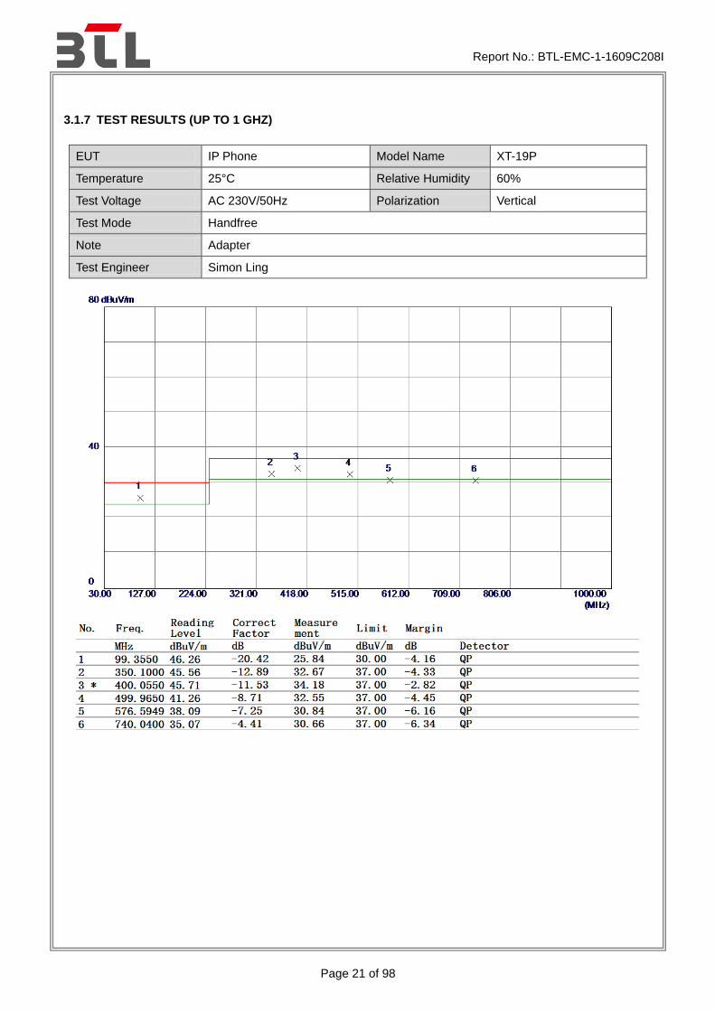
3.1.7 TEST RESULTS (UP TO 1 GHZ)
EUT IP Phone Model Name XT-19P
Temperature 25°C Relative Humidity 60%
Test Voltage AC 230V/50Hz Polarization Vertical
Test Mode Handfree
Note Adapter
Test Engineer Simon Ling

Report No.: BTL-EMC-1-1609C208I
Page 22 of 98
EUT IP Phone Model Name XT-19P
Temperature 25°C Relative Humidity 60%
Test Voltage AC 230V/50Hz Polarization Horizontal
Test Mode Handfree
Note Adapter
Test Engineer Simon Ling

Report No.: BTL-EMC-1-1609C208I
Page 23 of 98
EUT IP Phone Model Name XT-19P
Temperature 25°C Relative Humidity 60%
Test Voltage PoE 48V Polarization Vertical
Test Mode Handfree
Note POE
Test Engineer Simon Ling

Report No.: BTL-EMC-1-1609C208I
Page 24 of 98
EUT IP Phone Model Name XT-19P
Temperature 25°C Relative Humidity 60%
Test Voltage PoE 48V Polarization Horizontal
Test Mode Handfree
Note POE
Test Engineer Simon Ling

Report No.: BTL-EMC-1-1609C208I
Page 25 of 98
EUT IP Phone Model Name XT-19P
Temperature 25°C Relative Humidity 60%
Test Voltage AC 230V/50Hz Polarization Vertical
Test Mode Handset
Note Adapter
Test Engineer Simon Ling

Report No.: BTL-EMC-1-1609C208I
Page 26 of 98
EUT IP Phone Model Name XT-19P
Temperature 25°C Relative Humidity 60%
Test Voltage AC 230V/50Hz Polarization Horizontal
Test Mode Handset
Note Adapter
Test Engineer Simon Ling

Report No.: BTL-EMC-1-1609C208I
Page 27 of 98
EUT IP Phone Model Name XT-19P
Temperature 25°C Relative Humidity 60%
Test Voltage PoE 48V Polarization Vertical
Test Mode Handset
Note POE
Test Engineer Simon Ling

Report No.: BTL-EMC-1-1609C208I
Page 28 of 98
EUT IP Phone Model Name XT-19P
Temperature 25°C Relative Humidity 60%
Test Voltage PoE 48V Polarization Horizontal
Test Mode Handset
Note POE
Test Engineer Simon Ling

Report No.: BTL-EMC-1-1609C208I
Page 29 of 98
EUT IP Phone Model Name XT-19P
Temperature 25°C Relative Humidity 60%
Test Voltage AC 230V/50Hz Polarization Vertical
Test Mode Earphone
Note Adapter
Test Engineer Simon Ling

Report No.: BTL-EMC-1-1609C208I
Page 30 of 98
EUT IP Phone Model Name XT-19P
Temperature 25°C Relative Humidity 60%
Test Voltage AC 230V/50Hz Polarization Horizontal
Test Mode Earphone
Note Adapter
Test Engineer Simon Ling
Report No.: BTL-EMC-1-1609C208I
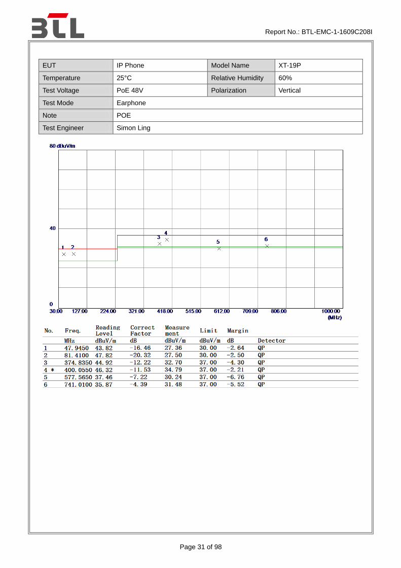
Page 31 of 98
EUT IP Phone Model Name XT-19P
Temperature 25°C Relative Humidity 60%
Test Voltage PoE 48V Polarization Vertical
Test Mode Earphone
Note POE
Test Engineer Simon Ling

Report No.: BTL-EMC-1-1609C208I
Page 32 of 98
EUT IP Phone Model Name XT-19P
Temperature 25°C Relative Humidity 60%
Test Voltage PoE 48V Polarization Horizontal
Test Mode Earphone
Note POE
Test Engineer Simon Ling

Report No.: BTL-EMC-1-1609C208I
Page 33 of 98
3.1.8 TEST RESULTS (ABOVE 1 GHZ)
EUT IP Phone Model Name XT-19P
Temperature 25°C Relative Humidity 45%
Test Voltage AC 230V/50Hz Polarization Vertical
Test Mode Handfree
Note Adapter
Test Engineer Simon Ling

Report No.: BTL-EMC-1-1609C208I
Page 34 of 98
EUT IP Phone Model Name XT-19P
Temperature 25°C Relative Humidity 45%
Test Voltage AC 230V/50Hz Polarization Horizontal
Test Mode Handfree
Note Adapter
Test Engineer Simon Ling
Report No.: BTL-EMC-1-1609C208I
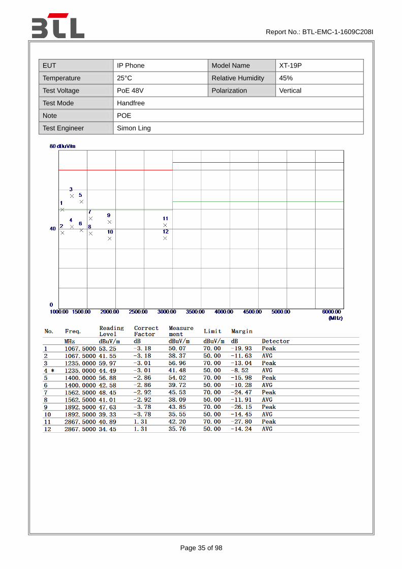
Page 35 of 98
EUT IP Phone Model Name XT-19P
Temperature 25°C Relative Humidity 45%
Test Voltage PoE 48V Polarization Vertical
Test Mode Handfree
Note POE
Test Engineer Simon Ling

Report No.: BTL-EMC-1-1609C208I
Page 36 of 98
EUT IP Phone Model Name XT-19P
Temperature 25°C Relative Humidity 45%
Test Voltage PoE 48V Polarization Horizontal
Test Mode Handfree
Note POE
Test Engineer Simon Ling

Report No.: BTL-EMC-1-1609C208I
Page 37 of 98
EUT IP Phone Model Name XT-19P
Temperature 25°C Relative Humidity 45%
Test Voltage AC 230V/50Hz Polarization Vertical
Test Mode Handset
Note Adapter
Test Engineer Simon Ling

Report No.: BTL-EMC-1-1609C208I
Page 38 of 98
EUT IP Phone Model Name XT-19P
Temperature 25°C Relative Humidity 45%
Test Voltage AC 230V/50Hz Polarization Horizontal
Test Mode Handset
Note Adapter
Test Engineer Simon Ling

Report No.: BTL-EMC-1-1609C208I
Page 39 of 98
EUT IP Phone Model Name XT-19P
Temperature 25°C Relative Humidity 45%
Test Voltage PoE 48V Polarization Vertical
Test Mode Handset
Note POE
Test Engineer Simon Ling

Report No.: BTL-EMC-1-1609C208I
Page 40 of 98
EUT IP Phone Model Name XT-19P
Temperature 25°C Relative Humidity 45%
Test Voltage PoE 48V Polarization Horizontal
Test Mode Handset
Note POE
Test Engineer Simon Ling

Report No.: BTL-EMC-1-1609C208I
Page 41 of 98
EUT IP Phone Model Name XT-19P
Temperature 25°C Relative Humidity 45%
Test Voltage AC 230V/50Hz Polarization Vertical
Test Mode Earphone
Note Adapter
Test Engineer Simon Ling

Report No.: BTL-EMC-1-1609C208I
Page 42 of 98
EUT IP Phone Model Name XT-19P
Temperature 25°C Relative Humidity 45%
Test Voltage AC 230V/50Hz Polarization Horizontal
Test Mode Earphone
Note Adapter
Test Engineer Simon Ling
Report No.: BTL-EMC-1-1609C208I
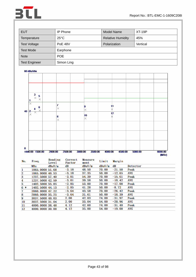
Page 43 of 98
EUT IP Phone Model Name XT-19P
Temperature 25°C Relative Humidity 45%
Test Voltage PoE 48V Polarization Vertical
Test Mode Earphone
Note POE
Test Engineer Simon Ling

Report No.: BTL-EMC-1-1609C208I
Page 44 of 98
EUT IP Phone Model Name XT-19P
Temperature 25°C Relative Humidity 45%
Test Voltage PoE 48V Polarization Horizontal
Test Mode Earphone
Note POE
Test Engineer Simon Ling

Report No.: BTL-EMC-1-1609C208I
Page 45 of 98
3.2 CONDUCTED EMISSION MEASUREMENT AT AC MAINS POWER PORTS
3.2.1 LIMITS
Requirements for conducted emissions from AC mains power ports of Class A equipment
Table
clause
Frequency Range
MHz
Coupling
Device
Detector
Type /
bandwidth
Class A Limits
(dB(μV) )
A8.1 0.15 - 0.5
AMN Quasi Peak / 9
kHz
79
0.5 - 30 73
A8.2 0.15 - 0.5
AMN Average /
9 kHz
66
0.5 - 30 60
Requirements for conducted emissions from AC mains power ports of Class B equipment
Table
clause
Frequency Range
MHz
Coupling
Device
Detector
Type /
bandwidth
Class B Limits
(dB(μV) )
A9.1
0.15 - 0.5
AMN Quasi Peak / 9
kHz
66-56
0.5 - 5 56
5 - 30 60
A9.2
0.15 - 0.5
AMN Average /
9 kHz
56-46
0.5 - 5 46
5 - 30 50
NOTE: (1) The test result calculated as following:
Measurement Value = Reading Level + Correct Factor Correct Factor = Insertion Loss + Cable Loss + Attenuator Factor(if use) Margin Level = Measurement Value – Limit Value
3.2.2 MEASUREMENT INSTRUMENTS LIST
Item Kind of Equipment Manufacturer Type No. Serial No. Calibrated until
1 Measurement
Software Farad
EZ-EMC Ver.NB-03A1
-01 N/A N/A
2 50Ω Terminator SHX TF2-3G-A 08122901 Mar. 27, 2017
3 TWO-LINE
V-NETWORK R&S ENV216 100526 Mar. 27, 2017
4 EMI Test Receiver R&S ESR3 101862 Sep. 04, 2017
5 Artificial-Mains
Network SCHWARZBECK NSLK 8127 8127685 Sep. 04, 2017
6 Cable N/A RG400 12m N/A Mar. 10, 2017
Remark: “N/A” denotes no model name, no serial no. or no calibration specified.
All calibration period of equipment list is one year.

Report No.: BTL-EMC-1-1609C208I
Page 46 of 98
3.2.3 TEST PROCEDURE
a. The EUT was placed 0.8 meters from the horizontal ground plane with EUT being connected to the
power mains through a line impedance stabilization network (LISN). All other support equipments
powered from additional LISN(s). The LISN provide 50 Ohm/ 50uH of coupling impedance for the
measuring instrument.
b. Interconnecting cables that hang closer than 40 cm to the ground plane shall be folded back and forth in the center forming a bundle 30 to 40 cm long.
c. I/O cables that are not connected to a peripheral shall be bundled in the center. The end of the cable may be terminated, if required, using the correct terminating impedance. The overall length shall not exceed 1 m.
d. LISN at least 80 cm from nearest part of EUT chassis.
e. For the actual test configuration, please refer to the related Item –EUT Test Photos.
3.2.4 DEVIATION FROM TEST STANDARD
No deviation
3.2.5 TEST SETUP

Report No.: BTL-EMC-1-1609C208I
Page 47 of 98
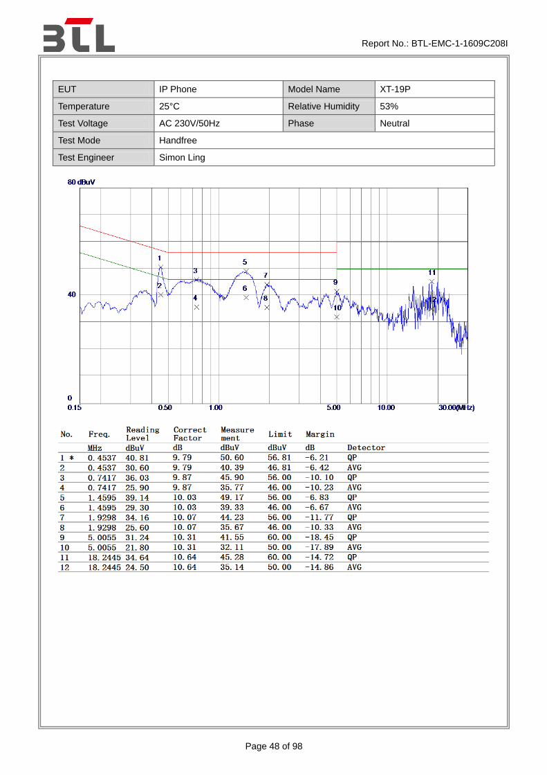
3.2.6 TEST RESULTS
EUT IP Phone Model Name XT-19P
Temperature 25°C Relative Humidity 53%
Test Voltage AC 230V/50Hz Phase Line
Test Mode Handfree
Test Engineer Simon Ling
Report No.: BTL-EMC-1-1609C208I
Page 48 of 98
EUT IP Phone Model Name XT-19P
Temperature 25°C Relative Humidity 53%
Test Voltage AC 230V/50Hz Phase Neutral
Test Mode Handfree
Test Engineer Simon Ling

Report No.: BTL-EMC-1-1609C208I
Page 49 of 98
EUT IP Phone Model Name XT-19P
Temperature 25°C Relative Humidity 53%
Test Voltage AC 230V/50Hz Phase Line
Test Mode Handset
Test Engineer Simon Ling

Report No.: BTL-EMC-1-1609C208I
Page 50 of 98
EUT IP Phone Model Name XT-19P
Temperature 25°C Relative Humidity 53%
Test Voltage AC 230V/50Hz Phase Neutral
Test Mode Handset
Test Engineer Simon Ling

Report No.: BTL-EMC-1-1609C208I
Page 51 of 98
EUT IP Phone Model Name XT-19P
Temperature 25°C Relative Humidity 53%
Test Voltage AC 230V/50Hz Phase Line
Test Mode Earphone
Test Engineer Simon Ling

Report No.: BTL-EMC-1-1609C208I
Page 52 of 98
EUT IP Phone Model Name XT-19P
Temperature 25°C Relative Humidity 53%
Test Voltage AC 230V/50Hz Phase Neutral
Test Mode Earphone
Test Engineer Simon Ling

Report No.: BTL-EMC-1-1609C208I
Page 53 of 98
3.3 ASYMMETRIC MODE CONDUCTED EMISSIONS TEST 3.3.1 LIMITS
Requirements for asymmetric mode conducted emissions from Class A equipment
Table
clause
Frequency
range
MHz
Coupling device Detector type
/ Bandwidth
Class A
voltage limits
dB(μV)
Class A
current limits
dB(μV)
A10.1
0.15 - 0.5 AAN
Quasi Peak / 9 kHz
97 - 87
n/a 0.5 - 30 87
0.15 - 0.5 AAN
Average / 9 kHz
84- 74
0.5 - 30 74
A10.2
0.15 - 0.5 CVP and current probe
Quasi Peak / 9 kHz
97 - 87 53 -43
0.5 - 30 87 43
0.15 - 0.5 CVP and current probe
Average / 9 kHz
84- 74 40 -30
0.5 - 30 74 30
A10.3
0.15 - 0.5 Current probe
Quasi Peak / 9 kHz
n/a
53 -43
0.5 - 30 43
0.15 - 0.5 Current probe
Average / 9 kHz
40 -30
0.5 - 30 30
Requirements for asymmetric mode conducted emissions from Class B equipment
Table
clause
Frequency
range
MHz
Coupling device Detector type
/ Bandwidth
Class B
voltage limits
dB(μV)
Class B
current limits
dB(μV)
A11.1
0.15 - 0.5 AAN
Quasi Peak / 9 kHz
84 - 74
n/a 0.5 - 30 74
0.15 - 0.5 AAN
Average / 9 kHz
74- 64
0.5 - 30 64
A11.2
0.15 - 0.5 CVP and current probe
Quasi Peak / 9 kHz
84 - 74 40 -30
0.5 - 30 74 30
0.15 - 0.5 CVP and current probe
Average / 9 kHz
74- 64 30 -20
0.5 - 30 64 20
A11.3
0.15 - 0.5 Current probe
Quasi Peak / 9 kHz
n/a
40 -30
0.5 - 30 30
0.15 - 0.5 Current probe
Average / 9 kHz
30 -20
0.5 - 30 20
NOTE: (1) The test result calculated as following:
Measurement Value = Reading Level + Correct Factor Correct Factor = Insertion Loss + Cable Loss + Attenuator Factor(if use) Margin Level = Measurement Value – Limit Value

Report No.: BTL-EMC-1-1609C208I
Page 54 of 98
3.3.2 MEASUREMENT INSTRUMENTS LIST
Item Kind of Equipment Manufacturer Type No. Serial No. Calibrated until
1 ISN FCC
F-070306-1057-1-09
100362 Mar. 27, 2017
2 Measurement
Software Farad
EZ-EMC Ver.NB-03A1
-01 N/A N/A
3 50Ω Terminator SHX TF2-3G-A 08122901 Mar. 27, 2017
4 TWO-LINE V-NETWORK
R&S ENV216 100526 Mar. 27, 2017
5 EMI Test Receiver R&S ESR3 101862 Sep. 04, 2017
6 Artificial-Mains Network
SCHWARZBECK NSLK 8127 8127685 Sep. 04, 2017
7 Cable N/A RG400 12m N/A Mar. 10, 2017
Remark: “N/A” denotes no model name, no serial No. or no calibration specified.
All calibration period of equipment list is one year.
3.3.3 TEST PROCEDURE
a. The EUT was placed 0.8 meters from the horizontal ground plane with EUT being connected to the
power mains through a line impedance stabilization network (LISN). All other support equipment
powered from additional LISN(s). The LISN provide 50 Ohm/ 50uH of coupling impedance for the
measuring instrument.
b. Interconnecting cables that hang closer than 40 cm to the ground plane shall be folded back and forth in the center forming a bundle 30 to 40 cm long.
c. I/O cables that are not connected to a peripheral shall be bundled in the center. The end of the cable may be terminated, if required, using the correct terminating impedance. The overall length shall not exceed 1 m.
d. For the actual test configuration, please refer to the related Item –EUT Test Photos.
e. AAN, CP or CVP at least 80 cm from nearest part of EUT chassis.
NOTE:
f. The communication function of EUT was executed and AAN was connected between EUT and associated equipment and the AAN was connected directly to reference ground plane. Measure the voltage at the measurement port of the AAN Correct the measured voltage by adding the AAN voltage division factor Compare the corrected voltage with the limit(For AAN)
g Measure the current with a current probe and compare to the current limit(For CP) h The current shall be measured with the current probe and the results compared with the
current limits. The voltage measured shall be corrected at each frequency of interest as follows: - if the current margin with respect to the current limit is ≤6 dB, the actual current margin shall be subtracted from the measured voltage; -if the current margin with respect to the current limit is >6 dB, 6 dB shall be subtracted from the measured voltage. The adjusted voltage shall be compared with the applicable voltage limit. Both the measured current and the corrected voltage shall be below the applicable current and voltage limits at all frequencies for the EUT to be deemed compliant with this publication.(For CVP)
3.3.4 DEVIATION FROM TEST STANDARD
No deviation

Report No.: BTL-EMC-1-1609C208I
Page 55 of 98
3.3.5 TEST SETUP
a) Cable Type: Balanced Unscreened, Screened or Coaxial
CDN/AAN
EUT Test Receiver40 cm
Horizontal Reference Ground Plane
Vertical Reference Ground Plane
AE
80 cm
80 cm
Insulation
b) Cable Type: Screened or Coaxial
Current Probe
EUT Test Receiver40 cm
Horizontal Reference Ground Plane
Vertical Reference Ground Plane
AE
80 cm
80 cm
Insulation
c) Cable Type: Balanced Unscreened, Unbalanced
Report No.: BTL-EMC-1-1609C208I
Page 56 of 98
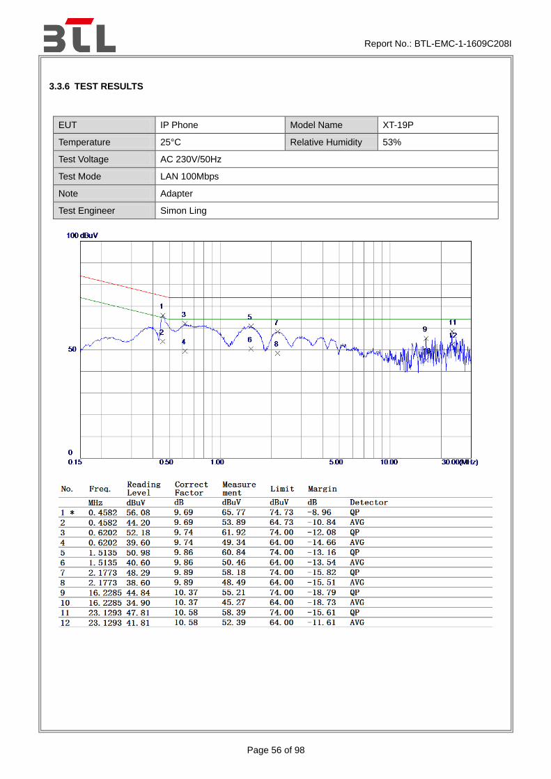
3.3.6 TEST RESULTS
EUT IP Phone Model Name XT-19P
Temperature 25°C Relative Humidity 53%
Test Voltage AC 230V/50Hz
Test Mode LAN 100Mbps
Note Adapter
Test Engineer Simon Ling
Report No.: BTL-EMC-1-1609C208I
Page 57 of 98
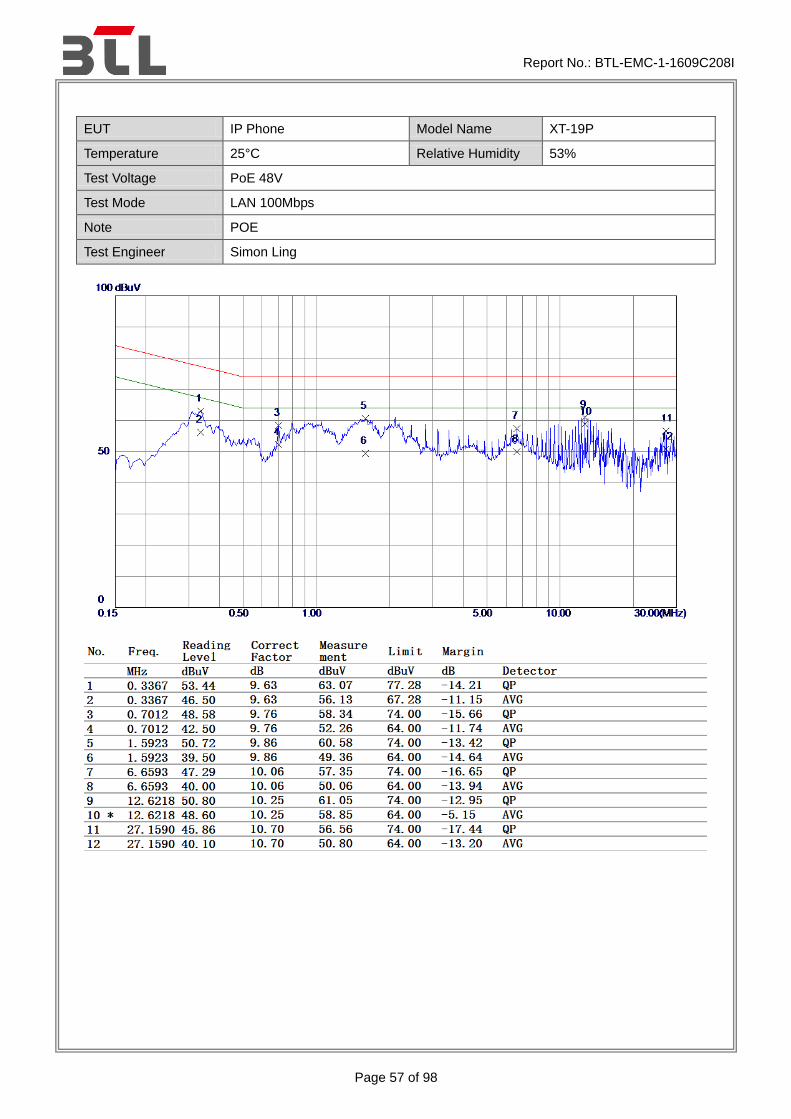
EUT IP Phone Model Name XT-19P
Temperature 25°C Relative Humidity 53%
Test Voltage PoE 48V
Test Mode LAN 100Mbps
Note POE
Test Engineer Simon Ling
Report No.: BTL-EMC-1-1609C208I
Page 58 of 98
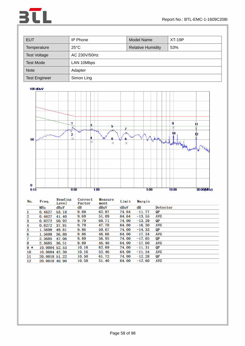
EUT IP Phone Model Name XT-19P
Temperature 25°C Relative Humidity 53%
Test Voltage AC 230V/50Hz
Test Mode LAN 10Mbps
Note Adapter
Test Engineer Simon Ling

Report No.: BTL-EMC-1-1609C208I
Page 59 of 98
EUT IP Phone Model Name XT-19P
Temperature 25°C Relative Humidity 53%
Test Voltage PoE 48V
Test Mode LAN 10Mbps
Note POE
Test Engineer Simon Ling

Report No.: BTL-EMC-1-1609C208I
Page 60 of 98
EUT IP Phone Model Name XT-19P
Temperature 25°C Relative Humidity 53%
Test Voltage AC 230V/50Hz
Test Mode WAN 100Mbps
Note Adapter
Test Engineer Simon Ling
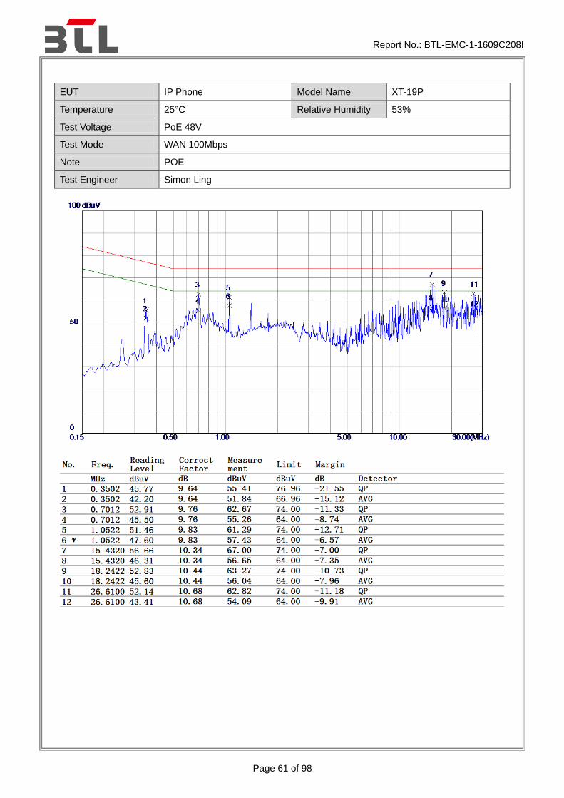
Report No.: BTL-EMC-1-1609C208I
Page 61 of 98
EUT IP Phone Model Name XT-19P
Temperature 25°C Relative Humidity 53%
Test Voltage PoE 48V
Test Mode WAN 100Mbps
Note POE
Test Engineer Simon Ling

Report No.: BTL-EMC-1-1609C208I
Page 62 of 98
EUT IP Phone Model Name XT-19P
Temperature 25°C Relative Humidity 53%
Test Voltage AC 230V/50Hz
Test Mode WAN 10Mbps
Note Adapter
Test Engineer Simon Ling

Report No.: BTL-EMC-1-1609C208I
Page 63 of 98
EUT IP Phone Model Name XT-19P
Temperature 25°C Relative Humidity 53%
Test Voltage PoE 48V
Test Mode WAN 10Mbps
Note POE
Test Engineer Simon Ling

Report No.: BTL-EMC-1-1609C208I
Page 64 of 98
3.4 HARMONIC CURRENT EMISSIONS TEST
3.4.1 LIMITS
EN 61000-3-2
Equipment Category
Harmonic Order
Max. Permissible Harmonic Current
Equipment Category
Harmonic Order
Max. Permissible Harmonic Current
n A n A mA/w
Class A
Odd Harmonics
Class D
Odd Harmonics only
3 2.30 3 2.30 3.4
5 1.14 5 1.14 1.9
7 0.77 7 0.77 1.0
9 0.40 9 0.40 0.5
11 0.33 11 0.33 0.35
13 0.21 13 0.21 0.30
15n39 0.15 x 15/n 15n39 0.15 x 15/n 3.85/n
Even Harmonics
2 1.08
4 0.43
6 0.30
8n40 0.23 x 8/n
3.4.2 MEASUREMENT INSTRUMENTS LIST
Item Kind of Equipment Manufacturer Type No. Serial No. Calibrated until
1 Harmonics and Flicker Analyzer
California Instruments
PACS-1 72344 Jul. 26, 2017
2 3KVA AC Power
source California
Instruments 3001ix 56309 Jul. 26, 2017
3 Measurement Software
California CTS4.0
Version 4.9 N/A N/A
Remark: “N/A” denotes no model name, no serial No. or no calibration specified.
All calibration period of equipment list is one year.

Report No.: BTL-EMC-1-1609C208I
Page 65 of 98
3.4.3 TEST PROCEDURE
a. The EUT was placed on the top of a wooden table 0.8 meters above the ground and operated to produce the maximum harmonic components under normal operating conditions.
b. The classification of EUT is according to of EN 61000-3-2.The EUT is classified as follows:
Class A: Balanced three-phase equipment, Household appliances excluding equipment as Class D, Tools excluding portable tools, Dimmers for incandescent lamps, audio equipment, equipment not specified in one of the three other classes.
Class B: Portable tools; Arc welding equipment which is not professional equipment.
Class C: Lighting equipment.
Class D: Equipment having a specified power less than or equal to600 W of the following types: Personal computers and personal computer monitors and television receivers.
c. The correspondent test program of test instrument to measure the current harmonics emanated from EUT is chosen. The measure time shall be not less than the time necessary for the EUT to be exercised.
3.4.4 DEVIATION FROM TEST STANDARD
No deviation
3.4.5 TEST SETUP
EUT
To AC Mains
Power Supply
Non-Metallic Table
Power Analyzer &
Power Source
Voltage Supply
To EUT

Report No.: BTL-EMC-1-1609C208I
Page 66 of 98
3.4.6 TEST RESULTS
Harmonic - Class A
EUT IP Phone Model Name XT-19P
Temperature 25°C Relative Humidity 55%
Test Voltage AC 230V/50Hz
Test Mode Handfree
Current & voltage waveforms
0
- 3 0 0
- 2 0 0
- 1 0 0
0
1 0 0
2 0 0
3 0 0
Cu
rr
en
t
(A
mp
s)
Vo
lt
ag
e
(V
ol
ts
)
Harmonics and Class A limit line European Limits
0 . 0
0 . 5
1 . 0
1 . 5
2 . 0
2 . 5
3 . 0
3 . 5
Cu
rr
en
t
RM
S(
Am
ps
)
H a r m o n i c #4 8 1 2 1 6 2 0 2 4 2 8 3 2 3 6 4 0
Test result: Pass Worst harmonic was #0 with 0.0% of the limit.

Report No.: BTL-EMC-1-1609C208I
Page 67 of 98
Current Test Result Summary (Run time)
EUT IP Phone Model Name XT-19P
Temperature 25°C Relative Humidity 55%
Test Voltage AC 230V/50Hz
Test Mode Handfree
Highest parameter values during test:
V_RMS (Volts): 230.05 Frequency(Hz): 50.00 I_Peak (Amps): 0.018 I_RMS (Amps): 0.003 I_Fund (Amps): 0.001 Crest Factor: 6.830 Power (Watts): 0.2 Power Factor: 0.379
Harm#Harms(avg) 100%Limit %of Limit Harms(max) 150%Limit %of Limit Status 2 0.001 1.080 N/A 0.001 1.620 N/A Pass 3 0.002 2.300 N/A 0.002 3.450 N/A Pass 4 0.001 0.430 N/A 0.001 0.645 N/A Pass 5 0.001 1.140 N/A 0.001 1.710 N/A Pass 6 0.000 0.300 N/A 0.000 0.450 N/A Pass 7 0.000 0.770 N/A 0.000 1.155 N/A Pass 8 0.000 0.230 N/A 0.000 0.345 N/A Pass 9 0.000 0.400 N/A 0.000 0.600 N/A Pass 10 0.000 0.184 N/A 0.000 0.276 N/A Pass 11 0.000 0.330 N/A 0.000 0.495 N/A Pass 12 0.000 0.153 N/A 0.000 0.230 N/A Pass 13 0.000 0.210 N/A 0.000 0.315 N/A Pass 14 0.000 0.131 N/A 0.000 0.197 N/A Pass 15 0.000 0.150 N/A 0.000 0.225 N/A Pass 16 0.000 0.115 N/A 0.000 0.173 N/A Pass 17 0.000 0.132 N/A 0.000 0.198 N/A Pass 18 0.000 0.102 N/A 0.000 0.153 N/A Pass 19 0.000 0.118 N/A 0.000 0.178 N/A Pass 20 0.000 0.092 N/A 0.000 0.138 N/A Pass 21 0.000 0.107 N/A 0.000 0.161 N/A Pass 22 0.000 0.084 N/A 0.000 0.125 N/A Pass 23 0.000 0.098 N/A 0.000 0.147 N/A Pass 24 0.000 0.077 N/A 0.000 0.115 N/A Pass 25 0.000 0.090 N/A 0.000 0.135 N/A Pass 26 0.000 0.071 N/A 0.000 0.107 N/A Pass 27 0.000 0.083 N/A 0.000 0.125 N/A Pass 28 0.000 0.066 N/A 0.000 0.099 N/A Pass 29 0.000 0.078 N/A 0.000 0.116 N/A Pass 30 0.000 0.061 N/A 0.000 0.092 N/A Pass 31 0.000 0.073 N/A 0.000 0.109 N/A Pass 32 0.000 0.058 N/A 0.000 0.086 N/A Pass 33 0.000 0.068 N/A 0.000 0.102 N/A Pass 34 0.000 0.054 N/A 0.000 0.081 N/A Pass 35 0.000 0.064 N/A 0.000 0.096 N/A Pass 36 0.000 0.051 N/A 0.000 0.077 N/A Pass 37 0.000 0.061 N/A 0.000 0.091 N/A Pass 38 0.000 0.048 N/A 0.000 0.073 N/A Pass 39 0.000 0.058 N/A 0.000 0.087 N/A Pass 40 0.000 0.046 N/A 0.000 0.069 N/A Pass
Report No.: BTL-EMC-1-1609C208I
Page 68 of 98
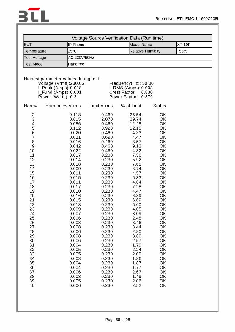
Voltage Source Verification Data (Run time)
EUT IP Phone Model Name XT-19P
Temperature 25°C Relative Humidity 55%
Test Voltage AC 230V/50Hz
Test Mode Handfree
Highest parameter values during test:
Voltage (Vrms): 230.05 Frequency(Hz): 50.00 I_Peak (Amps): 0.018 I_RMS (Amps): 0.003 I_Fund (Amps): 0.001 Crest Factor: 6.830 Power (Watts): 0.2 Power Factor: 0.379
Harm# Harmonics V-rms Limit V-rms % of Limit Status 2 0.118 0.460 25.54 OK 3 0.615 2.070 29.74 OK 4 0.056 0.460 12.25 OK 5 0.112 0.920 12.15 OK 6 0.020 0.460 4.33 OK 7 0.031 0.690 4.47 OK 8 0.016 0.460 3.57 OK 9 0.042 0.460 9.12 OK 10 0.022 0.460 4.82 OK 11 0.017 0.230 7.58 OK 12 0.014 0.230 5.92 OK 13 0.018 0.230 7.65 OK 14 0.009 0.230 3.74 OK 15 0.011 0.230 4.57 OK 16 0.015 0.230 6.33 OK 17 0.011 0.230 4.64 OK 18 0.017 0.230 7.28 OK 19 0.010 0.230 4.47 OK 20 0.016 0.230 6.89 OK 21 0.015 0.230 6.69 OK 22 0.013 0.230 5.60 OK 23 0.009 0.230 4.05 OK 24 0.007 0.230 3.09 OK 25 0.006 0.230 2.48 OK 26 0.008 0.230 3.46 OK 27 0.008 0.230 3.44 OK 28 0.006 0.230 2.80 OK 29 0.008 0.230 3.60 OK 30 0.006 0.230 2.57 OK 31 0.004 0.230 1.79 OK 32 0.005 0.230 2.24 OK 33 0.005 0.230 2.09 OK 34 0.003 0.230 1.36 OK 35 0.004 0.230 1.87 OK 36 0.004 0.230 1.77 OK 37 0.006 0.230 2.67 OK 38 0.003 0.230 1.49 OK 39 0.005 0.230 2.06 OK 40 0.006 0.230 2.52 OK
Report No.: BTL-EMC-1-1609C208I
Page 69 of 98
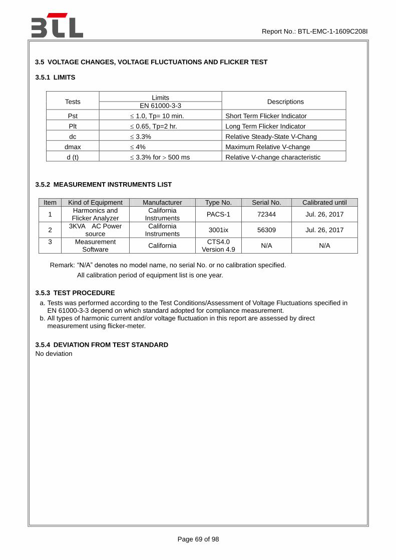
3.5 VOLTAGE CHANGES, VOLTAGE FLUCTUATIONS AND FLICKER TEST
3.5.1 LIMITS
Tests Limits
Descriptions EN 61000-3-3
Pst 1.0, Tp= 10 min. Short Term Flicker Indicator
Plt 0.65, Tp=2 hr. Long Term Flicker Indicator
dc 3.3% Relative Steady-State V-Chang
dmax 4% Maximum Relative V-change
d (t) 3.3% for 500 ms Relative V-change characteristic
3.5.2 MEASUREMENT INSTRUMENTS LIST
Item Kind of Equipment Manufacturer Type No. Serial No. Calibrated until
1 Harmonics and Flicker Analyzer
California Instruments
PACS-1 72344 Jul. 26, 2017
2 3KVA AC Power
source California
Instruments 3001ix 56309 Jul. 26, 2017
3 Measurement Software
California CTS4.0
Version 4.9 N/A N/A
Remark: “N/A” denotes no model name, no serial No. or no calibration specified.
All calibration period of equipment list is one year.
3.5.3 TEST PROCEDURE
a. Tests was performed according to the Test Conditions/Assessment of Voltage Fluctuations specified in EN 61000-3-3 depend on which standard adopted for compliance measurement.
b. All types of harmonic current and/or voltage fluctuation in this report are assessed by direct measurement using flicker-meter.
3.5.4 DEVIATION FROM TEST STANDARD
No deviation

Report No.: BTL-EMC-1-1609C208I
Page 70 of 98
3.5.5 TESTSETUP
EUT
To AC Mains
Power Supply
Non-Metallic Table
Power Analyzer &
Power Source
Voltage Supply
To EUT

Report No.: BTL-EMC-1-1609C208I
Page 71 of 98
3.5.6 TEST RESULTS
EUT IP Phone Model Name XT-19P
Temperature 25°C Relative Humidity 55%
Test Voltage AC 230V/50Hz
Test Mode Handfree
Psti and limit line European Limits
0 . 2 5
0 . 5 0
0 . 7 5
1 . 0 0
Ps
t
16
:5
7:
16
Plt and limit line
0 . 2 5
0 . 5 0
Pl
t
16
:5
7:
16
Parameter values recorded during the test: Vrms at the end of test (Volt):230.02 Highest dt (%): 0.00 Test limit (%): N/A N/A T-max (mS): 0 Test limit (mS): 500.0 Pass Highest dc (%): 0.00 Test limit (%): 3.30 Pass Highest dmax (%): -0.04 Test limit (%): 4.00 Pass Highest Pst (10 min. period): 0.279 Test limit: 1.000 Pass Highest Plt (2 hr. period): 0.122 Test limit: 0.650 Pass

Report No.: BTL-EMC-1-1609C208I
Page 72 of 98
4. EMC IMMUNITY TEST
4.1 STANDARD COMPLIANCE/SEVERITY LEVEL/CRITERIA
Tests
Standard No.
Test Specification Level /
Test Mode Test Ports Criteria
Electrostatic discharge EN 61000-4-2 (ESD)
±8 kV air discharge
±4 kV contact discharge
(Direct Mode)
Enclosure B
±4kV HCP discharge
±4kV VCP discharge
(Indirect Mode)
Enclosure B
Radiated, radio-frequency, electromagnetic field immunity EN 61000-4-3 (RS)
80 MHz to 1000 MHz
3V/m(unmodulated, r.m.s),
1 kHz, 80%,
AM modulated
Enclosure A
Electrical fast transient/burst immunity EN 61000-4-4 (EFT/Burst)
±0.5kV(peak)
5/50ns Tr/Th
5kHz Repetition Frequency
(100kHz Repetition Frequency for
xDSL equipment )
Signal ports and
telecommunication ports
(Only applicable to cable
length>3 m)
B
±0.5kV(peak)
5/50ns Tr/Th
5kHz Repetition Frequency
DC Power Ports B
±1 kV(peak)
5/50ns Tr/Th
5kHz Repetition Frequency
AC Power Ports B
Surge immunity EN 61000-4-5 (Surges)
±1 kV(peak)
10/700 Tr/Th μs(NOTE)
(without primary protection)
Signal ports and
telecommunication ports
(applicable only to ports
connect directly to
outdoor cables)
C
±4 kV(peak)
10/700 Tr/Th μs(NOTE)
(with primary protectors fitted)
C
±0.5 kV(peak)
1.2/50(8/20) Tr/Th μs
DC Power Ports
(applicable only to ports
connect directly to
outdoor cables)
B
±1 kV(peak)
1.2/50(8/20) Tr/Th μs
(line to line)
AC Power Ports
B
±2 kV(peak)
1.2/50(8/20) Tr/Th μs
(line to earth or ground)
B

Report No.: BTL-EMC-1-1609C208I
Page 73 of 98
Immunity to conducted disturbances, induced by radio-frequency fields
EN 61000-4-6
(Injected Current)
0.15 MHz to 80 MHz
3V(unmodulated, r.m.s), 1kHz 80%,
AM
150 source impedance
Signal ports and
telecommunication ports
(Only applicable to cable
length>3 m)
A
0.15 MHz to 80 MHz
3V(unmodulated, r.m.s), 1kHz 80%,
AM
150 source impedance
DC Power Ports A
0.15 MHz to 80 MHz
3V(unmodulated, r.m.s), 1kHz 80%,
AM
150 source impedance
AC Power Ports A
Power frequency magnetic field immunity EN 61000-4-8 (PFMF)
50 Hz or 60Hz, 1A/m(r.m.s)μs Enclosure A
Voltage dips, short interruptions and voltage variations immunity EN 61000-4-11 (Voltage Interruption/Dips)
Voltage reduction>95%
0.5 period
Voltage reduction 30%
25 periods
Voltage reduction>95%
250 periods
AC Power Ports
B
C
C
Note. Where the coupling network for the 10/700 μs waveform affects the functioning of high speed data ports, the test shall be carried out using a 1,2/50 (8/20) μs waveform and appropriate coupling network.

Report No.: BTL-EMC-1-1609C208I
Page 74 of 98
4.2 GENERAL PERFORMANCE CRITERIA
According to EN55024 standard, the general performance criteria as following:
Criterion A
The equipment shall continue to operate as intended without operator intervention. No
degradation of performance or loss of function is allowed below a performance level
specified by the manufacturer when the equipment is used as intended. The
performance level may be replaced by a permissible loss of performance.
If the minimum performance level or the permissible performance loss is not specified by
the manufacturer, then either of these may be derived from the product description and
documentation, and by what the user product description and documentation, and by
what the user may reasonably expect from the equipment if used as intended.
Criterion B
After the test, the equipment shall continue to operate as intended without operator
Intervention. No degradation of performance or loss of function is allowed, after the
application of the phenomenon below a performance level specified by the
manufacturer, when the equipment is used as intended. The performance level may be
replaced by a permissible loss of performance.
During the test, degradation of performance is allowed. However, no change of
operating state if stored data allowed to persist after the test. If the minimum
performance level (or the permissible performance loss ) is not specified by the
manufacturer, then either of these may be derived from the product description and
documentation, and by what the user may reasonably expect from the equipment if used
as intended.
Criterion C
Loss of function is allowed, provided the function is self-recoverable, or can be restored
by the operation of the controls by the user in accordance with the manufacturer‟s
instructions.
Functions, and/or information stored in non-volatile memory, or protected by a battery
backup, shall not be lost.

Report No.: BTL-EMC-1-1609C208I
Page 75 of 98
4.3 ELECTROSTATIC DISCHARGE IMMUNITY TEST (ESD)
4.3.1 TEST SPECIFICATION
Basic Standard EN 61000-4-2
Discharge Impedance 330 ohm / 150 pF
Required Performance B
Discharge Voltage Air Discharge: ±2 kV, ±4 kV, ±8 kV (Direct) Contact Discharge: ±2 kV, ±4 kV (Direct/Indirect)
Polarity Positive & Negative
Number of Discharge Air Discharge: min. 20 times at each test point Contact Discharge: min. 200 times in total
Discharge Mode Single Discharge
Discharge Period 1 second minimum
4.3.2 MEASUREMENT INSTRUMENTS
Item Kind of Equipment Manufacturer Type No. Serial No. Calibrated until
1 ESD Generator TESEQ AG NSG 437 450 Nov. 03, 2017
Remark: “N/A” denotes no model name, no serial No. or no calibration specified.
All calibration period of equipment list is one year.
4.3.3 TEST PROCEDURE
The test generator necessary to perform direct and indirect application of discharges to the EUT in the following manner:
a. Contact discharge was applied to conductive surfaces (Direct) and coupling planes (Indirect) of the EUT. During the test, it was performed with single discharges. For the single discharge time between successive single discharges was at least 1 second. The EUT shall be exposed to at least 200 discharges, 100 each at negative and positive polarity, at a minimum of four test points. One of the test points shall be subjected to at least 50 indirect discharges to the center of the front edge of the horizontal coupling plane. The remaining three test points shall each receive at least 50 direct contact discharges. If no direct contact test points are available, then at least 200 indirect discharges shall be applied in the indirect mode. Test shall be performed at a maximum repetition rate of one discharge per second. Vertical Coupling Plane (VCP): The coupling plane, of dimensions 0.5m x 0.5m, is placed parallel to, and positioned at a distance 0.1m from, the EUT, with the Discharge Electrode touching the coupling plane. The four faces of the EUT will be performed with electrostatic discharge. Horizontal Coupling Plane (HCP): The coupling plane is placed under to the EUT. The generator shall be positioned vertically at a distance of 0.1m from the EUT, with the Discharge Electrode touching the coupling plane. The four faces of the EUT will be performed with electrostatic discharge.
b. Air discharges at insulation surfaces of the EUT. It was at least ten single discharges with positive and negative at the same selected point.

Report No.: BTL-EMC-1-1609C208I
Page 76 of 98
4.3.4 DEVIATION FROM TEST STANDARD
No deviation
4.3.5 TEST SETUP
EUT
80 cm
Ground Reference Plane (GRP) Bonded to PE
1 m
470 KΩ
470 KΩ
VCP (50 cm x 50 cm)
ESD GeneratorESD Generator
10 cm
Discharge Return
Cable to GRP
Discharge Return
Cable to GRP
Non-Conductive Table
HCP
(1.6m x 0.8m)
Isolation Support
(0.5mm)
To AC Main
Nearest Wall
Note:
TABLE-TOP EQUIPMENT
The configuration consisted of a wooden table 0.8 meters high standing on the Ground Reference Plane. The GRP consisted of a sheet of aluminum at least 0.25mm thick, and 2.5 meters square connected to the protective grounding system. A Horizontal Coupling Plane (1.6m x 0.8m) was placed on the table and attached to the GRP by means of a cable with 940k total impedance. The equipment under test was installed in a representative system as described in EN 61000-4-2, and its cables were placed on the HCP and isolated by an insulating support of 0.5mm thickness. A distance of1-meter minimum was provided between the EUT and the walls of the laboratory and any other metallic structure.
FLOOR-STANDING EQUIPMENT
The equipment under test was installed in a representative system as described in EN 61000-4-2, and its cables were isolated from the Ground Reference Plane by an insulating support of0.1-meter thickness. The GRP consisted of a sheet of aluminum that is at least 0.25mm thick, and 2.5meters square connected to the protective grounding system and extended at least 0.5 meters from the EUT on all sides.

Report No.: BTL-EMC-1-1609C208I
Page 77 of 98
4.3.6 TEST RESULTS
EUT IP Phone Model Name XT-19P
Temperature 25°C Relative Humidity 45%
Test Voltage AC 230V/50Hz Pressure 1010hPa
Test Mode Handfree,Handset,Earphone
Mode Air Discharge Contact Discharge
2kV 4kV 8kV - kV 2kV 4kV - kV
Location P N P N P N P N P N P N P N
1 A A A A A A - - A A A A - -
2 A A A A A A - - A A A A - -
3 A A A A A A - - - - - - - -
4 A A A A A A - - - - - - - -
5 A A A A A A - - - - - - - -
6 A A A A A A - - - - - - - -
7 A A A A A A - - - - - - - -
8 A A A A A A - - - - - - - -
Criteria B - B -
Result A - A -
Judgment PASS - PASS -
Mode HCP Contact Discharge VCP Contact Discharge
2kV 4kV - kV 2kV 4kV - kV
Location P N P N P N P N P N P N
1 A A A A - - A A A A - -
2 A A A A - - A A A A - -
3 A A A A - - A A A A - -
4 A A A A - - A A A A - -
Criteria B - B -
Result A - A -
Judgment PASS - PASS -
Note: 1) P/N denotes the Positive/Negative polarity of the output voltage.
2) Test condition:
Direct/Indirect(HCP/VCP) discharges: Minimum 50 times (Positive/Negative) at eachpoint. Air discharges: Minimum 20 times (Positive/Negative) at each point.
3) Test location(s) in which discharge (Air and contact discharge) to be applied illustrated by photos shown in next page(s)
4) The Indirect (HCP/VCP) discharges description of test point as following:
1.left side; 2.right side; 3.front side; 4.rear side.
5) N/A - denotes test is not applicable in this test report
6) Criterion A: No observation of any performance degradation.
7) Criterion B: Some degradation of performance is observed but the equipment continues to operate as intended.
8) Criterion C: Loss of functionality, but self-recoverable by user, without loss of information or settings.

Report No.: BTL-EMC-1-1609C208I
Page 78 of 98
PHOTO(S) SHOWN THE LOCATION(S) OF ESD EVALUATED

Report No.: BTL-EMC-1-1609C208I
Page 79 of 98

Report No.: BTL-EMC-1-1609C208I
Page 80 of 98
Air 8

Report No.: BTL-EMC-1-1609C208I
Page 81 of 98
4.4 RADIATED, RADIO-FREQUENCY, ELECTROMAGNETIC FIELD IMMUNITY TEST (RS)
4.4.1 TEST SPECIFICATION
Basic Standard EN 61000-4-3
Required Performance A
Frequency Range 80 MHz - 1000 MHz
Field Strength 3 V/m(unmodulated, r.m.s)
Modulation 1 kHz Sine Wave, 80%, AM Modulation
Frequency Step 1% of fundamental
Polarity of Antenna Horizontal and Vertical
Test Distance 3 m
Antenna Height 1.5 m
Dwell Time at least 3 seconds
4.4.2 MEASUREMENT INSTRUMENTS
Item Kind of Equipment Manufacturer Type No. Serial No. Calibrated until
1 Power amplifier MILMEGA 80RF1000-2
50 1064833 Nov. 02, 2017
2 Antenna ETS 3142C 00047662 Mar. 27, 2017
3 Digital Signal
Generator HP
ESG-D3000A
US36260188 Mar. 27, 2017
4 Measurement Software
TOYO IM5/R Ver
3.8.050 N/A N/A
Remark: “N/A” denotes no model name, no serial No. or no calibration specified.
All calibration period of equipment list is one year.
4.4.3 TEST PROCEDURE
The EUT and support equipment, which are placed on a table that is 0.8 meter above ground and the testing was performed in a fully-anechoic chamber. The testing distance from antenna to the EUT was 3 meters. The other condition as following manner:
a. The field strength level was 3 V/m(unmodulated, r.m.s).
b. The frequency range is swept from 80 MHz to 1000 MHz, with the signal 80%amplitude modulated with a 1 kHz sine wave. The rate of sweep did not exceed 1.5x 10⁻³ decade/s. Where the frequency range is swept incrementally, the step size was 1% of fundamental.
c. The dwell time at each frequency shall be not less than the time necessary for the EUT to be able to respond.
d. The test was performed with the EUT exposed to both vertically and horizontally polarized fields on each of the four sides.
4.4.4 DEVIATION FROM TEST STANDARD
No deviation

Report No.: BTL-EMC-1-1609C208I
Page 82 of 98
4.4.5 TEST SETUP
Note:
TABLE-TOP EQUIPMENT
The EUT installed in a representative system as described in EN 61000-4-3 was placed on a non-conductive table 0.8 meters in height. The system under test was connected to the power and signal wire according to relevant installation instructions.
FLOOR-STANDING EQUIPMENT
The EUT installed in a representative system as described in EN 61000-4-3 was placed on a non-conductive wood support 0.1 meters in height. The system under test was connected to the power and signal wire according to relevant installation instructions.

Report No.: BTL-EMC-1-1609C208I
Page 83 of 98
4.4.6 TEST RESULTS
EUT IP Phone Model Name XT-19P
Temperature 25°C Relative Humidity 52%
Test Voltage AC 230V/50Hz
Test Mode Handfree,Handset,Earphone
Frequency Range
(MHz)
RF Field
Position
R.F.
Field Strength Azimuth Criterion Result Judgment
80 - 1000 H / V
3V
(unmodulated, r.m.s)
AM Modulated
1000Hz, 80%
0
A A PASS
90
180
270
Note:
1) P/N denotes the Positive/Negative polarity of the output voltage.
2) N/A - denotes test is not applicable in this test report.
3) Criterion A: No observation of any performance degradation.
4) Criterion B: Some degradation of performance is observed but the equipment continues to operate as intended.
5) Criterion C: Loss of functionality, but self-recoverable by user, without loss of information or settings.

Report No.: BTL-EMC-1-1609C208I
Page 84 of 98
4.5 ELECTRICAL FAST TRANSIENT/BURST IMMUNITY TEST (EFT/BURST)
4.5.1 TEST SPECIFICATION
Basic Standard EN 61000-4-4
Required Performance B
Test Voltage Power Line: ±1 kV Signal/Control Line: ±0.5 kV
Polarity Positive & Negative
Impulse Frequency 5 kHz: except for xDSL equipment 100 kHz: only for single lines of xDSL equipment.
Impulse Wave shape 5/50 ns
Burst Duration 15 ms
Burst Period 300 ms
Test Duration Not less than 1 min.
4.5.2 MEASUREMENT INSTRUMENTS
Item Kind of Equipment Manufacturer Type No. Serial No. Calibrated until
1 Capacitor Clamp Thermo KeyTek CCL 0502215 Mar. 27, 2017
2 THE MODULAR
SOLUTION FOR 6 KV APPLICATIONS
Teseq NSG 3060 1423 Sep. 04, 2017
3 Measurement Software
Teseq Win 3000
Version 1.2.0 N/A N/A
Remark: “N/A” denotes no model name, no serial No. or no calibration specified.
All calibration period of equipment list is one year.
4.5.3 TEST PROCEDURE
The EUT and support equipment(s) are placed on a table that is 0.8 meter high above a metal ground plane and should be located 0.1 m+/- 0.01m high above the Ground Reference Plane (1m*1m min. and 0.65mm thick min). The other condition as following manner:
a. The length of power cord between the coupling device and the EUT should not exceed 1 meter.
b. Both positive and negative polarity discharges were applied.
c. The duration time of each test sequential was 1 minute
4.5.4 DEVIATION FROM TEST STANDARD
No deviation

Report No.: BTL-EMC-1-1609C208I
Page 85 of 98
4.5.5 TEST SETUP
Note:
TABLE-TOP EQUIPMENT
The configuration consisted of a wooden table (0.8m high) standing on the Ground Reference Plane and should be located 0.1 m+/- 0.01m above the Ground Reference Plane. The GRP consisted of a sheet of aluminum (at least 0.25mm thick and 2.5m square) connected to the protective grounding system. A minimum distance of 0.5m was provided between the EUT and the walls of the laboratory or any other metallic structure.
FLOOR-STANDING EQUIPMENT
The EUT installed in a representative system as described in EN 61000-4-4 and its cables were isolated from the Ground Reference Plane by an insulating support that is 0.1-meter thick. The GRP consisted of a sheet of aluminum (at least 0.25mm thick and 2.5m square) connected to the protective grounding system.

Report No.: BTL-EMC-1-1609C208I
Page 86 of 98
4.5.6 TEST RESULTS
EUT IP Phone Model Name XT-19P
Temperature 25°C Relative Humidity 48%
Test Voltage AC 230V/50Hz
Test Mode Handfree,Handset,Earphone
EUT Ports Tested Polarity Repetition Frequency
Test Level Criterion Result Judgment
1kV
AC Power Port
Line (L) + 5 kHz A
B A PASS - 5 kHz A
Neutral (N) + 5 kHz A
B A PASS - 5 kHz A
Ground (PE) + 5 kHz -
B N/A N/A - 5 kHz -
EUT Ports Tested Polarity Repetition Frequency
Test Level Criterion Result Judgment
0.5 kV
Signal/Data/ Control Port
RJ-45 + 5 kHz A
B A PASS - 5 kHz A
Note:
1) P/N denotes the Positive/Negative polarity of the output voltage.
2) N/A - denotes test is not applicable in this test report
3) Criterion A: No observation of any performance degradation.
4) Criterion B: Some degradation of performance is observed but the equipment continues to operate as intended.
5) Criterion C: Loss of functionality, but self-recoverable by user, without loss of information or settings.
Report No.: BTL-EMC-1-1609C208I
Page 87 of 98
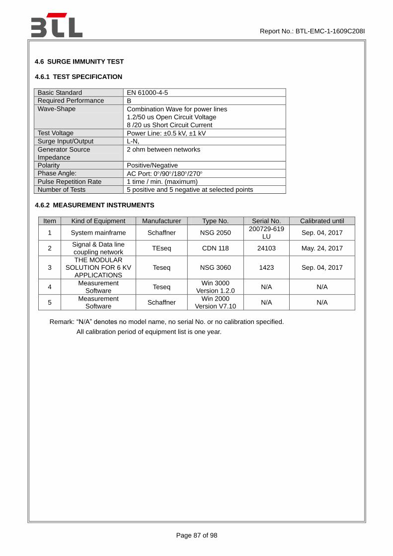
4.6 SURGE IMMUNITY TEST
4.6.1 TEST SPECIFICATION
Basic Standard EN 61000-4-5
Required Performance B
Wave-Shape Combination Wave for power lines
1.2/50 us Open Circuit Voltage
8 /20 us Short Circuit Current
Test Voltage Power Line: ±0.5 kV, ±1 kV
Surge Input/Output L-N,
Generator Source
Impedance
2 ohm between networks
Polarity Positive/Negative
Phase Angle: AC Port: 0/90/180/270
Pulse Repetition Rate 1 time / min. (maximum)
Number of Tests 5 positive and 5 negative at selected points
4.6.2 MEASUREMENT INSTRUMENTS
Item Kind of Equipment Manufacturer Type No. Serial No. Calibrated until
1 System mainframe Schaffner NSG 2050 200729-619
LU Sep. 04, 2017
2 Signal & Data line coupling network
TEseq CDN 118 24103 May. 24, 2017
3 THE MODULAR
SOLUTION FOR 6 KV APPLICATIONS
Teseq NSG 3060 1423 Sep. 04, 2017
4 Measurement
Software Teseq
Win 3000 Version 1.2.0
N/A N/A
5 Measurement
Software Schaffner
Win 2000 Version V7.10
N/A N/A
Remark: “N/A” denotes no model name, no serial No. or no calibration specified.
All calibration period of equipment list is one year.

Report No.: BTL-EMC-1-1609C208I
Page 88 of 98
4.6.3 TEST PROCEDURE
a. For EUT power supply:
The surge is to be applied to the EUT power supply terminals via the capacitive coupling network. Decoupling networks are required in order to avoid possible adverse effects on equipment not under test that may be powered by the same lines, and to provide sufficient decoupling impedance to the surge wave. The power cord between the EUT and the coupling/decoupling networks shall be 2meters in length (or shorter).
b. For test applied to unshielded unsymmetrically operated interconnection lines of EUT :
The surge is applied to the lines via the capacitive coupling. The coupling /decoupling networks shall not influence the specified functional conditions of the EUT. The interconnection line between the EUT and the coupling/decoupling networks shall be 2 meters in length (or shorter).
c. For test applied to unshielded symmetrically operated interconnection /telecommunication lines of EUT :
The surge is applied to the lines via gas arrestors coupling. Test levels below the ignition point of the coupling arrestor cannot be specified. The interconnection line between the EUT and the coupling/decoupling networks shall be 2 meters in length (or shorter).
4.6.4 DEVIATION FROM TEST STANDARD
No deviation
4.6.5 TEST SETUP
EUT
To AC Mains or
DC Power
Supply
Non-Metallic Table
Coupling
Network
Combination Wave
Generator
Decoupling
Network
AC/DC Power Supply
and Surge Voltage
Coupling to EUT

Report No.: BTL-EMC-1-1609C208I
Page 89 of 98
4.6.6 TEST RESULTS
EUT IP Phone Model Name XT-19P
Temperature 25°C Relative Humidity 48%
Test Voltage AC 230V/50Hz
Test Mode Handfree,Handset,Earphone
Wave Form EUT Ports Tested
1.2/50(8/20)Tr/Thμs
Criterion Result Judgment Polarity Phase
Voltage
0.5kV 1kV -- kV -- kV
AC L – N
(2 ohm)
+/- 0 A A - -
B A PASS +/- 90 A A - -
+/- 180 A A - -
+/- 270 A A - -
Note:
1) Polarity and Numbers of Impulses: 5 Pst / Ngt at each tested mode
2) N/A - denotes test is not applicable in this Test Report
3) Criterion A: No observation of any performance degradation.
4) Criterion B: Some degradation of performance is observed but the equipment continues to operate as intended.
5) Criterion C: Loss of functionality, but self-recoverable by user, without loss of information or settings.

Report No.: BTL-EMC-1-1609C208I
Page 90 of 98
4.7 IMMUNITY TO CONDUCTED DISTURBANCES, INDUCED BY RADIO-FREQUENCY FIELDS TEST (CS)
4.7.1 TEST SPECIFICATION
Basic Standard EN 61000-4-6
Required Performance A
Frequency Range 0.15 MHz - 80 MHz
Field Strength 3 V (unmodulated, r.m.s.)
Modulation 1 kHz Sine Wave, 80%, AM Modulation
Frequency Step 1% of fundamental
Dwell Time at least 3 seconds
4.7.2 MEASUREMENT INSTRUMENTS
Item Kind of Equipment Manufacturer Type No. Serial No. Calibrated until
1 Measurement
Software TOYO IM5/C Ver 3.7.028 N/A N/A
2 Power CDN FCC FCC-801-M2/M3-
16A 100270 Mar. 27, 2017
3 Power Amplifier Teseq CBA230M-080 T43748 Mar. 27, 2017
4 Signal Generator HP 8648A 3636A02964 Mar. 27, 2017
5 Measurement
Software Farad EZ-CS(V2.0.1.2) N/A N/A
6 Signal Line CDN FCC
F-090407- 1004-1
100518 Mar. 27, 2017
Remark: “N/A” denotes no model name, no serial No. or no calibration specified.
All calibration period of equipment list is one year.
4.7.3 TEST PROCEDURE
The EUT and support equipment, are placed on a table that is 0.8 meter above a metal ground plane measured 1m*1m min. and 0.65mm thick min. The other condition as following manner:
a. The field strength level was 3 V (unmodulated, r.m.s.)
b. The frequency range is swept from 150 kHz to 80 MHz, with the signal 80%amplitude modulated with a 1 kHz sine wave. The rate of sweep did not exceed 1.5x 10⁻³ decade/s. Where the frequency range is swept incrementally, the step size was 1% of fundamental.
c. The dwell time at each frequency shall be not less than the time necessary for the EUT to be able to respond.
4.7.4 DEVIATION FROM TEST STANDARD
No deviation
Report No.: BTL-EMC-1-1609C208I
Page 91 of 98
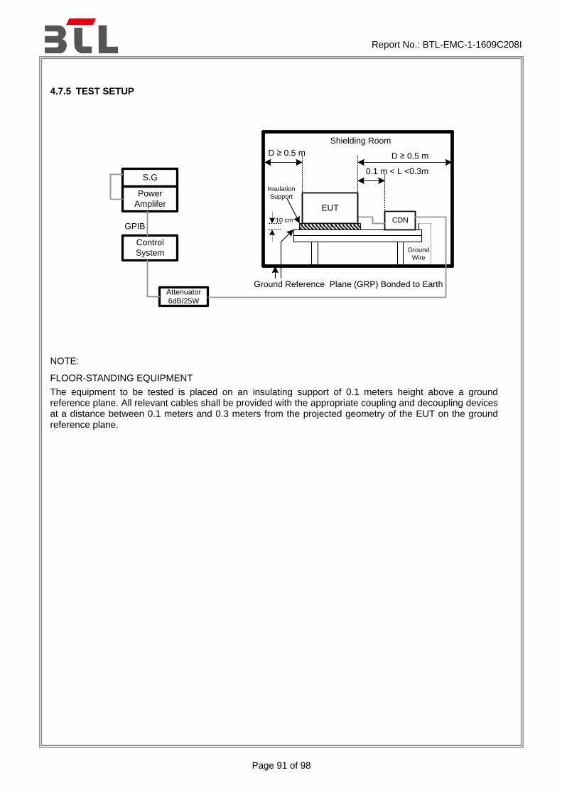
4.7.5 TEST SETUP
Attenuator
6dB/25W
S.G
GPIB
D ≥ 0.5 m
Power
Amplifer
Control
System
Shielding Room
EUT
CDN
D ≥ 0.5 m
0.1 m < L <0.3m
Ground Reference Plane (GRP) Bonded to Earth
10 cm
Insulation
Support
Ground
Wire
NOTE:
FLOOR-STANDING EQUIPMENT
The equipment to be tested is placed on an insulating support of 0.1 meters height above a ground reference plane. All relevant cables shall be provided with the appropriate coupling and decoupling devices at a distance between 0.1 meters and 0.3 meters from the projected geometry of the EUT on the ground reference plane.

Report No.: BTL-EMC-1-1609C208I
Page 92 of 98
4.7.6 TEST RESULTS
EUT IP Phone Model Name XT-19P
Temperature 25°C Relative Humidity 52%
Test Voltage AC 230V/50Hz
Test Mode Handfree,Handset,Earphone
Test Ports (Mode)
Freq.Range (MHz)
Field Strength Criteria Results Judgment
Input/ Output AC.PowerPort
0.15 ---80
3V(unmodulated, r.m.s)
AM Modulated 1000Hz, 80%
A A PASS
Input/ Output DC. PowerPort
0.15 --- 80 A N/A N/A
Signal Line (RJ45)
0.15 --- 80 A A PASS
Note:
1). N/A - denotes test is not applicable in this test report.
2) Criterion A: No observation of any performance degradation.
3) Criterion B: Some degradation of performance is observed but the equipment continues to operate as intended.
4) Criterion C: Loss of functionality, but self-recoverable by user, without loss of information or settings.

Report No.: BTL-EMC-1-1609C208I
Page 93 of 98
4.8 POWER FREQUENCY MAGNETIC FIELD IMMUNITY TEST (PFMF)
4.8.1 TEST SPECIFICATION
Basic Standard EN 61000-4-8
Required Performance A
Frequency Range 50/60 Hz
Field Strength 1 A/m
Observation Time 1 minute
Inductance Coil Rectangular type, 1mx1m
4.8.2 MEASUREMENT INSTRUMENTS
Item Kind of Equipment Manufacturer Type No. Serial No. Calibrated until
1 Magnetic Field test
Generator FCC
F-1000-4-8-G-125A
04032 Mar. 27, 2017
2 Magnetic Field immunity loop
Thermo KeyTek F-1000-4-8/9
/10-L-1M 04024 Mar. 27, 2017
Remark: “N/A” denotes no model name, no serial No. or no calibration specified.
All calibration period of equipment list is one year.
4.8.3 TEST PROCEDURE
The EUT and support equipment, are placed on a table that is 0.8 meter above a metal ground plane measured 1m*1m min. and 0.65mm thick min. The other condition as following manner:
a. The equipment cabinets shall be connected to the safety earth directly on the GRP via the earth terminal of the EUT.
b. The cables supplied or recommended by the equipment manufacturer shall be used. 1 meter of all cables used shall be exposed to the magnetic field.
4.8.4 DEVIATION FROM TEST STANDARD
No deviation

Report No.: BTL-EMC-1-1609C208I
Page 94 of 98
4.8.5 TEST SETUP
Magnetic
Field
Tester
EUT
AC
Source
Note:
TABLE-TOP EQUIPMENT
The equipment shall be subjected to the test magnetic field by using the induction coil of standard dimension (1 m x 1 m). The induction coil shall then be rotated by 90 degrees in order to expose the EUT to the test field with different orientations.
FLOOR-STANDING EQUIPMENT
The equipment shall be subjected to the test magnetic field by using induction coils of suitable dimensions. The test shall be repeated by moving and shifting the induction coils, in order to test the whole volume of the EUT for each orthogonal direction. The test shall be repeated with the coil shifted to different positions along the side of the EUT, in steps corresponding to 50 percent of the shortest side of the coil. The induction coil shall then be rotated by 90 degrees in order to expose the EUT to the test field with different orientations.

Report No.: BTL-EMC-1-1609C208I
Page 95 of 98
4.8.6 TEST RESULTS
EUT IP Phone Model Name XT-19P
Temperature 25°C Relative Humidity 48%
Test Voltage AC 230V/50Hz
Test Mode Handfree,Handset,Earphone
50Hz
Test Mode Test Level Antenna aspect
Duration (s)
Criteria Results Judgment
Enclosure 1 A/m X 60 A A PASS
Enclosure 1 A/m Y 60 A A PASS
Enclosure 1 A/m Z 60 A A PASS
60Hz
Test Mode Test Level Antenna aspect
Duration (s)
Criteria Results Judgment
Enclosure 1 A/m X 60 A A PASS
Enclosure 1 A/m Y 60 A A PASS
Enclosure 1 A/m Z 60 A A PASS
Note:
1). N/A - denotes test is not applicable in this test report.
2) Criterion A: No observation of any performance degradation.
3) Criterion B: Some degradation of performance is observed but the equipment continues to operate as intended.
4) Criterion C: Loss of functionality, but self-recoverable by user, without loss of information or settings.

Report No.: BTL-EMC-1-1609C208I
Page 96 of 98
4.9 VOLTAGE DIPS, SHORT INTERRUPTIONS AND VOLTAGE VARIATIONS IMMUNITY TEST
4.9.1 TEST SPECIFICATION
Basic Standard EN 61000-4-11
Required Performance B (For >95% Voltage Dips) C (For 30% Voltage Dips) C (For >95% Voltage Interruptions)
Test Duration Time Minimum three test events in sequence
Interval between Event Minimum ten seconds
Phase Angle 0°/180°
Test Cycle 3 times
4.9.2 MEASUREMENT INSTRUMENTS
Item Kind of Equipment Manufacturer Type No. Serial No. Calibrated until
1 THE MODULAR
SOLUTION FOR 6 KV APPLICATIONS
Teseq NSG 3060 1423 Sep. 04, 2017
2 Measurement Software
Teseq Win 3000
Version 1.2.0 N/A N/A
Remark: “N/A” denotes no model name, no serial No. or no calibration specified.
All calibration period of equipment list is one year.
4.9.3 TEST PROCEDURE
The EUT shall be tested for each selected combination of test levels and duration with a sequence of three dips/interruptions with intervals of 10 s minimum (between each test event). Each representative mode of operation shall be tested. Abrupt changes in supply voltage shall occur at zero crossings of the voltage waveform.
4.9.4 DEVIATION FROM TEST STANDARD
No deviation

Report No.: BTL-EMC-1-1609C208I
Page 97 of 98
4.9.5 TEST SETUP
EUT
To AC Mains
Power Supply
Non-Metallic Table
Voltage Dips
Generator
Voltage Supply
To EUT

Report No.: BTL-EMC-1-1609C208I
Page 98 of 98
4.9.6 TEST RESULTS
EUT IP Phone Model Name XT-19P
Temperature 25°C Relative Humidity 48%
Test Voltage AC 230V/50Hz
Test Mode Handfree,Handset,Earphone
AC 100V/50Hz
VoltageReduction Periods Criteria Results Judgment
Voltage dip >95% 0.5 B A PASS
Voltage dip 30% 25 C A PASS
Interruption>95% 250 C C PASS
AC 230V/50Hz
VoltageReduction Periods Criteria Results Judgment
Voltage dip >95% 0.5 B A PASS
Voltage dip 30% 25 C A PASS
Interruption>95% 250 C C PASS
AC 240V/50Hz
VoltageReduction Periods Criteria Results Judgment
Voltage dip >95% 0.5 B A PASS
Voltage dip 30% 25 C A PASS
Interruption>95% 250 C C PASS
Note:
1). N/A - denotes test is not applicable in this test report. 2) Criterion A: No observation of any performance degradation. 3) Criterion B: Some degradation of performance is observed but the equipment continues to
operate as intended. 4) Criterion C: Loss of functionality, but self-recoverable by user, without loss of information or
settings.
End of Test Report