Embed Size (px)
Citation preview

CERPASS TECHNOLOGY CORP. Report No.: SECE1605055
Cerpass Technology (Suzhou) Co., Ltd Issued Date : May 12, 2016
Report format Revision 01 Page No. : 1 of 135
EMC TEST REPORT
Authorized under Declaration of Conformity
According to
EN 55022 : 2010/AC:2011 (Class B) EN 55024 : 2010
EN 61000-6-3: 2007/A1:2011 EN 50130-4: 2011
EN 61000-3-2 : 2014 IEC 61000-4-2 : 2008
EN 61000-3-3 : 2013 IEC 61000-4-3 : 2006+A1:2007+A2:2010
IEC 61000-4-4 : 2012
IEC 61000-4-5 : 2005
IEC 61000-4-6 : 2008
IEC 61000-4-8 : 2009
IEC 61000-4-11 : 2004
Applicant : Panasonic India Pvt. Ltd.
Address : 6th Floor, "SPIC BUILDING" Annexe, No. 88, Mount Road, Guindy, Chennai - 600 032.
Equipment : Network Dome Camera
Model No. : PI-SFW201L,PI-SFW401L
Trade Name : Panasonic
I HEREBY CERTIFY THAT :
The sample was received on Jun 02, 2015 and the testing was carried out on Jun 24, 2015 at Cerpass Technology Corp. The test result refers exclusively to the test presented test model / sample. Without written approval of Cerpass Technology Corp., the test report shall not be reproduced except in full.

CERPASS TECHNOLOGY CORP. Report No.: SECE1605055
Cerpass Technology (Suzhou) Co., Ltd Issued Date : May 12, 2016
Report format Revision 01 Page No. : 2 of 135
EMC TEST REPORT Issued by:
Cerpass Technology (Suzhou) Co.,Ltd
No.66,Tangzhuang Road, Suzhou Industrial Park, Jiangsu 215006, China
Tel:86-512-6917-5888
Fax:86-512-6917-5666
The test record, data evaluation & Equipment Under Test configurations represented herein are true and accurate accounts of the measurements of the samples EMC characteristics under the conditions specified in this report.
The above equipment was tested by Cerpass Technology Corp. for compliance with the requirements of technical standards specified above under the EMC Directive 2004/108/EC & 2014/30/EU. The results of testing in this report apply only to the product/system, which was tested. Other similar equipment will not necessarily produce the same results due to production tolerance and measurement uncertainties
Approved by:
Miro Chueh
EMC/RF B.U. Manager
Laboratory Accreditation:
Cerpass Technology Corporation Test Laboratory
NVLAP LAB Code: 200954-0
TAF LAB Code: 1439
Cerpass Technology(SuZhou) Co., Ltd.
NVLAP LAB Code: 200814-0
CNAS LAB Code: L5515

CERPASS TECHNOLOGY CORP. Report No.: SECE1605055
Cerpass Technology (Suzhou) Co., Ltd Issued Date : May 12, 2016
Report format Revision 01 Page No. : 3 of 135
Contents
1. Summary of Test Procedure and Test Results ......................................................................................... 6
2. Immunity Testing Performance Criteria Definition .................................................................................. 7
3. Test Configuration of Equipment under Test ........................................................................................... 8
3.1. Manufacturer .................................................................................................................................... 8
3.2. Feature of Equipment under Test ..................................................................................................... 8
3.3. Test Manner ..................................................................................................................................... 9
3.4. Description of Support Unit ............................................................................................................ 10
3.5. General Information of Test ............................................................................................................ 11
3.6. Measurement Uncertainty .............................................................................................................. 12
4. Test of Conducted Emission .................................................................................................................... 14
4.1. Test Limit ........................................................................................................................................ 14
4.2. Test Procedures ............................................................................................................................. 15
4.3. Typical Test Setup .......................................................................................................................... 15
4.4. Measurement Equipment ............................................................................................................... 16
4.5. Test Result and Data ...................................................................................................................... 17
4.6. Test Photographs of Power Port .................................................................................................... 33
4.7. Test Photographs of Telecommunication Port ................................................................................ 34
5. Test of Radiated Emission ....................................................................................................................... 35
5.1. Test Limit ........................................................................................................................................ 35
5.2. Test Procedures ............................................................................................................................. 36
5.3. Typical Test Setup .......................................................................................................................... 36
5.4. Measurement Equipment ............................................................................................................... 37
5.5. Test Result and Data (30MHz ~ 1GHz).......................................................................................... 38
5.6. Test Result and Data (1GHz ~ 6GHz) ............................................................................................ 50
5.7. Test Photographs (30MHz~1GHz) ................................................................................................. 62
5.8. Test Photographs (1GHz~6GHz) ................................................................................................... 63
6. Harmonics Test.......................................................................................................................................... 64
6.1. Limits of Harmonics Current Measurement ................................................................................... 64
6.2. Measurement equipment ............................................................................................................... 65
6.3. Test Result and Data ...................................................................................................................... 66
6.4. Test Photographs ........................................................................................................................... 74
7. Voltage Fluctuations Test ......................................................................................................................... 75
7.1. Test Procedure ............................................................................................................................... 75
7.2. Measurement Equipment ............................................................................................................... 75
7.3. Test Result and Data ...................................................................................................................... 76
7.4. Test Photographs ........................................................................................................................... 84
8. Electrostatic Discharge Immunity Test ................................................................................................... 85
8.1. Test Procedure ............................................................................................................................... 85
8.2. Test Setup for Tests Performed in Laboratory ................................................................................ 86
8.3. Test Severity Levels ....................................................................................................................... 87
8.4. Measurement Equipment ............................................................................................................... 87
8.5. Test Result and Data ...................................................................................................................... 88
8.6. Test Photographs ........................................................................................................................... 91

CERPASS TECHNOLOGY CORP. Report No.: SECE1605055
Cerpass Technology (Suzhou) Co., Ltd Issued Date : May 12, 2016
Report format Revision 01 Page No. : 4 of 135
9. Radio Frequency electromagnetic field immunity test ......................................................................... 98
9.1. Test Procedure ............................................................................................................................... 98
9.2. Test Severity Levels ....................................................................................................................... 98
9.3. TEST SETUP ................................................................................................................................. 99
9.4. Measurement Equipment ............................................................................................................. 100
9.5. Test Result and Data .................................................................................................................... 101
9.6. Test Photographs ......................................................................................................................... 103
10. Electrical Fast Transient/ Burst Immunity Test .................................................................................... 104
10.1. Test Procedure ............................................................................................................................. 104
10.2. Test Severity Levels ..................................................................................................................... 104
10.3. TEST SETUP ............................................................................................................................... 105
10.4. Measurement Equipment ............................................................................................................. 106
10.5. Test Result and Data .................................................................................................................... 107
10.6. Test Photographs ......................................................................................................................... 109
11. Surge Immunity Test ............................................................................................................................... 111
11.1. Test Procedure ............................................................................................................................. 111
11.2. Test Severity Level ....................................................................................................................... 111
11.3. TEST SETUP ............................................................................................................................... 112
11.4. Measurement Equipment ............................................................................................................. 112
11.5. Test Result and Data .................................................................................................................... 113
11.6. Test Photographs ......................................................................................................................... 117
12. Conduction Disturbances induced by Radio-Frequency Fields ........................................................ 118
12.1. Test Procedure ............................................................................................................................. 118
12.2. Test Severity Levels ..................................................................................................................... 118
12.3. TEST SETUP ............................................................................................................................... 119
12.4. Measurement Equipment ............................................................................................................. 119
12.5. Test Result and Data .................................................................................................................... 120
12.6. Test Photographs ......................................................................................................................... 122
13. Power Frequency Magnetic Field Immunity Test ................................................................................. 123
13.1. Test Setup .................................................................................................................................... 123
13.2. Test Severity Levels ..................................................................................................................... 123
13.3. Measurement Equipment ............................................................................................................. 123
13.4. Test Result and Data .................................................................................................................... 124
13.5. Test Photographs ......................................................................................................................... 125
14. Voltage Dips and Voltage Interruptions Immunity Test Setup ............................................................ 126
14.1. Test Conditions ............................................................................................................................. 126
14.2. TEST SETUP ............................................................................................................................... 126
14.3. Measurement Equipment ............................................................................................................. 126
14.4. Test Result and Data .................................................................................................................... 127
15. EUT Photographs .................................................................................................................................... 128

CERPASS TECHNOLOGY CORP. Report No.: SECE1605055
Cerpass Technology (Suzhou) Co., Ltd Issued Date : May 12, 2016
Report format Revision 01 Page No. : 5 of 135
History of this test report
� ORIGINAL.
� Additional attachment as following record:
Report No Version Date Description
SECE1605055 Rev 01 May 12, 2016 Initial Issue

CERPASS TECHNOLOGY CORP. Report No.: SECE1605055
Cerpass Technology (Suzhou) Co., Ltd Issued Date : May 12, 2016
Report format Revision 01 Page No. : 6 of 135
1. Summary of Test Procedure and Test Results
EMISSION[EN 55022: 2010/AC:2011]
Standard Item Result Remarks
EN55022: 2010/AC:2011
Conducted (Power Port) PASS
Meet Class B Limit Minimum passing
margin(AV) is -2.31 dB at 0.3260 MHz
Conducted (Telecom port) PASS
Meets Class B Limit Minimum passing
margin(AV) is -2.00 dB 0.3339 MHz
Radiated PASS
Meets Class B Limit Minimum passing
margin(QP) is -3.92 dB at 575.1399 MHz
EN 61000-3-2: 2014 Harmonic current emissions PASS Meet Class A Limit
EN61000-3-3:2013 Voltage fluctuations & flicker PASS Meets the requirements
IMMUNITY[EN 55024:2010]
Standard Item Result Remarks
IEC 61000-4-2: 2008 ESD PASS Meets the requirements of Performance Criterion A
IEC 61000-4-3: 2006+A1:2007+A2:2010
RS PASS Meets the requirements of Performance Criterion A
IEC 61000-4-4: 2012 EFT PASS Meets the requirements of Performance Criterion A
IEC 61000-4-5:2005 Surge PASS Meets the requirements of Performance Criterion A
IEC 61000-4-6:2008 CS PASS Meets the requirements of Performance Criterion A
IEC 61000-4-8:2009 PFMF PASS Meets the requirements of Performance Criterion A
IEC 61000-4-11:2004 Voltage dips
& voltage variations
N/A N/A

CERPASS TECHNOLOGY CORP. Report No.: SECE1605055
Cerpass Technology (Suzhou) Co., Ltd Issued Date : May 12, 2016
Report format Revision 01 Page No. : 7 of 135
IMMUNITY[EN 50130-4: 2011]
Standard Item Result Remarks
IEC 61000-4-2: 2008 ESD PASS Meets the requirements of Performance Criterion A
IEC 61000-4-3: 2006+A1:2007+A2:2010
RS PASS Meets the requirements of Performance Criterion A
IEC 61000-4-4: 2012 EFT PASS Meets the requirements of Performance Criterion A
IEC 61000-4-5:2005 Surge PASS Meets the requirements of Performance Criterion A
IEC 61000-4-6:2008 CS PASS Meets the requirements of Performance Criterion A
IEC 61000-4-11:2004 Voltage dips
& voltage variations
N/A N/A
2. Immunity Testing Performance Criteria Definition
A. Normal performance within limits specified by the manufacture, requestor or purchaser;
B. Temporary loss of function or degradation of performance which ceases after the disturbance
ceases, and from which the equipment under test recovers its normal performance, without
operator intervention;
C. Temporary loss of function or degradation of performance, the correction of which requires
operation intervention;
D. Loss of function or degradation of performance which is not recoverable, owing to damage to
hardware or software, or loss of data.

CERPASS TECHNOLOGY CORP. Report No.: SECE1605055
Cerpass Technology (Suzhou) Co., Ltd Issued Date : May 12, 2016
Report format Revision 01 Page No. : 8 of 135
3. Test Configuration of Equipment under Test
3.1. Manufacturer
Panasonic India Pvt. Ltd.
6th Floor, "SPIC BUILDING" Annexe, No. 88, Mount Road, Guindy, Chennai - 600 032.
3.2. Feature of Equipment under Test
Network
Dome
Camera
Model No.: PI-SFW201L,PI-SFW401L
Input: 12V, 1A/24V~0.8A,50-60Hz POE:48V~0.26A
Remark
1.PI-SFW201L, PI-SFW401L are Only different SENSOR board.
2.PI-SFW401L, PI-SFW201L were selected as the test model and its da
ta have been recorded in this report. They are identical except the sale
area or software.
Adapter 1#
Model No.: ADS-12B-12 12012Gz
INPUT: 100-240V~ 50/60Hz Max. 0.3A
OUTPUT: 12V, 1.0A
Adapter 2#
Model No.: HKA-A24150-230
INPUT: 230V~50Hz
OUTPUT: 24V~1500mA 36VA
I/O PORT:
I/O PORT TYPE Quantity
1). RJ45 Port 1

CERPASS TECHNOLOGY CORP. Report No.: SECE1605055
Cerpass Technology (Suzhou) Co., Ltd Issued Date : May 12, 2016
Report format Revision 01 Page No. : 9 of 135
3.3. Test Manner
Test Manner
a During testing, the interface cables and equipment positions were varied according
to Europe Standard.
b Turn on the power of all equipment.
c The complete test system included Notebook PC, DVR and EUT for EMI test.
The pre-test modes for RE
Mode 1: Full system for PI-SFW401L with Adapter #1 + POE
Mode 2: Full system for PI-SFW401L with Adapter #2 + POE
Mode 3: Full system for PI-SFW401L with POE
Mode 4: Full system for PI-SFW201L with Adapter #1 + POE
Mode 5: Full system for PI-SFW201L with Adapter #2 + POE
Mode 6: Full system for PI-SFW201L with POE
The pre-test modes for CE/EMC/H&F
Mode 1: Full system for PI-SFW401L with Adapter #1 + POE
Mode 2: Full system for PI-SFW401L with Adapter #2 + POE
Mode 3: Full system for PI-SFW201L with Adapter #1 + POE
Mode 4: Full system for PI-SFW201L with Adapter #2 + POE
The pre-test modes for ISN
Mode 1: Full system for PI-SFW401L with Adapter #1 (LAN 10Mbps+POE)
Mode 2: Full system for PI-SFW401L with Adapter #1 (LAN 100Mbps+POE)
Mode 3: Full system for PI-SFW401L with Adapter #2 (LAN 10Mbps+POE)
Mode 4: Full system for PI-SFW401L with Adapter #2 (LAN 100Mbps+POE)
Mode 5: Full system for PI-SFW201L with Adapter #1 (LAN 10Mbps+POE)
Mode 6: Full system for PI-SFW201L with Adapter #1 (LAN 100Mbps+POE)
Mode 7: Full system for PI-SFW201L with Adapter #2 (LAN 10Mbps+POE)
Mode 8: Full system for PI-SFW201L with Adapter #2 (LAN 100Mbps+POE)
Select the worst case of the pre-test modes as the final test mode
For RE
Mode 1: Full system for PI-SFW401L with Adapter #1 + POE
Mode 2: Full system for PI-SFW401L with Adapter #2 + POE
Mode 3: Full system for PI-SFW401L with POE
Mode 4: Full system for PI-SFW201L with Adapter #1 + POE
Mode 5: Full system for PI-SFW201L with Adapter #2 + POE
Mode 6: Full system for PI-SFW201L with POE
For CE/EMC/H&F
Mode 1: Full system for PI-SFW401L with Adapter #1 + POE

CERPASS TECHNOLOGY CORP. Report No.: SECE1605055
Cerpass Technology (Suzhou) Co., Ltd Issued Date : May 12, 2016
Report format Revision 01 Page No. : 10 of 135
Mode 2: Full system for PI-SFW401L with Adapter #2 + POE
Mode 3: Full system for PI-SFW201L with Adapter #1 + POE
Mode 4: Full system for PI-SFW201L with Adapter #2 + POE
For ISN
Mode 1: Full system for PI-SFW401L with Adapter #1 (LAN 10Mbps+POE)
Mode 2: Full system for PI-SFW401L with Adapter #1 (LAN 100Mbps+POE)
Mode 3: Full system for PI-SFW401L with Adapter #2 (LAN 10Mbps+POE)
Mode 4: Full system for PI-SFW401L with Adapter #2 (LAN 100Mbps+POE)
Mode 5: Full system for PI-SFW201L with Adapter #1 (LAN 10Mbps+POE)
Mode 6: Full system for PI-SFW201L with Adapter #1 (LAN 100Mbps+POE)
Mode 7: Full system for PI-SFW201L with Adapter #2 (LAN 10Mbps+POE)
Mode 7: Full system for PI-SFW201L with Adapter #2 (LAN 100Mbps+POE)
3.4. Description of Support Unit
No. Device Manufacturer Model No. Description
1 Notebook PC SONY PCG-71811P Non-Shielded,1.5m
(R33021)
2 DVR Dahua N/A Non-Shielded,1.5m
No. Cable Quantity Description
A LAN Cable 1 Non-Shielded>3.0 m
B LAN Cable 1 Non-Shielded>3.0 m
C DC Cable 1 Non-Shielded,1.5m
CERPASS TECHNOLOGY CORP. Report No.: SECE1605055
Cerpass Technology (Suzhou) Co., Ltd Issued Date : May 12, 2016
Report format Revision 01 Page No. : 11 of 135
3.5. General Information of Test
Test Site
Cerpass Technology Corporation Test Laboratory
Address: No.10, Ln. 2, Lianfu St., Luzhu Dist., Taoyuan City
33848, Taiwan (R.O.C.)
Tel:+886-3-3226-888
Fax:+886-3-3226-881
Address: No.68-1, Shihbachongsi, Shihding Township,
New Taipei City 223, Taiwan, R.O.C.
Tel: +886-2-2663-8582
FCC TW1079, TW1061,390316, 228391, 641184
IC 4934B-1, 4934E-1, 4934E-2
VCCI
T-2205 for Telecommunication Test
C-4463 for Conducted emission test
R-3428, R-4128 for Radiated emission test
G-812, G-813 for radiated disturbance above 1GHz
Test Site
Cerpass Technology (Suzhou) Co.,Ltd
Address: No.66,Tangzhuang Road, Suzhou Industrial Park,
Jiangsu 215006, China
Tel: +86-512-6917-5888
Fax: +86-512-6917-5666
FCC 331395
IC 7290A-1, 7290A-2
VCCI
T-1945 for Telecommunication Test
C-2919 for Conducted emission test
R-2670 for Radiated emission test
G-227 for radiated disturbance above 1GHz
Frequency Range Investigated: Conducted: from 150kHz to 30 MHz
Radiation: from 30 MHz to 6000MHz
Test Distance :
The test distance of radiated emission below 1GHz from
antenna to EUT is 10 M.
The test distance of radiated emission above 1GHz from
antenna to EUT is 3 M.

CERPASS TECHNOLOGY CORP. Report No.: SECE1605055
Cerpass Technology (Suzhou) Co., Ltd Issued Date : May 12, 2016
Report format Revision 01 Page No. : 12 of 135
3.6. Measurement Uncertainty
Where relevant, the following measurement uncertainty levels have been estimated for tests performed
on the EUT as specified in CISPR 16-4-2:
Measurement Frequency Uncertainty
Conducted emissions(LINE) 9KHz-30MHz +/- 0.6888 dB
Conducted emissions(NEUTRAL) 9KHz-30MHz +/- 0.7002 dB
Measurement Polarity Frequency Uncertainty
Radiated emissions
(below 1GHz)
H 30MHz ~ 200MHz +/- 4.0677dB
200MHz ~1000MHz +/- 3.9131dB
V 30MHz ~ 200MHz +/- 4.0678dB
200MHz ~1000MHz +/- 3.9142dB
Radiated emissions
(above 1GHz)
H 1000MHz ~18000MHz +/- 3.8904 dB
18000MHz ~40000MHz +/-3.9356dB
V 1000MHz ~18000MHz +/- 3.8896dB
18000MHz ~40000MHz +/- 3.8766dB
Measurement Uncertainty
ESD—Rise time tr 6.4%
ESD—Peak current Ip 6%
ESD—Current at 30 ns 6%
ESD—Current at 60 ns 6%
ESD- Charging voltage 1%
RS above 1GHz ±2.28dB
RS under 1GHz ±3.62dB
EFT—Rise time tr 4%
EFT—Peak current Ip 4%
EFT—Current 4%
Surge—Rise time tr 4%
Surge—Peak current Ip 4%

CERPASS TECHNOLOGY CORP. Report No.: SECE1605055
Cerpass Technology (Suzhou) Co., Ltd Issued Date : May 12, 2016
Report format Revision 01 Page No. : 13 of 135
Surge—Current 4%
CS-CND ±0.80dB
CS-Clamp ±1.06dB
This uncertainty represents an expanded uncertainty expressed at approximately the 95% confidence level using a coverage factor of k=2.
Consistent with industry standard (e.g. CISPR 22: 2008, clause 11, Measurement Uncertainty) determining compliance with the limits shall be base on the results of the compliance measurement. Consequently the measure emissions being less than the maximum allowed emission result in this be a compliant test or passing test.

CERPASS TECHNOLOGY CORP. Report No.: SECE1605055
Cerpass Technology (Suzhou) Co., Ltd Issued Date : May 12, 2016
Report format Revision 01 Page No. : 14 of 135
4. Test of Conducted Emission
4.1. Test Limit
Conducted Emissions were measured from 150 kHz to 30 MHz with a bandwidth of 9 kHz and
return leads of the EUT according to the methods defined in European Standard EN 55022. The
EUT was placed on a nonmetallic stand in a shielded room 0.8 meters above the ground plane as
shown in section 4.2. The interface cables and equipment positioning were varied within limits
of reasonable applications to determine the position producing maximum conducted emissions.
Table 1 Conducted Emission Limits (dBµV):
Table 2 - Limits of conducted common mode (asymmetric mode) disturbance at telecommunication ports in the frequency range 0.15 MHz to 30 MHz(dB(μV)).
Frequency
range
(MHz)
Class A Equipment Class B Equipment
Voltage Current Voltage Current
Quasi Peak
Avg. Quasi Peak
Avg. Quasi Peak
Avg. Quasi Peak
Avg.
0.15 to 0.5 97~ 87 84~74 53~43 40~30 84~74 74~64 40~30 30~20
0.5 to 5 87 74 43 30 74 64 30 20
5 to 30 87 74 43 30 74 64 30 20
Note 1: The limits decrease linearly with the logarithm of the frequency in the range 0.15 to 0.5 MHz.
Note 2 : The current and voltage disturbance limits are derived for use with an impedance stabilization
network (ISN) which presents a common mode (asymmetric mode) impedance of 150Ω to the
telecommunication under test (conversion factor is 20 log10 150/1 = 44dB).
Frequency range
(MHz)
Class A Equipment Class B Equipment
Quasi Peak Average Quasi Peak Average
0.15 to 0.50 79 66 66 to 56 56 to 46
0.50 to 5 73 60 56 46
5. to 30. 73 60 60 50
Note 1: The lower limits shall apply at the transition frequencies.
Note 2:The limit decreases linearly with the logarithm of the frequency in the range 0.15
MHz to 0.5MHz.

CERPASS TECHNOLOGY CORP. Report No.: SECE1605055
Cerpass Technology (Suzhou) Co., Ltd Issued Date : May 12, 2016
Report format Revision 01 Page No. : 15 of 135
4.2. Test Procedures
a. The EUT was placed on a desk 0.8 meters height from the metal ground plane and 0.4 meter
from the conducting wall of the shielding room and it was kept at least 0.8 meters from any
other grounded conducting surface.
b. Connect EUT to the power mains through a line impedance stabilization network (LISN).
c. All the support units are connecting to the other LISN.
d. The LISN provides 50 ohm coupling impedance for the measuring instrument.
e. The CISPR states that a 50 ohm, 50 micro-Henry LISN should be used.
f. Both sides of AC line were checked for maximum conducted interference.
g. The frequency range from 150 kHz to 30 MHz was searched
h. Set the test-receiver system to Peak Detect Function and Specified Bandwidth with Maximum
Hold Mode.
4.3. Typical Test Setup
10cm
80cm
EUT
80cm
40cm
LISN
80cm
Note:L
LISN ISN
AE

CERPASS TECHNOLOGY CORP. Report No.: SECE1605055
Cerpass Technology (Suzhou) Co., Ltd Issued Date : May 12, 2016
Report format Revision 01 Page No. : 16 of 135
4.4. Measurement Equipment
Instrument/Ancillary Manufacturer Model No. Serial No. Calibration
Date Valid Date.
Test Receiver R&S ESCI 100565 2015.03.29 2016.03.28
AMN R&S ESH2-Z5 100182 2014.09.04 2015.09.03
Two-Line V-Network R&S ENV216 100325 / /
ISN FCC FCC-TLISN-T2-02 20379 2015.03.29 2016.03.28
ISN FCC FCC-TLISN-T4-02 20380 2015.03.29 2016.03.28
ISN FCC FCC-TLISN-T8-02 20381 2015.03.29 2016.03.28
ISN TESEQ ISN ST08 30175 2015.03.29 2016.03.28
Current Probe R&S EZ-17 100303 2015.03.29 2016.03.28
Passive Voltage Probe R&S ESH2-Z3 100026 2015.03.29 2016.03.28
Pulse Limiter R&S ESH3-Z2 100529 2015.03.29 2016.03.28
Temperature/ Humidity
Meter Zhicheng ZC1-11 CEP-TH-004 2015.04.02 2016.04.01
EZ-EMC Fala Ver CT3A1 N/A N/A N/A

CERPASS TECHNOLOGY CORP. Report No.: SECE1605055
Cerpass Technology (Suzhou) Co., Ltd Issued Date : May 12, 2016
Report format Revision 01 Page No. : 17 of 135
4.5. Test Result and Data
4.5.1 Conducted Emission for Power Port Test Data
Test Mode : Mode 1: Full system for PI-SFW401L with Adapter #1 + POE
AC Power : AC 230V/50Hz Phase : LINE
Equipment : Network Dome Camera Model No : PI-SFW401L
Temperature : 23℃ Humidity : 55%
Pressure(mbar) : 1002 Date : 2015/06/10
No. Frequency
(MHz)
Factor
(dB)
Reading
(dBuV)
Level
(dBuV)
Limit
(dBuV)
Margin
(dB)
Detector
1 0.3260 10.24 46.33 56.57 59.55 -2.98 QP
2 0.3260 10.24 37.00 47.24 49.55 -2.31 AVG
3 0.5980 10.26 36.93 47.19 56.00 -8.81 QP
4 0.5980 10.26 27.74 38.00 46.00 -8.00 AVG
5 0.8500 10.30 28.10 38.40 56.00 -17.60 QP
6 0.8500 10.30 15.03 25.33 46.00 -20.67 AVG
7 1.3779 10.42 33.13 43.55 56.00 -12.45 QP
8 1.3779 10.42 21.84 32.26 46.00 -13.74 AVG
9 1.6300 10.46 36.35 46.81 56.00 -9.19 QP
10 1.6300 10.46 25.18 35.64 46.00 -10.36 AVG
11 2.4020 10.50 37.00 47.50 56.00 -8.50 QP
12 2.4020 10.50 27.20 37.70 46.00 -8.30 AVG
13 3.7260 10.53 36.95 47.48 56.00 -8.52 QP
14 3.7260 10.53 26.73 37.26 46.00 -8.74 AVG
15 5.3420 10.56 35.62 46.18 60.00 -13.82 QP
16 5.3420 10.56 24.86 35.42 50.00 -14.58 AVG
Note: Measurement Level = Reading Level + Correct Factor
CERPASS TECHNOLOGY CORP. Report No.: SECE1605055
Cerpass Technology (Suzhou) Co., Ltd Issued Date : May 12, 2016
Report format Revision 01 Page No. : 18 of 135
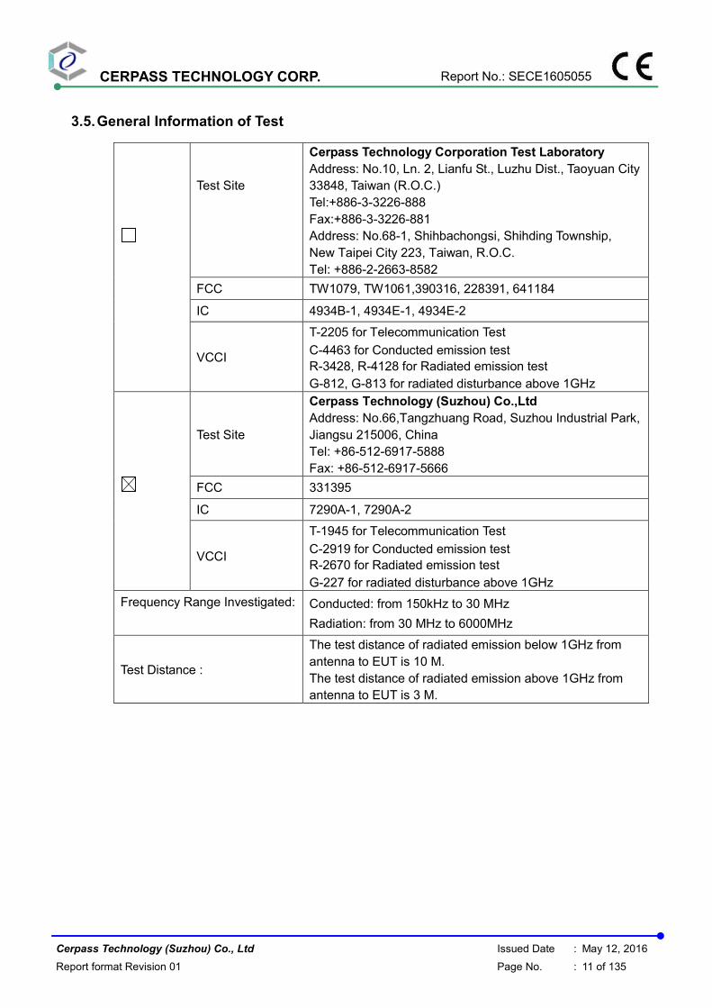
Test Mode : Mode 1: Full system for PI-SFW401L with Adapter #1 + POE
AC Power : AC 230V/50Hz Phase : NEUTRAL
Equipment : Network Dome Camera Model No : PI-SFW401L
Temperature : 23℃ Humidity : 55%
Pressure(mbar) : 1002 Date : 2015/06/10
No. Frequency
(MHz)
Factor
(dB)
Reading
(dBuV)
Level
(dBuV)
Limit
(dBuV)
Margin
(dB)
Detector
1 0.3260 10.24 42.22 52.46 59.55 -7.09 QP
2 0.3260 10.24 32.53 42.77 49.55 -6.78 AVG
3 0.6060 10.27 31.36 41.63 56.00 -14.37 QP
4 0.6060 10.27 20.98 31.25 46.00 -14.75 AVG
5 1.0900 10.34 32.11 42.45 56.00 -13.55 QP
6 1.0900 10.34 21.33 31.67 46.00 -14.33 AVG
7 1.4900 10.45 32.04 42.49 56.00 -13.51 QP
8 1.4900 10.45 21.02 31.47 46.00 -14.53 AVG
9 2.3620 10.50 31.71 42.21 56.00 -13.79 QP
10 2.3620 10.50 21.24 31.74 46.00 -14.26 AVG
11 4.0180 10.53 30.08 40.61 56.00 -15.39 QP
12 4.0180 10.53 19.96 30.49 46.00 -15.51 AVG
Note: Measurement Level = Reading Level + Correct Factor

CERPASS TECHNOLOGY CORP. Report No.: SECE1605055
Cerpass Technology (Suzhou) Co., Ltd Issued Date : May 12, 2016
Report format Revision 01 Page No. : 19 of 135
Test Mode : Mode 2: Full system for PI-SFW401L with Adapter #2 + POE
AC Power : AC 230V/50Hz Phase : LINE
Equipment : Network Dome Camera Model No : PI-SFW401L
Temperature : 23℃ Humidity : 55%
Pressure(mbar) : 1002 Date : 2015/06/10
No. Frequency
(MHz)
Factor
(dB)
Reading
(dBuV)
Level
(dBuV)
Limit
(dBuV)
Margin
(dB)
Detector
1 0.1980 10.25 20.62 30.87 63.69 -32.82 QP
2 0.1980 10.25 -0.78 9.47 53.69 -44.22 AVG
3 0.2180 10.25 19.04 29.29 62.89 -33.60 QP
4 0.2180 10.25 -1.26 8.99 52.89 -43.90 AVG
5 0.4660 10.29 18.87 29.16 56.58 -27.42 QP
6 0.4660 10.29 18.37 28.66 46.58 -17.92 AVG
7 0.6980 10.32 7.14 17.46 56.00 -38.54 QP
8 0.6980 10.32 4.00 14.32 46.00 -31.68 AVG
9 0.9300 10.31 12.10 22.41 56.00 -33.59 QP
10 0.9300 10.31 11.72 22.03 46.00 -23.97 AVG
11 26.0620 10.51 20.56 31.07 60.00 -28.93 QP
12 26.0620 10.51 16.26 26.77 50.00 -23.23 AVG
Note: Measurement Level = Reading Level + Correct Factor

CERPASS TECHNOLOGY CORP. Report No.: SECE1605055
Cerpass Technology (Suzhou) Co., Ltd Issued Date : May 12, 2016
Report format Revision 01 Page No. : 20 of 135
Test Mode : Mode 2: Full system for PI-SFW401L with Adapter #2 + POE
AC Power : AC 230V/50Hz Phase : NEUTRAL
Equipment : Network Dome Camera Model No : PI-SFW401L
Temperature : 23℃ Humidity : 55%
Pressure(mbar) : 1002 Date : 2015/06/10
No. Frequency
(MHz)
Factor
(dB)
Reading
(dBuV)
Level
(dBuV)
Limit
(dBuV)
Margin
(dB)
Detector
1 0.1539 10.20 20.89 31.09 65.78 -34.69 QP
2 0.1539 10.20 -0.10 10.10 55.78 -45.68 AVG
3 0.1940 10.21 20.52 30.73 63.86 -33.13 QP
4 0.1940 10.21 -0.81 9.40 53.86 -44.46 AVG
5 0.4660 10.25 16.38 26.63 56.58 -29.95 QP
6 0.4660 10.25 15.05 25.30 46.58 -21.28 AVG
7 0.9300 10.31 9.60 19.91 56.00 -36.09 QP
8 0.9300 10.31 8.84 19.15 46.00 -26.85 AVG
9 3.7060 10.53 -0.50 10.03 56.00 -45.97 QP
10 3.7060 10.53 -5.01 5.52 46.00 -40.48 AVG
11 26.2620 10.89 16.79 27.68 60.00 -32.32 QP
12 26.2620 10.89 12.17 23.06 50.00 -26.94 AVG
Note: Measurement Level = Reading Level + Correct Factor

CERPASS TECHNOLOGY CORP. Report No.: SECE1605055
Cerpass Technology (Suzhou) Co., Ltd Issued Date : May 12, 2016
Report format Revision 01 Page No. : 21 of 135
Test Mode : Mode 3: Full system for PI-SFW201L with Adapter #1 + POE
AC Power : AC 230V/50Hz Phase : LINE
Equipment : Network Dome Camera Model No : PI-SFW201L
Temperature : 23℃ Humidity : 55%
Pressure(mbar) : 1002 Date : 2015/06/10
No. Frequency
(MHz)
Factor
(dB)
Reading
(dBuV)
Level
(dBuV)
Limit
(dBuV)
Margin
(dB)
Detector
1 0.3220 10.27 46.13 56.40 59.65 -3.25 QP
2 0.3220 10.27 36.29 46.56 49.65 -3.09 AVG
3 0.5899 10.30 36.53 46.83 56.00 -9.17 QP
4 0.5899 10.30 26.57 36.87 46.00 -9.13 AVG
5 1.0780 10.31 37.00 47.31 56.00 -8.69 QP
6 1.0780 10.31 27.06 37.37 46.00 -8.63 AVG
7 1.5220 10.30 36.82 47.12 56.00 -8.88 QP
8 1.5220 10.30 27.26 37.56 46.00 -8.44 AVG
9 2.3900 10.30 36.66 46.96 56.00 -9.04 QP
10 2.3900 10.30 26.50 36.80 46.00 -9.20 AVG
11 3.1380 10.30 35.38 45.68 56.00 -10.32 QP
12 3.1380 10.30 24.43 34.73 46.00 -11.27 AVG
13 3.7140 10.29 35.89 46.18 56.00 -9.82 QP
14 3.7140 10.29 25.44 35.73 46.00 -10.27 AVG
15 5.0100 10.29 35.32 45.61 60.00 -14.39 QP
16 5.0100 10.29 25.24 35.53 50.00 -14.47 AVG
Note: Measurement Level = Reading Level + Correct Factor

CERPASS TECHNOLOGY CORP. Report No.: SECE1605055
Cerpass Technology (Suzhou) Co., Ltd Issued Date : May 12, 2016
Report format Revision 01 Page No. : 22 of 135
Test Mode : Mode 3: Full system for PI-SFW201L with Adapter #1 + POE
AC Power : AC 230V/50Hz Phase : NEUTRAL
Equipment : Network Dome Camera Model No : PI-SFW201L
Temperature : 23℃ Humidity : 55%
Pressure(mbar) : 1002 Date : 2015/06/10
No. Frequency
(MHz)
Factor
(dB)
Reading
(dBuV)
Level
(dBuV)
Limit
(dBuV)
Margin
(dB)
Detector
1 0.3260 10.24 42.09 52.33 59.55 -7.22 QP
2 0.3260 10.24 32.23 42.47 49.55 -7.08 AVG
3 0.5820 10.26 31.02 41.28 56.00 -14.72 QP
4 0.5820 10.26 20.95 31.21 46.00 -14.79 AVG
5 1.0980 10.34 31.80 42.14 56.00 -13.86 QP
6 1.0980 10.34 21.19 31.53 46.00 -14.47 AVG
7 1.9260 10.48 31.62 42.10 56.00 -13.90 QP
8 1.9260 10.48 21.03 31.51 46.00 -14.49 AVG
9 2.7180 10.51 30.03 40.54 56.00 -15.46 QP
10 2.7180 10.51 19.54 30.05 46.00 -15.95 AVG
11 4.4860 10.54 30.22 40.76 56.00 -15.24 QP
12 4.4860 10.54 20.70 31.24 46.00 -14.76 AVG
Note: Measurement Level = Reading Level + Correct Factor

CERPASS TECHNOLOGY CORP. Report No.: SECE1605055
Cerpass Technology (Suzhou) Co., Ltd Issued Date : May 12, 2016
Report format Revision 01 Page No. : 23 of 135
Test Mode : Mode 4: Full system for PI-SFW201L with Adapter #2 + POE
AC Power : AC 230V/50Hz Phase : LINE
Equipment : Network Dome Camera Model No : PI-SFW201L
Temperature : 23℃ Humidity : 55%
Pressure(mbar) : 1002 Date : 2015/06/10
No. Frequency
(MHz)
Factor
(dB)
Reading
(dBuV)
Level
(dBuV)
Limit
(dBuV)
Margin
(dB)
Detector
1 0.1980 10.25 20.43 30.68 63.69 -33.01 QP
2 0.1980 10.25 -0.84 9.41 53.69 -44.28 AVG
3 0.4740 10.29 19.24 29.53 56.44 -26.91 QP
4 0.4740 10.29 18.68 28.97 46.44 -17.47 AVG
5 0.7100 10.32 13.64 23.96 56.00 -32.04 QP
6 0.7100 10.32 10.07 20.39 46.00 -25.61 AVG
7 0.9500 10.31 14.31 24.62 56.00 -31.38 QP
8 0.9500 10.31 13.96 24.27 46.00 -21.73 AVG
9 1.8940 10.29 5.13 15.42 56.00 -40.58 QP
10 1.8940 10.29 2.27 12.56 46.00 -33.44 AVG
11 26.0580 10.51 22.13 32.64 60.00 -27.36 QP
12 26.0580 10.51 17.53 28.04 50.00 -21.96 AVG
Note: Measurement Level = Reading Level + Correct Factor

CERPASS TECHNOLOGY CORP. Report No.: SECE1605055
Cerpass Technology (Suzhou) Co., Ltd Issued Date : May 12, 2016
Report format Revision 01 Page No. : 24 of 135
Test Mode : Mode 4: Full system for PI-SFW201L with Adapter #2 + POE
AC Power : AC 230V/50Hz Phase : NEUTRAL
Equipment : Network Dome Camera Model No : PI-SFW201L
Temperature : 23℃ Humidity : 55%
Pressure(mbar) : 1002 Date : 2015/06/10
No. Frequency
(MHz)
Factor
(dB)
Reading
(dBuV)
Level
(dBuV)
Limit
(dBuV)
Margin
(dB)
Detector
1 0.1500 10.19 20.93 31.12 65.99 -34.87 QP
2 0.1500 10.19 0.20 10.39 55.99 -45.60 AVG
3 0.1860 10.20 20.62 30.82 64.21 -33.39 QP
4 0.1860 10.20 -0.73 9.47 54.21 -44.74 AVG
5 0.4740 10.25 16.37 26.62 56.44 -29.82 QP
6 0.4740 10.25 15.24 25.49 46.44 -20.95 AVG
7 0.9460 10.31 12.68 22.99 56.00 -33.01 QP
8 0.9460 10.31 12.15 22.46 46.00 -23.54 AVG
9 2.3699 10.50 5.98 16.48 56.00 -39.52 QP
10 2.3699 10.50 3.55 14.05 46.00 -31.95 AVG
11 26.2620 10.89 19.19 30.08 60.00 -29.92 QP
12 26.2620 10.89 15.18 26.07 50.00 -23.93 AVG
Note: Measurement Level = Reading Level + Correct Factor
Test engineer:

CERPASS TECHNOLOGY CORP. Report No.: SECE1605055
Cerpass Technology (Suzhou) Co., Ltd Issued Date : May 12, 2016
Report format Revision 01 Page No. : 25 of 135
4.5.2 Conducted Emission for Telecommunication Port Test Data
Test Mode : Mode 1: Full system for PI-SFW401L with Adapter #1 (LAN
10Mbps+POE)
AC Power : AC 230V/50Hz Phase : 10Mbps
Equipment : Network Dome Camera Model No : PI-SFW401L
Temperature : 23℃ Humidity : 55%
Pressure(mbar) : 1002 Date : 2015/06/10
No. Frequency
(MHz)
Factor
(dB)
Reading
(dBuV)
Level
(dBuV)
Limit
(dBuV)
Margin
(dB)
Detector
1 0.3260 19.62 56.58 76.20 78.97 -2.77 QP
2 0.3260 19.62 45.70 65.32 68.97 -3.65 AVG
3 0.6020 19.58 44.76 64.34 74.00 -9.66 QP
4 0.6020 19.58 35.08 54.66 64.00 -9.34 AVG
5 1.0620 19.29 43.50 62.79 74.00 -11.21 QP
6 1.0620 19.29 34.72 54.01 64.00 -9.99 AVG
7 1.4900 19.25 43.65 62.90 74.00 -11.10 QP
8 1.4900 19.25 34.31 53.56 64.00 -10.44 AVG
9 2.8460 19.34 43.67 63.01 74.00 -10.99 QP
10 2.8460 19.34 34.20 53.54 64.00 -10.46 AVG
11 4.2060 19.56 43.49 63.05 74.00 -10.95 QP
12 4.2060 19.56 33.99 53.55 64.00 -10.45 AVG
13 11.0860 19.56 29.62 49.18 74.00 -24.82 QP
14 11.0860 19.56 22.31 41.87 64.00 -22.13 AVG
15 26.4700 19.80 25.53 45.33 74.00 -28.67 QP
16 26.4700 19.80 21.26 41.06 64.00 -22.94 AVG
Note: Measurement Level = Reading Level + Correct Factor

CERPASS TECHNOLOGY CORP. Report No.: SECE1605055
Cerpass Technology (Suzhou) Co., Ltd Issued Date : May 12, 2016
Report format Revision 01 Page No. : 26 of 135
Test Mode : Mode 2: Full system for PI-SFW401L with Adapter #1 (LAN
100Mbps+POE)
AC Power : AC 230V/50Hz Phase : 100Mbps
Equipment : Network Dome Camera Model No : PI-SFW401L
Temperature : 23℃ Humidity : 55%
Pressure(mbar) : 1002 Date : 2015/06/10
No. Frequency
(MHz)
Factor
(dB)
Reading
(dBuV)
Level
(dBuV)
Limit
(dBuV)
Margin
(dB)
Detector
1 0.2380 19.62 49.31 68.93 81.48 -12.55 QP
2 0.2380 19.62 39.51 59.13 71.48 -12.35 AVG
3 0.3300 19.62 56.52 76.14 78.86 -2.72 QP
4 0.3300 19.62 46.88 66.50 68.86 -2.36 AVG
5 0.6100 19.58 44.27 63.85 74.00 -10.15 QP
6 0.6100 19.58 34.83 54.41 64.00 -9.59 AVG
7 1.1460 19.28 43.29 62.57 74.00 -11.43 QP
8 1.1460 19.28 33.70 52.98 64.00 -11.02 AVG
9 1.6740 19.23 40.08 59.31 74.00 -14.69 QP
10 1.6740 19.23 28.81 48.04 64.00 -15.96 AVG
11 2.4420 19.27 43.89 63.16 74.00 -10.84 QP
12 2.4420 19.27 34.52 53.79 64.00 -10.21 AVG
13 3.9820 19.52 41.93 61.45 74.00 -12.55 QP
14 3.9820 19.52 31.72 51.24 64.00 -12.76 AVG
15 15.0260 19.25 22.46 41.71 74.00 -32.29 QP
16 15.0260 19.25 11.71 30.96 64.00 -33.04 AVG
17 17.2220 19.39 22.24 41.63 74.00 -32.37 QP
18 17.2220 19.39 8.99 28.38 64.00 -35.62 AVG
19 26.0140 19.80 27.22 47.02 74.00 -26.98 QP
20 26.0140 19.80 13.64 33.44 64.00 -30.56 AVG
Note: Measurement Level = Reading Level + Correct Factor

CERPASS TECHNOLOGY CORP. Report No.: SECE1605055
Cerpass Technology (Suzhou) Co., Ltd Issued Date : May 12, 2016
Report format Revision 01 Page No. : 27 of 135
Test Mode : Mode 3: Full system for PI-SFW401L with Adapter #2 (LAN
10Mbps+POE)
AC Power : AC 230V/50Hz Phase : 10Mbps
Equipment : Network Dome Camera Model No : PI-SFW401L
Temperature : 23℃ Humidity : 55%
Pressure(mbar) : 1002 Date : 2015/06/10
No. Frequency
(MHz)
Factor
(dB)
Reading
(dBuV)
Level
(dBuV)
Limit
(dBuV)
Margin
(dB)
Detector
1 0.2340 19.62 30.45 50.07 81.60 -31.53 QP
2 0.2340 19.62 29.39 49.01 71.60 -22.59 AVG
3 0.4660 19.60 36.52 56.12 74.97 -18.85 QP
4 0.4660 19.60 36.40 56.00 64.97 -8.97 AVG
5 3.6940 19.48 24.53 44.01 74.00 -29.99 QP
6 3.6940 19.48 17.29 36.77 64.00 -27.23 AVG
7 6.3060 19.49 28.92 48.41 74.00 -25.59 QP
8 6.3060 19.49 20.90 40.39 64.00 -23.61 AVG
9 11.1980 19.55 20.58 40.13 74.00 -33.87 QP
10 11.1980 19.55 15.56 35.11 64.00 -28.89 AVG
11 25.4660 19.81 18.44 38.25 74.00 -35.75 QP
12 25.4660 19.81 15.61 35.42 64.00 -28.58 AVG
Note: Measurement Level = Reading Level + Correct Factor

CERPASS TECHNOLOGY CORP. Report No.: SECE1605055
Cerpass Technology (Suzhou) Co., Ltd Issued Date : May 12, 2016
Report format Revision 01 Page No. : 28 of 135
Test Mode : Mode 4: Full system for PI-SFW401L with Adapter #2 (LAN
100Mbps+POE)
AC Power : AC 230V/50Hz Phase : 100Mbps
Equipment : Network Dome Camera Model No : PI-SFW401L
Temperature : 23℃ Humidity : 55%
Pressure(mbar) : 1002 Date : 2015/06/10
No. Frequency
(MHz)
Factor
(dB)
Reading
(dBuV)
Level
(dBuV)
Limit
(dBuV)
Margin
(dB)
Detector
1 0.2340 19.62 31.20 50.82 81.60 -30.78 QP
2 0.2340 19.62 30.14 49.76 71.60 -21.84 AVG
3 0.4660 19.60 36.96 56.56 74.97 -18.41 QP
4 0.4660 19.60 36.84 56.44 64.97 -8.53 AVG
5 0.6980 19.56 24.79 44.35 74.00 -29.65 QP
6 0.6980 19.56 21.82 41.38 64.00 -22.62 AVG
7 13.5580 19.36 27.88 47.24 74.00 -26.76 QP
8 13.5580 19.36 2.69 22.05 64.00 -41.95 AVG
9 19.3580 19.54 29.21 48.75 74.00 -25.25 QP
10 19.3580 19.54 3.65 23.19 64.00 -40.81 AVG
11 26.0140 19.80 27.55 47.35 74.00 -26.65 QP
12 26.0140 19.80 8.65 28.45 64.00 -35.55 AVG
Note: Measurement Level = Reading Level + Correct Factor
CERPASS TECHNOLOGY CORP. Report No.: SECE1605055
Cerpass Technology (Suzhou) Co., Ltd Issued Date : May 12, 2016
Report format Revision 01 Page No. : 29 of 135
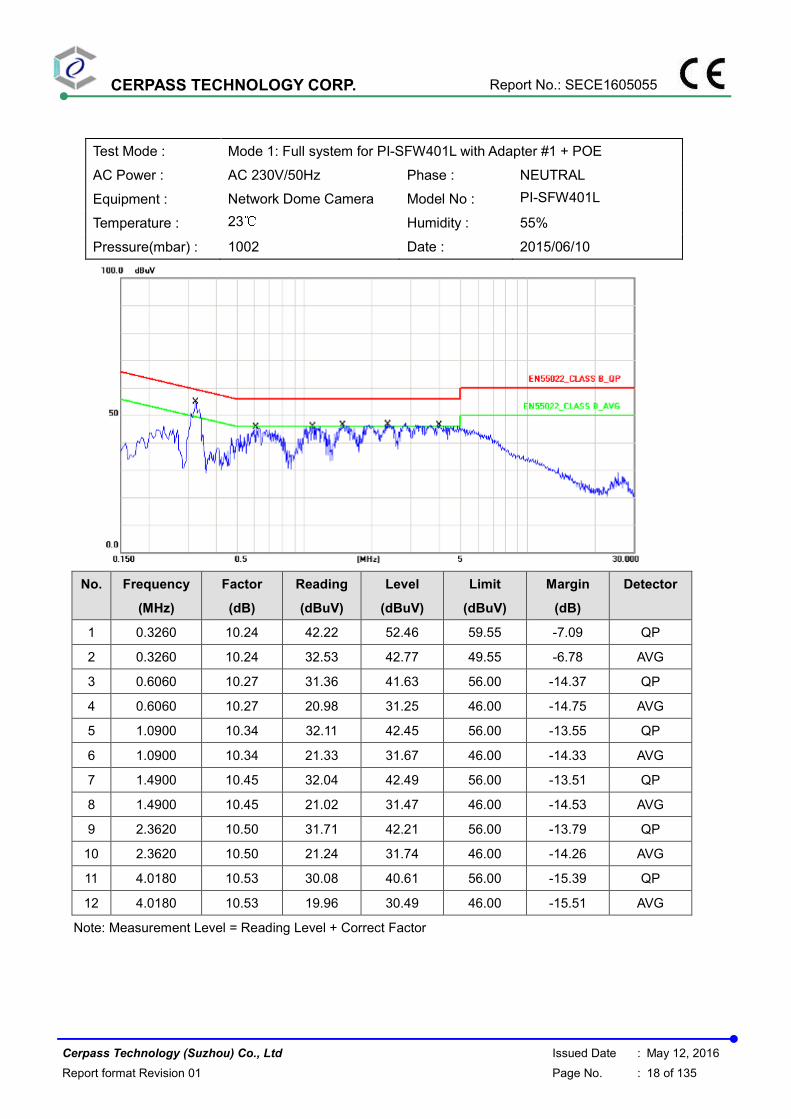
Test Mode : Mode 5: Full system for PI-SFW201L with Adapter #1 (LAN
10Mbps+POE)
AC Power : AC 230V/50Hz Phase : 10Mbps
Equipment : Network Dome Camera Model No : PI-SFW201L
Temperature : 23℃ Humidity : 55%
Pressure(mbar) : 1002 Date : 2015/06/10
No. Frequency
(MHz)
Factor
(dB)
Reading
(dBuV)
Level
(dBuV)
Limit
(dBuV)
Margin
(dB)
Detector
1 0.2380 19.62 49.94 69.56 81.48 -11.92 QP
2 0.2380 19.62 40.15 59.77 71.48 -11.71 AVG
3 0.3260 19.62 56.89 76.51 78.97 -2.46 QP
4 0.3260 19.62 47.09 66.71 68.97 -2.26 AVG
5 0.6220 19.58 45.63 65.21 74.00 -8.79 QP
6 0.6220 19.58 36.02 55.60 64.00 -8.40 AVG
7 1.0220 19.30 41.72 61.02 74.00 -12.98 QP
8 1.0220 19.30 32.97 52.27 64.00 -11.73 AVG
9 2.4300 19.27 40.72 59.99 74.00 -14.01 QP
10 2.4300 19.27 31.20 50.47 64.00 -13.53 AVG
11 3.9020 19.51 39.46 58.97 74.00 -15.03 QP
12 3.9020 19.51 29.29 48.80 64.00 -15.20 AVG
13 14.9460 19.25 20.93 40.18 74.00 -33.82 QP
14 14.9460 19.25 14.82 34.07 64.00 -29.93 AVG
15 26.6700 19.79 25.77 45.56 74.00 -28.44 QP
16 26.6700 19.79 23.49 43.28 64.00 -20.72 AVG
Note: Measurement Level = Reading Level + Correct Factor

CERPASS TECHNOLOGY CORP. Report No.: SECE1605055
Cerpass Technology (Suzhou) Co., Ltd Issued Date : May 12, 2016
Report format Revision 01 Page No. : 30 of 135
Test Mode : Mode 6: Full system for PI-SFW201L with Adapter #1 (LAN
100Mbps+POE)
AC Power : AC 230V/50Hz Phase : 100Mbps
Equipment : Network Dome Camera Model No : PI-SFW201L
Temperature : 23℃ Humidity : 55%
Pressure(mbar) : 1002 Date : 2015/06/10
No. Frequency
(MHz)
Factor
(dB)
Reading
(dBuV)
Level
(dBuV)
Limit
(dBuV)
Margin
(dB)
Detector
1 0.2380 19.62 49.73 69.35 81.48 -12.13 QP
2 0.2380 19.62 39.98 59.60 71.48 -11.88 AVG
3 0.3300 19.62 56.80 76.42 78.86 -2.44 QP
4 0.3300 19.62 46.83 66.45 68.86 -2.41 AVG
5 0.6020 19.58 46.07 65.65 74.00 -8.35 QP
6 0.6020 19.58 36.06 55.64 64.00 -8.36 AVG
7 1.0300 19.30 41.61 60.91 74.00 -13.09 QP
8 1.0300 19.30 32.07 51.37 64.00 -12.63 AVG
9 3.2580 19.41 40.45 59.86 74.00 -14.14 QP
10 3.2580 19.41 31.12 50.53 64.00 -13.47 AVG
11 15.0220 19.25 24.55 43.80 74.00 -30.20 QP
12 15.0220 19.25 10.40 29.65 64.00 -34.35 AVG
13 25.9540 19.80 23.26 43.06 74.00 -30.94 QP
14 25.9540 19.80 12.14 31.94 64.00 -32.06 AVG
Note: Measurement Level = Reading Level + Correct Factor
CERPASS TECHNOLOGY CORP. Report No.: SECE1605055
Cerpass Technology (Suzhou) Co., Ltd Issued Date : May 12, 2016
Report format Revision 01 Page No. : 31 of 135
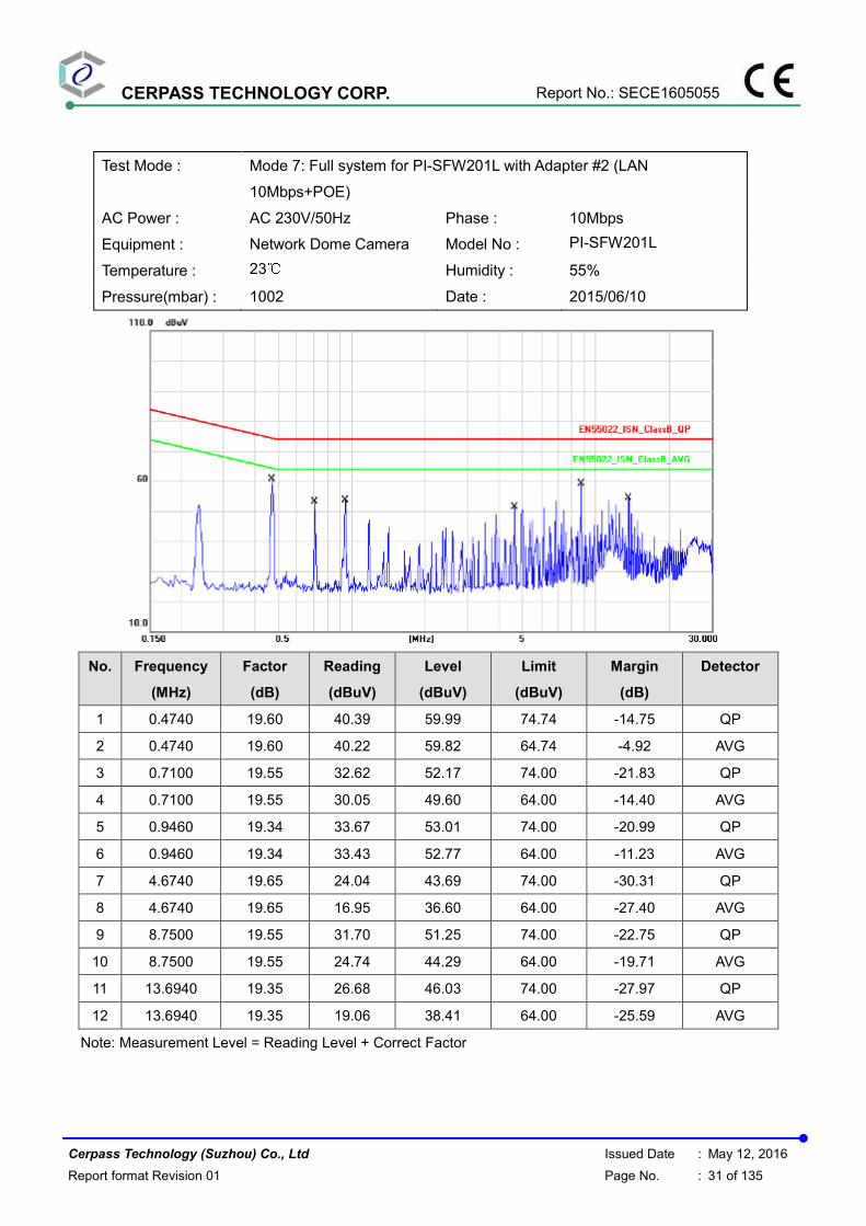
Test Mode : Mode 7: Full system for PI-SFW201L with Adapter #2 (LAN
10Mbps+POE)
AC Power : AC 230V/50Hz Phase : 10Mbps
Equipment : Network Dome Camera Model No : PI-SFW201L
Temperature : 23℃ Humidity : 55%
Pressure(mbar) : 1002 Date : 2015/06/10
No. Frequency
(MHz)
Factor
(dB)
Reading
(dBuV)
Level
(dBuV)
Limit
(dBuV)
Margin
(dB)
Detector
1 0.4740 19.60 40.39 59.99 74.74 -14.75 QP
2 0.4740 19.60 40.22 59.82 64.74 -4.92 AVG
3 0.7100 19.55 32.62 52.17 74.00 -21.83 QP
4 0.7100 19.55 30.05 49.60 64.00 -14.40 AVG
5 0.9460 19.34 33.67 53.01 74.00 -20.99 QP
6 0.9460 19.34 33.43 52.77 64.00 -11.23 AVG
7 4.6740 19.65 24.04 43.69 74.00 -30.31 QP
8 4.6740 19.65 16.95 36.60 64.00 -27.40 AVG
9 8.7500 19.55 31.70 51.25 74.00 -22.75 QP
10 8.7500 19.55 24.74 44.29 64.00 -19.71 AVG
11 13.6940 19.35 26.68 46.03 74.00 -27.97 QP
12 13.6940 19.35 19.06 38.41 64.00 -25.59 AVG
Note: Measurement Level = Reading Level + Correct Factor

CERPASS TECHNOLOGY CORP. Report No.: SECE1605055
Cerpass Technology (Suzhou) Co., Ltd Issued Date : May 12, 2016
Report format Revision 01 Page No. : 32 of 135
Test Mode : Mode 8: Full system for PI-SFW201L with Adapter #2 (LAN
100Mbps+POE)
AC Power : AC 230V/50Hz Phase : 100Mbps
Equipment : Network Dome Camera Model No : PI-SFW201L
Temperature : 23℃ Humidity : 55%
Pressure(mbar) : 1002 Date : 2015/06/10
No. Frequency
(MHz)
Factor
(dB)
Reading
(dBuV)
Level
(dBuV)
Limit
(dBuV)
Margin
(dB)
Detector
1 0.2380 19.62 32.01 51.63 81.48 -29.85 QP
2 0.2380 19.62 31.55 51.17 71.48 -20.31 AVG
3 0.4740 19.60 40.46 60.06 74.74 -14.68 QP
4 0.4740 19.60 40.29 59.89 64.74 -4.85 AVG
5 0.9500 19.34 32.64 51.98 74.00 -22.02 QP
6 0.9500 19.34 32.43 51.77 64.00 -12.23 AVG
7 8.1220 19.47 23.15 42.62 74.00 -31.38 QP
8 8.1220 19.47 0.52 19.99 64.00 -44.01 AVG
9 17.2220 19.39 29.18 48.57 74.00 -25.43 QP
10 17.2220 19.39 3.05 22.44 64.00 -41.56 AVG
11 25.3420 19.81 29.58 49.39 74.00 -24.61 QP
12 25.3420 19.81 9.49 29.30 64.00 -34.70 AVG
Note: Measurement Level = Reading Level + Correct Factor
Test engineer:
CERPASS TECHNOLOGY CORP. Report No.: SECE1605055
Cerpass Technology (Suzhou) Co., Ltd Issued Date : May 12, 2016
Report format Revision 01 Page No. : 33 of 135
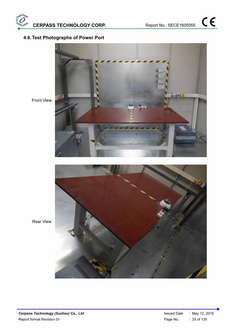
4.6. Test Photographs of Power Port
Front View
Rear View

CERPASS TECHNOLOGY CORP. Report No.: SECE1605055
Cerpass Technology (Suzhou) Co., Ltd Issued Date : May 12, 2016
Report format Revision 01 Page No. : 34 of 135
4.7. Test Photographs of Telecommunication Port
Front View
Rear View

CERPASS TECHNOLOGY CORP. Report No.: SECE1605055
Cerpass Technology (Suzhou) Co., Ltd Issued Date : May 12, 2016
Report format Revision 01 Page No. : 35 of 135
5. Test of Radiated Emission
5.1. Test Limit
The EUT shall meet the limits of below Table when measured at the measuring distance R in
accordance with the methods described in European Standard EN 55022 Clause 10. If the
reading on the measuring receiver shows fluctuations close to the limit, the reading shall be
observed for at least 15 s at each measurement frequency; the highest reading shall be
recorded, with the exception of any brief isolated high reading, which shall be ignored.
Table 1 – Limits for radiated disturbance at a measuring distance of 10 m (dB(µµµµV/m))
Frequency range(MHz) Class A Equipment Class B Equipment
Quasi-peak Quasi-peak
30 to 230 40 30
230 to 1000 47 37
NOTE 1 The lower limit shall apply at the transition frequency.
NOTE 2 Additional provisions may be required for cases where interference occurs.
The EUT shall meet the limits of below Table when measured in accordance with the method
described in European Standard EN 55022 Clause 10 and the conditional testing procedure
described below.
Table 2 – Limits for radiated disturbance at a measuring distance of 3 m (dB (µV/m))
Frequency range
(MHz)
Class A Equipment Class B Equipment
Avg. Peak Avg. Peak
1 to 3 56 76 50 70
3 to 6 60 80 54 74
NOTE The lower limit applies at the transition frequency. • Conditional testing procedure:
The highest internal source of an EUT is defined as the highest frequency generated or used
within the EUT or on which the EUT operates or tunes.
If the highest frequency of the internal sources of the EUT is less than 108 MHz, the
measurement shall only be made up to 1 GHz.
If the highest frequency of the internal sources of the EUT is between 108 MHz and 500 MHz,
the measurement shall only be made up to 2 GHz.
If the highest frequency of the internal sources of the EUT is between 500 MHz and 1 GHz,
the measurement shall only be made up to 5 GHz.
If the highest frequency of the internal sources of the EUT is above 1 GHz, the measurement
shall be made up to 5 times the highest frequency or 6 GHz, whichever is less.
CERPASS TECHNOLOGY CORP. Report No.: SECE1605055
Cerpass Technology (Suzhou) Co., Ltd Issued Date : May 12, 2016
Report format Revision 01 Page No. : 36 of 135
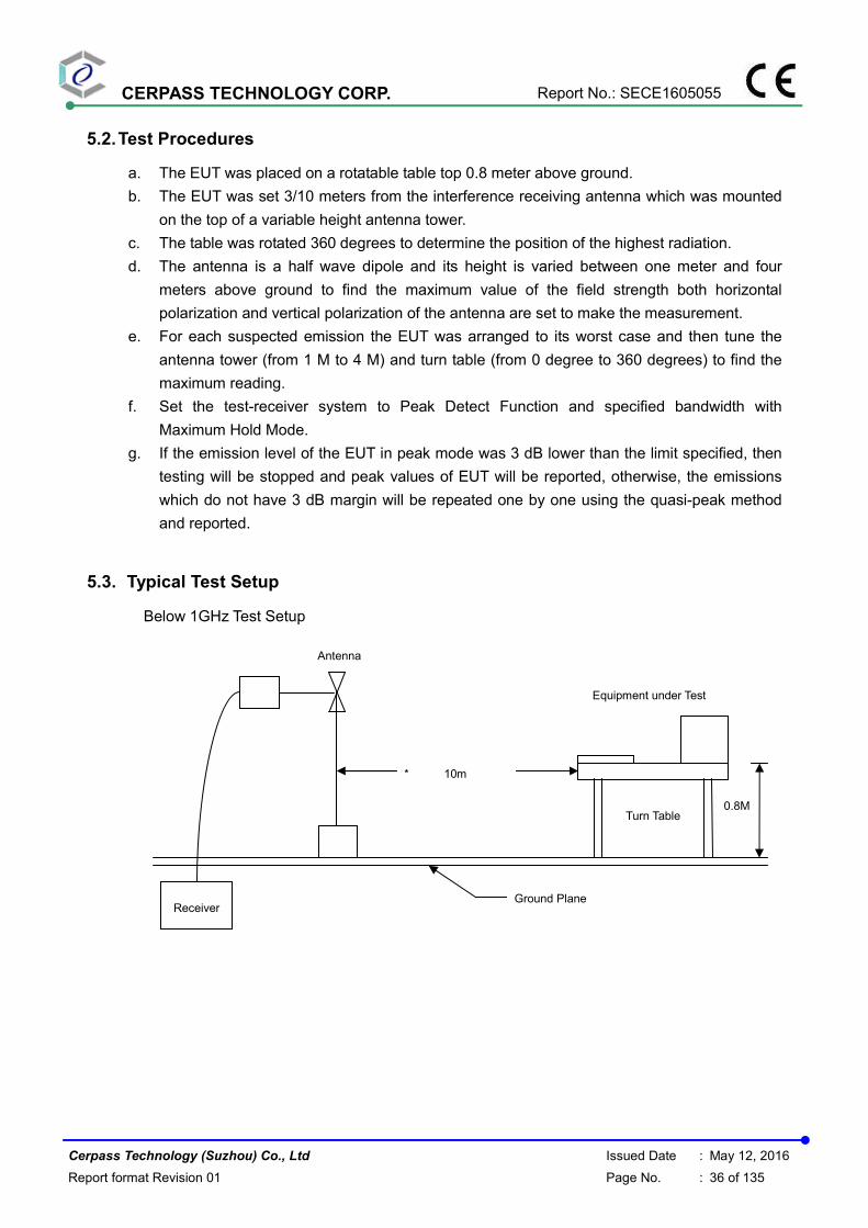
5.2. Test Procedures
a. The EUT was placed on a rotatable table top 0.8 meter above ground.
b. The EUT was set 3/10 meters from the interference receiving antenna which was mounted
on the top of a variable height antenna tower.
c. The table was rotated 360 degrees to determine the position of the highest radiation.
d. The antenna is a half wave dipole and its height is varied between one meter and four
meters above ground to find the maximum value of the field strength both horizontal
polarization and vertical polarization of the antenna are set to make the measurement.
e. For each suspected emission the EUT was arranged to its worst case and then tune the
antenna tower (from 1 M to 4 M) and turn table (from 0 degree to 360 degrees) to find the
maximum reading.
f. Set the test-receiver system to Peak Detect Function and specified bandwidth with
Maximum Hold Mode.
g. If the emission level of the EUT in peak mode was 3 dB lower than the limit specified, then
testing will be stopped and peak values of EUT will be reported, otherwise, the emissions
which do not have 3 dB margin will be repeated one by one using the quasi-peak method
and reported.
5.3. Typical Test Setup
Below 1GHz Test Setup
Turn Table
0.8M
Equipment under Test
Ground Plane Receiver
* 10m
Antenna
CERPASS TECHNOLOGY CORP. Report No.: SECE1605055
Cerpass Technology (Suzhou) Co., Ltd Issued Date : May 12, 2016
Report format Revision 01 Page No. : 37 of 135
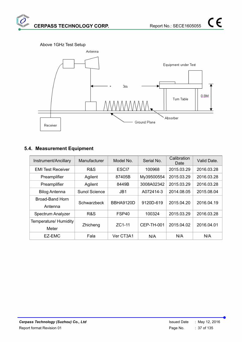
Above 1GHz Test Setup
5.4. Measurement Equipment
Instrument/Ancillary Manufacturer Model No. Serial No. Calibration
Date Valid Date.
EMI Test Receiver R&S ESCI7 100968 2015.03.29 2016.03.28
Preamplifier Agilent 87405B My39500554 2015.03.29 2016.03.28
Preamplifier Agilent 8449B 3008A02342 2015.03.29 2016.03.28
Bilog Antenna Sunol Science JB1 A072414-3 2014.08.05 2015.08.04
Broad-Band Horn
Antenna Schwarzbeck BBHA9120D 9120D-619 2015.04.20 2016.04.19
Spectrum Analyzer R&S FSP40 100324 2015.03.29 2016.03.28
Temperature/ Humidity
Meter Zhicheng ZC1-11 CEP-TH-001 2015.04.02 2016.04.01
EZ-EMC Fala Ver CT3A1 N/A N/A N/A

CERPASS TECHNOLOGY CORP. Report No.: SECE1605055
Cerpass Technology (Suzhou) Co., Ltd Issued Date : May 12, 2016
Report format Revision 01 Page No. : 38 of 135
5.5. Test Result and Data (30MHz ~ 1GHz)
Test Mode : Mode 1: Full system for PI-SFW401L with Adapter #1 + POE
AC Power : AC 230V/50Hz Ant. Polarization: Horizontal
Equipment : Network Dome Camera Model No : PI-SFW401L
Temp : 23℃ Humidity : 52%
Pressure(mbar) : 1002 Date : 2015/06/11
No. Frequency
(MHz)
Factor
(dB/m)
Reading
(dBuV)
Level
(dBuV/m)
Limit
(dBuV/m)
Margin
(dB)
Det. Height
(cm)
Azimuth
(deg)
1 163.8600 -11.11 29.97 18.86 30.00 -11.14 QP 100 336
2 245.3400 -9.26 31.32 22.06 37.00 -14.94 QP 100 9
3 324.8799 -7.17 30.51 23.34 37.00 -13.66 QP 200 226
4 450.0099 -3.69 30.37 26.68 37.00 -10.32 QP 200 115
5 650.7998 0.59 29.64 30.23 37.00 -6.77 QP 118 87
6 957.3200 5.12 26.86 31.98 37.00 -5.02 QP 400 124
Note: Measurement Level = Reading Level + Correct Factor

CERPASS TECHNOLOGY CORP. Report No.: SECE1605055
Cerpass Technology (Suzhou) Co., Ltd Issued Date : May 12, 2016
Report format Revision 01 Page No. : 39 of 135
Test Mode : Mode 1: Full system for PI-SFW401L with Adapter #1 + POE
AC Power : AC 230V/50Hz Ant. Polarization: Vertical
Equipment : Network Dome Camera Model No : PI-SFW401L
Temp : 23℃ Humidity : 52%
Pressure(mbar) : 1002 Date : 2015/06/11
No. Frequency
(MHz)
Factor
(dB/m)
Reading
(dBuV)
Level
(dBuV/m)
Limit
(dBuV/m)
Margin
(dB)
Det. Height
(cm)
Azimuth
(deg)
1 30.9699 -1.20 26.11 24.91 30.00 -5.09 QP 400 229
2 94.0199 -14.56 39.21 24.65 30.00 -5.35 QP 100 98
3 250.1899 -9.45 36.02 26.57 37.00 -10.43 QP 205 21
4 412.1800 -4.52 25.35 20.83 37.00 -16.17 QP 200 121
5 850.6200 3.77 27.09 30.86 37.00 -6.14 QP 200 87
6 979.6299 5.52 25.92 31.44 37.00 -5.56 QP 118 124
Note: Measurement Level = Reading Level + Correct Factor

CERPASS TECHNOLOGY CORP. Report No.: SECE1605055
Cerpass Technology (Suzhou) Co., Ltd Issued Date : May 12, 2016
Report format Revision 01 Page No. : 40 of 135
Test Mode : Mode 2: Full system for PI-SFW401L with Adapter #2 + POE
AC Power : AC 230V/50Hz Ant. Polarization: Horizontal
Equipment : Network Dome Camera Model No : PI-SFW401L
Temp : 23℃ Humidity : 52%
Pressure(mbar) : 1002 Date : 2015/06/11
No. Frequency
(MHz)
Factor
(dB/m)
Reading
(dBuV)
Level
(dBuV/m)
Limit
(dBuV/m)
Margin
(dB)
Det. Height
(cm)
Azimuth
(deg)
1 30.9700 -1.20 25.28 24.08 30.00 -5.92 QP 100 228
2 314.2100 -7.51 30.96 23.45 37.00 -13.55 QP 100 353
3 350.1000 -6.37 30.45 24.08 37.00 -12.92 QP 100 353
4 411.2100 -4.54 31.35 26.81 37.00 -10.19 QP 100 277
5 549.9200 -1.39 28.51 27.12 37.00 -9.88 QP 100 277
6 895.2400 4.08 26.29 30.37 37.00 -6.63 QP 100 286
Note: Measurement Level = Reading Level + Correct Factor

CERPASS TECHNOLOGY CORP. Report No.: SECE1605055
Cerpass Technology (Suzhou) Co., Ltd Issued Date : May 12, 2016
Report format Revision 01 Page No. : 41 of 135
Test Mode : Mode 2: Full system for PI-SFW401L with Adapter #2 + POE
AC Power : AC 230V/50Hz Ant. Polarization: Vertical
Equipment : Network Dome Camera Model No : PI-SFW401L
Temp : 23℃ Humidity : 52%
Pressure(mbar) : 1002 Date : 2015/06/11
No. Frequency
(MHz)
Factor
(dB/m)
Reading
(dBuV)
Level
(dBuV/m)
Limit
(dBuV/m)
Margin
(dB)
Det. Height
(cm)
Azimuth
(deg)
1 31.9400 -1.64 26.52 24.88 30.00 -5.12 QP 100 115
2 217.2100 -10.86 31.50 20.64 30.00 -9.36 QP 100 62
3 250.1899 -9.45 32.01 22.56 37.00 -14.44 QP 200 333
4 362.7099 -5.97 31.20 25.23 37.00 -11.77 QP 200 229
5 549.9199 -1.39 33.87 32.48 37.00 -4.52 QP 114 87
6 829.2799 3.63 26.03 29.66 37.00 -7.34 QP 400 154
Note: Measurement Level = Reading Level + Correct Factor

CERPASS TECHNOLOGY CORP. Report No.: SECE1605055
Cerpass Technology (Suzhou) Co., Ltd Issued Date : May 12, 2016
Report format Revision 01 Page No. : 42 of 135
Test Mode : Mode 3: Full system for PI-SFW401L with POE
DC Power : POE 48V Ant. Polarization: Horizontal
Equipment : Network Dome Camera Model No : PI-SFW401L
Temp : 23℃ Humidity : 52%
Pressure(mbar) : 1002 Date : 2015/06/11
No. Frequency
(MHz)
Factor
(dB/m)
Reading
(dBuV)
Level
(dBuV/m)
Limit
(dBuV/m)
Margin
(dB)
Det. Height
(cm)
Azimuth
(deg)
1 163.8600 -11.11 29.97 18.86 30.00 -11.14 QP 100 336
2 245.3400 -9.26 31.32 22.06 37.00 -14.94 QP 100 9
3 324.8798 -7.17 30.51 23.34 37.00 -13.66 QP 200 226
4 450.0099 -3.69 30.37 26.68 37.00 -10.32 QP 200 115
5 650.7998 0.59 29.64 30.23 37.00 -6.77 QP 118 87
6 957.3200 5.12 26.86 31.98 37.00 -5.02 QP 400 124
Note: Measurement Level = Reading Level + Correct Factor

CERPASS TECHNOLOGY CORP. Report No.: SECE1605055
Cerpass Technology (Suzhou) Co., Ltd Issued Date : May 12, 2016
Report format Revision 01 Page No. : 43 of 135
Test Mode : Mode 3: Full system for PI-SFW401L with POE
DC Power : POE 48V Ant. Polarization: Vertical
Equipment : Network Dome Camera Model No : PI-SFW401L
Temp : 23℃ Humidity : 52%
Pressure(mbar) : 1002 Date : 2015/06/11
No. Frequency
(MHz)
Factor
(dB/m)
Reading
(dBuV)
Level
(dBuV/m)
Limit
(dBuV/m)
Margin
(dB)
Det. Height
(cm)
Azimuth
(deg)
1 30.9699 -1.20 26.11 24.91 30.00 -5.09 QP 400 229
2 94.0199 -14.56 39.21 24.65 30.00 -5.35 QP 100 98
3 250.1899 -9.45 36.02 26.57 37.00 -10.43 QP 205 21
4 412.1800 -4.52 25.35 20.83 37.00 -16.17 QP 200 121
5 850.6200 3.77 27.09 30.86 37.00 -6.14 QP 200 87
6 979.6299 5.52 25.92 31.44 37.00 -5.56 QP 118 124
Note: Measurement Level = Reading Level + Correct Factor

CERPASS TECHNOLOGY CORP. Report No.: SECE1605055
Cerpass Technology (Suzhou) Co., Ltd Issued Date : May 12, 2016
Report format Revision 01 Page No. : 44 of 135
Test Mode : Mode 4: Full system for PI-SFW201L with Adapter #1 + POE
AC Power : AC 230V/50Hz Ant. Polarization: Horizontal
Equipment : Network Dome Camera Model No : PI-SFW201L
Temp : 23℃ Humidity : 52%
Pressure(mbar) : 1002 Date : 2015/06/11
No. Frequency
(MHz)
Factor
(dB/m)
Reading
(dBuV)
Level
(dBuV/m)
Limit
(dBuV/m)
Margin
(dB)
Det. Height
(cm)
Azimuth
(deg)
1 31.9400 -1.64 27.07 25.43 30.00 -4.57 QP 400 262
2 165.8000 -11.29 30.02 18.73 30.00 -11.27 QP 100 339
3 250.1897 -9.45 32.67 23.22 37.00 -13.78 QP 200 115
4 450.0099 -3.69 29.51 25.82 37.00 -11.18 QP 100 98
5 650.7998 0.59 28.58 29.17 37.00 -7.83 QP 100 7
6 966.0498 5.28 26.29 31.57 37.00 -5.43 QP 400 124
Note: Measurement Level = Reading Level + Correct Factor

CERPASS TECHNOLOGY CORP. Report No.: SECE1605055
Cerpass Technology (Suzhou) Co., Ltd Issued Date : May 12, 2016
Report format Revision 01 Page No. : 45 of 135
Test Mode : Mode 4: Full system for PI-SFW201L with Adapter #1 + POE
AC Power : AC 230V/50Hz Ant. Polarization: Vertical
Equipment : Network Dome Camera Model No : PI-SFW201L
Temp : 23℃ Humidity : 52%
Pressure(mbar) : 1002 Date : 2015/06/11
No. Frequency
(MHz)
Factor
(dB/m)
Reading
(dBuV)
Level
(dBuV/m)
Limit
(dBuV/m)
Margin
(dB)
Det. Height
(cm)
Azimuth
(deg)
1 30.0000 -0.76 26.29 25.53 30.00 -4.47 QP 100 99
2 46.4900 -8.49 32.76 24.27 30.00 -5.73 QP 200 125
3 88.2000 -15.31 41.22 25.91 30.00 -4.09 QP 100 87
4 250.1899 -9.45 35.22 25.77 37.00 -11.23 QP 141 118
5 650.7999 0.59 28.79 29.38 37.00 -7.62 QP 200 98
6 989.3300 5.69 26.30 31.99 37.00 -5.01 QP 187 125
Note: Measurement Level = Reading Level + Correct Factor

CERPASS TECHNOLOGY CORP. Report No.: SECE1605055
Cerpass Technology (Suzhou) Co., Ltd Issued Date : May 12, 2016
Report format Revision 01 Page No. : 46 of 135
Test Mode : Mode 5: Full system for PI-SFW201L with Adapter #2 + POE
AC Power : AC 230V/50Hz Ant. Polarization: Horizontal
Equipment : Network Dome Camera Model No : PI-SFW201L
Temp : 23℃ Humidity : 52%
Pressure(mbar) : 1002 Date : 2015/06/11
No. Frequency
(MHz)
Factor
(dB/m)
Reading
(dBuV)
Level
(dBuV/m)
Limit
(dBuV/m)
Margin
(dB)
Det. Height
(cm)
Azimuth
(deg)
1 31.9400 -1.64 25.33 23.69 30.00 -6.31 QP 200 8
2 166.7700 -11.38 35.36 23.98 30.00 -6.02 QP 100 225
3 350.1000 -6.37 35.75 29.38 37.00 -7.62 QP 100 92
4 405.3899 -4.66 37.74 33.08 37.00 -3.92 QP 400 228
5 549.9199 -1.39 33.03 31.64 37.00 -5.36 QP 100 87
6 950.5299 5.00 26.74 31.74 37.00 -5.26 QP 200 154
Note: Measurement Level = Reading Level + Correct Factor
CERPASS TECHNOLOGY CORP. Report No.: SECE1605055
Cerpass Technology (Suzhou) Co., Ltd Issued Date : May 12, 2016
Report format Revision 01 Page No. : 47 of 135
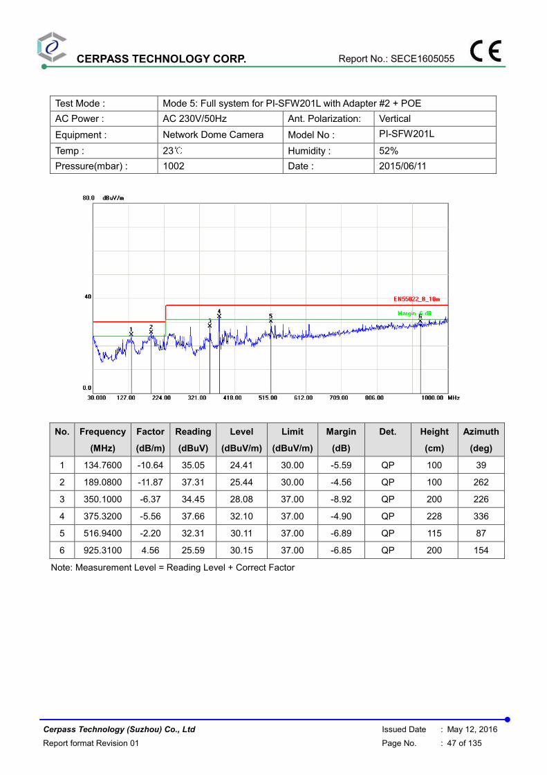
Test Mode : Mode 5: Full system for PI-SFW201L with Adapter #2 + POE
AC Power : AC 230V/50Hz Ant. Polarization: Vertical
Equipment : Network Dome Camera Model No : PI-SFW201L
Temp : 23℃ Humidity : 52%
Pressure(mbar) : 1002 Date : 2015/06/11
No. Frequency
(MHz)
Factor
(dB/m)
Reading
(dBuV)
Level
(dBuV/m)
Limit
(dBuV/m)
Margin
(dB)
Det. Height
(cm)
Azimuth
(deg)
1 134.7600 -10.64 35.05 24.41 30.00 -5.59 QP 100 39
2 189.0800 -11.87 37.31 25.44 30.00 -4.56 QP 100 262
3 350.1000 -6.37 34.45 28.08 37.00 -8.92 QP 200 226
4 375.3200 -5.56 37.66 32.10 37.00 -4.90 QP 228 336
5 516.9400 -2.20 32.31 30.11 37.00 -6.89 QP 115 87
6 925.3100 4.56 25.59 30.15 37.00 -6.85 QP 200 154
Note: Measurement Level = Reading Level + Correct Factor

CERPASS TECHNOLOGY CORP. Report No.: SECE1605055
Cerpass Technology (Suzhou) Co., Ltd Issued Date : May 12, 2016
Report format Revision 01 Page No. : 48 of 135
Test Mode : Mode 6: Full system for PI-SFW201L with POE
DC Power : POE 48V Ant. Polarization: Horizontal
Equipment : Network Dome Camera Model No : PI-SFW201L
Temp : 23℃ Humidity : 52%
Pressure(mbar) : 1002 Date : 2015/06/11
No. Frequency
(MHz)
Factor
(dB/m)
Reading
(dBuV)
Level
(dBuV/m)
Limit
(dBuV/m)
Margin
(dB)
Det. Height
(cm)
Azimuth
(deg)
1 30.9698 -1.20 26.35 25.15 30.00 -4.85 QP 100 20
2 250.1898 -9.45 32.33 22.88 37.00 -14.12 QP 100 336
3 533.4298 -1.79 26.83 25.04 37.00 -11.96 QP 100 115
4 549.9198 -1.39 29.39 28.00 37.00 -9.00 QP 200 262
5 650.7998 0.59 28.70 29.29 37.00 -7.71 QP 100 87
6 1000.0000 5.88 24.91 30.79 37.00 -6.21 QP 400 154
Note: Measurement Level = Reading Level + Correct Factor

CERPASS TECHNOLOGY CORP. Report No.: SECE1605055
Cerpass Technology (Suzhou) Co., Ltd Issued Date : May 12, 2016
Report format Revision 01 Page No. : 49 of 135
Test Mode : Mode 6: Full system for PI-SFW201L with POE
DC Power : POE 48V Ant. Polarization: Vertical
Equipment : Network Dome Camera Model No : PI-SFW201L
Temp : 23℃ Humidity : 52%
Pressure(mbar) : 1002 Date : 2015/06/11
No. Frequency
(MHz)
Factor
(dB/m)
Reading
(dBuV)
Level
(dBuV/m)
Limit
(dBuV/m)
Margin
(dB)
Det. Height
(cm)
Azimuth
(deg)
1 74.6200 -16.05 40.66 24.61 30.00 -5.39 QP 100 226
2 87.2300 -15.36 39.51 24.15 30.00 -5.85 QP 400 360
3 190.0500 -11.80 33.32 21.52 30.00 -8.48 QP 100 115
4 250.1898 -9.45 31.41 21.96 37.00 -15.04 QP 200 215
5 650.7998 0.59 28.93 29.52 37.00 -7.48 QP 200 8
6 984.4800 5.61 26.31 31.92 37.00 -5.08 QP 114 124
Note: Measurement Level = Reading Level + Correct Factor
Test engineer:

CERPASS TECHNOLOGY CORP. Report No.: SECE1605055
Cerpass Technology (Suzhou) Co., Ltd Issued Date : May 12, 2016
Report format Revision 01 Page No. : 50 of 135
5.6. Test Result and Data (1GHz ~ 6GHz)
Test Mode : Mode 1: Full system for PI-SFW401L with Adapter #1 + POE
AC Power : AC 230V/50Hz Ant. Polarization: Horizontal
Equipment : Network Dome Camera Model No : PI-SFW401L
Temp : 23℃ Humidity : 52%
Pressure(mbar) : 1002 Date : 2015/06/11
No. Frequency
(MHz)
Factor
(dB/m)
Reading
(dBuV)
Level
(dBuV/m)
Limit
(dBuV/m)
Margin
(dB)
Det. Height
(cm)
Azimuth
(deg)
1 1150.000 -14.80 53.50 38.70 70.00 -31.30 peak 100 243
2 1570.000 -12.11 47.13 35.02 70.00 -34.98 peak 100 4
3 1795.000 -10.64 50.67 40.03 70.00 -29.97 peak 100 349
4 2110.000 -6.73 52.41 45.68 70.00 -24.32 peak 100 236
5 2290.000 -3.20 44.96 41.76 70.00 -28.24 peak 100 140
6 3085.000 -2.41 45.28 42.87 74.00 -31.13 peak 100 89
Note: Measurement Level = Reading Level + Correct Factor

CERPASS TECHNOLOGY CORP. Report No.: SECE1605055
Cerpass Technology (Suzhou) Co., Ltd Issued Date : May 12, 2016
Report format Revision 01 Page No. : 51 of 135
Test Mode : Mode 1: Full system for PI-SFW401L with Adapter #1 + POE
AC Power : AC 230V/50Hz Ant. Polarization: Vertical
Equipment : Network Dome Camera Model No : PI-SFW401L
Temp : 23℃ Humidity : 52%
Pressure(mbar) : 1002 Date : 2015/06/11
No. Frequency
(MHz)
Factor
(dB/m)
Reading
(dBuV)
Level
(dBuV/m)
Limit
(dBuV/m)
Margin
(dB)
Det. Height
(cm)
Azimuth
(deg)
1 1150.000 -14.80 58.14 43.34 70.00 -26.66 peak 100 18
2 1760.000 -10.96 51.83 40.87 70.00 -29.13 peak 100 48
3 2050.000 -7.93 55.27 47.34 70.00 -22.66 peak 100 85
4 2110.000 -6.73 55.20 48.47 70.00 -21.53 peak 100 24
5 2465.000 -3.65 51.45 47.80 70.00 -22.20 peak 100 359
6 3170.000 -2.41 46.54 44.13 74.00 -29.87 peak 100 359
Note: Measurement Level = Reading Level + Correct Factor

CERPASS TECHNOLOGY CORP. Report No.: SECE1605055
Cerpass Technology (Suzhou) Co., Ltd Issued Date : May 12, 2016
Report format Revision 01 Page No. : 52 of 135
Test Mode : Mode 2: Full system for PI-SFW401L with Adapter #2 + POE
AC Power : AC 230V/50Hz Ant. Polarization: Horizontal
Equipment : Network Dome Camera Model No : PI-SFW401L
Temp : 23℃ Humidity : 52%
Pressure(mbar) : 1002 Date : 2015/06/11
No. Frequency
(MHz)
Factor
(dB/m)
Reading
(dBuV)
Level
(dBuV/m)
Limit
(dBuV/m)
Margin
(dB)
Det. Height
(cm)
Azimuth
(deg)
1 1025.000 -15.40 51.73 36.33 70.00 -33.67 peak 100 63
2 1150.000 -14.80 52.00 37.20 70.00 -32.80 peak 200 2
3 1795.000 -10.64 49.67 39.03 70.00 -30.97 peak 112 228
4 2110.000 -6.73 46.91 40.18 70.00 -29.82 peak 100 339
5 2290.000 -3.20 43.46 40.26 70.00 -29.74 peak 100 87
6 3025.000 -2.55 45.07 42.52 74.00 -31.48 peak 100 154
Note: Measurement Level = Reading Level + Correct Factor

CERPASS TECHNOLOGY CORP. Report No.: SECE1605055
Cerpass Technology (Suzhou) Co., Ltd Issued Date : May 12, 2016
Report format Revision 01 Page No. : 53 of 135
Test Mode : Mode 2: Full system for PI-SFW401L with Adapter #2 + POE
AC Power : AC 230V/50Hz Ant. Polarization: Vertical
Equipment : Network Dome Camera Model No : PI-SFW401L
Temp : 23℃ Humidity : 52%
Pressure(mbar) : 1002 Date : 2015/06/11
No. Frequency
(MHz)
Factor
(dB/m)
Reading
(dBuV)
Level
(dBuV/m)
Limit
(dBuV/m)
Margin
(dB)
Det. Height
(cm)
Azimuth
(deg)
1 1150.000 -14.80 56.14 41.34 70.00 -28.66 peak 200 39
2 1725.000 -11.28 50.72 39.44 70.00 -30.56 peak 200 228
3 1920.000 -9.67 50.58 40.91 70.00 -29.09 peak 100 282
4 2050.000 -7.93 51.27 43.34 70.00 -26.66 peak 114 226
5 2465.000 -3.65 48.45 44.80 70.00 -25.20 peak 100 87
6 2875.000 -4.18 46.93 42.75 70.00 -27.25 peak 100 124
Note: Measurement Level = Reading Level + Correct Factor

CERPASS TECHNOLOGY CORP. Report No.: SECE1605055
Cerpass Technology (Suzhou) Co., Ltd Issued Date : May 12, 2016
Report format Revision 01 Page No. : 54 of 135
Test Mode : Mode 3: Full system for PI-SFW401L with POE
DC Power : POE 48V Ant. Polarization: Horizontal
Equipment : Network Dome Camera Model No : PI-SFW401L
Temp : 23℃ Humidity : 52%
Pressure(mbar) : 1002 Date : 2015/06/11
No. Frequency
(MHz)
Factor
(dB/m)
Reading
(dBuV)
Level
(dBuV/m)
Limit
(dBuV/m)
Margin
(dB)
Det. Height
(cm)
Azimuth
(deg)
1 1025.000 -15.40 52.23 36.83 70.00 -33.17 peak 100 339
2 1150.000 -14.80 53.50 38.70 70.00 -31.30 peak 100 262
3 1795.000 -10.64 50.67 40.03 70.00 -29.97 peak 100 115
4 1915.000 -9.71 48.00 38.29 70.00 -31.71 peak 200 2
5 2110.000 -6.73 50.41 43.68 70.00 -26.32 peak 100 7
6 3085.000 -2.41 45.28 42.87 74.00 -31.13 peak 100 154
Note: Measurement Level = Reading Level + Correct Factor

CERPASS TECHNOLOGY CORP. Report No.: SECE1605055
Cerpass Technology (Suzhou) Co., Ltd Issued Date : May 12, 2016
Report format Revision 01 Page No. : 55 of 135
Test Mode : Mode 3: Full system for PI-SFW401L with POE
DC Power : POE 48V Ant. Polarization: Vertical
Equipment : Network Dome Camera Model No : PI-SFW401L
Temp : 23℃ Humidity : 52%
Pressure(mbar) : 1002 Date : 2015/06/11
No. Frequency
(MHz)
Factor
(dB/m)
Reading
(dBuV)
Level
(dBuV/m)
Limit
(dBuV/m)
Margin
(dB)
Det. Height
(cm)
Azimuth
(deg)
1 1150.000 -14.80 58.14 43.34 70.00 -26.66 peak 200 2
2 1760.000 -10.96 50.83 39.87 70.00 -30.13 peak 115 98
3 2050.000 -7.93 53.27 45.34 70.00 -24.66 peak 100 339
4 2110.000 -6.73 52.70 45.97 70.00 -24.03 peak 100 226
5 2465.000 -3.65 48.45 44.80 70.00 -25.20 peak 200 87
6 2875.000 -4.18 47.93 43.75 70.00 -26.25 peak 158 124
Note: Measurement Level = Reading Level + Correct Factor

CERPASS TECHNOLOGY CORP. Report No.: SECE1605055
Cerpass Technology (Suzhou) Co., Ltd Issued Date : May 12, 2016
Report format Revision 01 Page No. : 56 of 135
Test Mode : Mode 4: Full system for PI-SFW201L with Adapter #1 + POE
AC Power : AC 230V/50Hz Ant. Polarization: Horizontal
Equipment : Network Dome Camera Model No : PI-SFW201L
Temp : 23℃ Humidity : 52%
Pressure(mbar) : 1002 Date : 2015/06/11
No. Frequency
(MHz)
Factor
(dB/m)
Reading
(dBuV)
Level
(dBuV/m)
Limit
(dBuV/m)
Margin
(dB)
Det. Height
(cm)
Azimuth
(deg)
1 1000.0000 -15.51 55.13 39.62 70.00 -30.38 peak 100 91
2 1495.000 -12.38 48.33 35.95 70.00 -34.05 peak 100 16
3 1800.000 -10.59 48.83 38.24 70.00 -31.76 peak 100 92
4 2110.000 -6.73 49.99 43.26 70.00 -26.74 peak 100 211
5 2335.000 -3.05 45.46 42.41 70.00 -27.59 peak 100 40
6 3020.000 -2.56 45.17 42.61 74.00 -31.39 peak 100 176
Note: Measurement Level = Reading Level + Correct Factor

CERPASS TECHNOLOGY CORP. Report No.: SECE1605055
Cerpass Technology (Suzhou) Co., Ltd Issued Date : May 12, 2016
Report format Revision 01 Page No. : 57 of 135
Test Mode : Mode 4: Full system for PI-SFW201L with Adapter #1 + POE
AC Power : AC 230V/50Hz Ant. Polarization: Vertical
Equipment : Network Dome Camera Model No : PI-SFW201L
Temp : 23℃ Humidity : 52%
Pressure(mbar) : 1002 Date : 2015/06/11
No. Frequency
(MHz)
Factor
(dB/m)
Reading
(dBuV)
Level
(dBuV/m)
Limit
(dBuV/m)
Margin
(dB)
Det. Height
(cm)
Azimuth
(deg)
1 1075.000 -15.19 55.56 40.37 70.00 -29.63 peak 100 359
2 1350.000 -13.00 52.57 39.57 70.00 -30.43 peak 100 256
3 1815.000 -10.48 55.39 44.91 70.00 -25.09 peak 100 270
4 2110.000 -6.73 51.63 44.90 70.00 -25.10 peak 100 83
5 2815.000 -4.32 48.79 44.47 70.00 -25.53 peak 100 8
6 3100.000 -2.37 46.32 43.95 74.00 -30.05 peak 100 321
Note: Measurement Level = Reading Level + Correct Factor
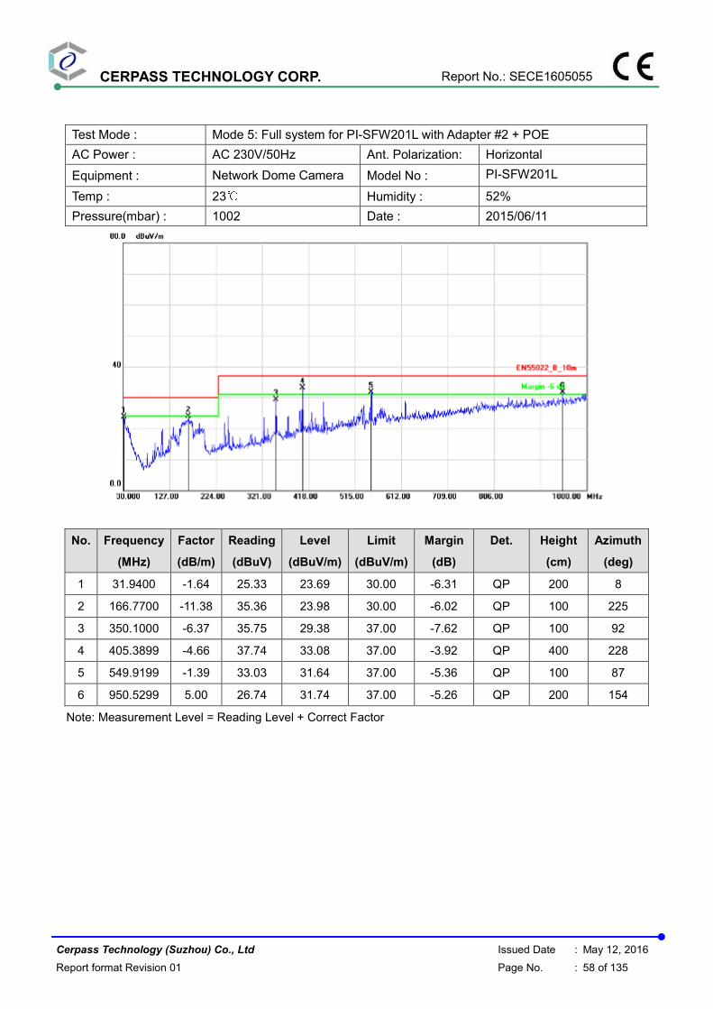
CERPASS TECHNOLOGY CORP. Report No.: SECE1605055
Cerpass Technology (Suzhou) Co., Ltd Issued Date : May 12, 2016
Report format Revision 01 Page No. : 58 of 135
Test Mode : Mode 5: Full system for PI-SFW201L with Adapter #2 + POE
AC Power : AC 230V/50Hz Ant. Polarization: Horizontal
Equipment : Network Dome Camera Model No : PI-SFW201L
Temp : 23℃ Humidity : 52%
Pressure(mbar) : 1002 Date : 2015/06/11
No. Frequency
(MHz)
Factor
(dB/m)
Reading
(dBuV)
Level
(dBuV/m)
Limit
(dBuV/m)
Margin
(dB)
Det. Height
(cm)
Azimuth
(deg)
1 31.9400 -1.64 25.33 23.69 30.00 -6.31 QP 200 8
2 166.7700 -11.38 35.36 23.98 30.00 -6.02 QP 100 225
3 350.1000 -6.37 35.75 29.38 37.00 -7.62 QP 100 92
4 405.3899 -4.66 37.74 33.08 37.00 -3.92 QP 400 228
5 549.9199 -1.39 33.03 31.64 37.00 -5.36 QP 100 87
6 950.5299 5.00 26.74 31.74 37.00 -5.26 QP 200 154
Note: Measurement Level = Reading Level + Correct Factor

CERPASS TECHNOLOGY CORP. Report No.: SECE1605055
Cerpass Technology (Suzhou) Co., Ltd Issued Date : May 12, 2016
Report format Revision 01 Page No. : 59 of 135
Test Mode : Mode 5: Full system for PI-SFW201L with Adapter #2 + POE
AC Power : AC 230V/50Hz Ant. Polarization: Vertical
Equipment : Network Dome Camera Model No : PI-SFW201L
Temp : 23℃ Humidity : 52%
Pressure(mbar) : 1002 Date : 2015/06/11
No. Frequency
(MHz)
Factor
(dB/m)
Reading
(dBuV)
Level
(dBuV/m)
Limit
(dBuV/m)
Margin
(dB)
Det. Height
(cm)
Azimuth
(deg)
1 134.7600 -10.64 35.05 24.41 30.00 -5.59 QP 100 39
2 189.0800 -11.87 37.31 25.44 30.00 -4.56 QP 100 262
3 350.1000 -6.37 34.45 28.08 37.00 -8.92 QP 200 226
4 375.3200 -5.56 37.66 32.10 37.00 -4.90 QP 228 336
5 516.9400 -2.20 32.31 30.11 37.00 -6.89 QP 115 87
6 925.3100 4.56 25.59 30.15 37.00 -6.85 QP 200 154
Note: Measurement Level = Reading Level + Correct Factor

CERPASS TECHNOLOGY CORP. Report No.: SECE1605055
Cerpass Technology (Suzhou) Co., Ltd Issued Date : May 12, 2016
Report format Revision 01 Page No. : 60 of 135
Test Mode : Mode 6: Full system for PI-SFW201L with POE
DC Power : POE 48V Ant. Polarization: Horizontal
Equipment : Network Dome Camera Model No : PI-SFW201L
Temp : 23℃ Humidity : 52%
Pressure(mbar) : 1002 Date : 2015/06/11
No. Frequency
(MHz)
Factor
(dB/m)
Reading
(dBuV)
Level
(dBuV/m)
Limit
(dBuV/m)
Margin
(dB)
Det. Height
(cm)
Azimuth
(deg)
1 1000.0000 -15.51 55.13 39.62 70.00 -30.38 peak 100 118
2 1075.000 -15.19 53.50 38.31 70.00 -31.69 peak 200 228
3 1505.000 -12.35 49.44 37.09 70.00 -32.91 peak 100 8
4 1710.000 -11.42 50.77 39.35 70.00 -30.65 peak 100 9
5 2110.000 -6.73 49.99 43.26 70.00 -26.74 peak 200 229
6 3020.000 -2.56 45.17 42.61 74.00 -31.39 peak 114 15
Note: Measurement Level = Reading Level + Correct Factor

CERPASS TECHNOLOGY CORP. Report No.: SECE1605055
Cerpass Technology (Suzhou) Co., Ltd Issued Date : May 12, 2016
Report format Revision 01 Page No. : 61 of 135
Test Mode : Mode 6: Full system for PI-SFW201L with POE
DC Power : POE 48V Ant. Polarization: Vertical
Equipment : Network Dome Camera Model No : PI-SFW201L
Temp : 23℃ Humidity : 52%
Pressure(mbar) : 1002 Date : 2015/06/11
No. Frequency
(MHz)
Factor
(dB/m)
Reading
(dBuV)
Level
(dBuV/m)
Limit
(dBuV/m)
Margin
(dB)
Det. Height
(cm)
Azimuth
(deg)
1 1075.000 -15.19 55.56 40.37 70.00 -29.63 peak 100 28
2 1350.000 -13.00 52.57 39.57 70.00 -30.43 peak 200 360
3 1815.000 -10.48 54.39 43.91 70.00 -26.09 peak 114 226
4 2110.000 -6.73 51.63 44.90 70.00 -25.10 peak 200 115
5 3035.000 -2.53 45.57 43.04 74.00 -30.96 peak 200 7
6 3695.000 -2.99 46.47 43.48 74.00 -30.52 peak 100 154
Note: Measurement Level = Reading Level + Correct Factor
Test engineer:
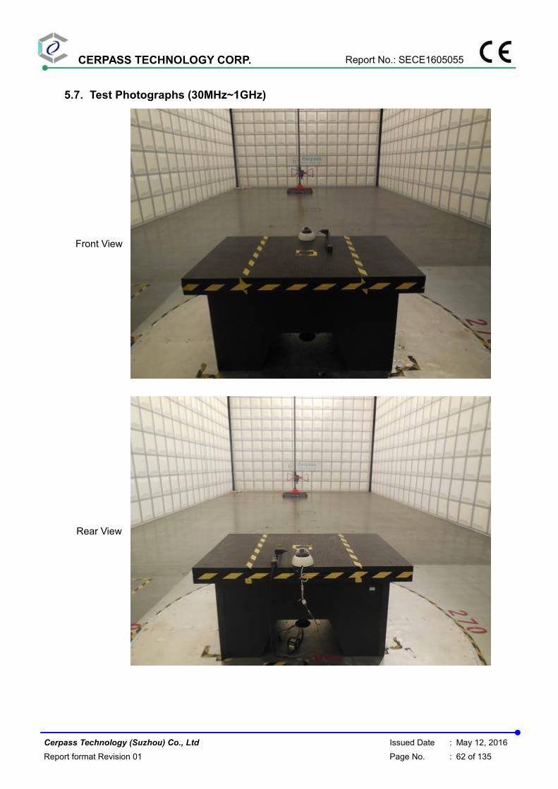
CERPASS TECHNOLOGY CORP. Report No.: SECE1605055
Cerpass Technology (Suzhou) Co., Ltd Issued Date : May 12, 2016
Report format Revision 01 Page No. : 62 of 135
5.7. Test Photographs (30MHz~1GHz)
Front View
Rear View

CERPASS TECHNOLOGY CORP. Report No.: SECE1605055
Cerpass Technology (Suzhou) Co., Ltd Issued Date : May 12, 2016
Report format Revision 01 Page No. : 63 of 135
5.8. Test Photographs (1GHz~6GHz)
Front View
Rear View

CERPASS TECHNOLOGY CORP. Report No.: SECE1605055
Cerpass Technology (Suzhou) Co., Ltd Issued Date : May 12, 2016
Report format Revision 01 Page No. : 64 of 135
6. Harmonics Test
6.1. Limits of Harmonics Current Measurement
Limits for Class A equipment
Harmonics Order n
Max. permissible harmonics current
A
Harmonics Order n
Max. permissible harmonics current
A
Odd harmonics Even harmonics
3 2.30 2 1.08
5 1.14 4 0.43
7 0.77 6 0.30
9 0.40 8<=n<=40 0.23x8/n
11 0.33
13 0.21
15<=n<=39 0.15x15/n
(b) Limits for Class B equipment For Class B equipment, the harmonics of the input current shall not exceed the values given in Table that is the limit of Class A multiplied by a factor of 1,5. (c) Limits for Class C equipment
Harmonics Order n
Maximum permissible harmonic current expressed as a percentage of the input current at the fundamental frequency
℅
2 2
3 30.λ*
5 10
7 7
9 5
11<n<39
(odd harmonics only) 3
* λ is the circuit power factor
(d) Limits for Class D equipment
Harmonics Order n
Maximum permissible harmonic current per watt
mA/W
Maximum permissible harmonic current
A
3 3.4 2.30
5 1.9 1.14
7 1.0 0.77
9 0.5 0.40
11 0.35 0.33
11 < n < 39 (odd harmonics only)
3.85/n See limit of Class A
NOTE: According to section 7 of EN 61000-3-2, the above limits for all equipment except for lighting equipment having an active input power > 75 W and no limits apply for equipment with an active input power up to and including 75 W.

CERPASS TECHNOLOGY CORP. Report No.: SECE1605055
Cerpass Technology (Suzhou) Co., Ltd Issued Date : May 12, 2016
Report format Revision 01 Page No. : 65 of 135
6.2. Measurement equipment
Instrument/Ancillary Manufacturer Model No. Serial No. Calibration
Date Valid Date.
EMC Emission Tester EMCPARTNE
R Harmonics-1000 159 2015.04.02 2016.04.01
Temperature/ Humidity Meter
Zhicheng ZC1-11 CEP-TH-004 2015.04.02 2016.04.01
POWER SOURCE Pacific 140AMX-UP12/S 1792 2014.09.04 2015.09.03
HARCS EMC Partner
AG Ver 4.18 N/A N/A N/A

CERPASS TECHNOLOGY CORP. Report No.: SECE1605055
Cerpass Technology (Suzhou) Co., Ltd Issued Date : May 12, 2016
Report format Revision 01 Page No. : 66 of 135
6.3. Test Result and Data
Basic Standard : EN 61000-3-2
Final Test Result : PASS
Test Mode : Mode 1
Equipment : Network Dome Camera
Model No. : PI-SFW401L
Temperature : 20℃
Humidity : 50 %
Atmospheric Pressure : 100 kPa
Test Date : Jun 09, 2015
Full Bar : Actual Values
Empty Bar : Maximum Values
Blue : Current , Green : Voltage , Red : Failed
Urms = 229.9V Freq = 50.013 Range: 0.5 A
Irms = 0.046A Ipk = 0.277A cf = 6.043
P = 3.767W S = 10.55VA pf = 0.357
THDi = 94.1 % THDu = 0.20 % Class A
Test - Time : 15min ( 100 %)
Test completed, Result: PASSED

CERPASS TECHNOLOGY CORP. Report No.: SECE1605055
Cerpass Technology (Suzhou) Co., Ltd Issued Date : May 12, 2016
Report format Revision 01 Page No. : 67 of 135
Order Freq. Irms Irms%L Imax Imax%L Limit [Hz] [A] [%] [A] [%] [A] 1 50 0.0165 0.0167 2 100 0.0002 0.0170 0.0004 0.0339 1.0800 3 150 0.0153 0.6634 0.0153 0.6661 2.3000 4 200 0.0002 0.0497 0.0003 0.0781 0.4300 5 250 0.0149 1.3090 0.0150 1.3198 1.1400 6 300 0.0002 0.0610 0.0004 0.1322 0.3000 7 350 0.0146 1.8984 0.0148 1.9182 0.7700 8 400 0.0002 0.0929 0.0004 0.1725 0.2300 9 450 0.0142 3.5553 0.0143 3.5706 0.4000 10 500 0.0002 0.1327 0.0004 0.2156 0.1840 11 550 0.0137 4.1430 0.0137 4.1615 0.3300 12 600 0.0002 0.1592 0.0004 0.2587 0.1533 13 650 0.0131 6.2198 0.0131 6.2488 0.2100 14 700 0.0003 0.2090 0.0004 0.3019 0.1314 15 750 0.0123 8.2194 0.0124 8.2601 0.1500 16 800 0.0003 0.2388 0.0004 0.3715 0.1150 17 850 0.0116 8.7389 0.0117 8.8081 0.1324 18 900 0.0003 0.2687 0.0004 0.4180 0.1022 19 950 0.0108 9.0970 0.0109 9.2000 0.1184 20 1000 0.0003 0.3317 0.0004 0.4644 0.0920 21 1050 0.0099 9.2855 0.0100 9.3709 0.1071 22 1100 0.0003 0.3284 0.0004 0.5108 0.0836 23 1150 0.0091 9.2963 0.0092 9.4211 0.0978 24 1200 0.0003 0.3981 0.0004 0.5573 0.0767 25 1250 0.0083 9.2231 0.0084 9.3248 0.0900 26 1300 0.0003 0.4312 0.0005 0.6468 0.0708 27 1350 0.0075 8.9722 0.0076 9.0820 0.0833 28 1400 0.0003 0.4180 0.0004 0.6502 0.0657 29 1450 0.0067 8.6534 0.0068 8.7714 0.0776 30 1500 0.0003 0.4478 0.0004 0.6966 0.0613 31 1550 0.0060 8.2831 0.0061 8.3672 0.0726 32 1600 0.0003 0.4777 0.0004 0.7430 0.0575 33 1650 0.0053 7.8328 0.0054 7.8776 0.0682 34 1700 0.0002 0.4511 0.0004 0.7331 0.0541 35 1750 0.0047 7.3581 0.0048 7.4056 0.0643 36 1800 0.0002 0.4777 0.0004 0.7762 0.0511 37 1850 0.0042 6.8251 0.0042 6.9255 0.0608 38 1900 0.0002 0.5042 0.0004 0.7563 0.0484 39 1950 0.0037 6.4006 0.0038 6.5063 0.0577 40 2000 0.0002 0.4644 0.0003 0.7298 0.0460
EUT is PASSED if:
- all Average values of the Individual Harmonic Currents (Iavg)
are below 100% of the Individual Limits.
- all Maximum values of the Individual Harmonic Currents (Imax)
are below 150% of the Individual Limits.

CERPASS TECHNOLOGY CORP. Report No.: SECE1605055
Cerpass Technology (Suzhou) Co., Ltd Issued Date : May 12, 2016
Report format Revision 01 Page No. : 68 of 135
Basic Standard : EN 61000-3-2
Final Test Result : PASS
Test Mode : Mode 2
Equipment : Network Dome Camera
Model No. : PI-SFW401L
Temperature : 20℃
Humidity : 50 %
Atmospheric Pressure : 100 kPa
Test Date : Jun 24, 2015
Full Bar : Actual Values
Empty Bar : Maximum Values
Blue : Current , Green : Voltage , Red : Failed
Urms = 229.9V Freq = 50.000 Range: 0.5 A
Irms = 0.080A Ipk = 0.181A cf = 2.279
P = 6.663W S = 18.30VA pf = 0.364
THDi = 50.2 % THDu = 0.20 % Class A
Test - Time : 15min ( 100 %)
Test completed, Result: PASSED

CERPASS TECHNOLOGY CORP. Report No.: SECE1605055
Cerpass Technology (Suzhou) Co., Ltd Issued Date : May 12, 2016
Report format Revision 01 Page No. : 69 of 135
Order Freq. Irms Irms%L Imax Imax%L Limit [Hz] [A] [%] [A] [%] [A] 1 50 0.0689 0.0827 2 100 0.0002 0.0226 0.0005 0.0452 1.0800 3 150 0.0312 1.3560 0.0374 1.6254 2.3000 4 200 0.0001 0.0284 0.0004 0.0852 0.4300 5 250 0.0232 2.0372 0.0279 2.4468 1.1400 6 300 0.0001 0.0305 0.0003 0.0916 0.3000 7 350 0.0049 0.6302 0.0058 0.7491 0.7700 8 400 0.0001 0.0265 0.0002 0.0796 0.2300 9 450 0.0075 1.8692 0.0091 2.2659 0.4000 10 500 0.0001 0.0332 0.0002 0.0829 0.1840 11 550 0.0005 0.1480 0.0006 0.1942 0.3300 12 600 0.0001 0.0398 0.0001 0.0796 0.1533 13 650 0.0009 0.4360 0.0012 0.5522 0.2100 14 700 0.0001 0.0464 0.0001 0.0697 0.1314 15 750 0.0007 0.4883 0.0009 0.6104 0.1500 16 800 0.0001 0.0531 0.0001 0.1061 0.1150 17 850 0.0008 0.6226 0.0010 0.7609 0.1324 18 900 0.0001 0.0597 0.0001 0.0896 0.1022 19 950 0.0002 0.2062 0.0004 0.3092 0.1184 20 1000 0.0001 0.0663 0.0001 0.0995 0.0920 21 1050 0.0002 0.2279 0.0003 0.3133 0.1071 22 1100 0.0001 0.0730 0.0001 0.1095 0.0836 23 1150 0.0003 0.3120 0.0004 0.4055 0.0978 24 1200 0.0001 0.0796 0.0001 0.1194 0.0767 25 1250 0.0003 0.3052 0.0003 0.3730 0.0900 26 1300 0.0001 0.0862 0.0001 0.1294 0.0708 27 1350 0.0002 0.2197 0.0002 0.2563 0.0833 28 1400 0.0001 0.0929 0.0001 0.1393 0.0657 29 1450 0.0002 0.1967 0.0002 0.2753 0.0776 30 1500 0.0001 0.0995 0.0001 0.1493 0.0613 31 1550 0.0002 0.2523 0.0002 0.3364 0.0726 32 1600 0.0001 0.1061 0.0001 0.1592 0.0575 33 1650 0.0001 0.1790 0.0002 0.2686 0.0682 34 1700 0.0001 0.1692 0.0001 0.2256 0.0541 35 1750 0.0002 0.2374 0.0002 0.2848 0.0643 36 1800 0.0001 0.1791 0.0001 0.2388 0.0511 37 1850 0.0002 0.2509 0.0002 0.3011 0.0608 38 1900 0.0001 0.1891 0.0001 0.2521 0.0484 39 1950 0.0002 0.2645 0.0002 0.3174 0.0577 40 2000 0.0001 0.2654 0.0001 0.2654 0.0460
EUT is PASSED if:
- all Average values of the Individual Harmonic Currents (Iavg)
are below 100% of the Individual Limits.
- all Maximum values of the Individual Harmonic Currents (Imax)
are below 150% of the Individual Limits.

CERPASS TECHNOLOGY CORP. Report No.: SECE1605055
Cerpass Technology (Suzhou) Co., Ltd Issued Date : May 12, 2016
Report format Revision 01 Page No. : 70 of 135
Basic Standard : EN 61000-3-2
Final Test Result : PASS
Test Mode : Mode 3
Equipment : Network Dome Camera
Model No. : PI-SFW201L
Temperature : 20℃
Humidity : 50 %
Atmospheric Pressure : 100 kPa
Test Date : Jun 09, 2015
Full Bar : Actual Values
Empty Bar : Maximum Values
Blue : Current , Green : Voltage , Red : Failed
Urms = 229.9V Freq = 50.013 Range: 0.5 A
Irms = 0.046A Ipk = 0.284A cf = 6.159
P = 3.780W S = 10.61VA pf = 0.356
THDi = 94.1 % THDu = 0.20 % Class A
Test - Time : 15min ( 100 %)
Test completed, Result: PASSED

CERPASS TECHNOLOGY CORP. Report No.: SECE1605055
Cerpass Technology (Suzhou) Co., Ltd Issued Date : May 12, 2016
Report format Revision 01 Page No. : 71 of 135
Order Freq. Irms Irms%L Imax Imax%L Limit [Hz] [A] [%] [A] [%] [A] 1 50 0.0166 0.0236 2 100 0.0004 0.0396 0.0005 0.0480 1.0800 3 150 0.0153 0.6661 0.0223 0.9686 2.3000 4 200 0.0004 0.0994 0.0005 0.1207 0.4300 5 250 0.0150 1.3171 0.0216 1.8953 1.1400 6 300 0.0005 0.1526 0.0005 0.1831 0.3000 7 350 0.0147 1.9103 0.0208 2.6951 0.7700 8 400 0.0005 0.1990 0.0005 0.2388 0.2300 9 450 0.0143 3.5782 0.0197 4.9133 0.4000 10 500 0.0005 0.2488 0.0005 0.2985 0.1840 11 550 0.0138 4.1707 0.0183 5.5487 0.3300 12 600 0.0005 0.2985 0.0006 0.3782 0.1533 13 650 0.0132 6.2634 0.0168 8.0218 0.2100 14 700 0.0005 0.3715 0.0006 0.4412 0.1314 15 750 0.0124 8.2804 0.0153 10.193 0.1500 16 800 0.0005 0.4246 0.0006 0.5307 0.1150 17 850 0.0117 8.8081 0.0137 10.353 0.1324 18 900 0.0005 0.4777 0.0006 0.5971 0.1022 19 950 0.0109 9.1743 0.0122 10.308 0.1184 20 1000 0.0005 0.5639 0.0006 0.6634 0.0920 21 1050 0.0100 9.3709 0.0108 10.111 0.1071 22 1100 0.0005 0.6203 0.0006 0.7663 0.0836 23 1150 0.0092 9.4211 0.0096 9.8579 0.0978 24 1200 0.0005 0.6767 0.0006 0.8359 0.0767 25 1250 0.0084 9.3248 0.0086 9.5961 0.0900 26 1300 0.0005 0.7331 0.0006 0.9056 0.0708 27 1350 0.0076 9.1187 0.0078 9.4116 0.0833 28 1400 0.0005 0.7895 0.0006 0.9288 0.0657 29 1450 0.0068 8.7714 0.0072 9.2828 0.0776 30 1500 0.0005 0.8459 0.0006 0.9951 0.0613 31 1550 0.0061 8.3672 0.0067 9.1661 0.0726 32 1600 0.0005 0.8492 0.0006 1.0084 0.0575 33 1650 0.0054 7.8776 0.0062 9.0861 0.0682 34 1700 0.0005 0.8459 0.0006 1.0714 0.0541 35 1750 0.0048 7.4056 0.0057 8.8772 0.0643 36 1800 0.0005 0.8956 0.0005 1.0747 0.0511 37 1850 0.0042 6.8753 0.0052 8.6317 0.0608 38 1900 0.0004 0.8824 0.0005 1.0714 0.0484 39 1950 0.0037 6.3477 0.0047 8.1991 0.0577 40 2000 0.0004 0.8625 0.0005 1.0615 0.0460
EUT is PASSED if:
- all Average values of the Individual Harmonic Currents (Iavg)
are below 100% of the Individual Limits.
- all Maximum values of the Individual Harmonic Currents (Imax)
are below 150% of the Individual Limits.

CERPASS TECHNOLOGY CORP. Report No.: SECE1605055
Cerpass Technology (Suzhou) Co., Ltd Issued Date : May 12, 2016
Report format Revision 01 Page No. : 72 of 135
Basic Standard : EN 61000-3-2
Final Test Result : PASS
Test Mode : Mode 4
Equipment : Network Dome Camera
Model No. : PI-SFW201L
Temperature : 20℃
Humidity : 50 %
Atmospheric Pressure : 100 kPa
Test Date : Jun 24, 2015
Full Bar : Actual Values
Empty Bar : Maximum Values
Blue : Current , Green : Voltage , Red : Failed
Urms = 229.9V Freq = 50.000 Range: 0.5 A
Irms = 0.079A Ipk = 0.181A cf = 2.284
P = 6.688W S = 18.19VA pf = 0.368
THDi = 49.9 % THDu = 0.20 % Class A
Test - Time : 15min ( 100 %)
Test completed, Result: PASSED

CERPASS TECHNOLOGY CORP. Report No.: SECE1605055
Cerpass Technology (Suzhou) Co., Ltd Issued Date : May 12, 2016
Report format Revision 01 Page No. : 73 of 135
Order Freq. Irms Irms%L Imax Imax%L Limit [Hz] [A] [%] [A] [%] [A] 1 50 0.0687 0.0687 2 100 0.0002 0.0226 0.0003 0.0311 1.0800 3 150 0.0308 1.3375 0.0308 1.3375 2.3000 4 200 0.0002 0.0497 0.0003 0.0639 0.4300 5 250 0.0231 2.0292 0.0231 2.0292 1.1400 6 300 0.0001 0.0407 0.0002 0.0610 0.3000 7 350 0.0047 0.6064 0.0047 0.6064 0.7700 8 400 0.0001 0.0398 0.0001 0.0531 0.2300 9 450 0.0076 1.8921 0.0076 1.9073 0.4000 10 500 0.0001 0.0332 0.0001 0.0663 0.1840 11 550 0.0004 0.1295 0.0005 0.1387 0.3300 12 600 0.0001 0.0398 0.0001 0.0597 0.1533 13 650 0.0009 0.4505 0.0010 0.4650 0.2100 14 700 0.0001 0.0464 0.0001 0.0697 0.1314 15 750 0.0008 0.5086 0.0008 0.5086 0.1500 16 800 0.0001 0.0531 0.0001 0.0796 0.1150 17 850 0.0008 0.6226 0.0009 0.6687 0.1324 18 900 0.0001 0.0597 0.0001 0.0896 0.1022 19 950 0.0003 0.2319 0.0003 0.2577 0.1184 20 1000 0.0001 0.0663 0.0001 0.0995 0.0920 21 1050 0.0003 0.2563 0.0003 0.2848 0.1071 22 1100 0.0001 0.0730 0.0001 0.1095 0.0836 23 1150 0.0003 0.3120 0.0003 0.3432 0.0978 24 1200 0.0001 0.0796 0.0001 0.1194 0.0767 25 1250 0.0002 0.2713 0.0003 0.3391 0.0900 26 1300 0.0001 0.1294 0.0001 0.1294 0.0708 27 1350 0.0002 0.1831 0.0002 0.2563 0.0833 28 1400 0.0001 0.0929 0.0001 0.1393 0.0657 29 1450 0.0002 0.1967 0.0002 0.2360 0.0776 30 1500 0.0001 0.0995 0.0001 0.1493 0.0613 31 1550 0.0002 0.2523 0.0002 0.2943 0.0726 32 1600 0.0001 0.1061 0.0001 0.1592 0.0575 33 1650 0.0002 0.2238 0.0002 0.2686 0.0682 34 1700 0.0001 0.1692 0.0001 0.1692 0.0541 35 1750 0.0001 0.1899 0.0002 0.2374 0.0643 36 1800 0.0001 0.1791 0.0001 0.2388 0.0511 37 1850 0.0001 0.2007 0.0002 0.2509 0.0608 38 1900 0.0001 0.1891 0.0001 0.2521 0.0484 39 1950 0.0001 0.2116 0.0002 0.2645 0.0577 40 2000 0.0001 0.1990 0.0001 0.2654 0.0460
EUT is PASSED if:
- all Average values of the Individual Harmonic Currents (Iavg)
are below 100% of the Individual Limits.
- all Maximum values of the Individual Harmonic Currents (Imax)
are below 150% of the Individual Limits.
Test engineer:

CERPASS TECHNOLOGY CORP. Report No.: SECE1605055
Cerpass Technology (Suzhou) Co., Ltd Issued Date : May 12, 2016
Report format Revision 01 Page No. : 74 of 135
6.4. Test Photographs

CERPASS TECHNOLOGY CORP. Report No.: SECE1605055
Cerpass Technology (Suzhou) Co., Ltd Issued Date : May 12, 2016
Report format Revision 01 Page No. : 75 of 135
7. Voltage Fluctuations Test
7.1. Test Procedure
The equipment shall be tested under the conditions of Clause 5.
The total impedance of the test circuit, excluding the appliance under test, but including the
internal impedance of the supply source, shall be equal to the reference impedance.
The stability and tolerance of the reference impedance shall be adequate to ensure that the
overall accuracy of ±8% is achieved during the whole assessment procedure.
7.2. Measurement Equipment
Instrument Manufacturer Model No. Serial No. Calibration Date Valid Date
EMC Emission Tester EMCPARTNE
R Harmonics-10
00 159 2015.04.02 2016.04.01
Temperature/ Humidity Meter
Zhicheng ZC1-11 CEP-TH-004 2015.04.02 2016.04.01
POWER SOURCE Pacific 140AMX-UP1
2/S 1792 2014.09.04 2015.09.03
HARCS EMC Partner
AG Ver 4.18 N/A N/A N/A

CERPASS TECHNOLOGY CORP. Report No.: SECE1605055
Cerpass Technology (Suzhou) Co., Ltd Issued Date : May 12, 2016
Report format Revision 01 Page No. : 76 of 135
7.3. Test Result and Data
Basic Standard : EN 61000-3-3
Final Test Result : PASS
Test Mode : Mode 1
Equipment : Network Dome Camera
Model No. : PI-SFW401L
Temperature : 20℃
Humidity : 50 %
Atmospheric Pressure : 100 kPa
Test Date : Jun 09, 2015
Full Bar : Actual Values
Empty Bar : Maximum Values
Circles : Average Values
Blue : Current , Green : Voltage , Red : Failed

CERPASS TECHNOLOGY CORP. Report No.: SECE1605055
Cerpass Technology (Suzhou) Co., Ltd Issued Date : May 12, 2016
Report format Revision 01 Page No. : 77 of 135
Urms = 229.9V Freq = 50.013 Range: 0.5 A
Irms = 0.046A Ipk = 0.276A cf = 6.011
P = 3.767W S = 10.55VA pf = 0.357
Test - Time : 1 x 10min = 10min ( 100 %)
LIN (Line Impedance Network) : No LIN
Limits : Plt : 0.65 Pst : 1.00
dmax : 4.00 % dc : 3.30 %
dtLim: 3.30 % dt>Lim: 500ms
Test completed, Result: PASSED

CERPASS TECHNOLOGY CORP. Report No.: SECE1605055
Cerpass Technology (Suzhou) Co., Ltd Issued Date : May 12, 2016
Report format Revision 01 Page No. : 78 of 135
Basic Standard : EN 61000-3-3
Final Test Result : PASS
Test Mode : Mode 2
Equipment : Network Dome Camera
Model No. : PI-SFW401L
Temperature : 20℃
Humidity : 50 %
Atmospheric Pressure : 100 kPa
Test Date : Jun 24, 2015
Full Bar : Actual Values
Empty Bar : Maximum Values
Circles : Average Values
Blue : Current , Green : Voltage , Red : Failed

CERPASS TECHNOLOGY CORP. Report No.: SECE1605055
Cerpass Technology (Suzhou) Co., Ltd Issued Date : May 12, 2016
Report format Revision 01 Page No. : 79 of 135
Urms = 229.9V Freq = 50.013 Range: 0.5 A
Irms = 0.079A Ipk = 0.181A cf = 2.293
P = 6.626W S = 18.19VA pf = 0.364
Test - Time : 1 x 10min = 10min ( 100 %)
LIN (Line Impedance Network) : No LIN
Limits : Plt : 0.65 Pst : 1.00
dmax : 4.00 % dc : 3.30 %
dtLim: 3.30 % dt>Lim: 500ms
Test completed, Result: PASSED

CERPASS TECHNOLOGY CORP. Report No.: SECE1605055
Cerpass Technology (Suzhou) Co., Ltd Issued Date : May 12, 2016
Report format Revision 01 Page No. : 80 of 135
Basic Standard : EN 61000-3-3
Final Test Result : PASS
Test Mode : Mode 3
Equipment : Network Dome Camera
Model No. : PI-SFW201L
Temperature : 20℃
Humidity : 50 %
Atmospheric Pressure : 100 kPa
Test Date : Jun 09, 2015
Full Bar : Actual Values
Empty Bar : Maximum Values
Circles : Average Values
Blue : Current , Green : Voltage , Red : Failed
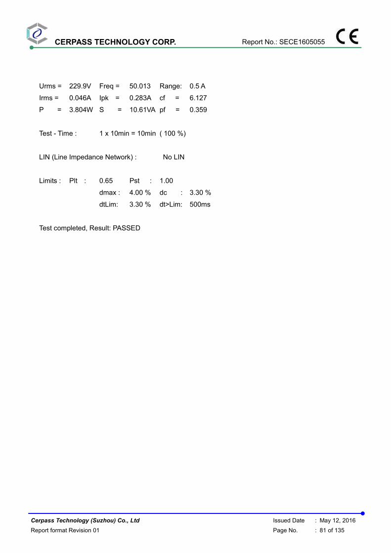
CERPASS TECHNOLOGY CORP. Report No.: SECE1605055
Cerpass Technology (Suzhou) Co., Ltd Issued Date : May 12, 2016
Report format Revision 01 Page No. : 81 of 135
Urms = 229.9V Freq = 50.013 Range: 0.5 A
Irms = 0.046A Ipk = 0.283A cf = 6.127
P = 3.804W S = 10.61VA pf = 0.359
Test - Time : 1 x 10min = 10min ( 100 %)
LIN (Line Impedance Network) : No LIN
Limits : Plt : 0.65 Pst : 1.00
dmax : 4.00 % dc : 3.30 %
dtLim: 3.30 % dt>Lim: 500ms
Test completed, Result: PASSED
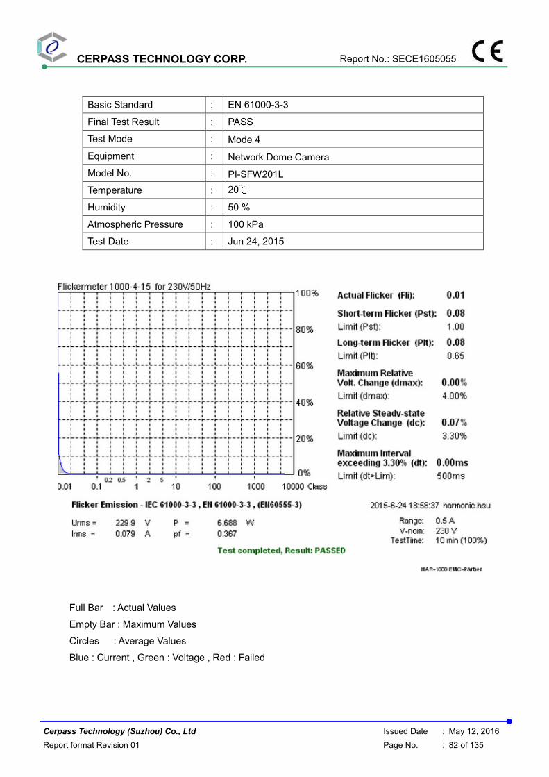
CERPASS TECHNOLOGY CORP. Report No.: SECE1605055
Cerpass Technology (Suzhou) Co., Ltd Issued Date : May 12, 2016
Report format Revision 01 Page No. : 82 of 135
Basic Standard : EN 61000-3-3
Final Test Result : PASS
Test Mode : Mode 4
Equipment : Network Dome Camera
Model No. : PI-SFW201L
Temperature : 20℃
Humidity : 50 %
Atmospheric Pressure : 100 kPa
Test Date : Jun 24, 2015
Full Bar : Actual Values
Empty Bar : Maximum Values
Circles : Average Values
Blue : Current , Green : Voltage , Red : Failed

CERPASS TECHNOLOGY CORP. Report No.: SECE1605055
Cerpass Technology (Suzhou) Co., Ltd Issued Date : May 12, 2016
Report format Revision 01 Page No. : 83 of 135
Urms = 229.9V Freq = 49.987 Range: 0.5 A
Irms = 0.079A Ipk = 0.181A cf = 2.283
P = 6.688W S = 18.24VA pf = 0.367
Test - Time : 1 x 10min = 10min ( 100 %)
LIN (Line Impedance Network) : No LIN
Limits : Plt : 0.65 Pst : 1.00
dmax : 4.00 % dc : 3.30 %
dtLim: 3.30 % dt>Lim: 500ms
Test completed, Result: PASSED
Test engineer:

CERPASS TECHNOLOGY CORP. Report No.: SECE1605055
Cerpass Technology (Suzhou) Co., Ltd Issued Date : May 12, 2016
Report format Revision 01 Page No. : 84 of 135
7.4. Test Photographs

CERPASS TECHNOLOGY CORP. Report No.: SECE1605055
Cerpass Technology (Suzhou) Co., Ltd Issued Date : May 12, 2016
Report format Revision 01 Page No. : 85 of 135
8. Electrostatic Discharge Immunity Test
8.1. Test Procedure
a. In the case of air discharge testing the climatic conditions shall be within the following ranges:
� ambient temperature: 15℃ to 35℃;
� relative humidity : 30% to 60%;
� atmospheric pressure : 86 KPa (860 mbar) to 106 KPa (1060 mbar).
b. Test programs and software shall be chosen so as to exercise all normal modes of operation
of the EUT. The use of special exercising software is encouraged, but permitted only
where it can be shown that the EUT is being comprehensively exercised.
c. The test voltage shall be increased from the minimum to the selected test severity level, in
order to determine any threshold of failure. The final severity level should not exceed the
product specification value in order to avoid damage to the equipment.
d. The test shall be performed with both air discharge and contact discharge. On reselected
points at least 10 single discharges (in the most sensitive polarity) shall be applied on air
discharge. On reselected points at least 25 single discharges (in the most sensitive polarity)
shall be applied on contact discharge.
e. For the time interval between successive single discharges an initial value of one second is
recommended. Longer intervals may be necessary to determine whether a system failure
has occurred.
f. In the case of contact discharges, the tip of the discharge electrode shall touch the EUT
before the discharge switch is operated.
g. In the case of painted surface covering a conducting substrate, the following procedure shall
be adopted :
� If the coating is not declared to be an insulating coating by the equipment manufacturer, then
the pointed tip of the generator shall penetrate the coating so as to make contact with the
conducting substrate.
� Coating declared as insulating by the manufacturer shall only be submitted to the air
discharge.
� The contact discharge test shall not be applied to such surfaces.
h. In the case of air discharges, the round discharge tip of the discharge electrode shall be
approached as fast as possible (without causing mechanical damage) to touch the EUT .
After each discharge, the ESD generator (discharge electrode) shall be removed from the
EUT. The generator is then retriggered for a new single discharge. This procedure shall be
repeated until the discharges are completed. In the case of an air discharge test, the
discharge switch, which is used for contact discharge, shall be closed.

CERPASS TECHNOLOGY CORP. Report No.: SECE1605055
Cerpass Technology (Suzhou) Co., Ltd Issued Date : May 12, 2016
Report format Revision 01 Page No. : 86 of 135
8.2. Test Setup for Tests Performed in Laboratory
The test setup consists of the test generator, EUT and auxiliary instrumentation necessary to
perform DIRECT and INDIRECT application of discharges to the EUT as applicable, in the follow
manner :
a. Contact Discharge to the conductive surfaces and to coupling plane;
b. Air Discharge at insulating surfaces.
The preferred test method is that of type tests performed in laboratories and the only accepted
method of demonstrating conformance with this standard. The EUT was arranged as closely as
possible to arrangement in final installed conditions.
A ground reference plane was provided on the floor of the test site. It was a metallic sheet
(copper or aluminum) of 0.25 mm, minimum thickness; other metallic may be used but they shall
have at least 0.65 mm thickness. In the Cerpass Technology Corp., we provided 1 mm thickness
stainless steel ground reference plane. The minimum size of the ground reference plane is 2.5 m
x 2.5 m, the exact size depending on the dimensions of the EUT. It was connected to the
protective grounding system.
The EUT was arranged and connected according to its functional requirements. A distance of 1m
minimum was provided between the EUT and the wall of the lab. and any other metallic structure.
In cases where this length exceeds the length necessary to apply the discharges to the selected
points, the excess length shall, where possible, be placed non-inductively off the ground
reference plane and shall not come closer than 0.2m to other conductive parts in the test setup.
Where the EUT is installed on a metal table, the table was connected to the reference plane via a
cable with a 470k ohm resister located at each end, to prevent a build-up of charge. The test
setup was consist a wooden table, 0.8m high, standing on the ground reference plane. A HCP,
1.6 m x 0.8 m, was placed on the table. The EUT and cables was isolated from the HCP by an
insulating support 0.5 mm thick. The VCP size, 0.5 m x 0.5 m.
HCP
Table Size
1.6LX0.8WX0.8H m
VCP: 0.5x0.5 m
470K ohm
GRP
470K ohm
470K ohm
470K ohm
10cm10cm
EUT
1.6mx0.8m

CERPASS TECHNOLOGY CORP. Report No.: SECE1605055
Cerpass Technology (Suzhou) Co., Ltd Issued Date : May 12, 2016
Report format Revision 01 Page No. : 87 of 135
8.3. Test Severity Levels
Contact Discharge Air Discharge
Level Test Voltage (KV) of
Contact discharge
Level Test Voltage (KV) of
Air Discharge
1 ±2 1 ±2
2 ±4 2 ±4
3 ±6 3 ±8
4 ±8 4 ±15
X Specified X Specified
Remark: “X” is an open level.
8.4. Measurement Equipment
Instrument/Ancillary Manufacturer Model No. Serial No. Calibration
Date Valid Date.
ESD Simulator EM Test dito V0714102399 2015.03.29 2016.03.28
Tonometer shanghaifengyun DYM3 3251 2014.12.01 2015.11.30
Dehumidifier ZEDO ZD-220LB CEP-TH-01 N/A N/A
Humidifier YADU YZ-DS251C CEP-TH-02 N/A N/A
Temperature/
Humidity Meter feiyan N/A 102 2015.04.02 2016.04.01

CERPASS TECHNOLOGY CORP. Report No.: SECE1605055
Cerpass Technology (Suzhou) Co., Ltd Issued Date : May 12, 2016
Report format Revision 01 Page No. : 88 of 135
8.5. Test Result and Data
Basic Standard : IEC 61000-4-2
Product Standard : EN 50130-4: 2011
Product Standard : EN 55024 : 2010
Equipment : Network Dome Camera
Model No. : PI-SFW401L, PI-SFW201L
Final Test Result : PASS
Temperature : 16°C
Relative Humidity : 50 %
Atmospheric Pressure : 100 kPa
Test Date : Jun 18, 2015
For EN 55024: 2010
Mode 1& Mode 2
Test Voltage: AC 230V/50Hz
Contact Discharge Air Discharge
25 times / each 10 times / each
Voltage 2 kV 4 kV 6 kV 8 kV 2 kV 4 kV 8 kV 10 kV Point\Polarity + - + - + - + - + - + - + - + -
HCP A A A A --- --- --- --- --- --- --- --- --- --- --- --- VCP A A A A --- --- --- --- --- --- --- --- --- --- --- ---
1-17 A A A A --- --- --- --- --- --- --- --- --- --- --- ---
18-22 --- --- --- --- --- --- --- --- A A A A A A --- ---
23-29 A A A A --- --- --- --- --- --- --- --- --- --- --- ---
30,31 --- --- --- --- --- --- --- --- A A A A A A --- ---
Mode 3& Mode 4
Test Voltage: AC 230V/50Hz
Contact Discharge Air Discharge
25 times / each 10 times / each
Voltage 2 kV 4 kV 6 kV 8 kV 2 kV 4 kV 8 kV 10 kV Point\Polarity + - + - + - + - + - + - + - + -
HCP A A A A --- --- --- --- --- --- --- --- --- --- --- --- VCP A A A A --- --- --- --- --- --- --- --- --- --- --- ---
1-25 A A A A --- --- --- --- --- --- --- --- --- --- --- ---
26-32 --- --- --- --- --- --- --- --- A A A A A A --- ---

CERPASS TECHNOLOGY CORP. Report No.: SECE1605055
Cerpass Technology (Suzhou) Co., Ltd Issued Date : May 12, 2016
Report format Revision 01 Page No. : 89 of 135
For EN 50130-4: 2011
Mode 1& Mode 2
Test Voltage: AC 230V/50Hz
Contact Discharge Air Discharge
25 times / each 10 times / each
Voltage 2 kV 4 kV 6 kV 8 kV 2 kV 4 kV 8 kV 10 kV Point\Polarity + - + - + - + - + - + - + - + -
HCP A A A A A A --- --- --- --- --- --- --- --- --- --- VCP A A A A A A --- --- --- --- --- --- --- --- --- ---
1-17 A A A A A A --- --- --- --- --- --- --- --- --- ---
18-22 --- --- --- --- --- --- --- --- A A A A A A --- ---
23-29 A A A A A A --- --- --- --- --- --- --- --- --- ---
30,31 --- --- --- --- --- --- --- --- A A A A A A --- ---
Test Voltage: AC 195.5V/50Hz
Contact Discharge Air Discharge
25 times / each 10 times / each
Voltage 2 kV 4 kV 6 kV 8 kV 2 kV 4 kV 8 kV 10 kV Point\Polarity + - + - + - + - + - + - + - + -
HCP A A A A A A --- --- --- --- --- --- --- --- --- --- VCP A A A A A A --- --- --- --- --- --- --- --- --- ---
1-17 A A A A A A --- --- --- --- --- --- --- --- --- ---
18-22 --- --- --- --- --- --- --- --- A A A A A A --- ---
23-29 A A A A A A --- --- --- --- --- --- --- --- --- ---
30,31 --- --- --- --- --- --- --- --- A A A A A A --- ---
Test Voltage: AC 253V/50Hz
Contact Discharge Air Discharge
25 times / each 10 times / each
Voltage 2 kV 4 kV 6 kV 8 kV 2 kV 4 kV 8 kV 10 kV Point\Polarity + - + - + - + - + - + - + - + -
HCP A A A A A A --- --- --- --- --- --- --- --- --- --- VCP A A A A A A --- --- --- --- --- --- --- --- --- ---
1-17 A A A A A A --- --- --- --- --- --- --- --- --- ---
18-22 --- --- --- --- --- --- --- --- A A A A A A --- ---
23-29 A A A A A A --- --- --- --- --- --- --- --- --- ---
30,31 --- --- --- --- --- --- --- --- A A A A A A --- ---

CERPASS TECHNOLOGY CORP. Report No.: SECE1605055
Cerpass Technology (Suzhou) Co., Ltd Issued Date : May 12, 2016
Report format Revision 01 Page No. : 90 of 135
Mode 3 & Mode 4
Test Voltage: AC 230V/50Hz
Contact Discharge Air Discharge
25 times / each 10 times / each
Voltage 2 kV 4 kV 6 kV 8 kV 2 kV 4 kV 8 kV 10 kV Point\Polarity + - + - + - + - + - + - + - + -
HCP A A A A A A --- --- --- --- --- --- --- --- --- --- VCP A A A A A A --- --- --- --- --- --- --- --- --- ---
1-25 A A A A A A --- --- --- --- --- --- --- --- --- ---
26-32 --- --- --- --- --- --- --- --- A A A A A A --- ---
Test Voltage: AC 195.5V/50Hz
Contact Discharge Air Discharge
25 times / each 10 times / each
Voltage 2 kV 4 kV 6 kV 8 kV 2 kV 4 kV 8 kV 10 kV Point\Polarity + - + - + - + - + - + - + - + -
HCP A A A A A A --- --- --- --- --- --- --- --- --- --- VCP A A A A A A --- --- --- --- --- --- --- --- --- ---
1-25 A A A A A A --- --- --- --- --- --- --- --- --- ---
26-32 --- --- --- --- --- --- --- --- A A A A A A --- ---
Test Voltage: AC 253V/50Hz
Contact Discharge Air Discharge
25 times / each 10 times / each
Voltage 2 kV 4 kV 6 kV 8 kV 2 kV 4 kV 8 kV 10 kV Point\Polarity + - + - + - + - + - + - + - + -
HCP A A A A A A --- --- --- --- --- --- --- --- --- --- VCP A A A A A A --- --- --- --- --- --- --- --- --- ---
1-25 A A A A A A --- --- --- --- --- --- --- --- --- ---
26-32 --- --- --- --- --- --- --- --- A A A A A A --- ---
Test engineer:

CERPASS TECHNOLOGY CORP. Report No.: SECE1605055
Cerpass Technology (Suzhou) Co., Ltd Issued Date : May 12, 2016
Report format Revision 01 Page No. : 91 of 135
8.6. Test Photographs

CERPASS TECHNOLOGY CORP. Report No.: SECE1605055
Cerpass Technology (Suzhou) Co., Ltd Issued Date : May 12, 2016
Report format Revision 01 Page No. : 92 of 135
Mode 1 & Mode 2
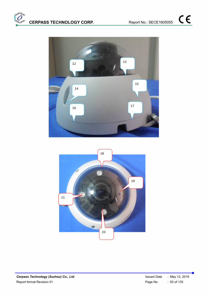
CERPASS TECHNOLOGY CORP. Report No.: SECE1605055
Cerpass Technology (Suzhou) Co., Ltd Issued Date : May 12, 2016
Report format Revision 01 Page No. : 93 of 135

CERPASS TECHNOLOGY CORP. Report No.: SECE1605055
Cerpass Technology (Suzhou) Co., Ltd Issued Date : May 12, 2016
Report format Revision 01 Page No. : 94 of 135

CERPASS TECHNOLOGY CORP. Report No.: SECE1605055
Cerpass Technology (Suzhou) Co., Ltd Issued Date : May 12, 2016
Report format Revision 01 Page No. : 95 of 135
Mode 3 & Mode 4

CERPASS TECHNOLOGY CORP. Report No.: SECE1605055
Cerpass Technology (Suzhou) Co., Ltd Issued Date : May 12, 2016
Report format Revision 01 Page No. : 96 of 135

CERPASS TECHNOLOGY CORP. Report No.: SECE1605055
Cerpass Technology (Suzhou) Co., Ltd Issued Date : May 12, 2016
Report format Revision 01 Page No. : 97 of 135

CERPASS TECHNOLOGY CORP. Report No.: SECE1605055
Cerpass Technology (Suzhou) Co., Ltd Issued Date : May 12, 2016
Report format Revision 01 Page No. : 98 of 135
9. Radio Frequency electromagnetic field immunity test
9.1. Test Procedure
a. The equipment to be tested is placed in the center of the enclosure on a wooden table. The
equipment is then connected to power and signal leads according to pertinent installation
instructions.
b. The antenna which is enabling the complete frequency range of 80-1000 MHz is placed 3m
away from the equipment. The required field strength is determined by placing the field
strength meter(s) on top of or directly alongside the equipment under test and monitoring the
field strength meter via a remote field strength indicator outside the enclosure while adjusting
the continuous-wave to the applicable antennae.
c. The test is normally performed with the antenna facing the most sensitive side of the EUT. The
polarization of the field generated by the bucolical antenna necessitates testing each position
twice, once with the antenna positioned vertically and again with the antenna positioned
horizontally. The circular polarization of the field from the log-spiral antenna makes a change
of position of the antenna unnecessary.
d. At each of the above conditions, the frequency range is swept 80-1000 MHz, pausing to adjust
the R.F. signal level or to switch oscillators and antenna. The rate of sweep is in the order of
1.5*10-3 decades/s. The sensitive frequencies or frequencies of dominant interest may be
discretely analyzed.
9.2. Test Severity Levels
Frequency Band : 80-1000 MHz
Level Test field strength (V/m)
1 1
2 3
3 10
X Specified
Remark: “X” is an open class.

CERPASS TECHNOLOGY CORP. Report No.: SECE1605055
Cerpass Technology (Suzhou) Co., Ltd Issued Date : May 12, 2016
Report format Revision 01 Page No. : 99 of 135
9.3. TEST SETUP
� For the actual test configuration, please refer to the related item – Photographs of the Test
Configuration.
NOTE:
TABLETOP EQUIPMENT
The EUT installed in a representative system as described in section 7 of IEC 61000-4-3 was placed on a non-conductive table 0.8 meters in height. The system under test was connected to the power and signal wire according to relevant installation instructions.
FLOOR STANDING EQUIPMENT
The EUT installed in a representative system as described in section 7 of IEC 61000-4-3 was placed on a non-conductive wood support 0.1 meters in height. The system under test was connected to the power and signal wire according to relevant installation instructions.

CERPASS TECHNOLOGY CORP. Report No.: SECE1605055
Cerpass Technology (Suzhou) Co., Ltd Issued Date : May 12, 2016
Report format Revision 01 Page No. : 100 of 135
9.4. Measurement Equipment
Instrument/Ancillary Manufacturer Model No. Serial No. Calibration
Date Valid Date.
Signal Generator R&S SML03 103287 2015.03.29 2016.03.28
Power Sensor R&S NR P-Z91 100383 2015.03.29 2016.03.28
Power Sensor R&S NRP-Z91 100384 2015.03.29 2016.03.28
Power Meter R&S NRP 101206 2015.03.29 2016.03.28
Power Amplifer BONN BLWA0830-16
0/100/40D 076659 2015.03.29 2016.03.28
Istropic Electric Field
Probe
EST.LINDGRE
N HI-6105 137445 2014.09.01 2015.09.01
EMS Antenna R&S HL046E 100028 N/A N/A
Temperature/
Humidity Meter feiyan N/A 101 2015.04.02 2016.04.01
EMC-32 Rohde&Schwa
rz Ver 6.10.0 N/A N/A N/A

CERPASS TECHNOLOGY CORP. Report No.: SECE1605055
Cerpass Technology (Suzhou) Co., Ltd Issued Date : May 12, 2016
Report format Revision 01 Page No. : 101 of 135
9.5. Test Result and Data
Basic Standard : IEC 61000-4-3
Product Standard : EN 50130-4: 2011
Product Standard : EN 55024 : 2010
Equipment : Network Dome Camera
Model No. : PI-SFW401L, PI-SFW201L
Final Test Result : PASS
Temperature : 17°C
Relative Humidity : 50%
Atmospheric Pressure : 100 kPa
Test Date : Jun 19, 2015
Mode 1& Mode 2& Mode 3& Mode 4
For EN 55024: 2010
Modulation : AM 80% , 1KHz sine wave , Dwell time: 3.0 S
Frequency Step Size : 1 % of preceding frequency value
Frequency (MHz) Antenna Polarization face Field strength (V/m) Result
80~1000 Horizontal &Vertical Front 3 V/m A
80~1000 Horizontal &Vertical Rear 3 V/m A
80~1000 Horizontal &Vertical Left 3 V/m A
80~1000 Horizontal &Vertical Right 3 V/m A
Mode 1& Mode 2& Mode 3& Mode 4
For EN 50130-4: 2011
Test Voltage: AC 230V/50Hz
Modulation : AM 80% , 1KHz sine wave , Dwell time: 3.0S
Frequency Step Size : 1 % of preceding frequency value
Frequency (MHz) Antenna Polarization face Field strength (V/m) Result
80~2700 Horizontal &Vertical Front 10 V/m A
80~2700 Horizontal &Vertical Rear 10 V/m A
80~2700 Horizontal &Vertical Left 10 V/m A
80~2700 Horizontal &Vertical Right 10 V/m A
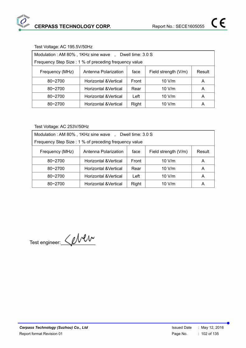
CERPASS TECHNOLOGY CORP. Report No.: SECE1605055
Cerpass Technology (Suzhou) Co., Ltd Issued Date : May 12, 2016
Report format Revision 01 Page No. : 102 of 135
Test Voltage: AC 195.5V/50Hz
Modulation : AM 80% , 1KHz sine wave , Dwell time: 3.0 S
Frequency Step Size : 1 % of preceding frequency value
Frequency (MHz) Antenna Polarization face Field strength (V/m) Result
80~2700 Horizontal &Vertical Front 10 V/m A
80~2700 Horizontal &Vertical Rear 10 V/m A
80~2700 Horizontal &Vertical Left 10 V/m A
80~2700 Horizontal &Vertical Right 10 V/m A
Test Voltage: AC 253V/50Hz
Modulation : AM 80% , 1KHz sine wave , Dwell time: 3.0 S
Frequency Step Size : 1 % of preceding frequency value
Frequency (MHz) Antenna Polarization face Field strength (V/m) Result
80~2700 Horizontal &Vertical Front 10 V/m A
80~2700 Horizontal &Vertical Rear 10 V/m A
80~2700 Horizontal &Vertical Left 10 V/m A
80~2700 Horizontal &Vertical Right 10 V/m A
Test engineer:

CERPASS TECHNOLOGY CORP. Report No.: SECE1605055
Cerpass Technology (Suzhou) Co., Ltd Issued Date : May 12, 2016
Report format Revision 01 Page No. : 103 of 135
9.6. Test Photographs

CERPASS TECHNOLOGY CORP. Report No.: SECE1605055
Cerpass Technology (Suzhou) Co., Ltd Issued Date : May 12, 2016
Report format Revision 01 Page No. : 104 of 135
10. Electrical Fast Transient/ Burst Immunity Test
10.1. Test Procedure
a. In order to minimize the effect of environmental parameters on test results, the climatic conditions when test is carrying out shall comply with the following requirements: � ambient temperature: 15℃ to 35℃; � relative humidity : 45% to 75%; � Atmospheric pressure: 86 Kpa (860 mbar) to 106 Kpa (1060 mbar).
b. In order to minimize the effect of environmental parameters on test results, the electromagnetic environment of the laboratory shall not influence the test results.
c. The variety and diversity of equipment and systems to be tested make it difficult to establish general criteria for the evaluation of the effects of fast transients/bursts on equipment and systems.
d. Test on Power Line: � The EFT/B-generator was located on the GRP.
For floor standing equipment 1,0 m For table top equipment 0,5 m
� The EFT/B-generator provides the ability to apply the test voltage in a non-symmetrical condition to the power supply input terminals of the EUT.
e. Test on Communication Lines � The coupling clamp is composed of a clamp unit for housing the cable (length more than 3
m), and was placed on the GRP. � The coupling clamp provides the ability of coupling the fast transient/bursts to the cable
under test. f. The test results may be classified on the basic of the operating conditions and the functional
specification of the equipment under test, according to the following performance criteria : � Normal performance within the specification limits. � Temporary degradation or loss of function or performance which is self-recoverable. � Temporary degradation or loss of function or performance which requires operator
intervention or system reset. � Degradation or loss of function which is not recoverable due to damage of equipment
(components).
10.2. Test Severity Levels
The following test severity levels are recommended for the fast transient/burst test :
Open circuit output test voltage ± 10%
Level On Power Supply On I/O signal, data and control line
1 0.5 KV 0.25 KV
2 1.0 KV 0.50 KV
3 2.0 KV 1.00 KV
4 4.0 KV 2.00 KV
X Specified Specified
Remark : “ X ” is an open level. The level is subject to negotiation between the user and
manufacturer or is specified by the manufacturer.

CERPASS TECHNOLOGY CORP. Report No.: SECE1605055
Cerpass Technology (Suzhou) Co., Ltd Issued Date : May 12, 2016
Report format Revision 01 Page No. : 105 of 135
10.3. TEST SETUP
� For the actual test configuration, please refer to the related item – Photographs of the
Test Configuration.
NOTE:
TABLETOP EQUIPMENT
The configuration consisted of a wooden table (0.1m high) standing on the Ground Reference Plane. The GRP consisted of a sheet of aluminum (at least 0.25mm thick and 2.5m square) connected to the protective grounding system. A minimum distance of 0.5m was provided between the EUT and the walls of the laboratory or any other metallic structure.
FLOOR STANDING EQUIPMENT
The EUT installed in a representative system as described in section 7 of IEC 61000-4-4 and its cables, were isolated from the Ground Reference Plane by an insulating support that is 0.1-meter thick. The GRP consisted of a sheet of aluminum (at least 0.25mm thick and 2.5m square) connected to the protective grounding system.
0.1m Controller Computer
EFT/Burst Generator
EUT Support
AC Line
GRP
This length should be 0.5m + 0.05m
Injection Clamp EFT/Burst Generator
To Load
AC Line
0.1m
This length between clamp and EUT should be 0.5m ± 0.05m
GRP
Support Units EUT

CERPASS TECHNOLOGY CORP. Report No.: SECE1605055
Cerpass Technology (Suzhou) Co., Ltd Issued Date : May 12, 2016
Report format Revision 01 Page No. : 106 of 135
10.4. Measurement Equipment
Instrument/Ancillary Manufacturer Model No. Serial No. Calibration
Date Valid Date.
TRANSIENT EMCPARTNER TRA2000IN6 901 2015.03.29 2016.03.28
CDN EMCPARTNER CDN2000-06-32 121 2015.03.29 2016.03.28
Coupling clamp EMCPARTNER CN-EFT1000 547 2015.03.29 2016.03.28
Temperature/ Humidity Meter Zhicheng ZC1-11 CEP-TH-005 2015.04.02 2016.04.01

CERPASS TECHNOLOGY CORP. Report No.: SECE1605055
Cerpass Technology (Suzhou) Co., Ltd Issued Date : May 12, 2016
Report format Revision 01 Page No. : 107 of 135
10.5. Test Result and Data
Basic Standard : IEC 61000-4-4
Product Standard : EN 50130-4: 2011
Product Standard : EN 55024 : 2010
Equipment : Network Dome Camera
Model No. : PI-SFW401L, PI-SFW201L
Final Test Result : PASS
Temperature : 18°C
Relative Humidity : 49 %
Atmospheric Pressure : 100 kPa
Test Date : Jun 20, 2015
Mode 1& Mode 2& Mode 3& Mode 4
For EN 55024: 2010
Pulse : 5/50 ns
Repetition Rate: 5 kHz Burst : 15m/300ms
Test time : 1 min/each condition
Voltage/ Mode/ Polarity/ Result/ Phase 0.5 kV 1.0 kV
+ - + -
Power Line
L --- --- A A
N --- --- A A
L-N --- --- A A
Signal Line
RJ45(10Mbps+POE)
A A --- ---
RJ45(100Mbps+POE)
A A --- ---

CERPASS TECHNOLOGY CORP. Report No.: SECE1605055
Cerpass Technology (Suzhou) Co., Ltd Issued Date : May 12, 2016
Report format Revision 01 Page No. : 108 of 135
Mode 1& Mode 2& Mode 3& Mode 4
For EN 50130-4: 2011 Test Voltage: AC 230V/50Hz
Pulse : 5/50 ns
Repetition Rate: 5/100 kHz Burst : 15m/300ms
Test time : 1 min/each condition
Voltage/ Mode/ Polarity/ Result/ Phase 1.0 kV 2.0 kV
+ - + -
Power Line
L --- --- A A
N --- --- A A
L-N --- --- A A
Signal Line
RJ45(10Mbps+POE)
A A --- ---
RJ45(100Mbps+POE)
A A --- ---
Test Voltage: AC 195.5V/50Hz
Pulse : 5/50 ns
Repetition Rate: 5/100 kHz Burst : 15m/300ms
Test time : 1 min/each condition
Voltage/ Mode/ Polarity/ Result/ Phase 1.0 kV 2.0 kV
+ - + -
Power Line
L --- --- A A
N --- --- A A
L-N --- --- A A
Signal Line
RJ45(10Mbps+POE)
A A --- ---
RJ45(100Mbps+POE)
A A --- ---
Test Voltage: AC 253V/50Hz
Pulse : 5/50 ns
Repetition Rate: 5/100 kHz Burst : 15m/300ms
Test time : 1 min/each condition
Voltage/ Mode/ Polarity/ Result/ Phase 1.0 kV 2.0 kV
+ - + -
Power Line
L --- --- A A
N --- --- A A
L-N --- --- A A
Signal Line
RJ45(10Mbps+POE)
A A --- ---
RJ45(100Mbps+POE)
A A --- ---
Test engineer:

CERPASS TECHNOLOGY CORP. Report No.: SECE1605055
Cerpass Technology (Suzhou) Co., Ltd Issued Date : May 12, 2016
Report format Revision 01 Page No. : 109 of 135
10.6. Test Photographs
Main

CERPASS TECHNOLOGY CORP. Report No.: SECE1605055
Cerpass Technology (Suzhou) Co., Ltd Issued Date : May 12, 2016
Report format Revision 01 Page No. : 110 of 135
LAN

CERPASS TECHNOLOGY CORP. Report No.: SECE1605055
Cerpass Technology (Suzhou) Co., Ltd Issued Date : May 12, 2016
Report format Revision 01 Page No. : 111 of 135
11. Surge Immunity Test
11.1. Test Procedure
a. Climatic conditions The climatic conditions shall comply with the following requirements : � ambient temperature : 15 to 35 ℃ ℃ � relative humidity : 10 % to 75 % � atmospheric pressure : 86 kPa to 106 kPa ( 860 mbar to 1060 mbar )
b. Electromagnetic conditions the electromagnetic environment of the laboratory shall not influence the test results.
c. The test shall be performed according the test plan that shall specify the test set-up with � generator and other equipment utilized; � test level ( voltage/current ); � generator source impedance; � internal or external generator trigger; � number of tests : at least five positive and five negative at the selected points; � repetition rate : maximum 1/min. � inputs and outputs to be tested; � representative operating conditions of the EUT; � sequence of application of the surge to the circuit; � phase angle in the case of AC. power supply; � actual installation conditions, for example :
AC : neutral earthed, DC : ( + ) or ( - ) earthed to simulated the actual earthing conditions.
d. If not otherwise specified the surges have to be applied synchronized to the voltage phase at the zero-crossing and the peak value of the AC. voltage wave ( positive and negative ).
e. The surges have to be applied line to line and line(s) and earth. When testing line to earth, the test voltage has to be applied successively between each of the lines and earth, if there is no other specification.
f. The test procedure shall also consider the non-linear current-voltage characteristics of the equipment under test. Therefore the test voltage has to be increased by steps up to the test level specified in the product standard or test plan.
g. All lower levels including the selected test level shall be satisfied. For testing the secondary protection, the output voltage of the generator shall be increased up to the worst-case voltage breakdown level ( let-through level ) of the primary protection.
h. If the actual operating signal sources are not available, that may be simulated. Under no circumstances may the test level exceed the product specification. The test shall be carried out according to a test plan.
i. To find all critical points of the duty cycle of the equipment, a sufficient number of positive and negative test pulses shall be applied. For acceptance test previously unstressed equipment shall be used to the protection devices shall be replaced.
11.2. Test Severity Level
Level Open-circuit test voltage, ± 10%, KV
1 0.5
2 1.0
3 2.0
4 4.0
X Specified
NOTE: “X” is an open class. This level can be specified in the product specification.
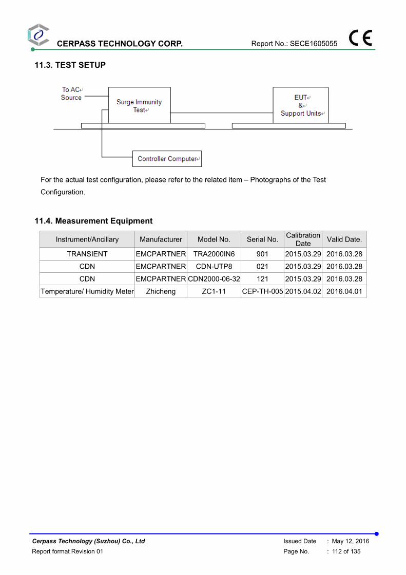
CERPASS TECHNOLOGY CORP. Report No.: SECE1605055
Cerpass Technology (Suzhou) Co., Ltd Issued Date : May 12, 2016
Report format Revision 01 Page No. : 112 of 135
11.3. TEST SETUP
For the actual test configuration, please refer to the related item – Photographs of the Test
Configuration.
11.4. Measurement Equipment
Instrument/Ancillary Manufacturer Model No. Serial No. Calibration
Date Valid Date.
TRANSIENT EMCPARTNER TRA2000IN6 901 2015.03.29 2016.03.28
CDN EMCPARTNER CDN-UTP8 021 2015.03.29 2016.03.28
CDN EMCPARTNER CDN2000-06-32 121 2015.03.29 2016.03.28
Temperature/ Humidity Meter Zhicheng ZC1-11 CEP-TH-005 2015.04.02 2016.04.01

CERPASS TECHNOLOGY CORP. Report No.: SECE1605055
Cerpass Technology (Suzhou) Co., Ltd Issued Date : May 12, 2016
Report format Revision 01 Page No. : 113 of 135
11.5. Test Result and Data
Basic Standard : IEC 61000-4-5
Product Standard : EN 50130-4: 2011
Product Standard : EN 55024 : 2010
Equipment : Network Dome Camera
Model No. : PI-SFW401L, PI-SFW201L
Final Test Result : PASS
Temperature : 18°C
Relative Humidity : 49 %
Atmospheric Pressure : 100 kPa
Test Date : Jun 20, 2015
Mode 1& Mode 2& Mode 3& Mode 4
For EN 55024: 2010
Waveform : 1.2/50µs(8/20µs) Repetition rate : 60 sec Time : 20 time/each condition
/Phase Voltage / Mode / Polarity / Result 0° 90° 180° 270°
0.5/1.0 kV L-N + A A A A - A A A A
Waveform :10/700µs Repetition rate : 60 sec Time : 5 time/each condition
Voltage 0.5 kV 1 kV
Mode / Polarity / Result + - + -
RJ45(10Mbps+POE) A A A A
RJ45(100Mbps+POE) A A A A

CERPASS TECHNOLOGY CORP. Report No.: SECE1605055
Cerpass Technology (Suzhou) Co., Ltd Issued Date : May 12, 2016
Report format Revision 01 Page No. : 114 of 135
Mode 1& Mode 2& Mode 3& Mode 4
For EN 50130-4: 2011
Test Voltage: AC 230V/50Hz
Waveform : 1.2/50µs(8/20µs) Repetition rate : 60 sec Time : 20 time/each condition
/Phase Voltage / Mode / Polarity / Result 0° 90° 180° 270°
0.5/1.0 kV L-N + A A A A - A A A A
Waveform : 1.2/50µs(8/20µs) Repetition rate : 60 sec Time : 5 time/each condition
Voltage 0.5 kV 1 kV
Mode / Polarity / Result + - + -
RJ45(10Mbps+POE) A A A A
RJ45(100Mbps+POE) A A A A
Waveform : 10/700µs Repetition rate : 60 sec Time : 5 time/each condition
Voltage 0.5 kV 1 kV
Mode / Polarity / Result + - + -
RJ45(10Mbps+POE) A A A A
RJ45(100Mbps+POE) A A A A
Test Voltage: AC 195.5V/50Hz
Waveform : 1.2/50µs(8/20µs) Repetition rate : 60 sec Time : 20 time/each condition
/Phase Voltage / Mode / Polarity / Result 0° 90° 180° 270°
0.5/1.0 kV L-N + A A A A - A A A A

CERPASS TECHNOLOGY CORP. Report No.: SECE1605055
Cerpass Technology (Suzhou) Co., Ltd Issued Date : May 12, 2016
Report format Revision 01 Page No. : 115 of 135
Waveform : 1.2/50µs(8/20µs) Repetition rate : 60 sec Time : 5 time/each condition
Voltage 0.5 kV 1 kV
Mode / Polarity / Result + - + -
RJ45(10Mbps+POE) A A A A
RJ45(100Mbps+POE) A A A A
Waveform : 10/700µs Repetition rate : 60 sec Time : 5 time/each condition
Voltage 0.5 kV 1 kV
Mode / Polarity / Result + - + -
RJ45(10Mbps+POE) A A A A
RJ45(100Mbps+POE) A A A A
Test Voltage: AC 253V/50Hz
Waveform : 1.2/50µs(8/20µs) Repetition rate : 60 sec Time : 20 time/each condition
/Phase Voltage / Mode / Polarity / Result 0° 90° 180° 270°
0.5/1.0 kV L-N + A A A A - A A A A
Waveform : 1.2/50µs(8/20µs) Repetition rate : 60 sec Time : 5 time/each condition
Voltage 0.5 kV 1 kV
Mode / Polarity / Result + - + -
RJ45(10Mbps+POE) A A A A
RJ45(100Mbps+POE) A A A A

CERPASS TECHNOLOGY CORP. Report No.: SECE1605055
Cerpass Technology (Suzhou) Co., Ltd Issued Date : May 12, 2016
Report format Revision 01 Page No. : 116 of 135
Waveform : 10/700µs Repetition rate : 60 sec Time : 5 time/each condition
Voltage 0.5 kV 1 kV
Mode / Polarity / Result + - + -
RJ45(10Mbps+POE) A A A A
RJ45(100Mbps+POE) A A A A
Test engineer:

CERPASS TECHNOLOGY CORP. Report No.: SECE1605055
Cerpass Technology (Suzhou) Co., Ltd Issued Date : May 12, 2016
Report format Revision 01 Page No. : 117 of 135
11.6. Test Photographs
Main

CERPASS TECHNOLOGY CORP. Report No.: SECE1605055
Cerpass Technology (Suzhou) Co., Ltd Issued Date : May 12, 2016
Report format Revision 01 Page No. : 118 of 135
12. Conduction Disturbances induced by Radio-Frequency Fields
12.1. Test Procedure
a. The EUT shall be operated within its intended climatic conditions. The temperature and relative humidity should be recorded.
b. This test method test can be performed without using a sell shielded enclosure. This is because the disturbance levels applied and the geometry of the setups are not likely to radiated a high amount of energy, especially at the lower frequencies. If under certain circumstances the radiated energy is too high, a shielded enclosure has to be used.
c. The test shall be performed with the test generator connected to each of the coupling and decoupling devices in turn while the other non-excited RF-input ports of the coupling devices are terminated by a 50 ohm load resistor.
d. The frequency range is swept from 150 KHz to 80 MHz, using the signal levels established during the setting process, and with the disturbance signal 80% amplitude modulated with a 1KHz sign wave, pausing to adjust the RF-signal level or to switch coupling devices as necessary. The rate of sweep shall no exceed 1.5 x 10
-3 decades/s. Where the frequency is
swept incrementally, the step size shall no exceed 1% of the start and thereafter 1% of the preceding frequency value.
e. The dwell time at each frequency shall not be less than the time necessary for the EUT to be exercised, and able to respond. Sensitive frequencies e.g. clock frequency (ies) and harmonics or frequencies of dominant interest shall be analyzed separately.
f. An alternative test procedure may be adopted, wherein the frequency range is swept incrementally, with a step size not exceeding 4% of the start ad thereafter 4% of the preceding frequency value. The test level should be at least twice the value of the specified test level.
g. In cases of dispute, the test procedure using a step size not exceeding 1% of the start and thereafter 1% of preceding frequency value shall take precedence.
h. Attempts should be made to fully exercise the EUT during testing, and to fully interrogate all exercise modes selected for susceptibility.
i. The use of special exercising programs is recommended. j. Testing shall be performed according to a Test Plan, which shall be included in the test report. k. It may be necessary to carry out some investigatory testing in order to establish some aspects
of the test plan.
12.2. Test Severity Levels
Level Voltage Level ( e.m.f. )
1 1 V
2 3 V
3 10 V
x Specified
NOTE - x is an open class. This level can be specified in the product specification.

CERPASS TECHNOLOGY CORP. Report No.: SECE1605055
Cerpass Technology (Suzhou) Co., Ltd Issued Date : May 12, 2016
Report format Revision 01 Page No. : 119 of 135
12.3. TEST SETUP
Note: 1. The EUT is setup 0.1m above Ground Reference Plane 2. The CDNs and / or EM clamp used for real test depends on ports and cables configuration of
EUT.
3. For the actual test configuration, please refer to the related item – Photographs of the Test
Configuration.
12.4. Measurement Equipment
Instrument/Ancillary Manufacturer Model No. Serial No. Calibration
Date Valid Date.
Conducted immunity
test system FRANKONIA CIT-10/75 102D1294 2015.03.29 2016.03.28
EM Injection clamp FCC F-203I-23MM 536 2015.03.29 2016.03.28
CDN FRANKONIA CDN-T2 A3010029 2015.03.29 2016.03.28
CDN FRANKONIA CDN-T4 A3015017 2015.03.29 2016.03.28
CDN FRANKONIA CDN-T8 A3022010 2015.03.29 2016.03.28
CDN FRANKONIA CDN-M2 A3002037 2015.03.29 2016.03.28
CDN FRANKONIA CDN-M2+M3 A3011102 2015.03.29 2016.03.28
CDN FCC CDN-M5/32 A3013024 2015.03.29 2016.03.28
6 dB Attenuator FRANKONIA N/A N/A 2015.03.29 2016.03.28
Temperature/
Humidity Meter Zhicheng ZC1-11 CEP-TH-005 2015.04.02 2016.04.01
EN61000-4-6 Hubert GmbH Ver 2.21 N/A N/A N/A

CERPASS TECHNOLOGY CORP. Report No.: SECE1605055
Cerpass Technology (Suzhou) Co., Ltd Issued Date : May 12, 2016
Report format Revision 01 Page No. : 120 of 135
12.5. Test Result and Data
Basic Standard : IEC 61000-4-6
Product Standard : EN 50130-4: 2011
Product Standard : EN 55024 : 2010
Equipment : Network Dome Camera
Model No. : PI-SFW401L, PI-SFW201L
Final Test Result : PASS
Temperature : 18°C
Relative Humidity : 49 %
Atmospheric Pressure : 100 kPa
Test Date : Jun 20, 2015
Mode 1& Mode 2& Mode 3& Mode 4
For EN 55024: 2010
Frequency : 0.15~80MHz, Modulation : AM 80%,1KHz sine wave, Dwell time: 3.0s
Frequency Step Size : 1 % of preceding frequency value
Frequency Test mode Voltage(V) Result
0.15 ~ 80MHz Power(M2) 3 A
0.15 ~ 80MHz RJ45(10Mbps+POE) 3 A
0.15 ~ 80MHz RJ45(100Mbps+POE) 3 A
Mode 1& Mode 2& Mode 3& Mode 4
For EN 50130-4: 2011
Test Voltage: AC 230V/50Hz
Frequency : 0.15~100MHz, Modulation : AM 80%,1KHz sine wave, Dwell time: 3.0s
Frequency Step Size : 1 % of preceding frequency value
Frequency Test mode Voltage(V) Result
0.15 ~ 100MHz Power(M2) 10 A
0.15 ~ 100MHz RJ45(10Mbps+POE) 10 A
0.15 ~ 100MHz RJ45(100Mbps+POE) 10 A

CERPASS TECHNOLOGY CORP. Report No.: SECE1605055
Cerpass Technology (Suzhou) Co., Ltd Issued Date : May 12, 2016
Report format Revision 01 Page No. : 121 of 135
Test Voltage: AC 195.5V/50Hz
Frequency : 0.15~100MHz, Modulation : AM 80%,1KHz sine wave, Dwell time: 3.0s
Frequency Step Size : 1 % of preceding frequency value
Frequency Test mode Voltage(V) Result
0.15 ~ 100MHz Power(M2) 10 A
0.15 ~ 100MHz RJ45(10Mbps+POE) 10 A
0.15 ~ 100MHz RJ45(100Mbps+POE) 10 A
Test Voltage: AC 253V/50Hz
Frequency : 0.15~100MHz, Modulation : AM 80%,1KHz sine wave, Dwell time: 3.0s
Frequency Step Size : 1 % of preceding frequency value
Frequency Test mode Voltage(V) Result
0.15 ~ 100MHz Power(M2) 10 A
0.15 ~ 100MHz RJ45(10Mbps+POE) 10 A
0.15 ~ 100MHz RJ45(100Mbps+POE) 10 A
Test engineer:

CERPASS TECHNOLOGY CORP. Report No.: SECE1605055
Cerpass Technology (Suzhou) Co., Ltd Issued Date : May 12, 2016
Report format Revision 01 Page No. : 122 of 135
12.6. Test Photographs

CERPASS TECHNOLOGY CORP. Report No.: SECE1605055
Cerpass Technology (Suzhou) Co., Ltd Issued Date : May 12, 2016
Report format Revision 01 Page No. : 123 of 135
13. Power Frequency Magnetic Field Immunity Test
13.1. Test Setup
GPR : Ground plane C1 : Power supply circuit
A : Safety earth C2 : Signal circuit
S : Insulating support L : Communication line
EUT : Equipment under test B : To power supply source
Lc : Induction coil D : To signal source, simulator
E : Earth terminal G : To the test generator
13.2. Test Severity Levels
Level Magnetic field strength (A/m)
1 1
2 3
3 10
4 30
5 100
X1)
special
NOTE 1 “X” is an open level. This level can be given in the product specification.
13.3. Measurement Equipment
Instrument/Ancillary Manufacturer Model No. Serial No. Calibration
Date Valid Date.
TRANSIENT EMCPARTNER TRA2000IN6 901 2015.03.29 2016.03.28
H-Filed-Loop EMCPARTNER MF1000-1 144 2015.03.29 2016.03.28
Temperature/ Humidity
Meter Zhicheng ZC1-11 CEP-TH-005 2015.04.02 2016.04.01

CERPASS TECHNOLOGY CORP. Report No.: SECE1605055
Cerpass Technology (Suzhou) Co., Ltd Issued Date : May 12, 2016
Report format Revision 01 Page No. : 124 of 135
13.4. Test Result and Data
Basic Standard : IEC 61000-4-8
Product Standard : EN 55024 : 2010
Equipment : Network Dome Camera
Model No. : PI-SFW401L, PI-SFW201L
Final Test Result : PASS
Temperature : 21°C
Relative Humidity : 51%
Atmospheric Pressure : 100 kPa
Test Date : Jun 20,2015
Mode 1& Mode 2& Mode 3& Mode 4
Power Frequency Magnetic Field : 50/60 Hz, 1 A/m
Coil Orientation Testing duration Results
X-axis 1.0 Min A
Y-axis 1.0 Min A
Z-axis 1.0 Min A
Test engineer:

CERPASS TECHNOLOGY CORP. Report No.: SECE1605055
Cerpass Technology (Suzhou) Co., Ltd Issued Date : May 12, 2016
Report format Revision 01 Page No. : 125 of 135
13.5. Test Photographs

CERPASS TECHNOLOGY CORP. Report No.: SECE1605055
Cerpass Technology (Suzhou) Co., Ltd Issued Date : May 12, 2016
Report format Revision 01 Page No. : 126 of 135
14. Voltage Dips and Voltage Interruptions Immunity Test Setup
14.1. Test Conditions
1. Source voltage and frequency : AC 100/230/240V / 50Hz, Single phase.
2. Test of interval : 10 sec.
3. Level and duration : Sequence of 3 dips/interrupts.
4. Voltage rise (and fall) time : 1 ∼ 5 µs.
5. Test severity :
Voltage dips and Interrupt
reduction (%)
Test Duration
(period)
>95% 250
30% 25
>95% 0.5
14.2. TEST SETUP
For the actual test configuration, please refer to the related item – Photographs of the Test
Configuration.
14.3. Measurement Equipment
Instrument/Ancillary Manufacturer Model No. Serial No. Calibration
Date Valid Date.
TRANSIENT EMCPARTNER TRA2000IN6 901 2014.03.24 2015.03.23
Temperature/ Humidity
Meter Zhicheng ZC1-11 CEP-TH-005 2014.03.31 2015.03.30

CERPASS TECHNOLOGY CORP. Report No.: SECE1605055
Cerpass Technology (Suzhou) Co., Ltd Issued Date : May 12, 2016
Report format Revision 01 Page No. : 127 of 135
14.4. Test Result and Data
N/A

CERPASS TECHNOLOGY CORP. Report No.: SECE1605055
Cerpass Technology (Suzhou) Co., Ltd Issued Date : May 12, 2016
Report format Revision 01 Page No. : 128 of 135
15. EUT Photographs
PI-SFW401L
1) EUT Photo
2) EUT Photo

CERPASS TECHNOLOGY CORP. Report No.: SECE1605055
Cerpass Technology (Suzhou) Co., Ltd Issued Date : May 12, 2016
Report format Revision 01 Page No. : 129 of 135
3) EUT Photo
4) EUT Photo

CERPASS TECHNOLOGY CORP. Report No.: SECE1605055
Cerpass Technology (Suzhou) Co., Ltd Issued Date : May 12, 2016
Report format Revision 01 Page No. : 130 of 135
PI-SFW201L
5) EUT Photo
6) EUT Photo

CERPASS TECHNOLOGY CORP. Report No.: SECE1605055
Cerpass Technology (Suzhou) Co., Ltd Issued Date : May 12, 2016
Report format Revision 01 Page No. : 131 of 135
7) EUT Photo
8) EUT Photo

CERPASS TECHNOLOGY CORP. Report No.: SECE1605055
Cerpass Technology (Suzhou) Co., Ltd Issued Date : May 12, 2016
Report format Revision 01 Page No. : 132 of 135
Adapter #1
9) EUT Photo
10) EUT Photo

CERPASS TECHNOLOGY CORP. Report No.: SECE1605055
Cerpass Technology (Suzhou) Co., Ltd Issued Date : May 12, 2016
Report format Revision 01 Page No. : 133 of 135
11) EUT Photo
12) EUT Photo

CERPASS TECHNOLOGY CORP. Report No.: SECE1605055
Cerpass Technology (Suzhou) Co., Ltd Issued Date : May 12, 2016
Report format Revision 01 Page No. : 134 of 135
Adapter #2
13) EUT Photo
14) EUT Photo

CERPASS TECHNOLOGY CORP. Report No.: SECE1605055
Cerpass Technology (Suzhou) Co., Ltd Issued Date : May 12, 2016
Report format Revision 01 Page No. : 135 of 135
15) EUT Photo