Embed Size (px)
Citation preview
EMC® Smarts® Network Protocol Manager Version 9.5
Configuration GuideP/N 302-004-001REV 01

EMC Smarts Network Protocol Manager Configuration Guide2
Copyright © 2004- 2017 Dell Inc. or its subsidiaries. All rights reserved. Published in the USA.
Published September, 2017
Dell believes the information in this publication is accurate as of its publication date. The information is subject to change without notice.
The information in this publication is provided as is. Dell Corporation makes no representations or warranties of any kind with respect to the information in this publication, and specifically disclaims implied warranties of merchantability or fitness for a particular purpose. Use, copying, and distribution of any Dell software described in this publication requires an applicable software license.
Dell, EMC, and other trademarks are registered trademarks or trademarks of Dell Inc. or its subsidiaries in the United States and other countries. All other trademarks used herein are the property of their respective owners.
For the most up-to-date regulatory document for your product line, go to EMC Online Support (https://support.emc.com).
EMC CorporationHopkinton, Massachusetts 01748-91031-508-435-1000 In North America 1-866-464-7381www.EMC.com

CONTENTS
Chapter 1 Introduction
Terminology................................................................................................ 12System and device ................................................................................ 12Modeled topology ................................................................................. 12Object ................................................................................................... 12Network Protocol Manager installation directory.................................... 12
Architectural and functional overview ......................................................... 13IP Availability Manager.......................................................................... 16Network Protocol Manager .................................................................... 16Global Manager..................................................................................... 17Adapter Platform ................................................................................... 17Global Console...................................................................................... 18EMC Smarts Broker................................................................................ 18
Configuration roadmap ............................................................................... 18Network Protocol Manager configuration tasks...................................... 18IP Availability Manager configuration tasks ........................................... 19Global Manager configuration tasks ...................................................... 19Adapter Platform configuration tasks (optional) .................................... 20
What to do after configuration..................................................................... 20
Chapter 2 Setting Configuration Parameters
Domain Manager configuration directories.................................................. 22 User configuration parameters .................................................................... 23 Methods to modify user configuration parameters ...................................... 23
Editing configuration files to modify configuration parameters .............. 23Issuing the dmctl command to modify configuration parameters ........... 25
Description of bgp.conf............................................................................... 27 Description of eigrp.conf............................................................................. 30 Description of isis.conf ............................................................................... 31 Description of ospf.conf.............................................................................. 33 Description of perl-cli.conf .......................................................................... 35 EMC Smarts secure communications........................................................... 36
Chapter 3 Opening the Global Console
Global Console overview............................................................................. 38 User accounts and passwords..................................................................... 38 Procedure for opening the Global Console .................................................. 39 Procedure for opening the Global Manager Administration Console ............ 41 Procedure for opening the Domain Manager Administration Console .......... 41 Procedure for opening the Polling and Thresholds Console ......................... 42
Chapter 4 Configuring IP Availability Manager
Configuration overview ............................................................................... 44 Topology and CLI device-access object import ............................................ 44
Import of topology................................................................................. 45Import of CLI device-access objects....................................................... 45Types of imported objects ..................................................................... 46
EMC Smarts Network Protocol Manager Configuration Guide 3

Contents
About the protocol topology collection sets ................................................ 48 Tagged IP object import .............................................................................. 48
Overlapping IP addresses...................................................................... 49IP tagging feature .................................................................................. 49VPN-Tagging Server ............................................................................... 49
CLI discovery, CLI polling, and CLI device-access groups ............................. 49 Enabling protocol light discovery ................................................................ 51 Enabling overlapping IP address discovery ................................................. 51 Enabling interoperability with the VPN-Tagging Server................................. 52 Creating CLI device-access groups .............................................................. 53
Attach the Polling and Thresholds Console............................................ 53Create CLI device-access groups............................................................ 53Synchronize CLI credentials between IP and NPM.................................. 55
Chapter 5 Configuring the Global Manager
Configuration overview ............................................................................... 58 About the Global Manager .......................................................................... 58 IC Domain Configuration objects ................................................................. 61
IC Domain Configuration creation wizards ............................................. 62IC Domain Configuration server reconfiguration..................................... 63
Loading the XML configuration file for Network Protocol Manager................ 64 Specifying the underlying domains ............................................................. 65
Specify the underlying domains for configuration scenario 1 ................. 66Specify the underlying domains for configuration scenario 2 ................. 70
Enabling the display of BGP, EIGRP, IS-IS, and OSPF topology maps............ 75
Chapter 6 Configuring SNMP Trap Integration
Configuration overview ............................................................................... 78 SNMP trap-integration components ............................................................ 79
Built-in trap receiver.............................................................................. 79SNMP Trap Adapter ............................................................................... 79Adapter Platform ................................................................................... 81
Trap adapter configuration file: trapd.conf .................................................. 81 Configuring the SNMP trap-integration components .................................... 85
Configure the trap exploder................................................................... 85Configure the built-in trap receivers....................................................... 89Configure the trap receiver .................................................................... 90Configure the Adapter Platform ............................................................. 91
Starting the SNMP trap-integration components.......................................... 91Start the trap exploder .......................................................................... 92
Chapter 7 Configuring Syslog Message Processing and Forwarding
Configuration overview ............................................................................... 96 Syslog adapters .......................................................................................... 97 Configuring syslog message processing and forwarding.............................. 97 Configuring syslog message processing...................................................... 98
Chapter 8 Configuring SSH Security
SSH overview............................................................................................ 100SSH1 and SSH2 .................................................................................. 100SSH authentication ............................................................................. 100
CLI modules for Network Protocol Manager ............................................... 102
4 EMC Smarts Network Protocol Manager Configuration Guide

Contents
DASL CLI module................................................................................. 103Perl CLI module ................................................................................... 104
SSH client configuration............................................................................ 105Configuring the SSH client for the DASL CLI module............................. 105Configuring the SSH client for the Perl CLI module ............................... 105
SSH server configuration........................................................................... 106
Chapter 9 Using the Polling and Thresholds Console
Opening the Polling and Thresholds Console ............................................ 112Layout of the Polling and Thresholds Console ..................................... 112Polling and Thresholds Console toolbar buttons.................................. 113
Understanding groups and settings .......................................................... 114 Working with groups and settings ............................................................. 115
Assign managed objects to groups...................................................... 115Modify the properties of a group ......................................................... 115Add or remove settings ....................................................................... 116Modify the parameters of a setting ...................................................... 116Modify the priority of groups ............................................................... 117Edit matching criteria .......................................................................... 117Create new groups .............................................................................. 118
Chapter 10 Configuring Polling and Threshold Groups
Viewing the Polling and Thresholds tabs ................................................... 122 Understanding SNMP polling, CLI polling, and thresholds ......................... 124 Understanding polling groups, threshold groups, and settings.................. 125 Modifying polling and threshold groups.................................................... 125 Default polling groups and settings........................................................... 126
BGP polling group ............................................................................... 127EIGRP polling group............................................................................. 130Cisco Devices polling group ................................................................ 131Juniper Devices polling group.............................................................. 133OSPF polling group.............................................................................. 134
Default threshold groups and settings ...................................................... 137BGP Protocol Endpoints threshold group ............................................. 137
Appendix A Wildcard Patterns
Types of wildcard patterns ........................................................................ 140
Appendix B MIBs Polled and Traps Processed
MIBs polled and traps processed for BGP monitoring ................................ 144MIBs polled by BGP............................................................................. 144Traps processed for BGP ..................................................................... 145
MIBs polled and traps processed for OSPF monitoring .............................. 147MIBs polled by OSPF ........................................................................... 148Traps processed for OSPF.................................................................... 153
MIBs polled for IS-IS monitoring................................................................ 155IS-IS MIB objects that are defined in RFC 1195 .................................... 155IS-IS MIB objects that are defined in RFC 4444 .................................... 157
Appendix C Syslog Messages Processed
Syslog messages processed for BGP monitoring ....................................... 160
EMC Smarts Network Protocol Manager Configuration Guide 5
Contents
Syslog message format ....................................................................... 160Sample syslog message ...................................................................... 160Syslog messages processed and actions taken ................................... 160Enabling BGP Max Route (Prefix) threshold monitoring........................ 161
Syslog messages processed for OSPF monitoring...................................... 162Syslog message format ....................................................................... 162Sample syslog messages .................................................................... 162Syslog messages processed and actions taken ................................... 163
Appendix D CLI Commands for Monitoring
CLI commands for EIGRP monitoring.......................................................... 166 CLI commands for IS-IS monitoring ........................................................... 166 CLI commands for BGP IPv6 discovery and monitoring of Cisco devices..... 167 CLI commands for BGP IPv6 discovery and monitoring of Juniper devices .. 168
Appendix E SNMP Poller
SNMP polling overview ............................................................................. 170 SNMP poller operation .............................................................................. 170
Just-in-time polling.............................................................................. 170Request-consolidation polling............................................................. 171
Appendix F NPM dump instrumentation utility
Network Protocol Manager dump instrumentation utility ........................... 174 Invoking the NPM dump instrumentation utility......................................... 174
BGP instrumentation utility command ................................................. 174EIGRP instrumentation utility command............................................... 174IS-IS instrumentation utility command ................................................ 175OSPF instrumentation utility command................................................ 175
Index
6 EMC Smarts Network Protocol Manager Configuration Guide

Title Page
FIGURES
1 Network Protocol Manager architecture for BGP or OSPF.............................................. 142 Network Protocol Manager architecture for EIGRP or IS-IS ............................................ 153 Domain Manager configuration directories for Network Protocol Manager ................... 224 Preview of how the sm_edit utility works ..................................................................... 245 Attach Manager dialog box.......................................................................................... 396 Topology Browser Console .......................................................................................... 407 Notification Log Console ............................................................................................. 418 Domain Manager Administration Console.................................................................... 429 Importing topology and CLI device-access objects from IP Availability Manager........... 4510 Topology and CLI device-access objects imported from IP Availability Manager ........... 4611 CLI discovery, CLI polling, and CLI device-access object creation and transfer ............. 5012 Global Manager Administration Console interaction with the Global Manager ............. 5913 IC Domain Configuration objects and their relationships ............................................. 6014 Default domain configurations for a Network Protocol Manager deployment................ 6115 Global Manager and Administration Console............................................................... 6216 How reconfiguring the Global Manager works.............................................................. 6317 Access to server tools for loading XML configuration files............................................ 6418 Before and after completing configuration scenario 1.................................................. 6619 Before and after completing configuration scenario 2.................................................. 7020 Using the Domain Creation Wizard to create the EAST-INCHARGE-BGP domain ............ 7221 Using the Domain Creation Wizard to create the EAST-INCHARGE-AM domain.............. 7322 Global Manager Administration Console with admin-profile selected .......................... 7523 Console Operations dialog box.................................................................................... 7624 Recommended trap-integration design........................................................................ 7825 Configuration directory for a trap exploder................................................................... 8126 Mapping of trap exploder configuration steps to configured forwarded-trap paths....... 8627 Recommended syslog message processing and forwarding design ............................. 9628 SSH connection between a Network Protocol Manager host and a Cisco router.......... 10029 Polling and Thresholds Console ................................................................................ 11230 Relating managed objects to groups and settings ..................................................... 11431 Polling tab for Network Protocol Manager for BGP...................................................... 12232 Thresholds tab for Network Protocol Manager for BGP ............................................... 12333 SNMP-polling and CLI-polling configuration and operation ........................................ 124
EMC Smarts Network Protocol Manager Configuration Guide 7

EMC Smarts Network Protocol Manager Configuration Guide8
Title Page
TABLES
1 User configuration files for Network Protocol Manager................................................. 232 Parameters in the bgp.conf file.................................................................................... 273 Parameters in the eigrp.conf file.................................................................................. 304 Parameters in the isis.conf file .................................................................................... 315 Parameters in the ospf.conf file................................................................................... 336 Parameters in the perl-cli.conf file ............................................................................... 357 Partial list of DXA configuration commands ................................................................. 478 Default values for the CLI Access Setting ..................................................................... 549 Trap exploder translation of incoming traps to forwarded traps ................................... 8010 Configuration parameters in the trapd.conf file............................................................ 8311 Polling and Thresholds Console toolbar buttons........................................................ 11312 Default Network Protocol Manager for BGP polling groups ......................................... 12613 Default Network Protocol Manager for EIGRP polling groups ...................................... 12614 Default Network Protocol Manager for IS-IS polling groups ........................................ 12615 Default Network Protocol Manager for OSPF polling groups ....................................... 12616 BGP SNMP Setting parameters and their values......................................................... 12817 BGP External Setting parameters and their values ..................................................... 12918 EIGRP CLI Setting parameters and their values........................................................... 13019 EIGRP EXTERNAL Setting parameters and their values................................................ 13120 ISIS CISCO CLI Setting parameters and their values ................................................... 13221 ISIS EXTERNAL Setting parameters and their values................................................... 13322 OSPF SNMP Setting parameters and their values ....................................................... 13423 OSPF External Setting parameters and their values.................................................... 13524 Default Network Protocol Manager for BGP threshold groups..................................... 13725 BGP Session Flapping setting parameters and their values........................................ 13826 Basic wildcard patterns............................................................................................. 14027 Compound wildcard patterns .................................................................................... 14128 Instrumentation MIB objects polled by NPM for BGP (IPv4) ........................................ 14429 SNMP traps processed by Network Protocol Manager for BGP.................................... 14630 Instrumentation MIB objects polled by Network Protocol Manager for OSPF............... 14831 SNMP traps processed by Network Protocol Manager for OSPF .................................. 15332 MIB object polled for instrumentation by Network Protocol Manager for IS-IS ............ 15633 Syslog messages processed and actions taken ......................................................... 16134 Syslog messages processed and actions taken ......................................................... 16335 Authentication and privacy protocol support for SNMPv3 .......................................... 17036 NPM dump instrumentation utility scripts.................................................................. 174
EMC Smarts Network Protocol Manager Configuration Guide 9

Tableses
10 EMC Smarts Network Protocol Manager Configuration Guide

CHAPTER 1Introduction
This chapter presents an overview of EMC Smarts Network Protocol Manager and highlights the configuration tasks that are needed to set up a Network Protocol Manager deployment. It consists of the following sections:
◆ Terminology ............................................................................................................ 12◆ Architectural and functional overview ..................................................................... 13◆ Configuration roadmap ........................................................................................... 18◆ What to do after configuration................................................................................. 20
Introduction 11

Introduction
TerminologyThe EMC® Smarts® Network Protocol Manager includes the following components:
◆ Network Protocol Manager for BGP
◆ Network Protocol Manager for EIGRP
◆ Network Protocol Manager for IS-IS
◆ Network Protocol Manager for OSPF
EMC Smarts Network Protocol Manager represents four EMC Smarts Domain Managers. A Domain Manager is a service-assurance application that is associated with a particular type of information-technology domain, such as networks, systems, applications, or application services. For Network Protocol Manager, the domain is a routing-protocol network, that is, a Border Gateway Protocol (BGP), Enhanced Interior Gateway Routing Protocol (EIGRP), Intermediate System to Intermediate System (IS-IS), or Open Shortest Path First (OSPF) distributed application that is running in an IP network. Each Domain Manager is autonomous in the sense that it:
◆ Maintains its own data models, repository, and problem signatures.
◆ Monitors and analyzes the discovered objects in its own domain.
System and device
The term “system” is a generic term that represents a computer-based network entity, such as a host, router, or switch. The term “device” has essentially the same meaning as system except that, in some cases, “device” also conveys the sense of specific model, such as a specific model of host, router, or switch.
Modeled topology
Network Protocol Manager uses EMC Smarts object class models to create within its repository instances of logical routing topology objects, their relationships, and their logical connections. The “modeled topology” mirrors the real topology in the managed network.
Object
The term “object” is intended to have a dual meaning: To simultaneously represent both (1) an EMC Smarts object in the modeled topology and (2) a physical or logical entity in the real topology. An EMC Smarts object corresponds to a physical or logical entity in the real topology.
Network Protocol Manager installation directory
In this document, the term BASEDIR represents the location where the software is installed:
◆ For UNIX, this location is: /opt/InCharge/<product>.
◆ For Windows, this location is: C:\InCharge\<product>.
12 EMC Smarts Network Protocol Manager Configuration Guide

Introduction
The <product> represents the EMC Smarts product. For example, on UNIX operating systems, EMC Smarts Network Protocol Manager is, by default, installed to: /opt/InCharge/NPM/smarts. On Windows operating systems, this product is, by default, installed to: C:\InCharge\NPM\smarts. This location is referred to as BASEDIR/smarts.
Optionally, you can specify the root of BASEDIR to be something different, but you cannot change the <product> location under the root directory.
The EMC Smarts System Administration Guide provides detailed information about the directory structure for EMC Smarts software.
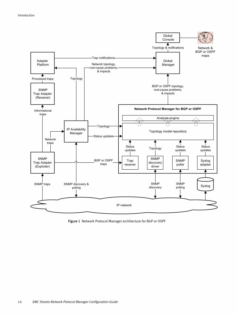
Architectural and functional overviewNetwork Protocol Manager, working with EMC Smarts IP Availability Manager (IP Availability Manager) and the EMC Smarts Service Assurance Manager (Global Manager), manages routing-protocol networks. Figure 1 on page 14 and Figure 2 on page 15 show how Network Protocol Manager interoperates with these components.
Architectural and functional overview 13
Introduction
IP network
SNMP traps SNMP discovery &polling
BGP or OSPFtraps
SNMPTrap Adapter
(Exploder)
Informationaltraps
Networktraps
IP Availability Manager
Topology
Trap notifications
Network topology,root-cause problems,
& impacts
BGP or OSPF topology,root-cause problems,
& impacts
Status updates
Topology
Adapter Platform
SNMPTrap Adapter (Receiver)
Processed traps
Syslog
Syslogadapter
Statusupdates
Trapreceiver
Statusupdates
Network &BGP or OSPF
maps
Topology & notifications
Global Console
Global Manager
Network Protocol Manager for BGP or OSPF
Topology model repository
Analysis engine
SNMPpolling
SNMPpoller
Statusupdates
SNMP discovery
SNMPdiscovery
driver
Topology
Figure 1 Network Protocol Manager architecture for BGP or OSPF
14 EMC Smarts Network Protocol Manager Configuration Guide

Introduction
IP network
SNMP traps SNMP discovery &polling
SNMPTrap Adapter
(Exploder)
Informationaltraps
Networktraps
SNMPdiscovery
driver
SNMP discovery(Juniper)
IP Availability Manager
Topology
Trap notifications
Network topology,root-cause problems,
& impacts
Topology
Status updates
Topology& CLI credentials
CLIpoller
CLI polling(Cisco)
Statusupdates
CLI discovery(Cisco)
CLIdiscovery
driver
Topology
SNMP polling(Juniper)
SNMPpoller
Statusupdates
Network Protocol Manager for EIGRP or IS-IS
Topology model repository
Analysis engine
Adapter Platform
SNMPTrap Adapter (Receiver)
Processed traps
Network & EIGRP or IS-IS
maps
Topology & notifications
Global Console
Global Manager
EIGRP or IS-IS topology,root-cause problems,
& impacts
Figure 2 Network Protocol Manager architecture for EIGRP or IS-IS
Architectural and functional overview 15
Introduction
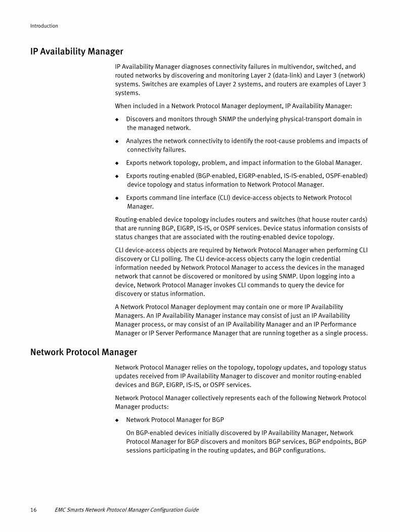
IP Availability Manager
IP Availability Manager diagnoses connectivity failures in multivendor, switched, and routed networks by discovering and monitoring Layer 2 (data-link) and Layer 3 (network) systems. Switches are examples of Layer 2 systems, and routers are examples of Layer 3 systems.
When included in a Network Protocol Manager deployment, IP Availability Manager:
◆ Discovers and monitors through SNMP the underlying physical-transport domain in the managed network.
◆ Analyzes the network connectivity to identify the root-cause problems and impacts of connectivity failures.
◆ Exports network topology, problem, and impact information to the Global Manager.
◆ Exports routing-enabled (BGP-enabled, EIGRP-enabled, IS-IS-enabled, OSPF-enabled) device topology and status information to Network Protocol Manager.
◆ Exports command line interface (CLI) device-access objects to Network Protocol Manager.
Routing-enabled device topology includes routers and switches (that house router cards) that are running BGP, EIGRP, IS-IS, or OSPF services. Device status information consists of status changes that are associated with the routing-enabled device topology.
CLI device-access objects are required by Network Protocol Manager when performing CLI discovery or CLI polling. The CLI device-access objects carry the login credential information needed by Network Protocol Manager to access the devices in the managed network that cannot be discovered or monitored by using SNMP. Upon logging into a device, Network Protocol Manager invokes CLI commands to query the device for discovery or status information.
A Network Protocol Manager deployment may contain one or more IP Availability Managers. An IP Availability Manager instance may consist of just an IP Availability Manager process, or may consist of an IP Availability Manager and an IP Performance Manager or IP Server Performance Manager that are running together as a single process.
Network Protocol Manager
Network Protocol Manager relies on the topology, topology updates, and topology status updates received from IP Availability Manager to discover and monitor routing-enabled devices and BGP, EIGRP, IS-IS, or OSPF services.
Network Protocol Manager collectively represents each of the following Network Protocol Manager products:
◆ Network Protocol Manager for BGP
On BGP-enabled devices initially discovered by IP Availability Manager, Network Protocol Manager for BGP discovers and monitors BGP services, BGP endpoints, BGP sessions participating in the routing updates, and BGP configurations.
16 EMC Smarts Network Protocol Manager Configuration Guide

Introduction
◆ Network Protocol Manager for EIGRP
On EIGRP-enabled devices initially discovered by IP Availability Manager, Network Protocol Manager for EIGRP discovers and monitors EIGRP services, EIGRP endpoints, and EIGRP sessions participating in the routing updates.
◆ Network Protocol Manager for IS-IS
On IS-IS-enabled devices initially discovered by IP Availability Manager, Network Protocol Manager for IS-IS discovers and monitors IS-IS services, IS-IS endpoints, IS-IS adjacencies participating in the routing updates, and IS-IS configurations.
◆ Network Protocol Manager for OSPF
On OSPF-enabled devices initially discovered by IP Availability Manager, Network Protocol Manager for OSPF discovers and monitors OSPF services, OSPF endpoints, OSPF adjacencies participating in the routing updates, and OSPF configurations.
Separate instances of Network Protocol Manager are required to manage the availability of each routing protocol: one each for BGP, EIGRP, IS-IS, and OSPF.
Upon importing the initial, routing-enabled device topology from IP Availability Manager, Network Protocol Manager performs its own SNMP and CLI discovery to query the devices for routing topology information. Upon building its routing topology data model, Network Protocol Manager exports the topology to the Global Manager.
Network Protocol Manager monitors the status of the routing topology by periodically SNMP- and CLI-polling the routing-enabled devices. It also subscribes to certain network topology object statuses (attributes) from IP Availability Manager.
Network Protocol Manager analyzes the received statuses to identify device and routing-protocol availability problems and impacts, and exports the results of its analysis to the Global Manager. In addition, whenever Network Protocol Manager detects a configuration-related error in a managed routing-protocol network, it exports the event to the Global Manager.
Global Manager
The Global Manager integrates the topology, problem, and impact information that is imported from IP Availability Manager and Network Protocol Manager, and relates the information to services and customers. It also provides cross-domain and end-to-end impact analysis.
The Global Manager displays the topology, problem, and impact information through the Global Console.
Adapter Platform
The EMC Smarts Service Assurance Manager Adapter Platform (Adapter Platform) is an optional component in a Network Protocol Manager deployment. The Adapter Platform is included in the deployment only if the customer wants to forward informational traps to the Global Manager for display in the Global Console.
Architectural and functional overview 17

Introduction
The Adapter Platform imports and normalizes topology from IP Availability Manager, and imports and normalizes events of interest from EMC Smarts adapters such as the SNMP Trap Adapter. Normalize means to convert topology or event information into a common form that is understood by the Global Manager. The normalized event information is transferred as EMC Smarts notifications to the Global Manager.
An Adapter Platform feature, called the Topology Importer, collects hostnames and IP addresses from IP Availability Manager so that the Adapter Platform can accurately place events in their topological context. The Adapter Platform updates this list as the information changes in IP Availability Manager.
Global Console
The Global Console provides a graphical user interface for configuration and administration of Global Managers, Adapter Platforms, Domain Managers, and externally running EMC Smarts adapters such as the SNMP Trap Adapter.
When the Global Console is attached to the Global Manager, a user can browse the topology in various forms, including maps, and view notifications about problems that impact availability and performance.
EMC Smarts Broker
The EMC Smarts Broker facilitates Global Console connections to the component applications in an EMC Smarts system deployment.
When a user starts a Global Console process, the process connects to the Broker and launches a dialog box through which the user views and selects any component application that is registered with the Broker. After the user selects an application, the Global Console connects to the application and disconnects from the Broker.
Configuration roadmapThe following sections highlight the configuration tasks that are associated with the setup of the components in a Network Protocol Manager deployment. These tasks involve configuring the Network Protocol Manager, IP Availability Manager, Global Manager, and (optional) Adapter Platform applications that are part of the deployment.
Some configuration tasks are performed before the applications are started, such as the editing of configuration files, and some are performed through the Global Console when the applications are up and running.
Network Protocol Manager configuration tasks
Configuring Network Protocol Manager consists of the following tasks:
◆ Configure SNMP trap integration to distribute BGP- or OSPF-related trap messages to Network Protocol Manager for processing (optional).
Chapter 2, “Setting Configuration Parameters,” and Chapter 6, “Configuring SNMP Trap Integration,” provide the procedures for completing this task.
◆ Configure syslog message forwarding to forward BGP- or OSPF-related syslog messages to Network Protocol Manager for processing (optional).
18 EMC Smarts Network Protocol Manager Configuration Guide
Introduction
Chapter 2, “Setting Configuration Parameters,” and Chapter 7, “Configuring Syslog Message Processing and Forwarding,” provide the procedures for completing this task.
◆ Configure Secure Shell (SSH) clients and servers to enable Network Protocol Manager to perform CLI discovery and CLI polling over a secure connection (optional).
Chapter 8, “Configuring SSH Security,” provides the procedures for completing this task.
◆ Configure SNMP polling and CLI polling (optional).
Chapter 10, “Configuring Polling and Threshold Groups,” provides the procedures for completing this task.
◆ Add IP Availability Manager as a source from which Network Protocol Manager imports topology and status updates (mandatory).
The EMC Smarts Network Protocol Manager Discovery Guide provides the instructions for completing this task.
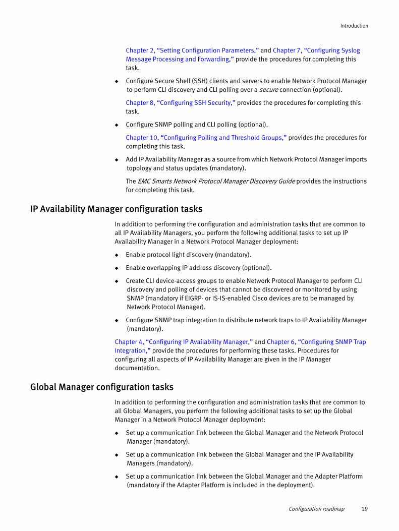
IP Availability Manager configuration tasks
In addition to performing the configuration and administration tasks that are common to all IP Availability Managers, you perform the following additional tasks to set up IP Availability Manager in a Network Protocol Manager deployment:
◆ Enable protocol light discovery (mandatory).
◆ Enable overlapping IP address discovery (optional).
◆ Create CLI device-access groups to enable Network Protocol Manager to perform CLI discovery and polling of devices that cannot be discovered or monitored by using SNMP (mandatory if EIGRP- or IS-IS-enabled Cisco devices are to be managed by Network Protocol Manager).
◆ Configure SNMP trap integration to distribute network traps to IP Availability Manager (mandatory).
Chapter 4, “Configuring IP Availability Manager,” and Chapter 6, “Configuring SNMP Trap Integration,” provide the procedures for performing these tasks. Procedures for configuring all aspects of IP Availability Manager are given in the IP Manager documentation.
Global Manager configuration tasks
In addition to performing the configuration and administration tasks that are common to all Global Managers, you perform the following additional tasks to set up the Global Manager in a Network Protocol Manager deployment:
◆ Set up a communication link between the Global Manager and the Network Protocol Manager (mandatory).
◆ Set up a communication link between the Global Manager and the IP Availability Managers (mandatory).
◆ Set up a communication link between the Global Manager and the Adapter Platform (mandatory if the Adapter Platform is included in the deployment).
Configuration roadmap 19
Introduction
◆ Enable access to the BGP, EIGRP, IS-IS, and OSPF maps (optional).
Chapter 5, “Configuring the Global Manager,” provides the procedures for performing these tasks. Procedures for configuring all aspects of the Global Manager are given in the EMC Smarts Service Assurance Manager Configuration Guide.
Adapter Platform configuration tasks (optional)
Only if you want to forward informational traps to the Global Manager for display as EMC Smarts notifications in the Global Console do you include the Adapter Platform in your Network Protocol Manager deployment.
If you decide to include the Adapter Platform, Chapter 6, “Configuring SNMP Trap Integration,” provides the procedure for configuring the Adapter Platform to receive, convert, and forward traps to the Global Manager. Procedures for configuring all aspects of the Adapter Platform and the SNMP Trap Adapter are given in the EMC Smarts Service Assurance Manager Adapter Platform User Guide.
What to do after configurationUpon configuring your Network Protocol Manager deployment, you are ready to begin the discovery. To understand, prepare for, and initiate Network Protocol Manager discovery, consult the EMC Smarts Network Protocol Manager Discovery Guide.
After the discovery, consult the individual user guides (BGP, EIGRP, IS-IS, OSPF) for Network Protocol Manager to understand Network Protocol Manager monitoring and analysis.
20 EMC Smarts Network Protocol Manager Configuration Guide
CHAPTER 2Setting Configuration Parameters
This chapter identifies Network Protocol Manager configuration parameters that are relevant to discovery, describes their settings, and provides instructions for changing their settings. It consists of the following sections:
◆ Domain Manager configuration directories.............................................................. 22◆ User configuration parameters ................................................................................ 23◆ Methods to modify user configuration parameters .................................................. 23◆ Description of bgp.conf........................................................................................... 27◆ Description of eigrp.conf......................................................................................... 30◆ Description of isis.conf ........................................................................................... 31◆ Description of ospf.conf.......................................................................................... 33◆ Description of perl-cli.conf ...................................................................................... 35◆ EMC Smarts secure communications....................................................................... 36◆ Description of perl-cli.conf ...................................................................................... 35◆ EMC Smarts secure communications....................................................................... 36
Setting Configuration Parameters 21

Setting Configuration Parameters
Domain Manager configuration directoriesThe Network Protocol Manager installation directory contains the four Domain Manager configuration directories that are shown in Figure 3 on page 22.
Network Protocol Managerfor EIGRP
configuration directory
Network Protocol Managerfor IS-IS
configuration directory
bgp eigrp isis ospf
BASEDIR
conf
smarts
Network Protocol Managerfor BGP
configuration directory
Network Protocol Managerfor OSPF
configuration directory
Figure 3 Domain Manager configuration directories for Network Protocol Manager
BASEDIR, which is not an environment variable, is used in documentation to represent the top-level directory structure of an EMC Smarts product installation. For the Network Protocol Manager, BASEDIR represents <root_dir>/NPM.
Each configuration directory in Figure 3 on page 22 contains the bootstrap and configuration files for its associated Domain Manager. The --config option in a Domain Manager startup command points to the appropriate configuration directory:
◆ The --config=bgp option in a Network Protocol Manager for BGP startup command points to the bootstrap and configuration files in the bgp directory. The default name of Network Protocol Manager for BGP is INCHARGE-BGP.
◆ The --config=eigrp option in a Network Protocol Manager for EIGRP startup command points to the bootstrap and configuration files in the eigrp directory. The default name of Network Protocol Manager for EIGRP is INCHARGE-EIGRP.
◆ The --config=isis option in a Network Protocol Manager for IS-IS startup command points to the bootstrap and configuration files in the isis directory. The default name of Network Protocol Manager for IS-IS is INCHARGE-ISIS.
◆ The --config=ospf option in a Network Protocol Manager for OSPF startup command points to the bootstrap and configuration files in the ospf directory. The default name of Network Protocol Manager for OSPF is INCHARGE-OSPF.
The bootstrap and configuration files for a Domain Manager set up the environment for the Domain Manager.
22 EMC Smarts Network Protocol Manager Configuration Guide
Setting Configuration Parameters
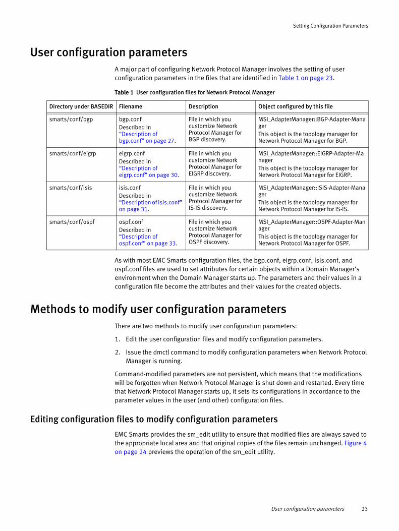
User configuration parametersA major part of configuring Network Protocol Manager involves the setting of user configuration parameters in the files that are identified in Table 1 on page 23.
Table 1 User configuration files for Network Protocol Manager
Directory under BASEDIR Filename Description Object configured by this file
As with most EMC Smarts configuration files, the bgp.conf, eigrp.conf, isis.conf, and ospf.conf files are used to set attributes for certain objects within a Domain Manager’s environment when the Domain Manager starts up. The parameters and their values in a configuration file become the attributes and their values for the created objects.
Methods to modify user configuration parametersThere are two methods to modify user configuration parameters:
1. Edit the user configuration files and modify configuration parameters.
2. Issue the dmctl command to modify configuration parameters when Network Protocol Manager is running.
Command-modified parameters are not persistent, which means that the modifications will be forgotten when Network Protocol Manager is shut down and restarted. Every time that Network Protocol Manager starts up, it sets its configurations in accordance to the parameter values in the user (and other) configuration files.
Editing configuration files to modify configuration parameters
EMC Smarts provides the sm_edit utility to ensure that modified files are always saved to the appropriate local area and that original copies of the files remain unchanged. Figure 4 on page 24 previews the operation of the sm_edit utility.
smarts/conf/bgp bgp.confDescribed in “Description of bgp.conf” on page 27.
File in which you customize Network Protocol Manager for BGP discovery.
MSI_AdapterManager::BGP-Adapter-ManagerThis object is the topology manager for Network Protocol Manager for BGP.
smarts/conf/eigrp eigrp.confDescribed in “Description of eigrp.conf” on page 30.
File in which you customize Network Protocol Manager for EIGRP discovery.
MSI_AdapterManager::EIGRP-Adapter-ManagerThis object is the topology manager for Network Protocol Manager for EIGRP.
smarts/conf/isis isis.confDescribed in “Description of isis.conf” on page 31.
File in which you customize Network Protocol Manager for IS-IS discovery.
MSI_AdapterManager::ISIS-Adapter-ManagerThis object is the topology manager for Network Protocol Manager for IS-IS.
smarts/conf/ospf ospf.confDescribed in “Description of ospf.conf” on page 33.
File in which you customize Network Protocol Manager for OSPF discovery.
MSI_AdapterManager::OSPF-Adapter-ManagerThis object is the topology manager for Network Protocol Manager for OSPF.
User configuration parameters 23

Setting Configuration Parameters
BASEDIR<root_dir> BASEDIR/smarts/conf BASEDIR/smarts/local/conf
Location ofcommands & utilities
Location of originalconfiguration files
Location of modifiedconfiguration files
* The dasl directory appears only in a Network Protocol Manager installation on a Windows system.
* *
.... .. .. .
Figure 4 Preview of how the sm_edit utility works
All EMC Smarts products use the same basic installation directory structure that is shown in Figure 4 on page 24.
To invoke the sm_edit utility, go to the BASEDIR/smarts/bin directory and specify the path and the name of the file, relative to the BASEDIR/smarts directory, that you want to edit. For example,
sm_edit conf/bgp/bgp.conf
opens in a text editor either a local copy of the bgp.conf file in BASEDIR/smarts/local/conf/bgp or an original copy of the bgp.conf file in BASEDIR/smarts/conf/bgp if no local copy exists.
After you modify and save the bgp.conf file, the sm_edit utility saves the modified version of the file to the BASEDIR/smarts/local/conf/bgp directory.
24 EMC Smarts Network Protocol Manager Configuration Guide

Setting Configuration Parameters
You can use the sm_edit utility to edit any text file, not just a configuration file, in the BASEDIR/smarts or BASEDIR/smarts/local directory. Because sm_edit assumes a starting point of BASEDIR/smarts, the text-file path that you specify begins with the directory name (conf, rules, script, and so on) under the BASEDIR/smarts directory.
Original versions of files may be changed or updated as part of an EMC Smarts software upgrade. However, files in the BASEDIR/smarts/local directory are retained during an upgrade.
The EMC Smarts System Administration Guide provides additional information about the sm_edit utility.
Issuing the dmctl command to modify configuration parameters
In general, you can use the following dmctl command to change the value of any basic-type attribute (string, boolean, integer, float, and so on) of any EMC Smarts object:
dmctl -s <Domain Manager instance name> put <class::instance::attribute> <value>
The dmctl utility is described in the HTML pages that are located in the BASEDIR/smarts/doc/html/usage directory of any Domain Manager installation area.
Upon issuing a dmctl command, you might be prompted for a username and password. Respond with your user account. For example, to specify the default administrative account, enter username admin and password changeme.
For Network Protocol Manager, you use the dmctl put command to override parameter settings in the bgp.conf file, the eigrp.conf file, the isis.conf file, and the ospf.conf file.
Temporary versus permanent changeThe use of the dmctl command to override a parameter value in a configuration file is temporary in the following sense: When the Domain Manager is restarted, it reads the original parameter value in the configuration file. To make the change permanent, use the sm_edit utility to change the parameter value in the configuration file.
ExampleAs an example of using the dmctl command, you can issue the following dmctl command from the BASEDIR/smarts/bin directory to override the AdminDownFlag parameter value in the bgp.conf file:
dmctl -s INCHARGE-BGP put MSI_AdapterManager::BGP-Adapter-Manager::AdminDownFlag TRUE
The parameters in the bgp.conf file are defined as attributes of the BGP-Adapter-Manager object, which is an instance of the MSI_AdapterManager class. The BGP-Adapter-Manager object is not saved to disk, that is, is not saved to a Network Protocol Manager for BGP repository file in the BASEDIR/smarts/local/repos/icf directory.
Methods to modify user configuration parameters 25

Setting Configuration Parameters
More examplesAs further examples, you can issue the following dmctl commands from the BASEDIR/smarts/bin directory to override the AdminDownFlag parameter value in the eigrp.conf, isis.conf, and ospf.conf files:
dmctl -s INCHARGE-EIGRP put MSI_AdapterManager::EIGRP-Adapter-Manager::AdminDownFlag TRUE
dmctl -s INCHARGE-ISIS put MSI_AdapterManager::ISIS-Adapter-Manager::AdminDownFlag TRUE
dmctl -s INCHARGE-OSPF put MSI_AdapterManager::OSPF-Adapter-Manager::AdminDownFlag TRUE
As with the BGP-Adapter-Manager object, the EIGRP-Adapter-Manager, ISIS-Adapter-Manager, and OSPF-Adapter-Manager objects are not saved to disk, that is, are not saved to individual Network Protocol Manager repository files in the BASEDIR/smarts/local/repos/icf directory.
LimitationsAlthough you can use the dmctl command to override parameter values in the bgp.conf, eigrp.conf, isis.conf, or ospf.conf file, your changes might not take effect because Network Protocol Manager reads some parameters only at startup.
For example, even if you issue the dmctl command to override the TrapPort or SyslogName setting in the bgp.conf file, your change will not be known to the target Network Protocol Manager for BGP until you:
1. Use the sm_edit utility to make the change to the TrapPort or SyslogName parameter in the bgp.conf file.
2. Restart the target Network Protocol Manager for BGP.
26 EMC Smarts Network Protocol Manager Configuration Guide

Setting Configuration Parameters
Description of bgp.confThe bgp.conf file contains configuration parameters that you edit to customize Network Protocol Manager for BGP discovery. The parameters are a subset of attributes that are defined for the topology manager (BGP-Adapter-Manager) that will run in the Network Protocol Manager for BGP environment.
Table 2 on page 27 describes the parameters in the bgp.conf file. The parameters and their values are case-sensitive.
Table 2 Parameters in the bgp.conf file (page 1 of 3)
Parameter Value Description
Config Regular expression: bgp Identifies this Domain Manager configuration as Network Protocol Manager for BGP.
Note: Do not change this parameter.
TrapPort 0, 162, 2049 to 65534Default: 0
Enables the Network Protocol Manager for BGP built-in trap receiver, and specifies the port used by the trap receiver to receive traps.• TrapPort = 0 disables the built-in trap receiver.• TrapPort = 162 or a value in the range 2049-to-65534
(inclusive) enables the built-in trap receiver and sets the trap port to the value specified for the parameter.
“Procedure to configure the Network Protocol Manager built-in trap receiver” on page 89 clarifies the use of this parameter.
TraceTraps TRUE, FALSEDefault: FALSE
Determines whether trap receiver tracing for Network Protocol Manager for BGP is enabled or disabled.• A value of TRUE indicates that trap receiver tracing is
enabled.• A value of FALSE indicates that trap receiver tracing is
disabled.
SyslogName Regular expressionDefault: empty string
Enables the Network Protocol Manager for BGP built-in syslog adapter, and specifies the name of the local syslog file to be tailed by the syslog adapter.• SyslogName = "" (empty string) disables the built-in
syslog adapter.• SyslogName = <full path and name of syslog file> (for
example, /var/adm/messages) enables the built-in syslog adapter and sets the name of the local syslog file to be tailed to the value specified for the parameter.
Chapter 7, “Configuring Syslog Message Processing and Forwarding,” clarifies the use of this parameter.
TraceSyslog TRUE, FALSEDefault: FALSE
Determines whether syslog adapter tracing for Network Protocol Manager for BGP is enabled or disabled.• A value of TRUE indicates that syslog adapter tracing is
enabled.• A value of FALSE indicates that syslog adapter tracing is
disabled.
Description of bgp.conf 27

Setting Configuration Parameters
AdminDownFlag TRUE, FALSEDefault: FALSE
Controls whether Network Protocol Manager for BGP generates alarms on the BGP sessions of BGP protocol endpoints that are administratively down (manually disabled).• A value of TRUE indicates that alarms are not generated
on the BGP sessions.• A value of FALSE indicates that alarms are generated on
the BGP sessions.
IsDisplayNameCustom TRUE, FALSEDefault: FALSE
Controls whether Network Protocol Manager for BGP accepts topology objects from EMC Smarts Adapter for Alcatel-Lucent 5620 SAM EMS (the Adapter).• A value of TRUE indicates that topology objects from the
Adapter are accepted.• A value of FALSE indicates that topology objects from the
Adapter are not accepted.When the Adapter is present, set the IsDisplayNameCustom parameter to TRUE. The Adapter is described in the EMC Smarts Adapter for Alcatel-Lucent 5620 SAM EMS User Guide.
EnableRRDiscovery TRUE, FALSEDefault: FALSE
Controls whether Network Protocol Manager for BGP discovers Route Reflectors.• A value of TRUE indicates that Route Reflectors are
discovered.• A value of FALSE indicates that Route Reflectors are not
discovered.To discover Route Reflectors, set the EnableRRDiscovery parameter to TRUE.
Note: A Route Reflector is an Internal BGP (IBGP) peer router that passes IBGP learned routes to a set of IBGP neighbors.
DisableBGPAlertsOnSNMPError
TRUE, FALSEDefault: FALSE
Controls whether Network Protocol Manager for BGP should ignore • TRUE — A value of TRUE SNMP error gets ignored• FALSE
DisableAlertsOnCLIError TRUE, FALSEDefault: FALSE
Controls whether Network Protocol Manager for BGP should ignore the CLI errors.• TRUE — Disables the alerts on CLI errors.• FALSE— Enables the alerts on CLI errors.
EnableIPv6Discovery TRUE, FALSEDefault: TRUE
Controls the discovery of IPv6 topology by Network Protocol Manager for BGP.• TRUE — Enables IPv6 topology discovery.• FALSE— Disables IPv6 IPv6 topology discovery.
Note: Applicable only for BGP, OSPF and IS-IS.
Table 2 Parameters in the bgp.conf file (page 2 of 3)
Parameter Value Description
28 EMC Smarts Network Protocol Manager Configuration Guide
Setting Configuration Parameters
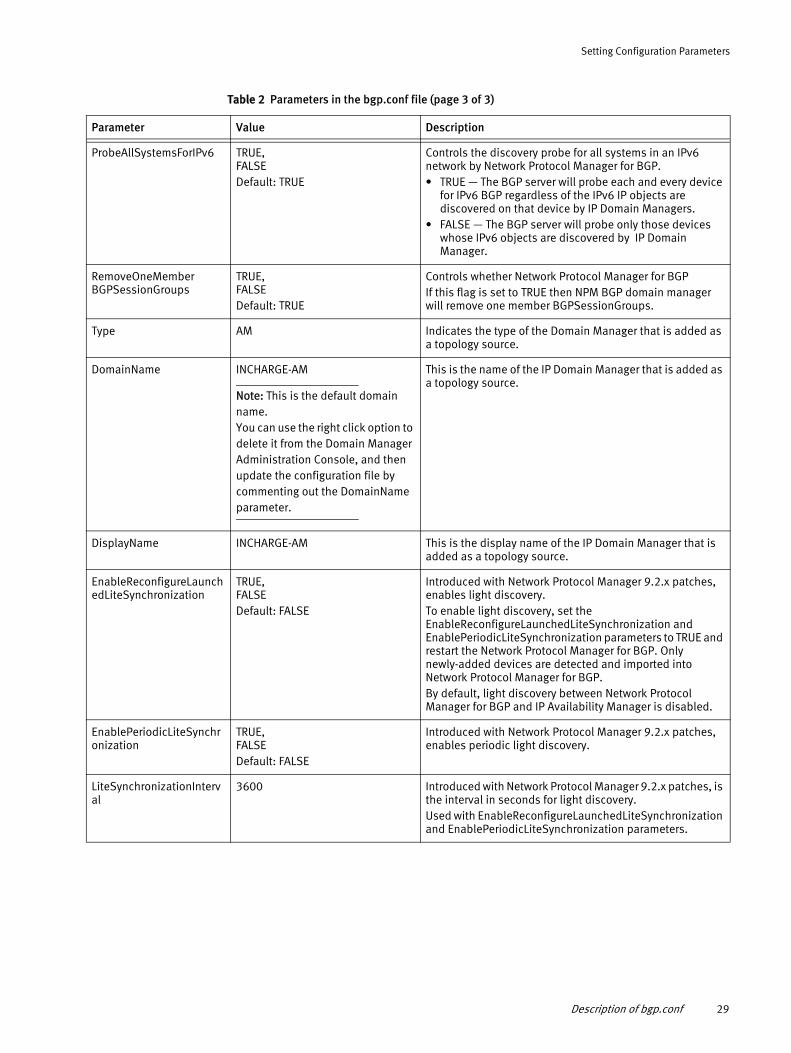
ProbeAllSystemsForIPv6 TRUE, FALSEDefault: TRUE
Controls the discovery probe for all systems in an IPv6 network by Network Protocol Manager for BGP.• TRUE — The BGP server will probe each and every device
for IPv6 BGP regardless of the IPv6 IP objects are discovered on that device by IP Domain Managers.
• FALSE — The BGP server will probe only those devices whose IPv6 objects are discovered by IP Domain Manager.
RemoveOneMember BGPSessionGroups
TRUE, FALSEDefault: TRUE
Controls whether Network Protocol Manager for BGP If this flag is set to TRUE then NPM BGP domain manager will remove one member BGPSessionGroups.
Type AM Indicates the type of the Domain Manager that is added as a topology source.
DomainName INCHARGE-AM
Note: This is the default domain name. You can use the right click option to delete it from the Domain Manager Administration Console, and then update the configuration file by commenting out the DomainName parameter.
This is the name of the IP Domain Manager that is added as a topology source.
DisplayName INCHARGE-AM This is the display name of the IP Domain Manager that is added as a topology source.
EnableReconfigureLaunchedLiteSynchronization
TRUE, FALSEDefault: FALSE
Introduced with Network Protocol Manager 9.2.x patches, enables light discovery. To enable light discovery, set the EnableReconfigureLaunchedLiteSynchronization and EnablePeriodicLiteSynchronization parameters to TRUE and restart the Network Protocol Manager for BGP. Only newly-added devices are detected and imported into Network Protocol Manager for BGP.By default, light discovery between Network Protocol Manager for BGP and IP Availability Manager is disabled.
EnablePeriodicLiteSynchronization
TRUE, FALSEDefault: FALSE
Introduced with Network Protocol Manager 9.2.x patches, enables periodic light discovery.
LiteSynchronizationInterval
3600 Introduced with Network Protocol Manager 9.2.x patches, is the interval in seconds for light discovery.Used with EnableReconfigureLaunchedLiteSynchronization and EnablePeriodicLiteSynchronization parameters.
Table 2 Parameters in the bgp.conf file (page 3 of 3)
Parameter Value Description
Description of bgp.conf 29
Setting Configuration Parameters
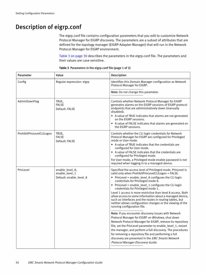
Description of eigrp.confThe eigrp.conf file contains configuration parameters that you edit to customize Network Protocol Manager for EIGRP discovery. The parameters are a subset of attributes that are defined for the topology manager (EIGRP-Adapter-Manager) that will run in the Network Protocol Manager for EIGRP environment.
Table 3 on page 30 describes the parameters in the eigrp.conf file. The parameters and their values are case-sensitive.
Table 3 Parameters in the eigrp.conf file (page 1 of 2)
Parameter Value Description
Config Regular expression: eigrp Identifies this Domain Manager configuration as Network Protocol Manager for EIGRP.
Note: Do not change this parameter.
AdminDownFlag TRUE, FALSEDefault: FALSE
Controls whether Network Protocol Manager for EIGRP generates alarms on the EIGRP sessions of EIGRP protocol endpoints that are administratively down (manually disabled).• A value of TRUE indicates that alarms are not generated
on the EIGRP sessions.• A value of FALSE indicates that alarms are generated on
the EIGRP sessions.
ProhibitPrivLevelCLILogon TRUE, FALSEDefault: FALSE
Controls whether the CLI login credentials for Network Protocol Manager for EIGRP are configured for Privileged mode or User mode.• A value of TRUE indicates that the credentials are
configured for User mode.• A value of FALSE indicates that the credentials are
configured for Privileged mode.For User mode, a Privileged-mode enable password is not required when logging in to a managed device.
PrivLevel enable_level_8, enable_level_1Default: enable_level_8
Specified the access level of Privileged mode. PrivLevel is valid only when ProhibitPrivLevelCLILogon = FALSE.• PrivLevel = enable_level_8 configures the CLI login
credentials for Privileged mode 8.• PrivLevel = enable_level_1 configures the CLI login
credentials for Privileged mode 1.Level 1 access is more restrictive than level 8 access. Both allow access to some information about a managed device, such as interfaces and the routes in routing tables, but neither allows configuration changes or the viewing of the running configuration file.
Note: If you encounter discovery issues with Network Protocol Manager for EIGRP on Windows, shut down Network Protocol Manager for EIGRP, remove its repository file, set the PrivLevel parameter to enable_level_1, restart the manager, and perform a full discovery. The procedures for removing a repository file and performing a full discovery are presented in the EMC Smarts Network Protocol Manager Discovery Guide.
30 EMC Smarts Network Protocol Manager Configuration Guide
Setting Configuration Parameters
Description of isis.confThe isis.conf file contains configuration parameters that you edit to customize Network Protocol Manager for IS-IS discovery. The parameters are a subset of attributes that are defined for the topology manager (ISIS-Adapter-Manager) that will run in the Network Protocol Manager for IS-IS environment.
Table 4 on page 31 describes the parameters in the isis.conf file. The parameters and their values are case-sensitive.
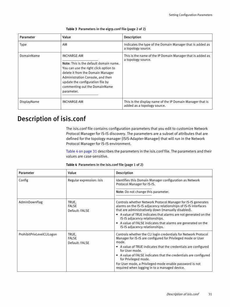
Type AM Indicates the type of the Domain Manager that is added as a topology source.
DomainName INCHARGE-AM
Note: This is the default domain name. You can use the right click option to delete it from the Domain Manager Administration Console, and then update the configuration file by commenting out the DomainName parameter.
This is the name of the IP Domain Manager that is added as a topology source.
DisplayName INCHARGE-AM This is the display name of the IP Domain Manager that is added as a topology source.
Table 3 Parameters in the eigrp.conf file (page 2 of 2)
Parameter Value Description
Table 4 Parameters in the isis.conf file (page 1 of 2)
Parameter Value Description
Config Regular expression: isis Identifies this Domain Manager configuration as Network Protocol Manager for IS-IS.
Note: Do not change this parameter.
AdminDownFlag TRUE, FALSEDefault: FALSE
Controls whether Network Protocol Manager for IS-IS generates alarms on the IS-IS adjacency relationships of IS-IS interfaces that are administratively down (manually disabled).• A value of TRUE indicates that alarms are not generated on the
IS-IS adjacency relationships.• A value of FALSE indicates that alarms are generated on the
IS-IS adjacency relationships.
ProhibitPrivLevelCLILogon TRUE, FALSEDefault: FALSE
Controls whether the CLI login credentials for Network Protocol Manager for IS-IS are configured for Privileged mode or User mode.• A value of TRUE indicates that the credentials are configured
for User mode.• A value of FALSE indicates that the credentials are configured
for Privileged mode.For User mode, a Privileged-mode enable password is not required when logging in to a managed device.
Description of isis.conf 31

Setting Configuration Parameters
PrivLevel enable_level_8, enable_level_1Default: enable_level_8
Specified the access level of Privileged mode. PrivLevel is valid only when ProhibitPrivLevelCLILogon = FALSE.• PrivLevel = enable_level_8 configures the CLI login
credentials for Privileged mode 8.• PrivLevel = enable_level_1 configures the CLI login
credentials for Privileged mode 1.Level 1 access is more restrictive than level 8 access. Both allow access to some information about a managed device, such as interfaces and the routes in routing tables, but neither allows configuration changes or the viewing of the running configuration file.
Note: If you encounter discovery issues with Network Protocol Manager for IS-IS on Windows, shut down Network Protocol Manager for IS-IS, remove its repository file, set the PrivLevel parameter to enable_level_1, restart the manager, and perform a full discovery. The procedures for removing a repository file and performing a full discovery are presented in the EMC Smarts Network Protocol Manager Discovery Guide.
EnableIPv6Discovery TRUE, FALSEDefault: TRUE
Determines the discovery of IPv6 topology by Network Protocol Manager for ISIS.• TRUE — Discovers IPv6 topology• FALSE— Does not discover the IPv6 topology.
Note: Applicable only for BGP, OSPF and IS-IS.
Type AM Indicates the type of the Domain Manager that is added as a topology source.
DomainName INCHARGE-AM
Note: This is the default domain name. You can use the right click option to delete it from the Domain Manager Administration Console, and then update the configuration file by commenting out the DomainName parameter.
This is the name of the IP Domain Manager that is added as a topology source.
DisplayName INCHARGE-AM This is the display name of the IP Domain Manager that is added as a topology source.
Table 4 Parameters in the isis.conf file (page 2 of 2)
Parameter Value Description
32 EMC Smarts Network Protocol Manager Configuration Guide

Setting Configuration Parameters
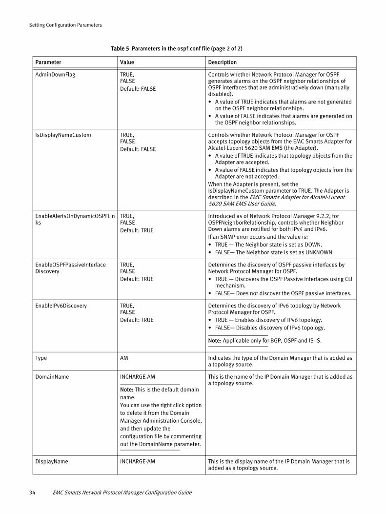
Description of ospf.confThe ospf.conf file contains configuration parameters that you edit to customize Network Protocol Manager for OSPF discovery. The parameters are a subset of attributes that are defined for the topology manager (OSPF-Adapter-Manager) that will run in the Network Protocol Manager for OSPF environment.
Table 5 on page 33 describes the parameters in the ospf.conf file. The parameters and their values are case-sensitive.
Table 5 Parameters in the ospf.conf file (page 1 of 2)
Parameter Value Description
Config Regular expression: ospf Identifies this Domain Manager configuration as Network Protocol Manager for OSPF.
Note: Do not change this parameter.
TrapPort 0, 162, 2049 to 65534Default: 0
Enables the Network Protocol Manager for OSPF built-in trap receiver, and specifies the port used by the trap receiver to receive traps.• TrapPort = 0 disables the built-in trap receiver.• TrapPort = 162 or a value in the range 2049-to-65534
(inclusive) enables the built-in trap receiver and sets the trap port to the value specified for the parameter.
“Procedure to configure the Network Protocol Manager built-in trap receiver” on page 89 clarifies the use of this parameter.
TraceTraps TRUE, FALSEDefault: FALSE
Determines whether trap receiver tracing for Network Protocol Manager for OSPF is enabled or disabled.• A value of TRUE indicates that trap receiver tracing is
enabled.• A value of FALSE indicates that trap receiver tracing is
disabled.
SyslogName Regular expressionDefault: empty string
Enables the Network Protocol Manager for OSPF built-in syslog adapter, and specifies the name of the local syslog file to be tailed by the syslog adapter.• SyslogName = "" (empty string) disables the built-in
syslog adapter.• SyslogName = <full path and name of syslog file> (for
example, /var/adm/messages) enables the built-in syslog adapter and sets the name of the local syslog file to be tailed to the value specified for the parameter.
Chapter 7, “Configuring Syslog Message Processing and Forwarding,” clarifies the use of this parameter.
TraceSyslog TRUE, FALSEDefault: FALSE
Determines whether syslog adapter tracing for Network Protocol Manager for OSPF is enabled or disabled.• A value of TRUE indicates that syslog adapter tracing is
enabled.• A value of FALSE indicates that syslog adapter tracing is
disabled.
Description of ospf.conf 33
Setting Configuration Parameters
AdminDownFlag TRUE, FALSEDefault: FALSE
Controls whether Network Protocol Manager for OSPF generates alarms on the OSPF neighbor relationships of OSPF interfaces that are administratively down (manually disabled).• A value of TRUE indicates that alarms are not generated
on the OSPF neighbor relationships.• A value of FALSE indicates that alarms are generated on
the OSPF neighbor relationships.
IsDisplayNameCustom TRUE, FALSEDefault: FALSE
Controls whether Network Protocol Manager for OSPF accepts topology objects from the EMC Smarts Adapter for Alcatel-Lucent 5620 SAM EMS (the Adapter).• A value of TRUE indicates that topology objects from the
Adapter are accepted.• A value of FALSE indicates that topology objects from the
Adapter are not accepted.When the Adapter is present, set the IsDisplayNameCustom parameter to TRUE. The Adapter is described in the EMC Smarts Adapter for Alcatel-Lucent 5620 SAM EMS User Guide.
EnableAlertsOnDynamicOSPFLinks
TRUE, FALSEDefault: TRUE
Introduced as of Network Protocol Manager 9.2.2, for OSPFNeighborRelationship, controls whether Neighbor Down alarms are notified for both IPv4 and IPv6.If an SNMP error occurs and the value is:• TRUE — The Neighbor state is set as DOWN.• FALSE— The Neighbor state is set as UNKNOWN.
EnableOSPFPassiveInterface Discovery
TRUE, FALSEDefault: TRUE
Determines the discovery of OSPF passive interfaces by Network Protocol Manager for OSPF.• TRUE — Discovers the OSPF Passive Interfaces using CLI
mechanism.• FALSE— Does not discover the OSPF passive interfaces.
EnableIPv6Discovery TRUE, FALSEDefault: TRUE
Determines the discovery of IPv6 topology by Network Protocol Manager for OSPF.• TRUE — Enables discovery of IPv6 topology.• FALSE— Disables discovery of IPv6 topology.
Note: Applicable only for BGP, OSPF and IS-IS.
Type AM Indicates the type of the Domain Manager that is added as a topology source.
DomainName INCHARGE-AM
Note: This is the default domain name. You can use the right click option to delete it from the Domain Manager Administration Console, and then update the configuration file by commenting out the DomainName parameter.
This is the name of the IP Domain Manager that is added as a topology source.
DisplayName INCHARGE-AM This is the display name of the IP Domain Manager that is added as a topology source.
Table 5 Parameters in the ospf.conf file (page 2 of 2)
Parameter Value Description
34 EMC Smarts Network Protocol Manager Configuration Guide

Setting Configuration Parameters
Description of perl-cli.confThe perl-cli.conf file contains the list of parameters for Perl, Telnet and SSH discovery. The perl-cli.conf file is located at BASEDIR/smarts/conf/<bgp/isis/ospf/eigrp>. Table 6 on page 35 describes the parameters in the perl-cli.conf file.
For any entry in the perl-cli.conf file, do not enclose the name or value in quotes, and do not punctuate the entry with commas, semicolons, or periods.
Table 6 Parameters in the perl-cli.conf file
Parameter Value Description
ip_versions The values can be:• v4 — To use IPv4 addresses only.• v6—To use IPv6 addresses only.• v4v6—To use IPv4 addresses first, and then
IPv6 addresses. (Default)• v6v4—To use IPv6 addresses first, and then use
IPv4 addresses.• any—To use any type of IP address.
Note: If you are running the NPM server in Windows, do not use the value: ip_versions=any
Determines what type of IP address to use when establishing the CLI connection between the NPM server and the device.
Note: The CLI connection is Perl-based, and not DASL based.
timeout Default: 10 seconds This is the timeout for establishing the connection from NPM server to the device.
get_timeout Default: 0.1 seconds Determines the time to fetch the information from the device through CLI.
read_timeout Default: 0.1 seconds Determines the time to read the information from the device through CLI.
debug Default: 0• 1—Enables debugging• 0—Disables debugging
Determines the generation of CLI log files in the NPM server log directory.
ssh_client Default location: /usr/bin/ssh Specifies the location of the SSH client in your system.
Description of perl-cli.conf 35

Setting Configuration Parameters
EMC Smarts secure communicationsThe security configuration files, clientConnect.conf and serverConnect.conf, located in the BASEDIR/smarts/conf directory of each EMC Smarts software installation, enable you to set up secure connections between the component applications in a Network Protocol Manager deployment. By default, the configuration option settings in the clientConnect.conf file and the serverConnect.conf files enable minimally secure connections between the components.
A Network Protocol Manager deployment that employs secure communications has the following environment variables set to the same value in each component application’s BASEDIR/smarts/local/conf/runcmd_env.sh file:
SM_INCOMING_PROTOCOL=[1,0 or 2,0 or 3,0]SM_OUTGOING_PROTOCOL=[1,0 or 2,0 or 3,0]
For example:
SM_INCOMING_PROTOCOL=2,0SM_OUTGOING_PROTOCOL=2,0
The EMC Smarts System Administration Guide presents detailed information about EMC Smarts secure communications.
36 EMC Smarts Network Protocol Manager Configuration Guide

CHAPTER 3Opening the Global Console
This chapter includes procedures for opening the Global Console and describes console views. It consists of the following sections:
◆ Global Console overview......................................................................................... 38◆ User accounts and passwords................................................................................. 38◆ Procedure for opening the Global Console .............................................................. 39◆ Procedure for opening the Global Manager Administration Console ........................ 41◆ Procedure for opening the Domain Manager Administration Console ...................... 41◆ Procedure for opening the Polling and Thresholds Console ..................................... 42
Opening the Global Console 37
Opening the Global Console
Global Console overviewThe Global Console is a collection of many consoles, or console views, that together enable administrators to manage EMC Smarts Domain Managers and Global Managers.
You will use the following three consoles to complete the configuration and administration tasks that are required to set up a Network Protocol Manager deployment:
◆ Domain Manager Administration Console
Enables administrators to manage Domain Managers and to discover topology; for example, to add IP Availability Manager as a source to a Domain Manager.
Using the Domain Manager Administration Console to add IP Availability Manager as a source to Network Protocol Manager is described in the EMC Smarts Network Protocol Manager Discovery Guide.
◆ Global Manager Administration Console
Enables administrators to configure the Global Manager; for example, to set up connections to underlying Domain Managers, to enable map types that are disabled by default, or to enable server tools that are disabled by default.
◆ Polling and Thresholds Console
Enables administrators to control periodic polling, to set thresholds for polled data, and to deploy and customize special groups such as CLI device-access groups.
User accounts and passwordsAttaching the Global Console to a Domain Manager (such as Network Protocol Manager for BGP) or to a Global Manager requires an EMC Smarts user account. The default user accounts are as follows:
◆ Administration account:
• username: admin
• password: changeme
◆ Operator account:
• username: oper
• password: oper
For users logged on with an administration account, the Global Console includes a Configure menu. This menu enables administrators to open the Domain Manager Administration Console and the Global Manager Administration Console.
The EMC Smarts System Administration Guide provides information about changing the password for the default administrative account (recommended) and configuring access privileges. The EMC Smarts Service Assurance Manager Configuration Guide provides information about configuring permissions to perform specific console operations.
38 EMC Smarts Network Protocol Manager Configuration Guide

Opening the Global Console
Procedure for opening the Global ConsoleTo open the Global Console:
1. Start the Global Console.
• On a Windows system, select Start > Programs > InCharge > EMC Smarts Global Console.
• On a UNIX system, go to the BASEDIR/smarts/bin directory in the Service Assurance Manager (Global Manager) installation area and type:
sm_gui
Press Enter.
The Attach Manager dialog box opens, as shown in Figure 5 on page 39.
Figure 5 Attach Manager dialog box
2. In the dialog box:
a. Ensure that the EMC Smarts Broker for your deployment appears in the Broker text box.
b. Click the Manager list box or the Browse button to display a list of active (running) Managers, and from that list select a Domain Manager (for example, INCHARGE-BGP) or a Global Manager (for example, INCHARGE-SA) in your deployment as the Manager to which you want to connect.
c. Type your login username and password.
d. Click OK.
A console view opens.
What console view opens at this point depends on whether you selected a Domain Manager or a Global Manager application.
If you selected a Domain Manager, a Topology Browser Console view of the Global Console will open by default, an example of which is shown in Figure 6 on page 40. In the example display, the Topology Browser Console is attached to a Domain Manager named INCHARGE-BGP.
Procedure for opening the Global Console 39
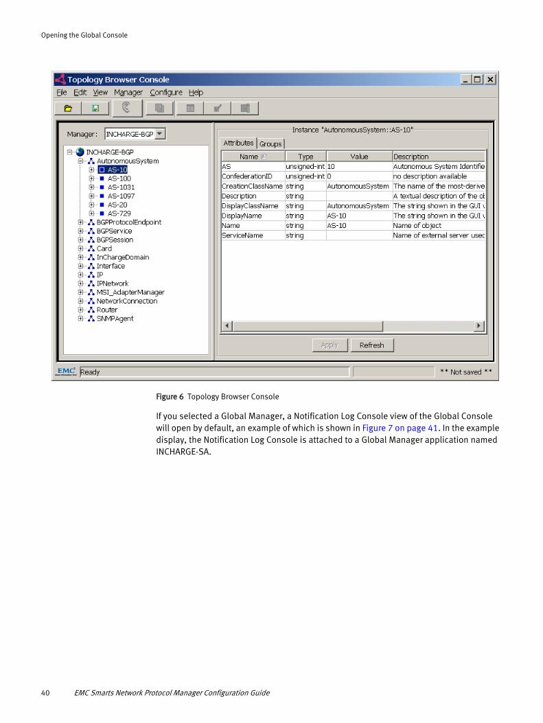
Opening the Global Console
Figure 6 Topology Browser Console
If you selected a Global Manager, a Notification Log Console view of the Global Console will open by default, an example of which is shown in Figure 7 on page 41. In the example display, the Notification Log Console is attached to a Global Manager application named INCHARGE-SA.
40 EMC Smarts Network Protocol Manager Configuration Guide

Opening the Global Console
Figure 7 Notification Log Console
The EMC Smarts Service Assurance Manager Operator Guide provides detailed instructions on using the Global Console.
Procedure for opening the Global Manager Administration Console
You can open a Global Manager Administration Console view from any Global Console that is attached to a Global Manager, such as the Notification Log Console in Figure 7 on page 41, by selecting the Configure > Global Manager Administration Console menu option. Figure 15 on page 62 is an example of a Global Manager Administration Console attached to a Global Manager named INCHARGE-SA.
Procedure for opening the Domain Manager Administration Console
You can open a Domain Manager Administration Console view from any Global Console that is attached to a Domain Manager, such as the Topology Browser Console in Figure 6 on page 40, by selecting the Configure > Domain Manager Administration Console menu option. Figure 8 on page 42 is an example of a Domain Manager Administration Console attached to a Domain Manager named INCHARGE-BGP.
Procedure for opening the Global Manager Administration Console 41
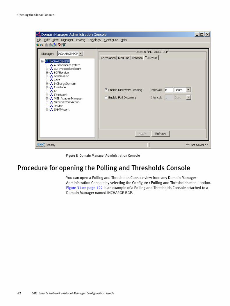
Opening the Global Console
Figure 8 Domain Manager Administration Console
Procedure for opening the Polling and Thresholds ConsoleYou can open a Polling and Thresholds Console view from any Domain Manager Administration Console by selecting the Configure > Polling and Thresholds menu option. Figure 31 on page 122 is an example of a Polling and Thresholds Console attached to a Domain Manager named INCHARGE-BGP.
42 EMC Smarts Network Protocol Manager Configuration Guide

CHAPTER 4Configuring IP Availability Manager
This chapter provides instructions for configuring an IP Availability Manager in a Network Protocol Manager deployment. It consists of the following sections:
◆ Configuration overview ........................................................................................... 44◆ Topology and CLI device-access object import ........................................................ 44◆ About the protocol topology collection sets ............................................................ 48◆ Tagged IP object import .......................................................................................... 48◆ CLI discovery, CLI polling, and CLI device-access groups ......................................... 49◆ Enabling protocol light discovery ............................................................................ 51◆ Enabling overlapping IP address discovery ............................................................. 51◆ Enabling interoperability with the VPN-Tagging Server............................................. 52◆ Creating CLI device-access groups .......................................................................... 53
Configuring IP Availability Manager 43
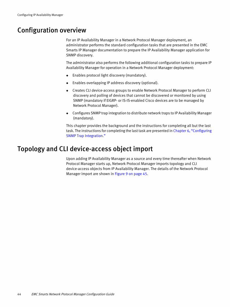
Configuring IP Availability Manager
Configuration overviewFor an IP Availability Manager in a Network Protocol Manager deployment, an administrator performs the standard configuration tasks that are presented in the EMC Smarts IP Manager documentation to prepare the IP Availability Manager application for SNMP discovery.
The administrator also performs the following additional configuration tasks to prepare IP Availability Manager for operation in a Network Protocol Manager deployment:
◆ Enables protocol light discovery (mandatory).
◆ Enables overlapping IP address discovery (optional).
◆ Creates CLI device-access groups to enable Network Protocol Manager to perform CLI discovery and polling of devices that cannot be discovered or monitored by using SNMP (mandatory if EIGRP- or IS-IS-enabled Cisco devices are to be managed by Network Protocol Manager).
◆ Configures SNMP trap integration to distribute network traps to IP Availability Manager (mandatory).
This chapter provides the background and the instructions for completing all but the last task. The instructions for completing the last task are presented in Chapter 6, “Configuring SNMP Trap Integration.”
Topology and CLI device-access object importUpon adding IP Availability Manager as a source and every time thereafter when Network Protocol Manager starts up, Network Protocol Manager imports topology and CLI device-access objects from IP Availability Manager. The details of the Network Protocol Manager import are shown in Figure 9 on page 45.
44 EMC Smarts Network Protocol Manager Configuration Guide

Configuring IP Availability Manager
Global Manager
IP Availability Manager
Subset ofNetworktopology
Subset of
Subset of
Subset ofNetwork Protocol Manager
for IS-IS
BGPtopology
collection set
OSPFtopology
collection set
EIGRPtopology
collection set
Securitysettingobjects
IS-IStopology
collection set
CLI device-access objects
Topology
Topology
Topology
CLI device-access objects
Network Protocol Manager
Topology
(Contains encryptedlogin credentials)
Network Protocol Managerfor EIGRP
Network Protocol Managerfor OSPF
Network Protocol Managerfor BGP
Figure 9 Importing topology and CLI device-access objects from IP Availability Manager
Import of topology
As indicated in Figure 9 on page 45, Network Protocol Manager imports only the objects that it is designed to manage. To accomplish that end, IP Availability Manager, when it is configured to do so, not only performs its traditional discovery of network objects, but also creates protocol topology collection sets from the discovered network objects.
Import of CLI device-access objects
Figure 9 on page 45 also shows that Network Protocol Manager imports CLI device-access objects from IP Availability Manager.
IP Availability Manager maintains these user-created CLI device-access objects, which are required by Network Protocol Manager for CLI discovery and CLI polling of devices that cannot be discovered or monitored by using SNMP. Instructions for creating CLI device-access objects are given in “Creating CLI device-access groups” on page 53.
Topology and CLI device-access object import 45
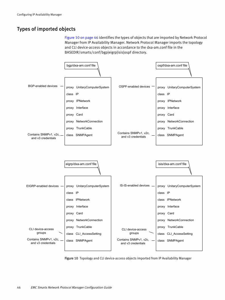
Configuring IP Availability Manager
Types of imported objects
Figure 10 on page 46 identifies the types of objects that are imported by Network Protocol Manager from IP Availability Manager. Network Protocol Manager imports the topology and CLI device-access objects in accordance to the dxa-am.conf file in the BASEDIR/smarts/conf/bgp|eigrp|isis|ospf directory.
bgp/dxa-am.conf file
proxy UnitaryComputerSystem
class IP
class IPNetwork
proxy Interface
proxy Card
proxy NetworkConnection
proxy TrunkCable
class CLI_AccessSetting
class SNMPAgent
eigrp/dxa-am.conf file
Contains SNMPv1, v2c,and v3 credentials
CLI device-accessgroups
EIGRP-enabled devices
proxy UnitaryComputerSystem
class IP
proxy IPNetwork
proxy Interface
proxy Card
proxy NetworkConnection
proxy TrunkCable
class SNMPAgent
ospf/dxa-am.conf file
Contains SNMPv1, v2c,and v3 credentials
OSPF-enabled devices
proxy UnitaryComputerSystem
class IP
class IPNetwork
proxy Interface
proxy Card
proxy NetworkConnection
proxy TrunkCable
class CLI_AccessSetting
class SNMPAgent
isis/dxa-am.conf file
Contains SNMPv1, v2c,and v3 credentials
CLI device-accessgroups
IS-IS-enabled devices
Contains SNMPv1, v2c,and v3 credentials
BGP-enabled devices proxy UnitaryComputerSystem
class IP
proxy IPNetwork
proxy Interface
proxy Card
proxy NetworkConnection
proxy TrunkCable
class SNMPAgent
Figure 10 Topology and CLI device-access objects imported from IP Availability Manager
46 EMC Smarts Network Protocol Manager Configuration Guide

Configuring IP Availability Manager
Through the UnitaryComputerSystem class in the dxa-am.conf file, Network Protocol Manager imports routing devices that are running BGP, EIGRP, IS-IS, or OSPF services. Those devices may be physical routers, virtual routers that are implemented within physical routers or switches, or the following types of router cards in switches:
◆ Route switch module (RSM)
◆ Route switch feature card (RSFC)
◆ Multilayer switch feature card (MSFC)
Through the UnitaryComputerSystem class in the dxa-am.conf file, Network Protocol Manager also imports switch devices that contain interface cards that are running BGP, EIGRP, IS-IS, or OSPF services.
UnitaryComputerSystem is the parent class of Router and Switch. Router is the parent class of MSFC, RSFC, and RSM.
IP Availability Manager discovers instances of the Router class and its subclasses, as well as instances of the Switch class. In turn, Network Protocol Manager imports the router and switch objects from IP Availability Manager, along with the network objects that are associated with the router and switch objects. Those network objects are identified in the dxa-am.conf file.
Also, for instances of the classes that are preceded with “proxy” in the dxa-am.conf file, Network Protocol Manager subscribes to routing-protocol-relevant status updates for those instances from IP Availability Manager. Table 7 on page 47 describes “proxy” and the other data exchange adapter (DXA) commands that are included in the dxa-am.conf file.
Table 7 Partial list of DXA configuration commands (page 1 of 2)
Keyword Value Description
class <remote class name> [<local class name>]Example: class IP
Identifies a class and the start of a class block that ends one line before another class block begins. A class block represents instances of a particular class and its subclasses, and contains all interested properties of those instances.
proxy <remote class name> [<local class name>]Example: proxy UnitaryComputerSystem
Same as “class” with the following additional behavior: For the specified class, all instances of the remote class will be instrumented locally. That is, the local server will continuously monitor the instrumented attributes or events of the class instances on the remote server, and reflect changes in the local objects as changes occur in the remote objects.
attr <remote attribute name> [<local attribute name>]Example: class IP attr DisplayName
Identifies the class attributes that are to be imported from the remote server.
rel <remote relationship name> [<local relationship name>]Example: class IP rel Underlying
Identifies the class relationships that are to be imported from the remote server.
Topology and CLI device-access object import 47

Configuring IP Availability Manager
About the protocol topology collection setsWhen the DisableProtocolDiscovery parameter in IP Availability Manager’s tpmgr-param.conf file is set to FALSE, IP Availability Manager not only performs its traditional discovery of network objects, but it also creates BGP-, EIGRP-, IS-IS-, and OSPF-relevant topology collection sets from the discovered network objects. By default, it queries the SNMP agent of every device in the managed network for routing-protocol support.
The protocol light discovery feature is described in the EMC Smarts IP Manager documentation.
Tagged IP object importNetwork Protocol Manager for BGP and Network Protocol Manager for OSPF are able to understand and store tagged IP objects that are imported from IP Availability Manager. Tagged IP objects enable a Domain Manager to include overlapping IP addresses in its modeled topology.
The inclusion of overlapping IP addresses in the modeled topology results in a more accurate and more complete model of the topology, which enables IP Availability Manager, Network Protocol Manager for BGP, and Network Protocol Manager for OSPF to perform more accurate correlation analysis.
ignoreclass <subclass name>Example: class IP ignoreclass DuplicateIP
Stops the import of instances of the specified subclass from the remote server.
in <container class name> <relation name> [<instance name>]Example: class UnitaryComputerSystem in TopologyCollection ConsistsOf EIGRP-System
Directs the local server to import instances that are related to a remote container-type class.The example directs the local server to import only those device instances that are members of the EIGRP-System ConsistsOf relationship.
probe <element type>Example: class SNMPAgent probe EIGRP
Enables postprocessing scripts to be invoked from the local server whenever a new instance of the given class, with the specified element type, is created on the remote server.
conditionalprobe <element type> <method> <remote attribute value> <same local attribute value>Example: class SNMPAgent conditionalprobe EIGRP getSystem DiscoveredLastAt DiscoveredLastAt
Behaves the same as “probe” when a new instance of the given class, with the specified element type, is created on the remote server.In addition, for an existing instance, “conditionalprobe” compares the value of the specified attribute in the remote instance to the same attribute in the local instance. If the value has changed in the remote instance, the probe takes place even though this instance is not new.
Table 7 Partial list of DXA configuration commands (page 2 of 2)
Keyword Value Description
48 EMC Smarts Network Protocol Manager Configuration Guide
Configuring IP Availability Manager
Overlapping IP addresses
In a networked environment, the same IP addresses can be reused and configured across multiple systems (devices) that are running in separate networks. These IP addresses, known as overlapping IP addresses, are prominent in (1) Multiprotocol Label Switching (MPLS) VPN environments and (2) networks that are centrally managed by Managed Service Providers, where private IP networks of customers often deploy identically numbered IP address spaces.
IP tagging feature
The IP tagging feature, which was introduced in IP Manager 7.0, enables IP Availability Manager to discover and create IP objects for both VPN Routing and Forwarding (VRF) and non-VRF overlapping IP addresses, where a non-VRF overlapping IP address is defined as an overlapping IP address that is not part of an MPLS VPN.
Network Protocol Manager for BGP and Network Protocol Manager for OSPF are able to understand VRF and non-VRF IP objects that have been tagged by IP Availability Manager.
IP Availability Manager also creates a corresponding IPNetwork object and tags it with the same value that is used to tag the IP object. And, for both tagged IP and IPNetwork objects, IP Availability Manager sets the object’s Tag attribute to the tag value that is used to tag the object.
The Route Distinguisher (RD) IP tagging policy is used in versions 8.1.x and 9.x of the IP Manager. These features are described in the EMC Smarts IP Manager documentation.
VPN-Tagging Server
The VPN-Tagging Server enables IP Availability Manager to correctly represent in its modeled topology certain VRF overlapping IP-address configurations. When the VPN-Tagging Server discovers these configurations, it sends the connection information to IP Availability Manager so that IP Availability Manager can distinguish the overlapping IP addresses in the configurations. Doing so enables IP Availability Manager to create the correct network connections for the configurations.
Creating the correct network connections means that Network Protocol Manager for BGP and Network Protocol Manager for OSPF will import more accurate topology information from IP Availability Manager.
CLI discovery, CLI polling, and CLI device-access groupsNetwork Protocol Manager performs CLI discovery and CLI polling to discover and monitor devices that cannot be discovered or monitored by using SNMP. As shown in Figure 11 on page 50, CLI discovery and CLI polling are controlled by CLI device-access objects that are created on the IP Availability Manager, through the Polling and Thresholds Console, and then imported by Network Protocol Manager.
CLI discovery, CLI polling, and CLI device-access groups 49

Configuring IP Availability Manager
Managed network
IS-IS-enabledCisco devices
Network Protocol ManagerFor ISIS
SNMP discovery & polling CLI discovery CLI polling
EIGRP-enabledCisco devices
CLI deviceaccess objects
(Configure CLIdevice-access groups)
Polling and ThresholdsConsole
IP Availability Manager
Network Protocol Managerfor EIGRP
CLI discoveryCLI polling
OSPF Discovery (OSPFPassive Interface
Detection)
BGP Manager (RouteReflector Discovery)
CLI discovery
CLI discovery
Figure 11 CLI discovery, CLI polling, and CLI device-access object creation and transfer
The execution of CLI discovery and CLI polling requires login credentials, which are used by Network Protocol Manager to access the Network Protocol-enabled devices and to invoke CLI commands from the devices. The CLI device-access objects carry the login credential information.
Instructions for creating CLI device access objects for Network Protocol Manager are given in “Creating CLI device-access groups” on page 53.
50 EMC Smarts Network Protocol Manager Configuration Guide

Configuring IP Availability Manager
Enabling protocol light discoveryBy default, IP Availability Manager is not enabled to perform protocol light discovery. To enable this feature, set the DisableProtocolDiscovery parameter in IP Availability Manager’s tpmgr-param.conf file to FALSE.
To enable protocol light discovery:
1. Go to the BASEDIR/smarts/bin directory in the IP Manager installation area and type the following command to open the tpmgr-param.conf file:
sm_edit conf/discovery/tpmgr-param.conf
Press Enter.
2. Set the following parameter to FALSE:
DisableProtocolDiscovery FALSE
3. Save and close the file.
The modified version of the tpmgr-param.conf file is saved to the BASEDIR/smarts/local/conf/discovery directory.
4. If IP Availability Manager was running before you edited the tpmgr-param.conf file, type the following command from BASEDIR/smarts/bin to make your change take effect:
sm_tpmgr -s <IP Availability Manager instance name> --load-conf=tpmgr-param.conf
Press Enter.
Enabling overlapping IP address discovery
This procedure is not applicable for IP Availability Manager versions 8.1.x and higher. The VPNIP attribute has been deprecated in release 8.1.x and 9.x. Refer to the Route Distinguisher (RD) IP tagging policy configuration procedures in the EMC Smarts IP Manager Concepts Guide.
By default, IP Availability Manager releases prior to version 8.1.x are not enabled to perform overlapping IP address discovery. To enable this feature, set the following parameters in IP Availability Manager’s tpmgr-param.conf file to the shown values:
DisableOverlappingIP FALSEUseVPNIP FALSEEnableShadowIP TRUE (default)
To enable overlapping IP discovery:
1. Go to the BASEDIR/smarts/bin directory in the IP Manager installation area and type the following command to open the tpmgr-param.conf file:
sm_edit conf/discovery/tpmgr-param.conf
Press Enter.
Enabling protocol light discovery 51

Configuring IP Availability Manager
2. Set the following three parameters to the values shown:
DisableOverlappingIP FALSEUseVPNIP FALSEEnableShadowIP TRUE
3. Save and close the file.
The modified version of the tpmgr-param.conf file is saved to the BASEDIR/smarts/local/conf/discovery directory.
4. If IP Availability Manager was running before you edited the tpmgr-param.conf file, type the following command from BASEDIR/smarts/bin to make your change take effect:
sm_tpmgr -s <IP Availability Manager instance name> --load-conf=tpmgr-param.conf
Press Enter.
Enabling interoperability with the VPN-Tagging ServerTo enhance overlapping IP address discovery, you, as an administrator, enable IP Availability Manager to interoperate with the VPN-Tagging Server.
Assuming that the DisableOverlappingIP, UseVPNIP, and EnableShadowIP parameters in the tpmgr-param.conf file are set as specified in the previous section, you do so by setting the following parameter in IP Availability Manager’s discovery.conf file to TRUE:
importExternalTagsConnections TRUE
In addition, you need to enable the VPN-Tagging Server to interoperate with IP Availability Manager. You do so by adding IP Availability Manager as a source to the VPN-Tagging Server.
To enable interoperability between IP Availability Manager and the VPN-Tagging Server:
1. Consult the EMC Smarts IP Manager documentation and follow the instructions to set the following parameter in the discovery.conf file to the value shown:
importExternalTagsConnections TRUE
2. Consult the EMC Smarts IP Manager Concepts Guide and follow the instructions to add IP Availability Manager as a source to the VPN-Tagging Server.
The VPN-Tagging Server performs overlapping-IP and corresponding network-connection discovery in two vendor-specific environments: Cisco and Alcatel-Lucent. To complete the configuration of the VPN-Tagging Server, open the BASEDIR/smarts/conf/vpn-tagging/vpn-tagging.conf file (in the Network Protocol Manager installation area) and perform the following additional tasks:
◆ Mandatory and for Alcatel-Lucent only: Add the Enable5620SAMDiscovery parameter with a value of TRUE to the vpn-tagging.conf file.
◆ Optional and for Alcatel-Lucent only: Modify the default values of the AlcatelDiscoveryInterval parameter.
◆ Optional and for Cisco only: Modify the default values of the DiscoveryFilter parameter.
52 EMC Smarts Network Protocol Manager Configuration Guide

Configuring IP Availability Manager
Creating CLI device-access groupsBecause IP Availability Manager is a component of many EMC Smarts deployments, IP Availability Manager has been selected as the central repository for specifying and storing device-access credentials, such as the login credentials that are required by Network Protocol Manager to perform CLI discovery and CLI polling.
When Network Protocol Manager adds IP Availability Manager as a source, Network Protocol Manager imports the device-access credentials from IP Availability Manager and makes the credentials available to the CLI discovery driver and the CLI poller.
You, as an administrator, use the Polling and Thresholds Console to specify sets of device-access credentials in the form of CLI device-access groups. Each CLI device-access group contains:
◆ An access-protocol method: Telnet, SSH1, or SSH2; Telnet, by default.
◆ A set of device-access credentials: a username, a user password, and a privileged-mode enable password.
◆ A set of member devices for which the access method and device-access credentials apply.
Attach the Polling and Thresholds Console
Upon attaching the Polling and Thresholds Console to IP Availability Manager, you use the Device Access tab, the CLI Access Group, and the CLI Access Setting on the Polling and Thresholds Console to specify the CLI device-access groups.
If your Network Protocol Manager deployment contains multiple IP Availability Managers, proceed as follows:
1. Choose one of those IP Availability Managers as the target IP Availability Manager.
2. Attach the Polling and Thresholds Console to the target IP Availability Manager and create all the CLI device-access groups for the deployment on that one server.
Creating CLI device-access groups on different IP Availability Managers can lead to matching-criteria priority conflicts between the groups.
Create CLI device-access groups
You create a CLI device-access group for each group of managed devices that is configured with a different access protocol and/or different set of CLI login credentials. The assumption is that all devices that use a particular access protocol are configured with the same set of credentials (and timeout value). If there are two groups of devices that use a particular access protocol, each configured with its own set of credentials, you would create two CLI device-access groups for that particular access protocol. For example, you would create two CLI device-access groups named SSH2_S1 and SSH2_S2. The matching criteria for each of the groups would limit the group’s members to the appropriate devices.
Creating CLI device-access groups 53

Configuring IP Availability Manager
Table 8 Default values for the CLI Access Setting
Parameter Default value Description
AccessProtocol TELNET SSH1 SSH2Default: TELNET
Determines the remote-access application to use to establish connections to the managed devices that belong to this group. Secure Shell 2 (SSH2) is recommended.The Network Protocol Manager includes Telnet client software, and for installations on Windows systems, also includes SSH client software.Instructions for configuring an SSH client are given in Chapter 8, “Configuring SSH Security.”
LoginID String of unspecified lengthDefault: null string (empty)
Specifies the username (user ID) for the managed devices that belong to this group.You must enter a value for this parameter.
Password A structure that has the following default value:{NULL String,ENCRYPTED}
Specifies the user password for the managed devices that belong to this group.If the managed devices that belong to this group are configured for passwordless authentication, or if the access protocol for this group is SSH1 or SSH2 and passwordless authentication is in effect, leave this parameter blank. Otherwise, enter the password twice to confirm the password value.
Note: IP Availability Manager uses the site key to encrypt the entered password value. As explained in EMC Smarts System Administration Guide, the site key is created during the installation of EMC Smarts applications.
PrivilegedModePassword A structure that has the following default value:{NULL String,ENCRYPTED}
Specifies the Privileged-mode enable password for the managed devices that belong to this group.For Privileged-mode access (not User-mode access), and assuming that the ProhibitPrivLevelCLILogon parameter in the eigrp.conf file (Table 3 on page 30) or the isis.conf file (Table 4 on page 31) is FALSE (default), you must enter a value for this parameter. Enter the password twice to confirm the password value.
Note: IP Availability Manager uses the site key to encrypt the entered password value. As explained in EMC Smarts System Administration Guide, the site key is created during the installation of EMC Smarts applications.
Timeout 1 to 496 secondsDefault: 10 seconds
Sets the amount of time to wait for a Telnet/SSH response before the Telnet /SSH session request times out.
54 EMC Smarts Network Protocol Manager Configuration Guide

Configuring IP Availability Manager
Synchronize CLI credentials between IP and NPM
When you finish editing the properties of CLI device-access groups, follow these procedures in IP Availability Manager to ensure changes in CLI credentials are synchronized with your Network Protocol Manager servers.
1. Click the Apply button to save the configuration changes to an existing group object or to a newly created group object in the repository of IP Availability Manager.
2. Click the Reconfigure toolbar button (described in Table 11 on page 113) to make the configuration changes take effect.
3. Rediscover those devices affected by the change in credentials.
When the IP discovery process completes, the Network Protocol Manager discovery process automatically starts. Network Protocol Manager imports the group object and saves the group object to its repository.
Network Protocol Manager synchronizes its CLI-device-access group and group-related objects with the CLI-device-access group and group-related objects on IP Availability Manager.
There may be an 8-minute delay before the credentials are synchronized between the IP and NPM servers.
Creating CLI device-access groups 55

Configuring IP Availability Manager
56 EMC Smarts Network Protocol Manager Configuration Guide

CHAPTER 5Configuring the Global Manager
This chapter provides instructions for configuring the Global Manager in a Network Protocol Manager deployment. It consists of the following sections:
◆ Configuration overview ........................................................................................... 58◆ About the Global Manager ...................................................................................... 58◆ IC Domain Configuration objects ............................................................................. 61◆ Loading the XML configuration file for Network Protocol Manager............................ 64◆ Specifying the underlying domains ......................................................................... 65◆ Enabling the display of BGP, EIGRP, IS-IS, and OSPF topology maps........................ 75
Configuring the Global Manager 57
Configuring the Global Manager
Configuration overviewFor the Global Manager to import topology and events from the underlying components in a Network Protocol Manager deployment, you must configure the Global Manager with the proper data exchange adapter (DXA) files. The Global Manager integrates and correlates the imported topology and events, and relates the data to services and customers.
You use the Global Console to configure the DXA files. The EMC Smarts Service Assurance Manager Configuration Guide provides detailed instructions on using the Global Console to complete Global Manager configurations.
The Global Manager and Global Console are part of the EMC Smarts Service Assurance Manager.
About the Global ManagerMost of the configuration tasks for configuring the Global Manager in a Network Protocol Manager deployment are accomplished by using the Global Manager Administration Console view of the Global Console. Figure 12 on page 59 summarizes the Global Manager Administration Console interaction with the Global Manager.
58 EMC Smarts Network Protocol Manager Configuration Guide

Configuring the Global Manager
+
+
+
+
-
Escalation Policies
Notification Lists
Tools
User Profiles
Users
ICS Configuration
System Defaults
Business Templates
IC Domain Configuration
Domains
Domain Groups
Domain Tags
Domain Types
Global Manager
Repository
Objects
export(call)
XMLstream
XMLstream
Global Console
Global Manager Administration Console
At consolestartup
Userconfigurations
XML-to-GUIconversion
GUI-to-XMLconversion
+
+
+
+
+
+
+
+
-
-
INCHARGE-SA-
+
+
+
+
-
Click object
Click Apply
ICS Configurations in the
ics-default.xml file
Get config objects
objectsto
XML
Confighandlers
XMLto
objects
export(call)
= object
Configobjects
Yes
At Global Manager startup
Anyrepository file
?
No
Yes
Load ics-default.xml file
No Loadrepository
file
--norestorein startup line
?
Figure 12 Global Manager Administration Console interaction with the Global Manager
As shown in Figure 12, the initial configurations for the Global Manager are stored in the ics-default.xml file and imported into the Global Manager’s repository when the Global Manager starts up. The configurations displayed in a newly started Global Manager Administration Console are exported from the Global Manager’s repository.
Figure 13 on page 60 shows the relationships between Domain Group, Domain, Domain Type, and Domain Tag configuration objects. The intent of the Domain Group is to represent the server components of a split-server Domain Manager as a single entity. Doing so makes a split-server Domain Manager look just like a standalone Domain Manager to administrators and users.
About the Global Manager 59
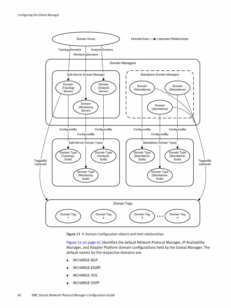
Configuring the Global Manager
Domain Group
TaggedBy(optional)
Domain Tags
Domain Tag3
Domain Tagn
Domain Tag2
Domain Tag1
Domain Type(Standalone-
Suite)
Domain Type(Standalone-
Suite)
Domain Type(Standalone-
Suite)
Domain Type(Topology-
Suite)
Domain Type(Analysis-
Suite)
Domain Type(Monitoring-
Suite)
Domain Managers
Standalone Domain Managers
Domain(Standalone)
Domain(Standalone)
Domain(Standalone)
Domain(Monitoring
Server)
Domain(Topology
Server)
Domain(AnalysisServer)
TopologyDomains
MonitoringDomains
AnalysisDomains
Split-Server Domain Manager
ConfiguredBy
ConfiguredBy
ConfiguredBy
Split-Server Domain Types
ConfiguredBy
ConfiguredBy
ConfiguredBy
Standalone Domain Types
TaggedBy(optional)
...
Directed lines ( ) represent Relationships
Figure 13 IC Domain Configuration objects and their relationships
Figure 14 on page 61 identifies the default Network Protocol Manager, IP Availability Manager, and Adapter Platform domain configurations held by the Global Manager. The default names for the respective domains are:
◆ INCHARGE-BGP
◆ INCHARGE-EIGRP
◆ INCHARGE-ISIS
◆ INCHARGE-OSPF
60 EMC Smarts Network Protocol Manager Configuration Guide

Configuring the Global Manager
◆ INCHARGE-AM
◆ INCHARGE-OI
Each of these domain names represents a standalone Domain Manager.
Domains
ConfiguredBy
INCHARGE-OI
INCHARGE-OI-SUITE
ConfiguredBy
INCHARGE-AM
INCHARGE-AM-SUITE
ConfiguredBy
INCHARGE-OSPF
INCHARGE-OSPF-SUITE
ConfiguredBy
INCHARGE-ISIS
INCHARGE-ISIS-SUITE
ConfiguredBy
INCHARGE-EIGRP
Domain Types
INCHARGE-EIGRP-SUITE
ConfiguredBy
INCHARGE-BGP
INCHARGE-BGP-SUITE
Directed lines ( ) represent Relationships
Figure 14 Default domain configurations for a Network Protocol Manager deployment
IC Domain Configuration objectsFigure 15 on page 62 presents an example display of a Global Manager Administration Console attached to a Global Manager named INCHARGE-SA.
IC Domain Configuration objects 61

Configuring the Global Manager
IC DomainConfigurations
Toobar buttons for launchingIC Domain Configuration wizards
Toobar button for launchingServer Reconfiguration
Figure 15 Global Manager and Administration Console
Listed at the bottom of the configuration tree of the Global Manager Administration Console are the four categories of IC Domain Configuration objects: Domains, Domain Groups, Domain Tags, and Domain Types. Listed under each category are instances of these objects; for example, the default domain “INCHARGE-AM” is listed under Domains. Selecting an object in the left panel displays its attributes and their values in the right panel.
IC Domain Configuration creation wizards
Each IC Domain Configuration category has an associated creation wizard to simplify how to specify its configuration objects. You launch an IC Domain Configuration wizard in one of three ways:
◆ By clicking one of the four wizard toolbar buttons that are identified in Figure 15 on page 62
◆ By right-clicking an IC Domain Configuration category name (for example, right-clicking Domains) and then clicking the pop-up menu
◆ By selecting New Domain, New Domain Group, New Domain Type, or New Domain Tag from the Edit menu
When you create a domain, the created domain is enabled automatically.
62 EMC Smarts Network Protocol Manager Configuration Guide

Configuring the Global Manager
IC Domain Configuration server reconfiguration
Clicking the Apply button, which is available to all configuration categories, writes configuration changes to the Global Manager’s repository. Clicking the Reconfigure button, which is available only to the IC Domain Configuration categories, calls a “reconfigure” method that determines which underlying domains need to be synchronized or resynchronized (that is, determines from which underlying domains topology or events need to be imported or reimported) and then initiates the needed data transfers. Calling the reconfigure method is referred to as “reconfiguring the Global Manager.”
In addition to clicking the Reconfigure button, the reconfigure method can be initiated in two other ways: by clicking the Reconfigure toolbar button that is identified in Figure 15 on page 62, or by selecting Reconfigure Server from the Configure menu.
Figure 16 on page 63 demonstrates how reconfiguring the Global Manager works.
Topology and Events
Global Manager
Compare
InCharge Domain Group and Domain Objects
InChargeDomainGroup Objects InChargeDomain Objects
IC Domain Configuration Objects
Changes
Domain Tag Configuration Objects Domain Type Configuration Objects
Domain Group Configuration Objects Domain Configuration Objects
Domain Managers
Standalone Domain Manager Split-Server Analysis Server
Split-Server Topology Server Split-Server Monitoring Server
Available only if differences exist between IC Domain Configuration objects and InCharge Domain Group and Domain objects
Click Reconfigure
Domain group or domain configuration object was
deleted or disabled.
Response:
Delete domain group or domain object
Domain group, domain, domain type, or domain tag
configuration object’s attributes have changed.
Response:
Change domain group or domain object’s attributes
Domain group or domain configuration object was
created or enabled.
Response:
Create domain group or domain object
Figure 16 How reconfiguring the Global Manager works
IC Domain Configuration objects 63
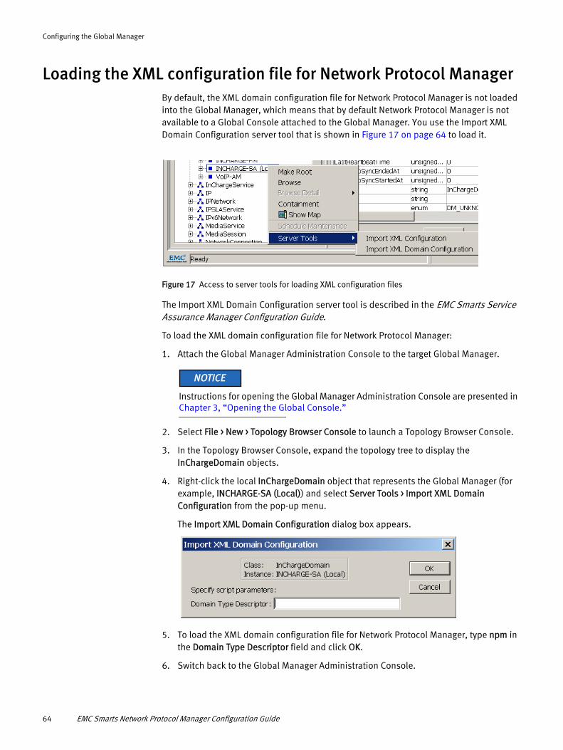
Configuring the Global Manager
Loading the XML configuration file for Network Protocol ManagerBy default, the XML domain configuration file for Network Protocol Manager is not loaded into the Global Manager, which means that by default Network Protocol Manager is not available to a Global Console attached to the Global Manager. You use the Import XML Domain Configuration server tool that is shown in Figure 17 on page 64 to load it.
Figure 17 Access to server tools for loading XML configuration files
The Import XML Domain Configuration server tool is described in the EMC Smarts Service Assurance Manager Configuration Guide.
To load the XML domain configuration file for Network Protocol Manager:
1. Attach the Global Manager Administration Console to the target Global Manager.
Instructions for opening the Global Manager Administration Console are presented in Chapter 3, “Opening the Global Console.”
2. Select File > New > Topology Browser Console to launch a Topology Browser Console.
3. In the Topology Browser Console, expand the topology tree to display the InChargeDomain objects.
4. Right-click the local InChargeDomain object that represents the Global Manager (for example, INCHARGE-SA (Local)) and select Server Tools > Import XML Domain Configuration from the pop-up menu.
The Import XML Domain Configuration dialog box appears.
5. To load the XML domain configuration file for Network Protocol Manager, type npm in the Domain Type Descriptor field and click OK.
6. Switch back to the Global Manager Administration Console.
64 EMC Smarts Network Protocol Manager Configuration Guide

Configuring the Global Manager
7. In the left panel of the Global Manager Administration Console, expand the configuration tree to display the Domains.
The Network Protocol Manager domains appear in the Domains list as INCHARGE-BGP, INCHARGE-EIGRP, INCHARGE-ISIS, and INCHARGE-OSPF. Because the names appears as gray text, the domains are disabled.
8. Continue with the procedures in “Specifying the underlying domains” on page 65.
Specifying the underlying domainsAn administrator uses the IC Domain Configuration objects to specify the underlying Network Protocol Manager, IP Availability Manager, and Adapter Platform domains in a Network Protocol Manager deployment. Doing so provides the sources of topology and events for the Global Manager and associates each underlying domain with the proper DXA file.
The expectation is that a user will either accept the default Network Protocol Manager domains named INCHARGE-BGP, INCHARGE-EIGRP, INCHARGE-ISIS, and INCHARGE-OSPF, or make copies of the default domains to create new domains that have a different name. For example, you can make a copy of INCHARGE-BGP and name it ASIA-INCHARGE-BGP.
This section provides procedures for the following two configuration scenarios:
◆ Configuration scenario 1: A Network Protocol Manager deployment that contains:
• A Network Protocol Manager for BGP named INCHARGE-BGP
• A Network Protocol Manager for EIGRP named INCHARGE-EIGRP
• A Network Protocol Manager for IS-IS named INCHARGE-ISIS
• A Network Protocol Manager for OSPF named INCHARGE-OSPF
• An IP Availability Manager named INCHARGE-AM
• An Adapter Platform named INCHARGE-OI
Specifying the underlying domains 65
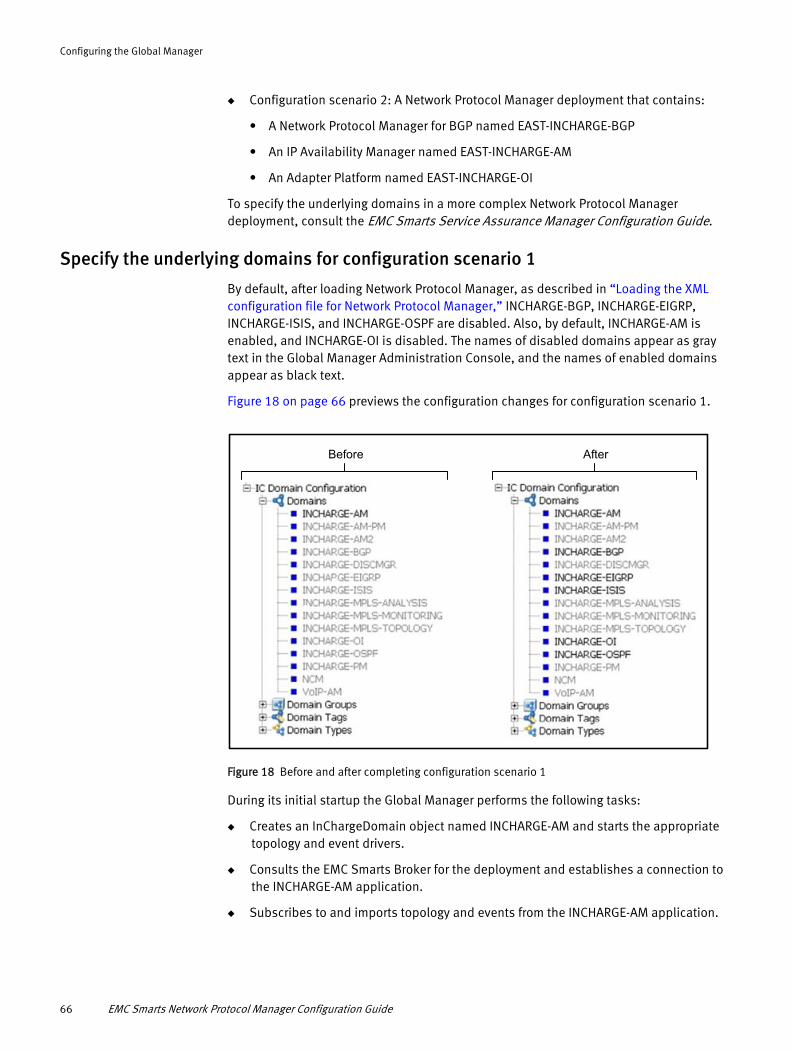
Configuring the Global Manager
◆ Configuration scenario 2: A Network Protocol Manager deployment that contains:
• A Network Protocol Manager for BGP named EAST-INCHARGE-BGP
• An IP Availability Manager named EAST-INCHARGE-AM
• An Adapter Platform named EAST-INCHARGE-OI
To specify the underlying domains in a more complex Network Protocol Manager deployment, consult the EMC Smarts Service Assurance Manager Configuration Guide.
Specify the underlying domains for configuration scenario 1
By default, after loading Network Protocol Manager, as described in “Loading the XML configuration file for Network Protocol Manager,” INCHARGE-BGP, INCHARGE-EIGRP, INCHARGE-ISIS, and INCHARGE-OSPF are disabled. Also, by default, INCHARGE-AM is enabled, and INCHARGE-OI is disabled. The names of disabled domains appear as gray text in the Global Manager Administration Console, and the names of enabled domains appear as black text.
Figure 18 on page 66 previews the configuration changes for configuration scenario 1.
Before After
Figure 18 Before and after completing configuration scenario 1
During its initial startup the Global Manager performs the following tasks:
◆ Creates an InChargeDomain object named INCHARGE-AM and starts the appropriate topology and event drivers.
◆ Consults the EMC Smarts Broker for the deployment and establishes a connection to the INCHARGE-AM application.
◆ Subscribes to and imports topology and events from the INCHARGE-AM application.
66 EMC Smarts Network Protocol Manager Configuration Guide

Configuring the Global Manager
Every time that the Global Manager is restarted, it automatically initiates a server reconfiguration (that is, calls the reconfigure method) to align the IC domain and domain group configuration objects with the InCharge domain and domain group objects. Because the only IC Domain Configuration object enabled at the initial startup is INCHARGE-AM, the only alignment that is required is the one just described.
If the synchronization with the INCHARGE-AM application fails, or if no IP Availability Manager application named INCHARGE-AM exists in the deployment, the Global Manager writes an error message to its log file.
This section consists of the following procedures:
◆ “Procedure for specifying the underlying INCHARGE-BGP domain for configuration scenario 1”
◆ “Procedure for specifying the underlying INCHARGE-EIGRP domain for configuration scenario 1”
◆ “Procedure for specifying the underlying INCHARGE-ISIS domain for configuration scenario 1”
◆ “Procedure for specifying the underlying INCHARGE-OSPF domain for configuration scenario 1”
◆ “Procedure for specifying the underlying INCHARGE-OI domain for configuration scenario 1”
◆ “Procedure for reconfiguring the Global Manager for configuration scenario 1”
Procedure for specifying the underlying INCHARGE-BGP domain for configuration scenario 1To specify the underlying INCHARGE-BGP domain for configuration scenario 1:
1. Attach the Global Manager Administration Console to the target Global Manager.
Instructions for opening the Global Manager Administration Console are presented in Chapter 3, “Opening the Global Console.”
2. In the left panel of the Global Manager Administration Console, expand the configuration tree to display the Domains objects.
3. Select INCHARGE-BGP to display its configuration window.
4. In the configuration window, click the Enabled checkbox.
5. In the configuration window, click Apply to save your configuration changes.
6. In the Server Reconfiguration information dialog box that appears, click OK.
Procedure for specifying the underlying INCHARGE-EIGRP domain for configuration scenario 1To specify the underlying INCHARGE-EIGRP domain for configuration scenario 1:
1. In the left panel of the Global Manager Administration Console, expand the configuration tree to display the Domains objects.
2. Select INCHARGE-EIGRP to display its configuration window.
3. In the configuration window, click the Enabled checkbox.
Specifying the underlying domains 67

Configuring the Global Manager
4. In the configuration window, click Apply to save your configuration changes.
5. In the Server Reconfiguration information dialog box that appears, click OK.
Procedure for specifying the underlying INCHARGE-ISIS domain for configuration scenario 1To specify the underlying INCHARGE-ISIS domain for configuration scenario 1:
1. In the left panel of the Global Manager Administration Console, expand the configuration tree to display the Domains objects.
2. Select INCHARGE-ISIS to display its configuration window.
3. In the configuration window, click the Enabled checkbox.
4. In the configuration window, click Apply to save your configuration changes.
5. In the Server Reconfiguration information dialog box that appears, click OK.
Procedure for specifying the underlying INCHARGE-OSPF domain for configuration scenario 1To specify the underlying INCHARGE-OSPF domain for configuration scenario 1:
1. In the left panel of the Global Manager Administration Console, expand the configuration tree to display the Domains objects.
2. Select INCHARGE-OSPF to display its configuration window.
3. In the configuration window, click the Enabled checkbox.
4. In the configuration window, click Apply to save your configuration changes.
5. In the Server Reconfiguration information dialog box that appears, click OK.
Procedure for specifying the underlying INCHARGE-OI domain for configuration scenario 1To specify the underlying INCHARGE-OI domain for configuration scenario 1:
1. In the left panel of the Global Manager Administration Console, expand the configuration tree to display the Domains objects.
2. Select INCHARGE-OI to display its configuration window.
3. In the configuration window, click the Enabled checkbox.
4. In the configuration window, click Apply to save your configuration changes.
5. In the Server Reconfiguration information dialog box that appears, click OK.
Procedure for reconfiguring the Global Manager for configuration scenario 1To reconfigure the Global Manager for configuration scenario 1:
1. In the toolbar area of the Global Manager Administration Console, click the Reconfigure toolbar button.
2. In the Server Reconfiguration confirmation dialog box that appears, click Yes.
3. In the Server Reconfiguration information dialog box that appears, click Close.
In response, the Global Manager:
◆ Creates an InChargeDomain object named INCHARGE-BGP and starts the appropriate topology and event drivers.
68 EMC Smarts Network Protocol Manager Configuration Guide
Configuring the Global Manager
◆ Creates an InChargeDomain object named INCHARGE-EIGRP and starts the appropriate topology and event drivers.
◆ Creates an InChargeDomain object named INCHARGE-ISIS and starts the appropriate topology and event drivers.
◆ Creates an InChargeDomain object named INCHARGE-OSPF and starts the appropriate topology and event drivers.
◆ Creates an InChargeDomain object named INCHARGE-OI and starts the appropriate notification drivers.
◆ Consults the EMC Smarts Broker for the deployment and establishes a connection to the INCHARGE-BGP, INCHARGE-EIGRP, INCHARGE-ISIS, INCHARGE-OSPF, and INCHARGE-OI domains.
◆ Subscribes to and imports topology and events from the INCHARGE-BGP, INCHARGE-EIGRP, INCHARGE-ISIS, INCHARGE-OSPF domains.
◆ Subscribes to and imports notifications from the INCHARGE-OI domain.
The Global Manager will establish an additional connection to the INCHARGE-BGP, INCHARGE-EIGRP, INCHARGE-ISIS, or INCHARGE-OSPF domain under any of the following circumstances:
◆ To obtain the latest object attribute values for display in the Details tab of a routing-protocol Notification Properties dialog box.
◆ To obtain the latest object attribute values for display in a routing-protocol Containment dialog box.
Specifying the underlying domains 69
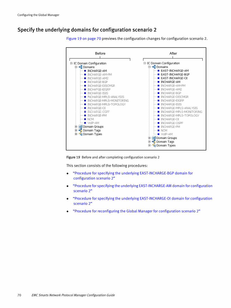
Configuring the Global Manager
Specify the underlying domains for configuration scenario 2
Figure 19 on page 70 previews the configuration changes for configuration scenario 2.
Before After
Figure 19 Before and after completing configuration scenario 2
This section consists of the following procedures:
◆ “Procedure for specifying the underlying EAST-INCHARGE-BGP domain for configuration scenario 2”
◆ “Procedure for specifying the underlying EAST-INCHARGE-AM domain for configuration scenario 2”
◆ “Procedure for specifying the underlying EAST-INCHARGE-OI domain for configuration scenario 2”
◆ “Procedure for reconfiguring the Global Manager for configuration scenario 2”
70 EMC Smarts Network Protocol Manager Configuration Guide

Configuring the Global Manager
Procedure for specifying the underlying EAST-INCHARGE-BGP domain for configuration scenario 2To specify the underlying EAST-INCHARGE-BGP domain for configuration scenario 2:
1. Attach the Global Manager Administration Console to the target Global Manager.
Instructions for opening the Global Manager Administration Console are presented in Chapter 3, “Opening the Global Console.”
2. In the left panel of the Global Manager Administration Console, right-click Domains and then click the pop-up menu to launch the Domain Creation Wizard.
3. Consult Figure 20 on page 72 and follow the directions to create a Network Protocol Manager domain named EAST-INCHARGE-BGP.
Procedure for specifying the underlying EAST-INCHARGE-AM domain for configuration scenario 2To specify the underlying EAST-INCHARGE-AM domain for configuration scenario 2:
1. In the left panel of the Global Manager Administration Console, right-click Domains and then click the pop-up menu to launch the Domain Creation Wizard.
2. Consult Figure 21 on page 73 and follow the directions to create an IP Availability Manager domain named EAST-INCHARGE-AM.
Procedure for specifying the underlying EAST-INCHARGE-OI domain for configuration scenario 2To specify the underlying EAST-INCHARGE-OI domain for configuration scenario 2:
1. In the left panel of the Global Manager Administration Console, right-click Domains and then click the pop-up menu to launch the Domain Creation Wizard.
2. In the Domain Creation Wizard, select INCHARGE-OI from the Copy Existing drop-down menu, type EAST-INCHARGE-OI in the Domain Name text field, and click Next.
3. Consult Figure 21 on page 73 and use the directions as a guide to create the Adapter Platform domain named EAST-INCHARGE-OI.
Specifying the underlying domains 71
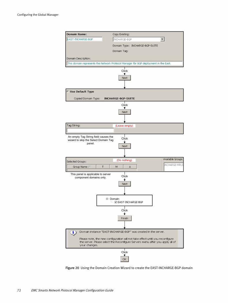
Configuring the Global Manager
Click
Click
Click
(Leave empty)
An empty Tag String field causes the wizard to skip the Select Domain Tag
panel.
This panel is applicable to server component domains only. Click
Click
Click
(Do nothing)
Figure 20 Using the Domain Creation Wizard to create the EAST-INCHARGE-BGP domain
72 EMC Smarts Network Protocol Manager Configuration Guide

Configuring the Global Manager
Click
Click
Click
(Leave empty)
An empty Tag String field causes the wizard to skip the Select Domain Tag
panel.
This panel is applicable to server component domains only. Click
Click
Click
(Do nothing)
Figure 21 Using the Domain Creation Wizard to create the EAST-INCHARGE-AM domain
Specifying the underlying domains 73

Configuring the Global Manager
Procedure for reconfiguring the Global Manager for configuration scenario 2To reconfigure the Global Manager for configuration scenario 2:
1. In the toolbar area of the Global Manager Administration Console, click the Reconfigure toolbar button.
2. In the Server Reconfiguration confirmation dialog box that appears, click Yes.
3. In the Server Reconfiguration information dialog box that appears, click Close.
In response, the Global Manager:
◆ Creates an InChargeDomain object named EAST-INCHARGE-BGP and starts the appropriate topology and event drivers.
◆ Creates an InChargeDomain object named EAST-INCHARGE-AM and starts the appropriate topology and event drivers.
◆ Creates an InChargeDomain object named EAST-INCHARGE-OI and starts the appropriate notification drivers.
◆ Consults the EMC Smarts Broker for the deployment and establishes a connection to the EAST-INCHARGE-BGP, EAST-INCHARGE-AM, and EAST-INCHARGE-OI domains.
◆ Subscribes to and imports topology and events from the EAST-INCHARGE-BGP EAST-INCHARGE-AM domains.
◆ Subscribes to and imports notifications from the EAST-INCHARGE-OI domain.
The Global Manager will establish an additional connection to the EAST-INCHARGE-BGP domain under any of the following circumstances:
◆ To obtain the latest object attribute values for display in the Details tab of a routing-protocol Notification Properties dialog box.
◆ To obtain the latest object attribute values for display in a routing-protocol Containment dialog box.
Similarly, the Global Manager will establish an additional connection to the EAST-INCHARGE-AM domain under any of the following circumstances:
◆ To obtain the latest object attribute values for display in the Details tab of an IP Notification Properties dialog box.
◆ To obtain the latest object attribute values for display in an IP Containment dialog box.
Because no IP Availability Manager application named INCHARGE-AM is running in configuration scenario 2, users should disable the INCHARGE-AM domain for this scenario.
74 EMC Smarts Network Protocol Manager Configuration Guide
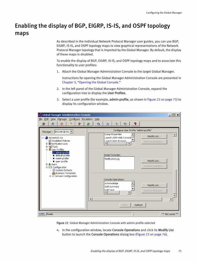
Configuring the Global Manager
Enabling the display of BGP, EIGRP, IS-IS, and OSPF topology maps
As described in the individual Network Protocol Manager user guides, you can use BGP, EIGRP, IS-IS, and OSPF topology maps to view graphical representations of the Network Protocol Manager topology that is imported by the Global Manager. By default, the display of these maps is disabled.
To enable the display of BGP, EIGRP, IS-IS, and OSPF topology maps and to associate this functionality to user profiles:
1. Attach the Global Manager Administration Console to the target Global Manager.
Instructions for opening the Global Manager Administration Console are presented in Chapter 3, “Opening the Global Console.”
2. In the left panel of the Global Manager Administration Console, expand the configuration tree to display the User Profiles.
3. Select a user profile (for example, admin-profile, as shown in Figure 22 on page 75) to display its configuration window.
Figure 22 Global Manager Administration Console with admin-profile selected
4. In the configuration window, locate Console Operations and click its Modify List button to launch the Console Operations dialog box (Figure 23 on page 76).
Enabling the display of BGP, EIGRP, IS-IS, and OSPF topology maps 75

Configuring the Global Manager
Figure 23 Console Operations dialog box
5. In the Console Operations dialog box, expand the Map option and click the following checkboxes:
• BGP Connectivity
• OSPF Connectivity
• OSPF Network Connectivity
• EIGRP Connectivity
• EIGRP Network Connectivity
• ISIS Connectivity
• ISIS Network Connectivity
The default option at the bottom of the dialog box is Other; do not change this default.
6. Click OK to close the Console Operations dialog box.
7. In the configuration window, click Apply to save your configuration changes.
8. Repeat steps 3 through 7 to enable the display of BGP, EIGRP, IS-IS, and OSPF topology maps for any other user profiles that need to see these maps.
9. Detach and reattach the Global Console to the Global Manager in order to view the BGP, EIGRP, IS-IS, and OSPF maps. Start by selecting Manager > Detach.
76 EMC Smarts Network Protocol Manager Configuration Guide

CHAPTER 6Configuring SNMP Trap Integration
This chapter provides instructions for configuring the SNMP trap integration in a Network Protocol Manager deployment. It consists of the following sections:
◆ Configuration overview ........................................................................................... 78◆ SNMP trap-integration components ........................................................................ 79◆ Trap adapter configuration file: trapd.conf .............................................................. 81◆ Configuring the SNMP trap-integration components ................................................ 85◆ Starting the SNMP trap-integration components...................................................... 91
Configuring SNMP Trap Integration 77

Configuring SNMP Trap Integration
Configuration overviewThe recommended SNMP trap-integration design for a Network Protocol Manager deployment is shown in Figure 24 on page 78.
BGP traps(v1, v2c)
Traps(v1, v2c, v3)
Processed traps
Informational traps(v1, v2c)
Network traps
(v1, v2c)
Topology
Trap notifications
IP network(with BGP- and OSPF-enabled devices)
AdapterPlatform
SNMPTrap Adapter(trap receiver)
Global Manager
IP Availability Manager
SNMPTrap Adapter
(trap exploder) OSPF traps(v1, v2c)
Network Protocol Manager for BGP
Network Protocol Manager for OSPF
Discarded,unwanted
traps
Figure 24 Recommended trap-integration design
Configuring the SNMP trap integration involves configuring and starting the various components that receive, distribute, and process the traps within a Network Protocol Manager deployment.
78 EMC Smarts Network Protocol Manager Configuration Guide

Configuring SNMP Trap Integration
SNMP trap-integration componentsThe SNMP trap integration in a Network Protocol Manager deployment is accomplished by using the following types of components:
◆ “Built-in trap receiver” — part of most EMC Smarts Domain Managers
◆ “SNMP Trap Adapter” — part of the Service Assurance Manager
◆ “Adapter Platform” — part of the Service Assurance Manager
Built-in trap receiver
A Network Protocol Manager’s built-in trap receiver receives SNMPv1 and v2c trap messages from managed BGP- or OSPF-enabled devices through the SNMP Trap Adapter that is configured as a trap exploder. The built-in trap receiver forwards these traps to internal processing software, which parses the traps for status updates and applies the updates to attributes of objects in the Network Protocol Manager modeled topology.
By default, the built-in trap receiver is disabled, and should be enabled only if Network Protocol Manager for BGP or Network Protocol Manager for OSPF is running in the deployment:
◆ Network Protocol Manager for BGP uses received BGP traps to update attributes of the BGP objects in its modeled topology.
◆ Network Protocol Manager for OSPF uses received OSPF traps to update attributes of OSPF objects in its modeled topology.
The built-in trap receiver is enabled for Network Protocol Manager for BGP or Network Protocol Manager for OSPF by setting the “TrapPort = 0” parameter line in the bgp.conf or ospf.conf file to a valid trap listening port.
SNMP Trap Adapter
The SNMP Trap Adapter, which is part of the Service Assurance Manager, can be configured to forward traps, or can be configured to convert traps to EMC Smarts notifications.
Two instances of the SNMP Trap Adapter appear in a Network Protocol Manager deployment:
◆ One instance, called a “trap exploder,” that is configured to forward traps
A trap exploder is also known as a “trap forwarder.”
◆ Another instance, called a “trap receiver,” that is configured to convert traps
Trap exploder operationThe EMC Smarts Service Assurance Manager Adapter Platform User Guide describes the operation of an SNMP Trap Adapter that is configured as a trap exploder. The operation is based on the parameter settings in the trapd.conf file that is described in “Trap adapter configuration file: trapd.conf” on page 81.
SNMP trap-integration components 79

Configuring SNMP Trap Integration
In a Network Protocol Manager deployment (Figure 24 on page 78), the trap exploder receives SNMPv1, v2c, or v3 traps from the managed network devices on its trap listening port (9000 by default), and:
◆ Forwards copies of received BGP traps to Network Protocol Manager for BGP, to be used by Network Protocol Manager for BGP for analysis purposes.
◆ Forwards copies of received OSPF traps to Network Protocol Manager for OSPF, to be used by Network Protocol Manager for OSPF for analysis purposes.
◆ Forwards copies of received network traps to IP Availability Manager, to be used by IP Availability Manager for analysis purposes.
◆ Forwards copies of received useful or interesting traps to the trap receiver, to be used by users for informational purposes.
When a trap arrives, the trap exploder reads the uncommented FORWARD entries in the trapd.conf file to determine which destinations should receive the forwarded trap. When the criteria of the trap matches the criteria of a FORWARD entry, the trap exploder:
◆ Translates the trap in accordance to Table 9 on page 80.
◆ Sends a copy of the forwarded trap to each destination specified in the FORWARD entry.
Table 9 Trap exploder translation of incoming traps to forwarded traps
Incoming trap message version Forwarded trap message version
The trap exploder authenticates and decrypts received SNMPv3 traps, converts them to SNMPv2c traps, and forwards the SNMPv2c traps to the configured destinations. The trap exploder uses the authentication and privacy credentials obtained from a seed file, which is typically a copy of the seed file maintained by an IP Availability Manager for discovery purposes, to authenticate and decrypt SNMPv3 traps.
Trap receiver operationThe EMC Smarts Service Assurance Manager Adapter Platform User Guide describes the operation of a SNMP Trap Adapter that is configured as a trap receiver. The operation is based on the parameter settings in the trap_mgr.conf file in the BASEDIR/smarts/conf/icoi directory in the Service Assurance Manager installation area.
The purpose of the trap receiver is to collect and parse informational traps received from the trap exploder, and to generate EMC Smarts notifications, through the Adapter Platform, for input to the Global Manager. Through the Global Console, administrators and operators view and acknowledge the trap notifications.
v1 v1
v2c v2c
v3
80 EMC Smarts Network Protocol Manager Configuration Guide

Configuring SNMP Trap Integration
Adapter Platform
The Adapter Platform imports and normalizes topology from IP Availability Manager, and imports and normalizes events of interest from EMC Smarts adapters such as the SNMP Trap Adapter. Normalize means to convert topology or event information into a common form that is understood by the Global Manager. The normalized event information is transferred as EMC Smarts notifications to the Global Manager.
Through the Adapter Platform, the Global Manager receives informational traps issued by the devices in the managed network. Informational traps provide information that might be of interest to users.
Trap adapter configuration file: trapd.confThe trapd.conf file, located in the BASEDIR/smarts/conf/trapd directory of all EMC Smarts product installations, is a global configuration file. It is used to configure most EMC Smarts built-in trap receivers and most trap adapters (sm_trapd). Only the PORT parameter in this file is applicable to built-in trap receivers because the built-in trap receivers are configured to receive and parse traps, but not to forward traps. The other parameters in the file are applicable for configuring trap adapters to forward traps.
The built-in trap receiver for Network Protocol Manager is not controlled by the trapd.conf file. The only user-configurable control for the built-in trap receiver is the “TrapPort = 0” parameter line in the bgp.conf and ospf.conf files.
Figure 25 on page 81 shows the trap exploder’s configuration directory, in the Service Assurance Manager installation area, and the trap exploder’s trapd.conf file. A trapd.conf file in the local area takes precedence over the original trapd.conf file, which contains the installed defaults. A seedfile is required only if the trap exploder is to process SNMPv3 traps.
BASEDIR
ics
conf
smarts
ics
conf
local
trapd.conf
trapd
trapd.conf
trapd
Original files Modified files
Trap exploderconfiguration
directory
Trap exploderconfiguration
directory(local)
seedfile
seedfile
Figure 25 Configuration directory for a trap exploder
Trap adapter configuration file: trapd.conf 81

Configuring SNMP Trap Integration
The following portions of the trapd.conf file are of interest to this discussion. Table 10 on page 83 presents detailed descriptions of the configuration parameters in the trapd.conf file.
# trapd.conf - Configuration file for SNMP Trap Adapter...# Following is a list of parameters with a brief description.# More information is available at the end of this file.## PORT UDP port number the trap adapter listens to.## WINDOW De-duplication window, in seconds.## ASCII Controls formatting of non-printable characters.## TAG Enables tagging of varbind values.## ENABLE_FWD Enables trap forwarding.## MATCH Determines whether traps are tested against all forwarding # criteria or up to the first criterion that matches.## FORWARD Specifies matching criteria for traps and the forwarding # destinations for matched traps.
############ Set the parameters here.
PORT: 9000
#WINDOW: 10
#ASCII: FALSE
#TAG: FALSE
ENABLE_FWD: TRUE
#MATCH: all
#QUEUE_LIMIT_MEGS: 0
#QUEUE_LIMIT_SECONDS: 0...# Traps required by InCharge IP Availability Manager (AM)## Generic: coldStart, warmStart, LinkUp, LinkDown#FORWARD: * .* <0-3> * host:port...# Traps required by InCharge IP Performance Manager (PM)## Cisco: EnvMon Voltage, Temperature, Fan, RedundantSupply#FORWARD: * .1.3.6.1.4.1.9.9.13.3 6 <2-5> host:port...
82 EMC Smarts Network Protocol Manager Configuration Guide

Configuring SNMP Trap Integration
Table 10 Configuration parameters in the trapd.conf file (page 1 of 2)
Parameter Description
PORT UDP port number on which the trap receiver or trap adapter listens for traps.Valid values are 0-65535. The default port is 9000.
WINDOW De-duplication window, in seconds. The maximum amount of time between receiving similar traps before the second trap is considered unique.Valid values are nonnegative integers, including 0. The default is 0.If not set or set to 0, the de-duplication feature is disabled, which means that all traps are considered unique.
ASCII No longer used; should remain FALSE (default).
TAG Enables tagging of variable-binding (varbind) values.Valid values are TRUE and FALSE. The default is FALSE.• When TRUE, the type of the varbind value appears before each value; for example,
INTEGER-32 3.• When FALSE, the type of the varbind value does not appear before each value.
QUEUE_LIMIT_MEGS Limits the size of internal trap queue to the stated size, in megabytes.Valid values are nonnegative integers, including 0. The default is 0, which means that there is no limit on the size of the internal trap queue.
Note: The limit is not exact: The queue may grow slightly larger than the value specified.
When the limit is reached, some traps will be discarded.
QUEUE_LIMIT_SECONDS Limits the time that a trap can spend in the internal trap queue, in seconds.Valid values are nonnegative integers, including 0. The default is 0, which means that there is no limit on the time that a trap can spend in the internal trap queue.
Note: This limit is even less exact than the limit set for QUEUE_LIMIT_MEGS. In general, you should specify values for both QUEUE_LIMIT_MEGS and QUEUE_LIMIT_SECONDS.
When the limit is reached, some traps will be discarded.
ENABLE_FWD Determines whether uncommented FORWARD parameters are enabled or disabled.Valid values are TRUE and FALSE. The default is TRUE.• When TRUE, uncommented FORWARD parameters are enabled: Trap forwarding
statements specified in uncommented FORWARD parameters are read.• When FALSE, uncommented FORWARD parameters are disabled: Trap forwarding
statements specified in uncommented FORWARD parameters are not read.
MATCH Determines whether traps are tested against all matching criteria that are specified in an uncommented FORWARD parameter, or tested up to the first criterion that matches.Valid values are “all” or “first.” The default is “first.”If no uncommented FORWARD parameters are specified, the MATCH parameter is ignored.
Trap adapter configuration file: trapd.conf 83

Configuring SNMP Trap Integration
FORWARD Specifies matching criteria for traps and the forwarding destinations for matched traps.Valid syntax is:
<source device address> <OID> <generic type> <specific type> \ <destination host address>[:<port>|:<port>:<community>] \ [<destination host address>[:<port>|:<port>:<community>]] ...
where:• <source device address> is the IP address of the object (SNMP agent) generating
the trap.• <OID> is the sysObjectID of the type of object generating the trap.• <generic type> is the generic trap type:
0 coldStart1 warmStart2 linkDown3 linkUp4 authenticationFailure5 egpNeighborLoss6 enterpriseSpecific
Valid syntax for <generic type> is a generic specific trap number (for example, 3), a range of generic specific trap numbers (for example, <3-5>), or any generic specific trap number (for example, *). An asterisk is a wildcard character that matches any arbitrary string of characters.
• <specific type> is the specific trap code, present even if <generic type> is not enterpriseSpecific (6).Valid syntax for <specific type> is an enterprise specific trap number (for example, 733), a range of enterprise specific trap numbers (for example, <130-156>), or any enterprise specific trap number (for example, *).
• <destination host address> is the IP address (for example, 192.35.144.12) or the hostname (for example, gifted.mycompany.com) of the destination host.
• <port> is the trap listening port on the destination host. Port is optional; if not specified, port defaults to 162.
• <community> is the community string to be assigned to the community string field in the forwarded traps. Community is optional; if not specified, community defaults to the value specified in the community string field of the incoming v1 or v2c trap, and defaults to an empty string for an incoming v3 trap.
Wildcards are allowed for all fields except destination host address, port, and community. Wildcard syntax is discussed in Appendix A, “Wildcard Patterns.”Examples:FORWARD: * .* * * snake:9099:public1All traps received from all network devices will be sent to port 9099 on a host named “snake”; the community string “public1” will be assigned to the forwarded traps.FORWARD: 193.20.*.* .* <0-5> * obelix:7000 surya 194.56.78.23:9000All generic traps (0 to 5) from network devices whose address matches 193.20.*.* will be sent to:• Port 7000 on a host named “obelix.”• Port 162 on a host named “surya.”• Port 9000 on a host identified by address 194.56.78.23.Other trap forwarding examples are presented at the end of the trapd.conf file.
Table 10 Configuration parameters in the trapd.conf file (page 2 of 2)
Parameter Description
84 EMC Smarts Network Protocol Manager Configuration Guide
Configuring SNMP Trap Integration
Configuring the SNMP trap-integration componentsBefore starting the SNMP trap-integration components in a Network Protocol Manager deployment, you must configure them so that they can receive, distribute, and process traps properly at startup.
The configuration steps are:
◆ “Configure the trap exploder” to receive traps from the managed network devices and to distribute BGP and OSPF traps to Network Protocol Manager, network traps to IP Availability Manager, and informational traps to the trap receiver.
◆ “Configure the built-in trap receivers” of Network Protocol Manager and IP Availability Manager to receive the traps forwarded by the trap exploder.
◆ “Configure the trap receiver” to receive the informational traps forwarded by the trap exploder and to convert the traps into EMC Smarts notifications.
◆ “Configure the Adapter Platform” to import topology from IP Availability Manager for the purpose of associating EMC Smarts notifications with the appropriate topology objects.
Configure the trap exploder
Whenever it starts up, the trap exploder reads the trapd.conf file and an optional seed file in the following directory in the Service Assurance Manager installation area:
BASEDIR/smarts/local/conf/trapd
The trap exploder sets its configurations to the configuration settings in its trapd.conf file. It reads all of the uncommented parameters in the trapd.conf file, including the PORT parameter, which is set to 9000 by default.
The trap exploder uses the credentials in its seed file to authenticate and decrypt SNMPv3 traps received from SNMPv3-capable devices in the managed network. This seed file is separate from the seed file used by IP Availability Manager for discovery.
Procedure for configuring the trap exploderTo configure the trap exploder, you open and edit the Service Assurance BASEDIR/smarts/conf/trapd/trapd.conf file to forward the appropriate traps to Network Protocol Manager, IP Availability Manager, and the trap receiver. You use the FORWARD parameter in the trapd.conf file to determine which incoming traps are sent to what destinations.
In addition to configuring the trapd.conf file, you need to configure the managed network devices to forward SNMP traps to the host where the trap exploder is running, and to the port on which the trap exploder is listening for traps.
If no --port=<port number> option is specified in the trap exploder’s startup command, the trap exploder listens for traps on the port specified by the PORT parameter in the trapd.conf file (port 9000 by default), or port 162 if no PORT value is specified in the trapd.conf file. The trap exploder startup options are described in “Start the trap exploder” on page 92.
Figure 26 on page 86 maps the steps (circled numbers) in the trap exploder configuration procedure to the configured forwarded trap paths.
Configuring the SNMP trap-integration components 85
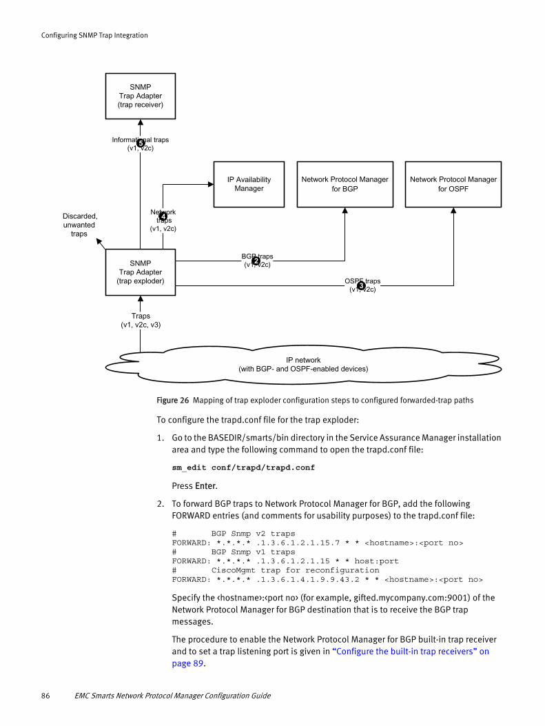
Configuring SNMP Trap Integration
BGP traps(v1, v2c)
Traps(v1, v2c, v3)
Informational traps(v1, v2c)
Network traps
(v1, v2c)
IP network(with BGP- and OSPF-enabled devices)
SNMPTrap Adapter(trap receiver)
IP Availability Manager
SNMPTrap Adapter
(trap exploder) OSPF traps(v1, v2c)
Network Protocol Manager for BGP
Network Protocol Manager for OSPF
Discarded,unwanted
traps
2
5
4
3
Figure 26 Mapping of trap exploder configuration steps to configured forwarded-trap paths
To configure the trapd.conf file for the trap exploder:
1. Go to the BASEDIR/smarts/bin directory in the Service Assurance Manager installation area and type the following command to open the trapd.conf file:
sm_edit conf/trapd/trapd.conf
Press Enter.
2. To forward BGP traps to Network Protocol Manager for BGP, add the following FORWARD entries (and comments for usability purposes) to the trapd.conf file:
# BGP Snmp v2 trapsFORWARD: *.*.*.* .1.3.6.1.2.1.15.7 * * <hostname>:<port no># BGP Snmp v1 trapsFORWARD: *.*.*.* .1.3.6.1.2.1.15 * * host:port# CiscoMgmt trap for reconfigurationFORWARD: *.*.*.* .1.3.6.1.4.1.9.9.43.2 * * <hostname>:<port no>
Specify the <hostname>:<port no> (for example, gifted.mycompany.com:9001) of the Network Protocol Manager for BGP destination that is to receive the BGP trap messages.
The procedure to enable the Network Protocol Manager for BGP built-in trap receiver and to set a trap listening port is given in “Configure the built-in trap receivers” on page 89.
86 EMC Smarts Network Protocol Manager Configuration Guide
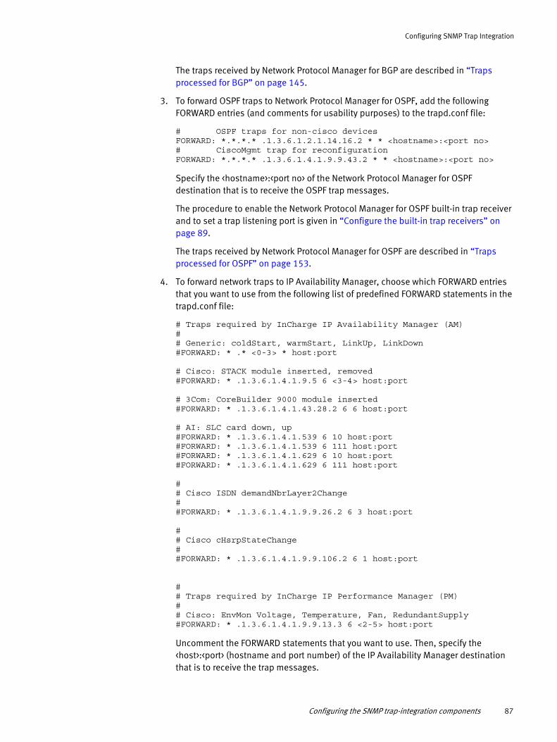
Configuring SNMP Trap Integration
The traps received by Network Protocol Manager for BGP are described in “Traps processed for BGP” on page 145.
3. To forward OSPF traps to Network Protocol Manager for OSPF, add the following FORWARD entries (and comments for usability purposes) to the trapd.conf file:
# OSPF traps for non-cisco devicesFORWARD: *.*.*.* .1.3.6.1.2.1.14.16.2 * * <hostname>:<port no># CiscoMgmt trap for reconfigurationFORWARD: *.*.*.* .1.3.6.1.4.1.9.9.43.2 * * <hostname>:<port no>
Specify the <hostname>:<port no> of the Network Protocol Manager for OSPF destination that is to receive the OSPF trap messages.
The procedure to enable the Network Protocol Manager for OSPF built-in trap receiver and to set a trap listening port is given in “Configure the built-in trap receivers” on page 89.
The traps received by Network Protocol Manager for OSPF are described in “Traps processed for OSPF” on page 153.
4. To forward network traps to IP Availability Manager, choose which FORWARD entries that you want to use from the following list of predefined FORWARD statements in the trapd.conf file:
# Traps required by InCharge IP Availability Manager (AM)## Generic: coldStart, warmStart, LinkUp, LinkDown#FORWARD: * .* <0-3> * host:port
# Cisco: STACK module inserted, removed#FORWARD: * .1.3.6.1.4.1.9.5 6 <3-4> host:port
# 3Com: CoreBuilder 9000 module inserted#FORWARD: * .1.3.6.1.4.1.43.28.2 6 6 host:port
# AI: SLC card down, up#FORWARD: * .1.3.6.1.4.1.539 6 10 host:port#FORWARD: * .1.3.6.1.4.1.539 6 111 host:port#FORWARD: * .1.3.6.1.4.1.629 6 10 host:port#FORWARD: * .1.3.6.1.4.1.629 6 111 host:port
## Cisco ISDN demandNbrLayer2Change##FORWARD: * .1.3.6.1.4.1.9.9.26.2 6 3 host:port
## Cisco cHsrpStateChange##FORWARD: * .1.3.6.1.4.1.9.9.106.2 6 1 host:port
## Traps required by InCharge IP Performance Manager (PM)## Cisco: EnvMon Voltage, Temperature, Fan, RedundantSupply#FORWARD: * .1.3.6.1.4.1.9.9.13.3 6 <2-5> host:port
Uncomment the FORWARD statements that you want to use. Then, specify the <host>:<port> (hostname and port number) of the IP Availability Manager destination that is to receive the trap messages.
Configuring the SNMP trap-integration components 87

Configuring SNMP Trap Integration
The procedure to change the trap listening port (port 9000 by default) of the IP Availability Manager built-in trap receiver is given in “Procedure to configure the IP Availability Manager built-in trap receiver” on page 90.
5. To forward informational traps to the trap receiver, add your choice of FORWARD entries to the trapd.conf file:
# Traps for Trap Receiver and Adapter Platform<Add your matching criteria for the traps and the forwarding destination: the IP address and trap port of the trap receiver.>
Specify the <hostname>:<port no> of the trap receiver destination that is to receive the trap messages.
By default, the trap receiver listens for traps on port 9000. Insight into how to change this port number is given in “Configure the trap receiver” on page 90.
6. Ensure that the ENABLE_FWD parameter is TRUE (default).
7. Save and close the file.
The modified version of the trapd.conf file is saved to the BASEDIR/smarts/local/conf/trapd directory in the Service Assurance Manager installation area.
Any received trap not matching any of the FORWARD entries is discarded.
Procedure for enabling the trap exploder to process SNMPv3 trapsPerform this procedure only if the trap exploder is to process SNMPv3 traps. The procedure consists of placing a copy of an IP Availability Manager seed file in the BASEDIR/smarts/conf/trapd directory in the Service Assurance Manager installation area.
It is assumed that you have already created a seed file for IP Availability Manager discovery purposes. Typically, you create a seed file by using the sm_edit utility to open and add seed entries to a template file named seedfile, located in the BASEDIR/smarts/conf directory in the IP Manager installation area.
IP Availability Manager uses the seed entries and their credentials to contact the seed systems during discovery. The trap exploder uses the entries and their credentials to verify and decrypt SNMPv3 trap messages received from SNMPv3-capable seed systems once the seed systems are discovered.
To enable the trap exploder to process SNMPv3 traps:
1. In the IP Manager installation area, make a copy of the seed file that was created for discovery purposes and save it to the BASEDIR/smarts/conf/trapd directory in the Service Assurance Manager installation area. The seed filename must match the name specified in the --seed option of the trap exploder startup command.
2. In the Service Assurance Manager installation area, go to the BASEDIR/smarts/bin directory and type the following command to open the seed file.
sm_edit conf/trapd/<seed file>
Press Enter.
3. Modify the seed file as appropriate for your deployment.
88 EMC Smarts Network Protocol Manager Configuration Guide

Configuring SNMP Trap Integration
4. Save and close the file.
The modified version of the seed file is saved to the BASEDIR/smarts/local/conf/trapd directory in the Service Assurance Manager installation area.
5. If the trap exploder was running before you edited the seed file, restart the trap exploder.
Configure the built-in trap receivers
By default, the built-in trap receiver for Network Protocol Manager for BGP or Network Protocol Manager for OSPF is disabled. Follow the instructions in the “Procedure to configure the Network Protocol Manager built-in trap receiver” on page 89 to enable the built-in trap receiver and to set its port number to the destination port specified for Network Protocol Manager in the trap exploder’s trapd.conf file.
By default, the built-in trap receiver for IP Availability Manager listens for traps on port 9000. Follow the instructions in the “Procedure to configure the IP Availability Manager built-in trap receiver” on page 90 section to set the port number of the built-in trap receiver to the destination port specified for IP Availability Manager in the trap exploder’s trapd.conf file.
Procedure to configure the Network Protocol Manager built-in trap receiverTo configure the Network Protocol Manager built-in trap receiver:
1. Go to the BASEDIR/smarts/bin directory in the Network Protocol Manager installation area and type the following command to open the bgp.conf or ospf.conf file:
sm_edit conf/bgp/bgp.conf-or-sm_edit conf/ospf/ospf.conf
Press Enter.
2. Find the following line:
TrapPort = 0
TrapPort = 0 disables the built-in trap receiver.
3. Set the port number (0) to the destination port specified for Network Protocol Manager for BGP or Network Protocol Manager for OSPF in the trap exploder’s trapd.conf file.
A valid port number is 162 or any value in the range 2049 to 65534 inclusive.
4. Save and close the file.
The modified version of the bgp.conf file is saved to the BASEDIR/smarts/local/conf/bgp directory, or the modified version of the ospf.conf file is saved to the BASEDIR/smarts/local/conf/ospf directory.
5. If Network Protocol Manager was running before you edited the bgp.conf or ospf.conf file, restart Network Protocol Manager.
Configuring the SNMP trap-integration components 89

Configuring SNMP Trap Integration
Procedure to configure the IP Availability Manager built-in trap receiverTo configure the IP Availability Manager built-in trap receiver:
1. Go to the BASEDIR/smarts/bin directory in the IP Manager installation area and type the following command to open the trapd.conf file:
sm_edit conf/trapd/trapd.conf
Press Enter.
2. Set the port number of the following PORT entry to the destination port specified for IP Availability Manager in the trap exploder’s trapd.conf file:
PORT: <port number>
A valid port number is 162 or any value in the range 2049 to 65534 inclusive.
3. Save and close the file.
The modified version of the trapd.conf file is saved to the BASEDIR/smarts/local/conf/trapd directory in the IP Manager installation area.
4. If IP Availability Manager was running before you edited the trapd.conf file, restart IP Availability Manager.
Configure the trap receiver
To configure the trap receiver to process informational traps received from the trap exploder, you edit the Service Assurance BASEDIR/smarts/conf/icoi/trap_mgr.conf file to define how the trap receiver processes traps into notifications. Each trap to be transformed into a notification requires a trap definition entry in the trap_mgr.conf file.
The trap_mgr.conf file contains rules that the trap receiver uses to map incoming traps into the data fields of an EMC Smarts notification. The Adapter Platform, in turn, creates the EMC Smarts notification object from the data fields and exports the notification to the Global Manager.
If no --port=<port number> option is specified in the trap receiver’s startup command, the trap receiver listens for traps on the port specified by the PORT parameter in the Service Assurance BASEDIR/smarts/conf/icoi/trapd.conf file (port 9000 by default), or port 162 if no PORT value is specified in the trapd.conf file. The trap exploder startup options are described in the EMC Smarts Service Assurance Manager Adapter Platform User Guide and the EMC Smarts Installation Guide for SAM, IP, ESM, MPLS, NPM, OTM, and VoIP Managers.
To configure the trap_mgr.conf file for the trap receiver:
1. Go to the BASEDIR/smarts/bin directory in the Service Assurance Manager installation area and type the following command to open the trap_mgr.conf file:
sm_edit conf/icoi/trap_mgr.conf
Press Enter.
2. Define a trap definition for each received trap.
For each SNMP trap, you must specify how the information in the trap maps to objects in the Global Manager repository and how the notification should appear at the Global Console.
90 EMC Smarts Network Protocol Manager Configuration Guide
Configuring SNMP Trap Integration
3. Save the file.
The modified version of the trap_mgr.conf file is saved to the BASEDIR/smarts/local/conf/icoi directory in the Service Assurance Manager installation area.
Configure the Adapter Platform
To configure the Adapter Platform, you attach the Global Manager to the Adapter Platform and specify the underlying IP Availability Manager domain or domains. Doing so enables the Adapter Platform to import hostnames and IP addresses from the underlying IP Availability Manager domains so that it can accurately relate events in received traps to the devices that are associated with the events. The Adapter Platform creates EMC Smarts notification objects from the events, and exports the notifications to the Global Manager.
The procedure to configure the Adapter Platform is identical to the procedure that is presented in “Specifying the underlying domains” on page 65.
To attach the Global Manager Administration Console to your Adapter Platform:
1. In the Global Manager Administration Console, select Manager > Attach to display the Attach Manager dialog box.
2. In the Attach Manager dialog box, enter the Adapter Platform name and the login information (for example, admin and changeme) and click OK.
3. In the Global Manager Administration Console, select the Adapter Platform name from the Manager drop-down menu.
The EMC Smarts Service Assurance Manager Adapter Platform User Guide provides a complete description of the Adapter Platform.
Starting the SNMP trap-integration componentsIn a Network Protocol Manager deployment, you install the following products as services so that the host system automatically starts them as processes that run in the background each time that the system boots:
◆ EMC Smarts Broker
◆ Network Protocol Manager
◆ IP Availability Manager
◆ Global Manager
◆ Global Console
◆ Adapter Platform
◆ SNMP Trap Adapter (trap exploder and trap receiver)
The services for these products are described in detail in the EMC Smarts Installation Guide for SAM, IP, ESM, MPLS, NPM, OTM, and VoIP Managers.
You cannot install the SNMP Trap Adapter (trap exploder) as a service, but you can use the sm_service command to register this adapter as a service after the installation. This section describes how to create and start a service for the SNMP Trap Adapter that is configured as a trap exploder.
Starting the SNMP trap-integration components 91

Configuring SNMP Trap Integration
Typically, in any EMC Smarts deployment, the order in which the applications are started is not important, except that the Broker must be started first.
Start the trap exploder
Use the sm_service command to manually create a service for the trap exploder. A typical service command on a UNIX host would look like this:
/opt/InCharge/SAM/smarts/bin/sm_service install--force--unmanaged--startmode=runonce--name=ic-trap-exploder--description=”EMC Smarts SNMP Trap Exploder”/opt/InCharge/SAM/smarts/bin/sm_trapd--name=INCHARGE-EXPLODER--config=trapd--port=162--rules=default--output
where:
◆ --name=<name>
Second --name option (--name=INCHARGE-EXPLODER) in the service command: Specifies the trap exploder name to be registered with the Broker for the deployment. Also -n <name>.
◆ --config=<cfg>
Specifies the configuration directory in which the trapd.conf file for the trap exploder is located. The trapd.conf file is loaded from the BASEDIR/smarts/local/conf/<cfg> directory, or from the BASEDIR/smarts/conf/<cfg> directory if the trapd.conf file is not present in the local directory. The default configuration (<cfg>) directory for the trap exploder is trapd.
Ensure that --config is set to trapd in the trap exploder service command.
◆ --port=<trap listening port>
Specifies the port number to which the managed network devices send traps and on which the trap exploder listens for traps. Also -p <trap listening port>.
The default trap listening port is the PORT parameter value in the <cfg>/trapd.conf file (port 9000 by default), or port 162 if no PORT value is specified in the <cfg>/trapd.conf file.
92 EMC Smarts Network Protocol Manager Configuration Guide

Configuring SNMP Trap Integration
◆ --sport=<Remote API listening port>
Specifies the port number on which the trap exploder listens for Remote API connections from other EMC Smarts programs, including the Global Console, servers, and utilities such as dmctl. This option is meaningful only if the --name option is specified. Also -P <Remote API listening port>.
The --sport option for the sm_trapd program plays the same role as the --port option plays for any other EMC Smarts program. The --sport option is unique to the sm_trapd program and defaults to 0.
--sport=0 is interpreted by the host operating system as meaning “assign this program a unique, unused port number.” Typically, the operating system responds by assigning a unique, unused port number in the range 40000–65535.
◆ --rules=default
Specifies the rule set to be used by the trap exploder. The default rule set is defined in the BASEDIR/smarts/rules/trapd/trapParse.asl file.
◆ --output
Specifies that the stdout and stderr output for the trap exploder should be redirected to a log file in the BASEDIR/smarts/local/logs directory. The name of the log file is INCHARGE-EXPLODER_<locale>_<character encoding>.log; for example, INCHARGE-EXPLODER_en_US_UTF-8.log.
The command for starting the example service is:
/opt/InCharge/SAM/smarts/bin/sm_service start ic-trap-exploder
At startup, the trap exploder reads the trapd.conf file and saves the configuration information in its repository.
The EMC Smarts System Administration Guide provides more details about sm_service.
Starting the SNMP trap-integration components 93

Configuring SNMP Trap Integration
94 EMC Smarts Network Protocol Manager Configuration Guide

CHAPTER 7Configuring Syslog Message Processing and Forwarding
This chapter provides instructions for configuring syslog message processing and forwarding in a Network Protocol Manager deployment. It consists of the following sections:
◆ Configuration overview ........................................................................................... 96◆ Syslog adapters ...................................................................................................... 97◆ Configuring syslog message processing and forwarding.......................................... 97◆ Configuring syslog message processing .................................................................. 98
Configuring Syslog Message Processing and Forwarding 95
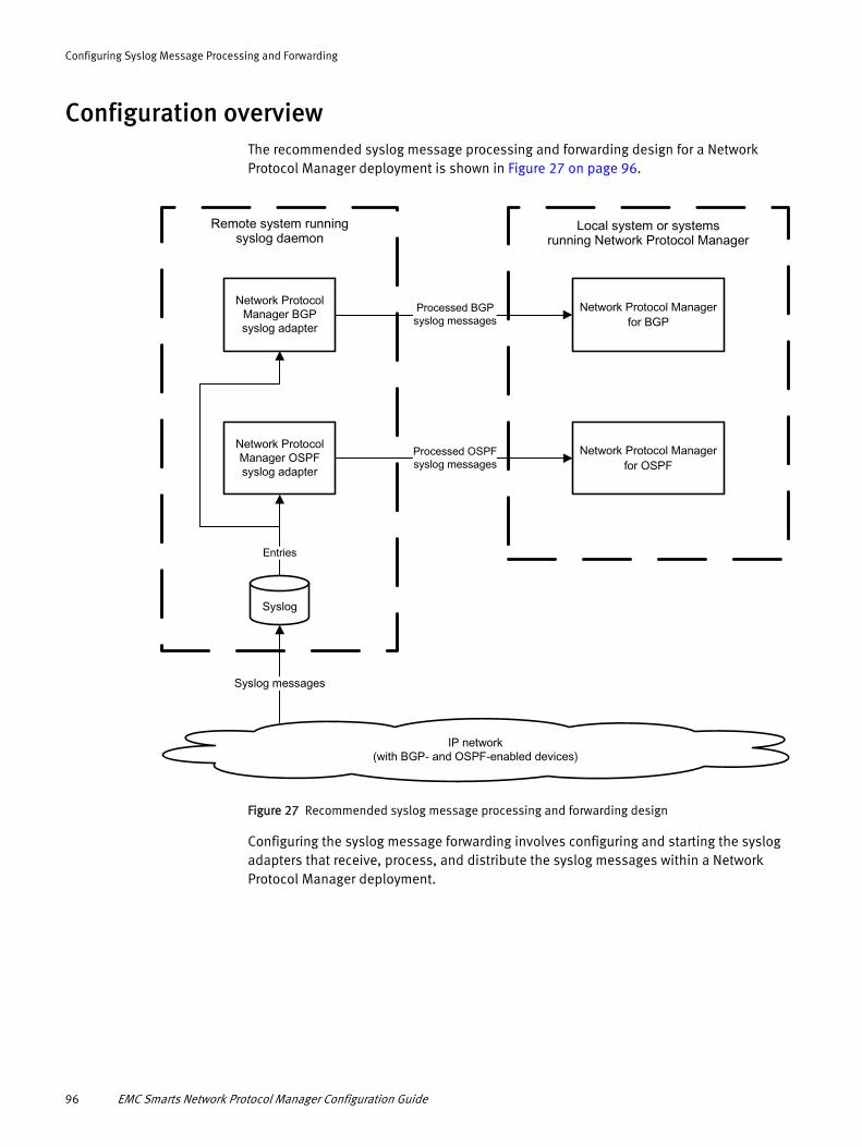
Configuring Syslog Message Processing and Forwarding
Configuration overviewThe recommended syslog message processing and forwarding design for a Network Protocol Manager deployment is shown in Figure 27 on page 96.
Processed BGPsyslog messages
IP network(with BGP- and OSPF-enabled devices)
Network Protocol Manager for BGP
Network Protocol Manager for OSPF
Remote system runningsyslog daemon
Local system or systemsrunning Network Protocol Manager
Syslog messages
Entries
Network Protocol Manager BGPsyslog adapter
Network Protocol Manager OSPFsyslog adapter
Syslog
Processed OSPFsyslog messages
Figure 27 Recommended syslog message processing and forwarding design
Configuring the syslog message forwarding involves configuring and starting the syslog adapters that receive, process, and distribute the syslog messages within a Network Protocol Manager deployment.
96 EMC Smarts Network Protocol Manager Configuration Guide
Configuring Syslog Message Processing and Forwarding
Syslog adaptersA Network Protocol Manager installation includes a built-in syslog adapter that can be configured to:
◆ Fetch BGP- or OSPF-related syslog message from a syslog (system log).
◆ Parse the messages for status updates.
◆ Distribute the status updates to Network Protocol Manager for BGP or Network Protocol Manager for OSPF.
Network Protocol Manager for BGP uses the status updates to update the attributes of BGP objects in its modeled topology, and Network Protocol Manager for OSPF uses the status updates to update the attributes of OSPF objects in its modeled topology.
The syslog messages that are processed by Network Protocol Manager for BGP and Network Protocol Manager for OSPF are described in Appendix C, “Syslog Messages Processed.”
Configuring syslog message processing and forwardingFor the syslog message processing and forwarding scenario, a syslog daemon that is running on a remote system collects the syslog messages from the managed devices that are running the BGP or OSPF protocols. The daemon then writes the messages to a single syslog file on the remote system.
A user installs a separate instance of the Network Protocol Manager on the remote system and manually starts two instances of the built-in syslog adapter:
◆ An instance started as a BGP syslog adapter to serve Network Protocol Manager for BGP.
◆ An instance started as an OSPF syslog adapter to serve Network Protocol Manager for OSPF.
To configure syslog message processing and forwarding:
1. On the local system, where the Network Protocol Manager for BGP or Network Protocol Manager for OSPF reside, ensure that the value of the SyslogName parameter in the BASEDIR/smarts/conf/bgp/bgp.conf file or the BASEDIR/smarts/conf/ospf/ospf.conf file is set to "" (empty string).
2. On the remote system, where the syslog file resides, install an instance of the Network Protocol Manager.
During the installation, do not install any of the Network Protocol Manager products as services.
3. On the remote system, go to the BASEDIR/smarts/bin directory in the Network Protocol Manager installation area and start the syslog adapters.
A sample command line for a target Network Protocol Manager for BGP named INCHARGE-BGP is:
sm_adapter --name=INCHARGE-BGP-SYSLOG --server=INCHARGE-BGP --output=BGP-SYSLOG --daemon --tail=<full path to log file> bgp/bgp-syslog.asl
Syslog adapters 97
Configuring Syslog Message Processing and Forwarding
A sample command line for a target Network Protocol Manager for OSPF named INCHARGE-OSPF is:
sm_adapter --name=INCHARGE-OSPF-SYSLOG --server=INCHARGE-OSPF --output=OSPF-SYSLOG --daemon --tail=<full path to log file> ospf/ospf-syslog.asl
The sm_adapter command is described in the HTML pages that are located in the BASEDIR/smarts/doc/html/usage directory of any Domain Manager installation area.
Configuring syslog message processingIn those cases where the syslog daemon and Network Protocol Manager for BGP and Network Protocol Manager for OSPF are running on the same system, a user does not need to install a separate instance of the Network Protocol Manager to start the BGP and OSPF syslog adapters. Instead, a user starts the BGP and OSPF syslog adapters by assigning the full path and name of the local syslog file to the SyslogName parameter in the bgp.conf or ospf.conf file. For this scenario, the syslog adapters are started automatically when Network Protocol Manager for BGP and Network Protocol Manager for OSPF are started.
To configure syslog message processing:
1. Go to the BASEDIR/smarts/bin directory in the Network Protocol Manager installation area and type the following command to open the bgp.conf or ospf.conf file:
sm_edit conf/bgp/bgp.conf-or-sm_edit conf/ospf/ospf.conf
Press Enter.
2. Find the following line:
SyslogName = ""
SyslogName = "" disables the built-in syslog adapter.
3. Replace the empty string ("") with the full path and name of the syslog file on the local system. For example:
SyslogName = /var/adm/messages
4. Save and close the file.
The modified version of the bgp.conf file is saved to the BASEDIR/smarts/local/conf/bgp directory, or the modified version of the ospf.conf file is saved to the BASEDIR/smarts/local/conf/ospf directory.
5. If Network Protocol Manager was running before you edited the bgp.conf or ospf.conf file, restart Network Protocol Manager.
98 EMC Smarts Network Protocol Manager Configuration Guide

CHAPTER 8Configuring SSH Security
This chapter presents an overview of Secure Shell (SSH) security and provides instructions for configuring SSH in a Network Protocol Manager deployment. It consists of the following sections:
◆ SSH overview........................................................................................................ 100◆ CLI modules for Network Protocol Manager ........................................................... 102◆ SSH client configuration........................................................................................ 105◆ SSH server configuration....................................................................................... 106
Configuring SSH Security 99

Configuring SSH Security
SSH overviewLike Telnet, SSH is a protocol for logging in to a remote host and executing commands on the remote host. Unlike Telnet, SSH uses special algorithms to encrypt the data stream, to ensure data stream integrity, and even to perform authentication in a safe and secure way. SSH is a secure, encrypted replacement for Telnet.
SSH provides remote command line interface (CLI) administration over an authenticated, encrypted connection. In a Network Protocol Manager deployment, Network Protocol Manager for EIGRP and Network Protocol Manager for IS-IS use SSH CLI to query EIGRP- and IS-IS-enabled Cisco devices for topology and status information.
SSH1 and SSH2
Two versions of the SSH protocol exist: SSH1 and SSH2. The two versions are different in terms of their underlying workings.
SSH1 is a simpler protocol than SSH2, and is available on a wider variety of platforms than SSH2. SSH1 has more options for authentication than SSH2, and performs better than SSH2.
On the down side, SSH1 has serious structural weaknesses that leave it vulnerable to a broad number of attacks. These weaknesses have been corrected in SSH2. Because the security enhancements in SSH2 would not have been possible if protocol-level compatibility with SSH1 had been retained, SSH1 and SSH2 are not compatible with one another.
SSH Communications Security, the original developer of the SSH protocol, considers the SSH1 protocol deprecated and recommends that SSH1 not be used.
SSH authentication
Figure 28 on page 100 shows an SSH connection between a client and a server.
SSH client
Network Protocol Manager
SSH server
Cisco router
SSH connection ServerUserNPMUser
Client Server
Figure 28 SSH connection between a Network Protocol Manager host and a Cisco router
The client is the SSH client software that connects users to the SSH server on the remote host. The server is the SSH server program, or ssh daemon, that is running on the remote host. In Figure 28 on page 100, the client and server enable a user named NPMUser on a Network Protocol Manager host to log in as ServerUser on a Cisco router.
SSH authentication begins with the authentication of the server to the client, and ends with the authentication of the client to the server.
100 EMC Smarts Network Protocol Manager Configuration Guide

Configuring SSH Security
Authentication of the server to the clientWhen the client issues an SSH connection request, such as ssh ServerUser@ciscosystem, the server accepts the connection request and responds with the server’s version identification. The client parses the server’s version identification and then sends its own version identification. The purpose of the version-identification exchange is three-fold:
◆ To validate that the connection is to the correct server port.
The standard SSH port is 22.
◆ To declare the SSH protocol version number that is used by the server and by the client.
◆ To declare the software version that is used by the server and by the client.
The client and server negotiate which SSH protocol version to use.
The server then sends its public host key and a list of supported ciphers and authentication methods to the client. The client compares the server’s host key to the user’s database of known hosts. If the received host key matches the server’s host key entry in the user’s database, the SSH connection attempt continues.
If the received host key does not match the server’s host key entry, the client terminates the SSH connection attempt, and informs the user where to find the conflicting key in the user’s database.
If no host key entry exists for the server in the user’s database, the client responds in one of three ways, depending on the value of the StrictHostKeyChecking parameter in the client’s configuration file:
◆ StrictHostKeyChecking=ask (default)
The client asks the user whether to add the server’s host key to the user’s database.
If the user answers with yes, the client adds the server’s host key to the user’s database and continues the SSH connection attempt.
If the user answers with no, the client discards the server’s host key and terminates the SSH connection attempt.
◆ StrictHostKeyChecking=no
The client automatically adds the server’s host key to the user’s database and continues the SSH connection attempt.
◆ StrictHostKeyChecking=yes
The client discards the server’s host key and terminates the SSH connection attempt.
If the outcome is that the SSH connection attempt should continue, server authentication is established.
The client then generates a session key, encrypts it with the server’s host key, and sends the encrypted session key and selected cipher to the server. Both sides then turn on encryption using the session key and the selected cipher. The server sends an encrypted confirmation message to the client.
SSH overview 101

Configuring SSH Security
Authentication of the client to the serverTo authenticate the client to the server, the client may use any of the methods in the list of authentication methods received from the server. Three well-known authentication methods are:
◆ Password authentication
Password authentication uses the password of the username account (ServerUser, for example) on the remote host to perform client authentication.
With this method, the user enters the password, and the client encrypts and transmits the password. The server receives and decrypts the password, and the remote host authenticates the password against its password database.
◆ Public-key authentication
Public-key authentication uses public/private key pairs to perform client authentication, without the need to transmit a password over the network. A user creates a public/private key pair for authentication purposes. The server knows the user’s public key, and only the user has the private key.
With this method, the server generates a random number, uses the user’s public key to encrypt the number, and sends the encrypted number to the client. The client uses the user’s private key to decrypt the number and sends the number back to the server.
◆ Host-based authentication
Host authentication uses the client’s hostname and the user’s username (NPMUser, for example) on the remote host to perform client authentication.
With this method, the client sends a signature created with the user’s private key, and the server verifies the signature with the user’s public key. When the user’s identity is established, authorization is performed based on (1) the client’s hostname and (2) the user’s username on both the server and the client.
When the user’s identity has been accepted by the server, the server logs in to the remote host and gives the user a normal shell on the remote host. All CLI commands and responses with/from the remote shell will be encrypted.
CLI modules for Network Protocol ManagerTwo independent CLI software modules are available in Network Protocol Manager:
◆ Voyence Device Access Scripting Language (DASL) CLI
Available in a Network Protocol Manager software distribution installed on a Windows system.
◆ Open source Practical Extraction and Report Language (Perl) CLI
Available in a Network Protocol Manager software distribution installed on a Linux system.
Both CLI modules support SSH CLI and Telnet CLI access to remote hosts.
102 EMC Smarts Network Protocol Manager Configuration Guide

Configuring SSH Security
DASL CLI module
The DASL CLI module includes SSH client and Telnet client libraries. It gathers routing-protocol topology and status information by establishing SSH or Telnet CLI connections to the Cisco devices in the managed network.
A Network Protocol Manager for EIGRP running on a Windows system calls the DASL CLI module to discover and monitor EIGRP topology. Similarly, a Network Protocol Manager for IS-IS running on a Windows system calls the DASL CLI module to discover and monitor IS-IS topology.
SSH protocol version supportThe SSH client provided by the DASL CLI module supports SSH protocols 1 and 2. Protocol 2 is primary, with fall back to protocol 1 if the SSH client detects that protocol 2 is not supported by the SSH server.
Both protocols support similar authentication methods, but protocol 2 is preferred because it provides additional components for confidentiality and integrity. Protocol 1 lacks a strong component for ensuring the integrity of the connection.
Cipher supportCiphers are used to encrypt SSH traffic. Encryption provides confidentiality and protects against spoofed packets.
The DASL CLI module supports the following SSH1 ciphers:
◆ DES (56-bit CBC)
◆ Triple-DES (3DES) (CBC)
◆ Blowfish (128-bit CBC)
◆ AES (Rijndael) (256, 192, or 128-bit SDCTR)
The DASL CLI module supports the following SSH2 ciphers:
◆ Triple-DES (3DES) (168-bit SDCTR or CBC)
◆ Blowfish (256-bit SDCTR or 128-bit CBC)
◆ AES (Rijndael) (256, 192, or 128-bit SDCTR or CBC)
◆ Arcfour (RC4) (256 or 128-bit stream cipher)
Message-digest supportMessage-digest algorithms, or hashing algorithms, are used to verify both the data integrity and the authenticity of an SSH message.
The DASL CLI module supports a message-digest algorithm named keyed-Hash Message Authentication Code (HMAC).
Authentication supportAuthentication is used to protect against security problems such as IP spoofing, fake routes, and DNS spoofing.
The DASL CLI module supports password authentication.
CLI modules for Network Protocol Manager 103
Configuring SSH Security
SSH and Telnet portsThe DASL CLI module uses the standard SSH and Telnet ports:
◆ Standard SSH port is 22.
◆ Standard Telnet port is 23.
By default, an SSH or Telnet server listens on these ports for connection requests.
TimeoutsThe DASL CLI module uses the following timeouts:
◆ Ten seconds for responses
◆ Thirty seconds for longer running operations
◆ Five minutes for displaying bulk data such as the running configuration
The ten-second timeout is configurable, as explained in Table 8 on page 54.
Perl CLI module
The Perl CLI module interacts with third-party SSH client software and third-party Telnet client software. It gathers routing-protocol topology and status information by establishing SSH or Telnet CLI connections to the Cisco devices in the managed network.
A Network Protocol Manager for EIGRP running on a Linux system calls the Perl CLI module to discover and monitor EIGRP topology. Similarly, a Network Protocol Manager for IS-IS running on a Linux system calls the Perl CLI module to discover and monitor IS-IS topology.
Configuration fileThe Perl CLI module for Network Protocol Manager for EIGRP and the Perl CLI module for Network Protocol Manager for IS-IS each have their own configuration file:
◆ BASEDIR/smarts/conf/eigrp/perl-cli-conf
◆ BASEDIR/smarts/conf/isis/perl-cli.conf
Third-party Telnet client implementationA third-party Telnet client implementation is included in the Network Protocol Manager software distribution. The Perl CLI module interacts with that Telnet client.
Third-party SSH client implementationNo third-party SSH client implementation is included in the Network Protocol Manager software distribution. The user must install the SSH client software on the host machine that is hosting the Perl CLI module.
The Perl CLI module requires an SSH client that is comparable to the SSH client in OpenSSH 2.0 or higher. The OpenSSH 2.0 client suite supports SSH protocol versions 1.3, 1.5, and 2.0.
104 EMC Smarts Network Protocol Manager Configuration Guide
Configuring SSH Security
SSH client configurationConfiguring a Network Protocol Manager for EIGRP or a Network Protocol Manager for IS-IS to use SSH CLI starts with the following task:
Create one or more CLI device-access groups that have the device access method set to “SSH2.”
Instructions for creating CLI device-access groups are presented in “Creating CLI device-access groups” on page 53.
What additional configuration tasks are required depends upon the CLI module.
Configuring the SSH client for the DASL CLI module
The SSH client for the DASL CLI module is preconfigured to operate as follows:
◆ Try SSH version 2, and fall back to version 1 if version 2 is not available.
◆ Use password authentication only.
◆ Connect to the standard SSH port number, port 22, on the remote host.
◆ Add a new host to the user’s database of known hosts without prompting the user for confirmation.
In addition, the DASL CLI module is preconfigured to create log files. CLI log files are described in the EMC Smarts Network Protocol Manager Discovery Guide.
No other configurations are required for the DASL CLI module.
Configuring the SSH client for the Perl CLI module
The Perl CLI module requires an SSH client that is comparable to the SSH client in OpenSSH 2.0 or higher. The OpenSSH application is bundled with most UNIX-based operating systems.
Because SSH command-line options take precedence over user-specified or system-wide SSH configuration files, the Perl CLI module includes certain options in its SSH command-line invocations to ensure that the following configurations are not overridden:
◆ Try SSH version 2, and fall back to version 1 if version 2 is not available.
◆ Use password authentication only.
◆ Connect to the standard SSH port number, port 22, on the remote host.
◆ Add a new host to the user’s database of known hosts without prompting the user for confirmation.
After installing the SSH client software, you, as the administrator, perform the following additional configuration tasks:
◆ Specify the path to the SSH client executable (mandatory).
◆ Enable the Perl CLI module to create log files (optional).
SSH client configuration 105

Configuring SSH Security
You edit the appropriate perl-cli.conf file, BASEDIR/smarts/conf/eigrp/perl-cli.conf or BASEDIR/smarts/conf/isis/perl-cli.conf, to perform these tasks. The name/value entries to be edited are:
debug=0# ssh_client=/usr/bin/ssh
To specify the path to the SSH client executable and to enable the creation of log files:
1. Go to the BASEDIR/smarts/bin directory in the Network Protocol Manager installation area and type the following command to open the perl-cli.conf file:
sm_edit conf/eigrp/perl-cli.conf-or-sm_edit conf/isis/perl-cli.conf
Press Enter.
2. Find the following entries:
debug=0,# ssh_client=/usr/bin/ssh
3. Uncomment the ssh_client entry and set its value to the full path of the SSH client executable.
For example:
ssh_client=/usr/local/openssh/bin/ssh
For any entry in the perl-cli.conf file, do not enclose the name or value in quotes, and do not punctuate the entry with commas, semicolons, or periods.
4. Optional: Set the debug flag to 1 to enable the creation of log files:
debug=1
CLI log files are described in the EMC Smarts Network Protocol Manager Discovery Guide.
5. Save and close the file. The modified version of the perl-cli.conf file is saved to the BASEDIR/smarts/local/conf/eigrp|isis directory.
6. If Network Protocol Manager for EIGRP/ Network Protocol Manager for IS-IS was running before you edited the perl-cli.conf file, restart the manager.
SSH server configurationConfiguring a network device to use SSH requires that an administrator perform the following basic steps for each network device that is to be SSH enabled:
◆ Enable the SSH transport support for the virtual-terminal connections.
◆ Generate a public/private key pair.
The public key of the generated public/private key pair is referred to as the “public host key” or just “host key.”
106 EMC Smarts Network Protocol Manager Configuration Guide

Configuring SSH Security
To configure the SSH server on a Cisco device:
1. Ensure that the device has a session password and a privileged-mode enable password.
For example:
Router> enable Router# configure terminal Router(config)# passwd secret Router(config)# enable password secret Router(config)# exit Router#
2. Verify that the device supports the SSH server feature.
Run the following command to display the loaded IOS software image:
Router# show flash (OR) Router# show flash: (Cisco IOS 12.3)
The SSH server feature for SSH1 support is available in the following Cisco IOS release trains: 12.0S, 12.0ST, 12.1T, 12.1E, 12.2, 12.2T, and 12.2S. The SSH server feature for SSH2 support is available in the following Cisco IOS release trains: 12.3(4)T, 12.3(2)XE, 12.2(25)S, and 12.3(7)JA.
The Cisco IOS Configuration Fundamentals and Network Management Configuration Guide provides information about downloading an IOS software image.
3. Ensure that the device has a hostname and a properly configured host domain.
For example:
Router# configure terminal Router(config)# hostname ciscosystem ciscosystem(config)# ip domain-name cisco.com
The hostname is the name of the device, and the domain name is the host domain that the device services. The IOS software uses the domain name to complete unqualified hostnames.
4. For Cisco IOS release train 12.0S, 12.0ST, 12.1T, 12.1E, 12.2, 12.2T, or 12.2S, enable the SSH server by generating an RSA key pair.
For example:
ciscosystem(config)# crypto key generate rsa
Generating an RSA key pair automatically enables the SSH server. Deleting the RSA key pair, by entering the crypto key zeroize rsa command, automatically disables the SSH server.
5. For Cisco IOS release train 12.3(4)T, 12.3(2)XE, 12.2(25)S, or 12.3(7)JA, enable the SSH server by generating a DSA key pair.
For example:
ciscosystem(config)# crypto key generate dsa
SSH server configuration 107

Configuring SSH Security
Generating an DSA key pair automatically enables the SSH server. Deleting the DSA key pair, by entering the crypto key zeroize dsa command, automatically disables the SSH server.
6. Configure Authentication, Authorization, and Accounting (AAA) for SSH client access control.
When configuring AAA, the administrator specifies usernames and passwords, the session timeout, and the number of retries allowed during an SSH connection attempt. For example:
ciscosystem(config)# aaa new-model ciscosystem(config)# username ServerUser password 0 cisco ciscosystem(config)# ip ssh timeout 60 ciscosystem(config)# ip ssh authentication-retries 3 ciscosystem(config)# exit ciscosystem#
Authentication timeout is the interval, measured in seconds, that the SSH server waits for the SSH client to respond. Authentication retries is the number of SSH client connection attempts after which the interface is reset.
The Cisco IOS Security Configuration Guide and the Cisco IOS Security Command Reference provide more information about AAA.
7. Verify that the SSH server is enabled and view its configuration.
To view the status, version, and configuration of the SSH server, execute the show ip ssh command. For example:
ciscosystem# show ip ssh SSH Enabled - version 2.0 Authentication timeout: 60 secs; Authentication retries: 3
8. Force the users that were added during the AAA configuration to use SSH instead of Telnet.
Complete this step by specifying SSH as the virtual-terminal (vty) connection of choice. For example:
ciscosystem# configure terminal ciscosystem(config)# line vty 0 4 ciscosystem(config-line)# transport input SSH ciscosystem(config-line)# exit ciscosystem(config)#
The number of allowable SSH connections is limited to the maximum number of vtys that is configured for the device. Five vtys (0-4) are configured by default. Each SSH connection uses a vty resource.
108 EMC Smarts Network Protocol Manager Configuration Guide

Configuring SSH Security
9. Optional: For Cisco IOS release train 12.3(4)T, 12.3(2)XE, 12.2(25)S, or 12.3(7)JA), specify the version of SSH to be run on the device.
For example:
ciscosystem(config)# ip ssh version 2 ciscosystem(config)# exit ciscosystem# exit ciscosystem>
By default, SSH for Cisco 12.3(4)T, 12.3(2)XE, 12.2(25)S, and 12.3(7)JA allows both SSH1 and SSH2 connections to the device. The ip ssh version 2 command restricts the connections to SSH2 only.
10. Open the SSH server configuration file and check that password authentication is enabled:
• For a device that is running an OpenSSH server, ensure that PasswordAuthentication is set to yes in the sshd_config file.
• For a device that is running an SSH Secure Shell server, ensure that AllowedAuthentications is set to password in the sshd2_config file.
11. Log out.
ciscosystem> logout
SSH server configuration 109

Configuring SSH Security
110 EMC Smarts Network Protocol Manager Configuration Guide

CHAPTER 9Using the Polling and Thresholds Console
This chapter introduces the Polling and Thresholds Console, defines groups and settings, and provides instructions on using the Polling and Thresholds Console to work with groups and settings. It consists of the following sections:
◆ Opening the Polling and Thresholds Console ........................................................ 112◆ Understanding groups and settings ...................................................................... 114◆ Working with groups and settings ......................................................................... 115
Using the Polling and Thresholds Console 111

Using the Polling and Thresholds Console
Opening the Polling and Thresholds ConsoleThe Polling and Thresholds Console is used to display groups and modify their properties. In Figure 29 on page 112, the Polling and Thresholds Console is attached to a Network Protocol Manager for BGP named INCHARGE-BGP.
Polling group tree Polling group configuration window
Figure 29 Polling and Thresholds Console
Instructions for opening the Polling and Thresholds Console are presented in Chapter 3, “Opening the Global Console.”
Layout of the Polling and Thresholds Console
What tabs appear on a Polling and Thresholds Console depends on the type of Domain Manager to which the console is attached. When attached to IP Availability Manager or IP Performance Manager, for example, the Polling and Thresholds Console contains four tabs:
◆ Polling
Enables administrators to control the polling of the managed objects for monitoring purposes.
112 EMC Smarts Network Protocol Manager Configuration Guide

Using the Polling and Thresholds Console
◆ Thresholds
Enables administrators to set thresholds for the polled data.
◆ Device Access
Enables administrators to specify an access protocol and credentials (such as login credentials) for device access.
◆ Tagging
Enables administrators to create IP tagging filters.
When attached to other Domain Managers, the Polling and Thresholds Console typically contains the Polling and Thresholds tabs or just the Polling tab.
The Polling and Thresholds Console is divided into two panels.
◆ The left panel displays the icon for the Domain Manager in the upper-left corner and provides one, two, or four tabs, depending on the Domain Manager to which the Polling and Thresholds Console is attached. Selecting a tab shows what groups, settings, and members are available on the tab.
◆ The right panel remains blank until a group, setting, or member is selected in the left panel. When an item is selected in the left panel, the right panel displays additional information regarding that item.
Polling and Thresholds Console toolbar buttons
The toolbar of the Polling and Thresholds Console provides quick access to the commands described in Table 11 on page 113.
Table 11 Polling and Thresholds Console toolbar buttons
Button Description
Attach to a Manager.
Detach from a Manager.
Reconfigure: reapply polling/threshold values, update instrumentation, recompute codebook, and so on.
Delete the selected item.
Opening the Polling and Thresholds Console 113
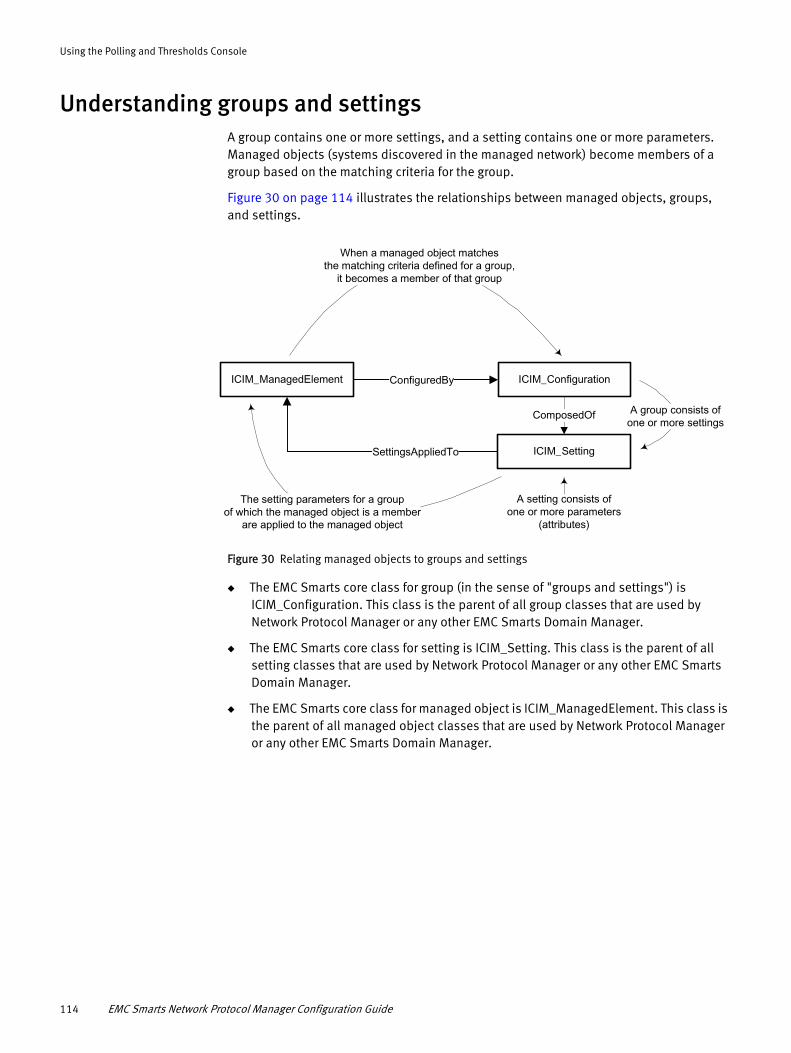
Using the Polling and Thresholds Console
Understanding groups and settingsA group contains one or more settings, and a setting contains one or more parameters. Managed objects (systems discovered in the managed network) become members of a group based on the matching criteria for the group.
Figure 30 on page 114 illustrates the relationships between managed objects, groups, and settings.
A setting consists ofone or more parameters
(attributes)
ConfiguredByICIM_ManagedElement
SettingsAppliedTo
ICIM_Configuration
ICIM_Setting
ComposedOf
When a managed object matchesthe matching criteria defined for a group,
it becomes a member of that group
A group consists ofone or more settings
The setting parameters for a groupof which the managed object is a member
are applied to the managed object
Figure 30 Relating managed objects to groups and settings
◆ The EMC Smarts core class for group (in the sense of "groups and settings") is ICIM_Configuration. This class is the parent of all group classes that are used by Network Protocol Manager or any other EMC Smarts Domain Manager.
◆ The EMC Smarts core class for setting is ICIM_Setting. This class is the parent of all setting classes that are used by Network Protocol Manager or any other EMC Smarts Domain Manager.
◆ The EMC Smarts core class for managed object is ICIM_ManagedElement. This class is the parent of all managed object classes that are used by Network Protocol Manager or any other EMC Smarts Domain Manager.
114 EMC Smarts Network Protocol Manager Configuration Guide

Using the Polling and Thresholds Console
Working with groups and settingsYou can use the Polling and Thresholds Console to perform any of the following tasks:
◆ “Assign managed objects to groups”
◆ “Modify the properties of a group”
◆ “Add or remove settings”
◆ “Modify the parameters of a setting”
◆ “Modify the priority of groups”
◆ “Edit matching criteria”
◆ “Create new groups”
Assign managed objects to groups
When Network Protocol Manager performs discovery, it automatically assigns each managed object to one or more groups based on the:
◆ Matching criteria for a group.
◆ Priority of a group, which determines membership when an object meets the matching criteria for more than one group within a particular group category.
A managed object may be a member of one and only one group within a particular group category.
Modify the properties of a group
A group’s matching criteria and priority determine which managed objects become members of the group.
When a group is selected in the left panel of the Polling and Thresholds Console, four tabs appear in the right panel of the console:
◆ Settings
◆ Priorities
◆ Matching Criteria
◆ Description
Modifying the properties in the Settings, Priorities, or Matching Criteria tab changes the configuration of the group.
When you finish editing the properties of a group, perform these steps:
1. Click the Apply button to save the changes.
2. Click the Reconfigure toolbar button, or select Group > Reconfigure, to make the configuration changes take effect.
Working with groups and settings 115

Using the Polling and Thresholds Console
Add or remove settings
A group’s settings determine what parameters are applied to the managed objects that are members of the group.
The Settings tab is divided into two sections:
◆ Current Settings
Lists the settings that are applied to the group.
◆ Available Settings
Lists additional available settings.
To add or remove a setting:
1. In the Settings tab, select a setting in the Available Settings list or in the Current Settings list.
2. Click Add to move an available setting to the Current Settings list, or click Remove to move a current setting to the Available Settings list.
3. Click the Apply button to save your changes.
4. Click the Reconfigure toolbar button to make your changes take effect.
Modify the parameters of a setting
The parameters of a setting are changed in one of two ways:
◆ By choosing a value from a drop-down menu.
◆ By entering a value in a Value field or adjusting a slider bar that represents a range of values.
Changing the parameters of a settingTo change the parameters of a setting:
1. In the left panel of the Polling and Thresholds Console, select the setting to display the parameters of the setting in the right panel of the console.
2. Change the value of a parameter by using one of the following methods:
For a drop-down menu, click the menu and select a value.
For a slider bar presentation, do one of the following:
• Type a value into the Value field and press Enter.
• Select the slider bar and drag its handle with the mouse to change the value or select the slider bar and use the arrow keys to move its handle to change the value.
3. Click the Apply button to save your changes.
4. Click the Reconfigure toolbar button to make your changes take effect.
116 EMC Smarts Network Protocol Manager Configuration Guide

Using the Polling and Thresholds Console
Restoring the default values of a settingTo restore the default values of a setting:
1. In the left panel of the Polling and Thresholds Console, select the setting to display the parameters of the setting in the right panel of the console.
2. Click Restore Defaults.
3. Click the Reconfigure toolbar button to make your changes take effect.
Modify the priority of groups
In any group category, you can arrange the groups in a high-to-low priority. A candidate member object is compared against the highest priority group first and becomes a member of the first group for which there is a criteria match.
The Priorities tab shows groups in the order of their priority, from highest to lowest.
To change the priority of a group:
1. In the Priorities tab, select the group for which you want to change the priority.
2. Click the up or down arrow to change its position relative to the other groups.
3. Click the Apply button to save your changes.
4. Click the Reconfigure toolbar button to make your changes take effect.
Edit matching criteria
A group’s matching criteria, which appear at the top of the Matching Criteria tab, are defined by using the attributes of the target class that is associated with the group. Each matching criterion has three fields: Name, Description, and Value.
◆ Name identifies the name of the target class attribute.
◆ Description is the description of the target class attribute.
◆ Value is the value of the target class attribute, which can be any combination of text, integers, and wildcards. The Value field for a matching criterion is not case-sensitive.
As an example of a matching criterion for target class UnitaryComputerSystem:
◆ If you specify "Router" for the Type attribute, only routers become members of the group.
◆ If you specify "R1*" for the Name attribute, only routers with names that begin with the string R1 become members of the group.
Appendix A, “Wildcard Patterns,” discusses wildcard syntax.
When a managed object matches a group’s target class and matches all of the attributes that are defined for the target class, the managed object becomes a member of the group.
Working with groups and settings 117

Using the Polling and Thresholds Console
Adding or removing matching criteriaTo add or remove matching criteria:
1. In the Disabled Criteria area of the Matching Criteria tab, select a matching criterion.
2. Click Enable to make the criterion active, moving it to the top of the Matching Criteria tab.
Use Disable to deactivate the criterion, moving it to the Disabled Criteria area of the Matching Criteria tab.
3. If you are adding a matching criterion, type a matching pattern in the Value field.
4. Click the Apply button to save your changes.
5. Click the Reconfigure toolbar button to make your changes take effect.
Changing the value of a matching criterionTo change the value of a matching criterion:
1. In the Matching Criteria tab, select the string in the Value field or double-click the Value field to highlight the current value.
2. Type the new value.
3. Click the Apply button to save your changes.
4. Click the Reconfigure toolbar button to make your changes take effect.
Network Protocol Manager compares a managed object against the matching criteria of the group with the highest priority. If an object matches all the criteria, Network Protocol Manager adds the object as a member of the group. Otherwise, Network Protocol Manager compares the object against the matching criteria of the group with the second highest priority, and so on.
Create new groups
You can create additional groups within any group category.
Creating a new group enables you to customize the settings for a group of managed objects. You can use two methods to create a new group:
◆ Copy an existing group. The new group contains the same settings and thresholds as the original group. Matching criteria are not copied.
◆ Create an empty group. The new group does not contain any settings or members. You must add settings and matching criteria, and set the priority of the new group.
After you create a new group, use the procedures described in this chapter to add settings and matching criteria and to set the priority of the new group.
118 EMC Smarts Network Protocol Manager Configuration Guide

Using the Polling and Thresholds Console
Copying an existing groupTo copy an existing group:
1. In the left panel of the Polling and Thresholds Console, right-click the group that you want to copy.
2. Select Copy from the pop-up menu to display the Copy Group dialog box.
3. In the dialog box, type a name and an optional description for the new group and click OK.
The new group contains the same settings and thresholds as the group you copied.
4. Edit the settings, matching criteria, and priority of the new group. Change the value of any parameters as necessary.
5. Click the Reconfigure toolbar button to make your changes take effect.
Creating an empty groupTo create an empty group:
1. In the left panel of the Polling and Thresholds Console, right-click the group for which you want to create a new group.
2. Select New Group from the pop-up menu to display the New Group dialog box.
3. In the dialog box, type a name and an optional description for the new group and click OK.
4. Add settings and matching criteria, and set the priority of the new group. Change the values of any thresholds or parameters as necessary.
5. Click the Reconfigure toolbar button to make your changes take effect.
Working with groups and settings 119

Using the Polling and Thresholds Console
120 EMC Smarts Network Protocol Manager Configuration Guide
CHAPTER 10Configuring Polling and Threshold Groups
This chapter describes how to configure polling and threshold groups for Network Protocol Manager. It consists of the following sections:
◆ Viewing the Polling and Thresholds tabs ............................................................... 122◆ Understanding SNMP polling, CLI polling, and thresholds ..................................... 124◆ Understanding polling groups, threshold groups, and settings.............................. 125◆ Modifying polling and threshold groups................................................................ 125◆ Default polling groups and settings....................................................................... 126◆ Default threshold groups and settings .................................................................. 137
Configuring Polling and Threshold Groups 121

Configuring Polling and Threshold Groups
Viewing the Polling and Thresholds tabsFigure 31 on page 122 shows the Polling tab of a Polling and Thresholds Console that is connected to a Network Protocol Manager for BGP named INCHARGE-BGP. The right panel of the console identifies “BGP SNMP Setting” as the setting for the default polling group “BGP.”
Polling group tree Polling group configuration window
Figure 31 Polling tab for Network Protocol Manager for BGP
Figure 32 on page 123 shows the Thresholds tab of the Polling and Thresholds Console that is connected to INCHARGE-BGP. The right panel of the console identifies “BGP Session Flapping” as the setting for the default threshold group “BGP Protocol Endpoints.”
122 EMC Smarts Network Protocol Manager Configuration Guide
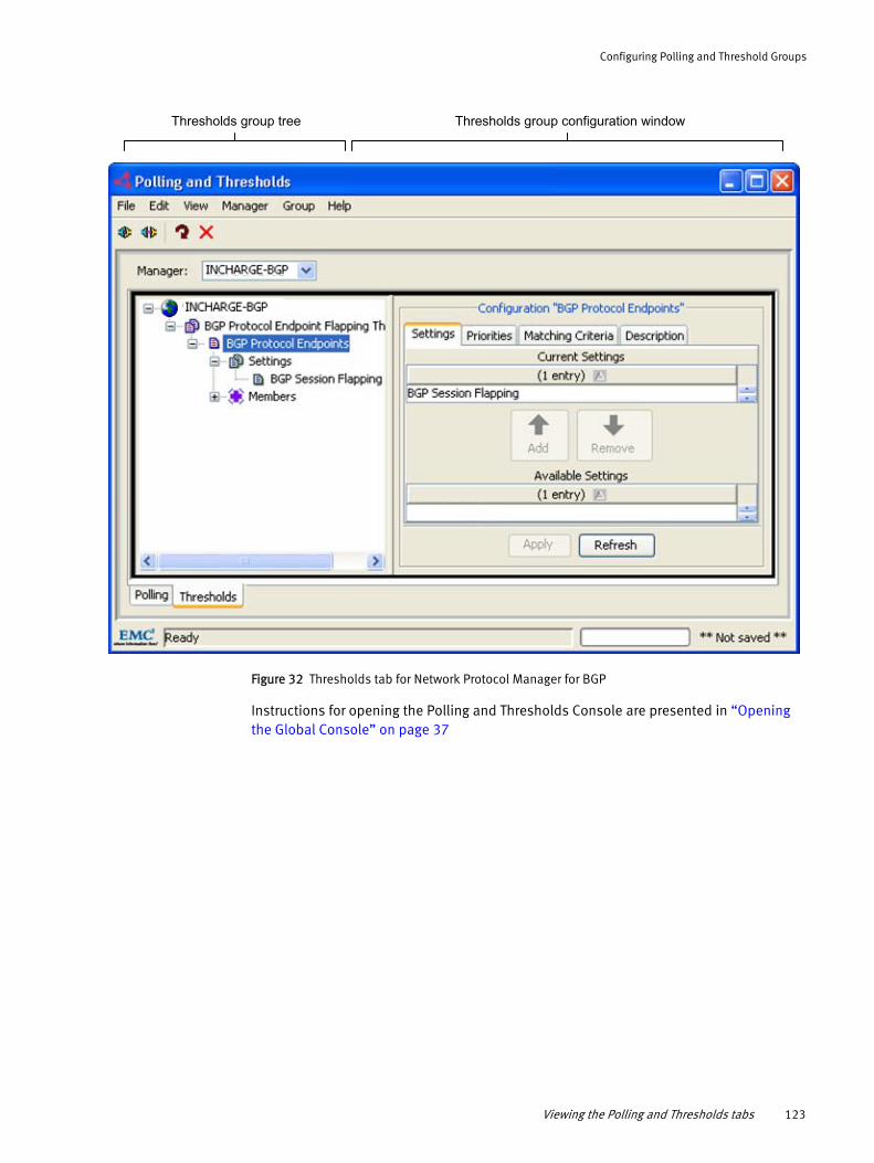
Configuring Polling and Threshold Groups
Thresholds group tree Thresholds group configuration window
Figure 32 Thresholds tab for Network Protocol Manager for BGP
Instructions for opening the Polling and Thresholds Console are presented in “Opening the Global Console” on page 37
Viewing the Polling and Thresholds tabs 123

Configuring Polling and Threshold Groups
Understanding SNMP polling, CLI polling, and thresholdsAs indicated in Figure 33 on page 124, Network Protocol Manager uses SNMP polling and CLI polling to monitor the managed network. The monitoring is controlled by polling-related and threshold-related objects that are created for Network Protocol Manager through the Polling and Thresholds Console.
IP network
EIGRP-enabled devicesBGP-enabled devices IS-IS-enabled devices OSPF-enabled devices
SNMP polling(Juniper & Cisco)
Network Protocol Managerfor EIGRP
CLI polling(Cisco)
Network Protocol Managerfor BGP
Network Protocol Managerfor IS-IS
(Configurepolling groups)
Network Protocol Managerfor OSPF
SNMP polling(Juniper)
CLI polling(Cisco)
SNMP polling(Juniper & Cisco)
Polling and Thresholds Console
Figure 33 SNMP-polling and CLI-polling configuration and operation
Network Protocol Manager monitors the health of the network by periodically sending SNMP polls or CLI polls to the routing-enabled devices to gather status information. The polled status information, in addition to the received BGP and OSPF trap messages, received BGP and OSPF syslog messages, and received IP Availability Manager status updates, serves as input to the correlation analysis function of Network Protocol Manager.
Appendix E, “SNMP Poller,” describes SNMP polling for correlation analysis.
The execution of SNMP polling requires SNMP read credentials, and the execution of CLI polling requires CLI login credentials. The SNMPv1, v2c, or v3 read credentials for a discovered device are stored in the attributes of the SNMPAgent object that is created for the device’s SNMP agent. The CLI login credentials for a discovered device are stored in a CLI device-access object. Network Protocol Manager imports SNMPAgent and CLI device-access objects from IP Availability Manager.
124 EMC Smarts Network Protocol Manager Configuration Guide

Configuring Polling and Threshold Groups
Understanding polling groups, threshold groups, and settingsUsing the Polling and Thresholds Console, you can customize the SNMP polling and CLI polling for Network Protocol Manager by modifying default polling groups, or by creating new polling groups. The polling groups periodically poll the managed routing-enabled routers to collect protocol session (adjacency) availability data.
Using the Polling and Thresholds Console, you can also customize the polling thresholds for Network Protocol Manager by modifying default threshold groups, or by creating new threshold groups.
Network Protocol Manager uses the settings in a polling or threshold group to assign parameters to the group.
Modifying polling and threshold groupsProcedures for modifying existing groups and creating new ones are given in “Working with groups and settings” on page 115.
When you finish editing the properties of a group, perform these steps:
1. Click the Apply button to save your configuration changes to an existing group object or to a newly created group object in the repository of Network Protocol Manager.
2. Click the Reconfigure toolbar button to make your configuration changes take effect.
When the reconfiguration completes, Network Protocol Manager imports the group object and saves the group object to its repository. Then, for a polling group object, Network Protocol Manager starts the polling that is configured for the object; for a threshold group object, Network Protocol Manager starts using the polling thresholds that are configured for the object.
Understanding polling groups, threshold groups, and settings 125

Configuring Polling and Threshold Groups
Default polling groups and settingsNetwork Protocol Manager provides five default polling groups. Table 12 on page 126 through Table 15 on page 126 list the default polling groups, their target classes, and their settings. The tables also identify the devices that are supported for the polling groups.
Table 12 Default Network Protocol Manager for BGP polling groups
Polling group Target class and matching criteria Settings Supported devices
• IsManaged = TRUE• SystemName = *
Table 13 Default Network Protocol Manager for EIGRP polling groups
Polling group Target class and matching criteria Settings Supported devices
• IsManaged = TRUE• SystemName = *
Table 14 Default Network Protocol Manager for IS-IS polling groups
Polling group Target class and matching criteria SettingsSupported devices
• IsManaged = TRUE• Vendor = CISCO
• IsManaged = TRUE• Vendor = JUNIPER
Table 15 Default Network Protocol Manager for OSPF polling groups
Polling group Target class and matching criteria Settings Supported devices
• IsManaged = TRUE• SystemName = *
Three things to note about Table 12 on page 126 through Table 15 on page 126:
◆ Only discovered objects that match the type and attribute values in the “Target class and matching criteria” column can become members of the group.
BGP BGPProtocolEndpoint with attributes: BGP SNMP Setting (default setting)BGP External Setting
Cisco and Juniper
IPv6 BGP HasIPv6=TRUE BGP_Cli_Setting Cisco and Juniper
EIGRP UnitaryComputerSystem with attributes:
EIGRP CLI Setting (default setting)EIGRP EXTERNAL Setting
Cisco
Cisco Devices UnitaryComputerSystem with attributes:
ISIS CISCO CLI Setting (default setting)ISIS EXTERNAL Setting
Cisco
Juniper Devices UnitaryComputerSystem with attributes:
ISIS JUNIPER SNMP Setting (default setting)ISIS EXTERNAL Setting
Juniper
OSPF OSPFInterface_Base with attributes: OSPF SNMP Setting (default setting)OSPF External Setting
Cisco and Juniper
126 EMC Smarts Network Protocol Manager Configuration Guide
Configuring Polling and Threshold Groups
◆ By default, all discovered objects that match the type and attribute values in the “Target class and matching criteria” column become members of the group.
You can specify matching criteria for a polling group to limit its membership, as explained in “Edit matching criteria” on page 117.
◆ The availability of a license for the EMC Smarts Adapter for Alcatel-Lucent 5620 SAM EMS (the Adapter)determines whether the following additional polling groups appear:
• 5620 SAM BGP
• 5620 SAM Devices
• 5620 SAM OSPF
The 5620 SAM polling groups appear only if the Adapter license is available. The 5620 SAM polling groups are described in the EMC Smarts Adapter for Alcatel-Lucent 5620 SAM EMS User Guide.
BGP polling group
The BGP default polling group is used by Network Protocol Manager for BGP to monitor the availability of BGP sessions. Network Protocol Manager for BGP monitors the availability by monitoring the BGPProtocolEndpoints that are discovered on Cisco or Juniper devices.
Because the standards-based BGP4 MIB (defined in RFC 1657) is used by both Cisco and Juniper devices, Network Protocol Manager for BGP uses SNMP to discover and monitor the BGP topology for Cisco and Juniper devices. The BGP polling group uses SNMP polling to monitor BGP sessions by monitoring the BGPProtocolEndpoints on the discovered devices.
The BGP polling group has a default setting and an optional setting:
◆ BGP SNMP Setting (default)
◆ BGP External Setting (optional)
The two settings are mutually exclusive, which means that only one or the other (but not both) can be specified for a BGP polling group at any given time.
BGP SNMP SettingThe BGP SNMP Setting determines the polling intervals that are used by Network Protocol Manager for BGP to monitor BGP protocol endpoints. Network Protocol Manager for BGP monitors the endpoints by probing the SNMP tables on the BGP-enabled devices.
Table 16 on page 128 lists the BGP SNMP Setting parameters.
Default polling groups and settings 127

Configuring Polling and Threshold Groups
Table 16 BGP SNMP Setting parameters and their values
Parameter Values Description
1. The Network Protocol Manager for BGP polling of BGP endpoint (BGPProtocolEndpoint) data.
2. The subsequent analysis of the polled data to determine the status of BGP sessions.
• 0.7 seconds for first retry• 1.4 seconds for second retry• 2.8 seconds for third retry
BGP External SettingThe BGP External Setting serves two purposes:
◆ Provides a means of testing the BGP endpoint instrumentation and analysis functionality of Network Protocol Manager for BGP.
◆ Provides a means for Network Protocol Manager for BGP to import BGP endpoint status updates from an EMC Smarts adapter, such as the EMC Smarts Adapter for Alcatel-Lucent 5620 SAM EMS.
Table 17 on page 129 lists the BGP External Setting parameters.
AnalysisMode ENABLED DISABLEDDefault: ENABLED
Enables or disables:
PollingInterval 30 to 3600 secondsDefault: 240 seconds
Sets the time between successive polls.
Retries 0 to 10 retriesDefault: 3
Sets the number of retry polls to perform when the initial poll fails.
Timeout 10 to 10000 millisecondsDefault: 700 milliseconds
Sets the amount of time to wait for the poll response before the first poll request times out. The timeout value doubles for each successive retry.For Timeout=700 msec (0.7 sec) and Retries=3:
128 EMC Smarts Network Protocol Manager Configuration Guide

Configuring Polling and Threshold Groups
Table 17 BGP External Setting parameters and their values
Parameter Values Description
• UNKNOWN is the default PeerState value before Network Protocol Manager for BGP sends SNMP polls to the device that is hosting the BGP endpoint.
• IDLE indicates that the BGP service for the BGP endpoint refuses all incoming BGP connections. No resources are allocated to the peer.
• CONNECT indicates that the BGP service for the BGP endpoint is waiting for the transport protocol connection to be completed.
• ACTIVE indicates that the BGP service for the BGP endpoint is trying to acquire a peer by initiating a transport protocol connection.
• OPENSENT indicates that the BGP service for the BGP endpoint is waiting for an OPEN message from its peer. When an OPEN message is received, the BGP service checks all fields for correctness.
• OPENCONFIRM indicates that the BGP service for the BGP endpoint is waiting for a KEEPALIVE or NOTIFICATION message. If the host device receives a KEEPALIVE message, the BGP service changes the state to Established.
• ESTABLISHED indicates that the BGP service for the BGP endpoint can exchange UPDATE, NOTIFICATION, and KEEPALIVE messages with its peer.
AnalysisMode ENABLED DISABLEDDefault: ENABLED
Enables or disables the availability analysis of the BGP endpoint (BGPProtocolEndpoint) data collected from an external source.
PeerState UNKNOWN IDLE CONNECT ACTIVE OPENSENT OPENCONFIRM ESTABLISHEDDefault: ESTABLISHED
Determines the initial peer state for the stored instrumentation objects that represent BGPProtocolEndpoints.
Default polling groups and settings 129
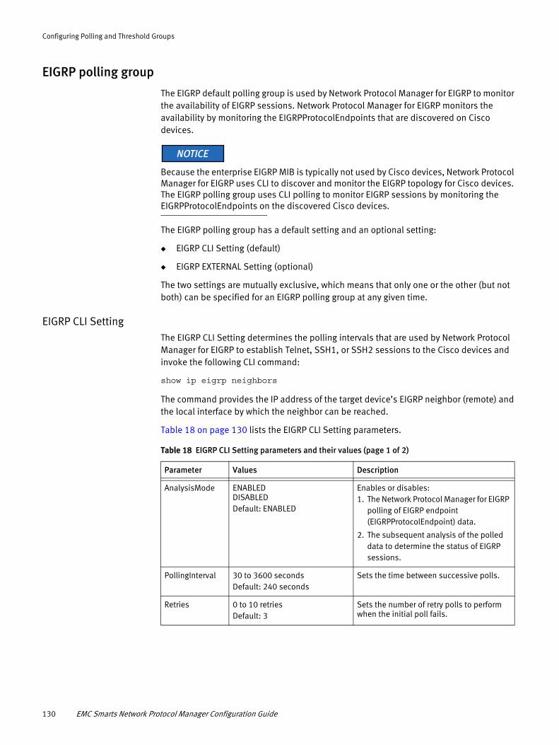
Configuring Polling and Threshold Groups
EIGRP polling group
The EIGRP default polling group is used by Network Protocol Manager for EIGRP to monitor the availability of EIGRP sessions. Network Protocol Manager for EIGRP monitors the availability by monitoring the EIGRPProtocolEndpoints that are discovered on Cisco devices.
Because the enterprise EIGRP MIB is typically not used by Cisco devices, Network Protocol Manager for EIGRP uses CLI to discover and monitor the EIGRP topology for Cisco devices. The EIGRP polling group uses CLI polling to monitor EIGRP sessions by monitoring the EIGRPProtocolEndpoints on the discovered Cisco devices.
The EIGRP polling group has a default setting and an optional setting:
◆ EIGRP CLI Setting (default)
◆ EIGRP EXTERNAL Setting (optional)
The two settings are mutually exclusive, which means that only one or the other (but not both) can be specified for an EIGRP polling group at any given time.
EIGRP CLI SettingThe EIGRP CLI Setting determines the polling intervals that are used by Network Protocol Manager for EIGRP to establish Telnet, SSH1, or SSH2 sessions to the Cisco devices and invoke the following CLI command:
show ip eigrp neighbors
The command provides the IP address of the target device’s EIGRP neighbor (remote) and the local interface by which the neighbor can be reached.
Table 18 on page 130 lists the EIGRP CLI Setting parameters.
Table 18 EIGRP CLI Setting parameters and their values (page 1 of 2)
Parameter Values Description
AnalysisMode ENABLED DISABLEDDefault: ENABLED
Enables or disables:1. The Network Protocol Manager for EIGRP
polling of EIGRP endpoint (EIGRPProtocolEndpoint) data.
2. The subsequent analysis of the polled data to determine the status of EIGRP sessions.
PollingInterval 30 to 3600 secondsDefault: 240 seconds
Sets the time between successive polls.
Retries 0 to 10 retriesDefault: 3
Sets the number of retry polls to perform when the initial poll fails.
130 EMC Smarts Network Protocol Manager Configuration Guide

Configuring Polling and Threshold Groups
EIGRP EXTERNAL SettingThe EIGRP EXTERNAL Setting serves two purposes:
◆ Provides a means of testing the EIGRP endpoint instrumentation and analysis functionality of Network Protocol Manager for EIGRP.
◆ Provides a means for Network Protocol Manager for EIGRP to import EIGRP endpoint status updates from an EMC Smarts adapter, such as the EMC Smarts Adapter for Alcatel-Lucent 5620 SAM EMS.
◆ Table 19 on page 131 lists the EIGRP EXTERNAL Setting parameters.
Table 19 EIGRP EXTERNAL Setting parameters and their values
Parameter Values Description
Cisco Devices polling group
The Cisco Devices default polling group is used by Network Protocol Manager for IS-IS to monitor the availability of IS-IS sessions (IS-IS adjacencies). Network Protocol Manager for IS-IS monitors the availability by monitoring the ISISInterfaces that are discovered on Cisco devices.
Because the standards-based IS-IS MIB (defined in RFC 1195) is not used by Cisco devices, Network Protocol Manager for IS-IS uses CLI to discover and monitor the IS-IS topology for Cisco devices. The Cisco Devices polling group uses CLI polling to monitor IS-IS sessions by monitoring the ISISInterfaces on the discovered Cisco devices.
Timeout 10 to 10000 millisecondsDefault: 700 milliseconds
Sets the amount of time to wait for the poll response before the first poll request times out. The timeout value doubles for each successive retry.For Timeout=700 msec (0.7 sec) and Retries=3:• 0.7 seconds for first retry• 1.4 seconds for second retry• 2.8 seconds for third retry
Table 18 EIGRP CLI Setting parameters and their values (page 2 of 2)
Parameter Values Description
eigrpPeerAdminStatus UNKNOWN UP DOWNDefault: UNKNOWN
Determines the initial peer administrative state for the stored instrumentation objects that represent EIGRPProtocolEndpoints.
PeerState UNKNOWN IDLE CONNECT ACTIVE OPENSENT OPENCONFIRM ESTABLISHEDDefault: UNKNOWN
Determines the initial peer state for the stored instrumentation objects that represent EIGRPProtocolEndpoints.
Default polling groups and settings 131

Configuring Polling and Threshold Groups
The Cisco Devices polling group has a default setting and an optional setting:
◆ ISIS CISCO CLI Setting (default)
◆ ISIS EXTERNAL Setting (optional)
The two settings are mutually exclusive, which means that only one or the other (but not both) can be specified for a Cisco Devices polling group at any given time.
ISIS CISCO CLI SettingThe ISIS CISCO CLI Setting determines the polling intervals that are used by Network Protocol Manager for IS-IS to establish Telnet, SSH1, or SSH2 sessions to the Cisco devices and invoke the following CLI command:
show clns neighbors detail
The command provides the target device’s CLNS neighbor interface connections (neighbor IP addresses).
Table 20 on page 132 lists the ISIS CISCO CLI Setting parameters.
Table 20 ISIS CISCO CLI Setting parameters and their values
Parameter Values Description
1. The Network Protocol Manager for IS-IS polling of IS-IS interface (ISISInterface) data.
2. The subsequent analysis of the polled data to determine the status of IS-IS sessions.
• 0.7 seconds for first retry• 1.4 seconds for second retry• 2.8 seconds for third retry
AnalysisMode ENABLED DISABLEDDefault: ENABLED
Enables or disables:
PollingInterval 30 to 3600 secondsDefault: 240 seconds
Sets the time between successive polls.
Retries 0 to 10 retriesDefault: 3
Sets the number of retry polls to perform when the initial poll fails.
Timeout 10 to 10000 millisecondsDefault: 700 milliseconds
Sets the amount of time to wait for the poll response before the first poll request times out. The timeout value doubles for each successive retry.For Timeout=700 msec (0.7 sec) and Retries=3:
132 EMC Smarts Network Protocol Manager Configuration Guide

Configuring Polling and Threshold Groups
ISIS EXTERNAL SettingThe ISIS EXTERNAL Setting serves two purposes:
◆ Provides a means of testing the IS-IS interface instrumentation and analysis functionality of Network Protocol Manager for IS-IS.
◆ Provides a means for Network Protocol Manager for IS-IS to import IS-IS interface status updates from an EMC Smarts EMC Smarts adapter, such as the EMC Smarts Adapter for Alcatel-Lucent 5620 SAM EMS.
Table 21 on page 133 lists the ISIS EXTERNAL Setting parameters.
Table 21 ISIS EXTERNAL Setting parameters and their values
Parameter Values Description
Juniper Devices polling group
The Juniper Devices default polling group is used by Network Protocol Manager for IS-IS to monitor the availability of IS-IS sessions (IS-IS adjacencies). Network Protocol Manager for IS-IS monitors the availability by monitoring the ISISInterfaces that are discovered on Juniper devices.
Because the standards-based IS-IS MIB (defined in RFC 1195) is used by Juniper devices, Network Protocol Manager for IS-IS uses SNMP to discover and monitor IS-IS topology for Juniper devices. The Juniper Devices polling group uses SNMP polling to monitor IS-IS sessions by monitoring the ISISInterfaces on the discovered Juniper devices.
The Juniper Devices polling group has a default setting and an optional setting:
◆ ISIS JUNIPER SNMP Setting (default)
◆ ISIS EXTERNAL Setting (optional)
The two settings are mutually exclusive, which means that only one or the other (but not both) can be specified for a Juniper Devices polling group at any given time.
ISIS JUNIPER SNMP SettingThe ISIS JUNIPER SNMP Setting determines the polling intervals that are used by Network Protocol Manager for IS-IS to monitor IS-IS interfaces. Network Protocol Manager for IS-IS monitors the interfaces by probing the SNMP tables on the ISIS-enabled devices.
The parameters for the ISIS JUNIPER SNMP Setting parameters are identical to the parameters for the ISIS CISCO CLI Setting parameters, which are listed in Table 20 on page 132.
NeighborState UNKNOWN UP INIT DOWN FAILEDDefault: UP
Determines the initial neighbor state for the stored instrumentation objects that represent IS-IS interfaces (ISISInterfaces).
Default polling groups and settings 133
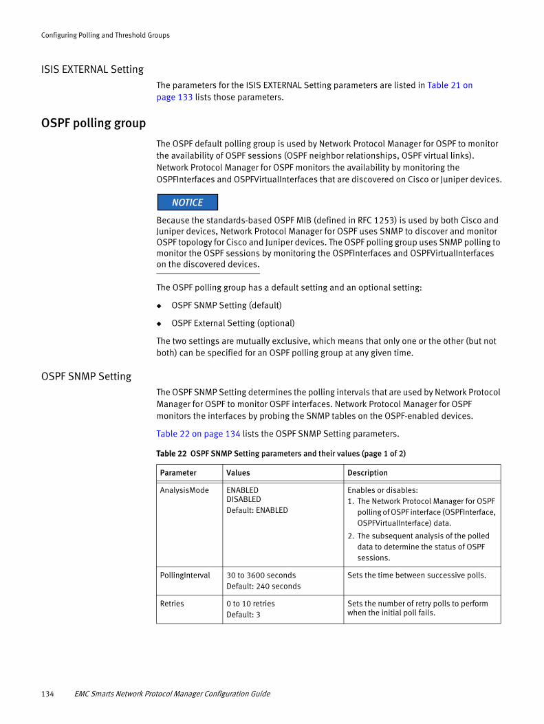
Configuring Polling and Threshold Groups
ISIS EXTERNAL SettingThe parameters for the ISIS EXTERNAL Setting parameters are listed in Table 21 on page 133 lists those parameters.
OSPF polling group
The OSPF default polling group is used by Network Protocol Manager for OSPF to monitor the availability of OSPF sessions (OSPF neighbor relationships, OSPF virtual links). Network Protocol Manager for OSPF monitors the availability by monitoring the OSPFInterfaces and OSPFVirtualInterfaces that are discovered on Cisco or Juniper devices.
Because the standards-based OSPF MIB (defined in RFC 1253) is used by both Cisco and Juniper devices, Network Protocol Manager for OSPF uses SNMP to discover and monitor OSPF topology for Cisco and Juniper devices. The OSPF polling group uses SNMP polling to monitor the OSPF sessions by monitoring the OSPFInterfaces and OSPFVirtualInterfaces on the discovered devices.
The OSPF polling group has a default setting and an optional setting:
◆ OSPF SNMP Setting (default)
◆ OSPF External Setting (optional)
The two settings are mutually exclusive, which means that only one or the other (but not both) can be specified for an OSPF polling group at any given time.
OSPF SNMP SettingThe OSPF SNMP Setting determines the polling intervals that are used by Network Protocol Manager for OSPF to monitor OSPF interfaces. Network Protocol Manager for OSPF monitors the interfaces by probing the SNMP tables on the OSPF-enabled devices.
Table 22 on page 134 lists the OSPF SNMP Setting parameters.
Table 22 OSPF SNMP Setting parameters and their values (page 1 of 2)
Parameter Values Description
AnalysisMode ENABLED DISABLEDDefault: ENABLED
Enables or disables:1. The Network Protocol Manager for OSPF
polling of OSPF interface (OSPFInterface, OSPFVirtualInterface) data.
2. The subsequent analysis of the polled data to determine the status of OSPF sessions.
PollingInterval 30 to 3600 secondsDefault: 240 seconds
Sets the time between successive polls.
Retries 0 to 10 retriesDefault: 3
Sets the number of retry polls to perform when the initial poll fails.
134 EMC Smarts Network Protocol Manager Configuration Guide
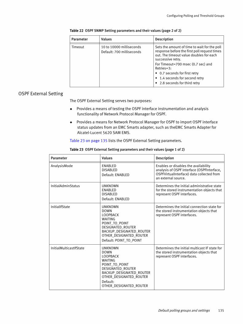
Configuring Polling and Threshold Groups
OSPF External SettingThe OSPF External Setting serves two purposes:
◆ Provides a means of testing the OSPF interface instrumentation and analysis functionality of Network Protocol Manager for OSPF.
◆ Provides a means for Network Protocol Manager for OSPF to import OSPF interface status updates from an EMC Smarts adapter, such as theEMC Smarts Adapter for Alcatel-Lucent 5620 SAM EMS.
Table 23 on page 135 lists the OSPF External Setting parameters.
Timeout 10 to 10000 millisecondsDefault: 700 milliseconds
Sets the amount of time to wait for the poll response before the first poll request times out. The timeout value doubles for each successive retry.For Timeout=700 msec (0.7 sec) and Retries=3:• 0.7 seconds for first retry• 1.4 seconds for second retry• 2.8 seconds for third retry
Table 22 OSPF SNMP Setting parameters and their values (page 2 of 2)
Parameter Values Description
Table 23 OSPF External Setting parameters and their values (page 1 of 2)
Parameter Values Description
AnalysisMode ENABLED DISABLEDDefault: ENABLED
Enables or disables the availability analysis of OSPF interface (OSPFInterface, OSPFVirtualInterface) data collected from an external source.
InitialAdminStatus UNKNOWN ENABLED DISABLEDDefault: ENABLED
Determines the initial administrative state for the stored instrumentation objects that represent OSPF interfaces.
InitialIfState UNKNOWN DOWN LOOPBACK WAITING POINT_TO_POINT DESIGNATED_ROUTER BACKUP_DESIGNATED_ROUTER OTHER_DESIGNATED_ROUTERDefault: POINT_TO_POINT
Determines the initial connection state for the stored instrumentation objects that represent OSPF interfaces.
InitialMulticastIfState UNKNOWN DOWN LOOPBACK WAITING POINT_TO_POINT DESIGNATED_ROUTER BACKUP_DESIGNATED_ROUTER OTHER_DESIGNATED_ROUTERDefault: OTHER_DESIGNATED_ROUTER
Determines the initial multicast IF state for the stored instrumentation objects that represent OSPF interfaces.
Default polling groups and settings 135

Configuring Polling and Threshold Groups
InitialNeighborState UNKNOWN DOWN ATTEMPT INIT TWO_WAY EXCHANGE_START EXCHANGE LOADING FULLDefault: FULL
Determines the initial neighbor state for the stored instrumentation objects that represent OSPF interfaces.
InitialNonMulticastIfState UNKNOWN DOWN LOOPBACK WAITING POINT_TO_POINT DESIGNATED_ROUTER BACKUP_DESIGNATED_ROUTER OTHER_DESIGNATED_ROUTERDefault: POINT_TO_POINT
Determines the initial non-multicast IF state for the stored instrumentation objects that represent OSPF interfaces.
InitialVirtualIfState UNKNOWN DOWN LOOPBACK WAITING POINT_TO_POINT DESIGNATED_ROUTER BACKUP_DESIGNATED_ROUTER OTHER_DESIGNATED_ROUTERDefault: POINT_TO_POINT
Determines the initial virtual state for the stored instrumentation objects that represent OSPF virtual interfaces.
InitialVirtualNeighborState UNKNOWN DOWN ATTEMPT INIT TWO_WAY EXCHANGE_START EXCHANGE LOADING FULLDefault: FULL
Determines the initial virtual neighbor state for the stored instrumentation objects that represent OSPF virtual interfaces.
Table 23 OSPF External Setting parameters and their values (page 2 of 2)
Parameter Values Description
136 EMC Smarts Network Protocol Manager Configuration Guide

Configuring Polling and Threshold Groups
Default threshold groups and settingsNetwork Protocol Manager provides one default threshold group. Table 24 on page 137 lists the default threshold group, its target class, and its setting. The table also identifies the devices that are supported for the threshold group.
Table 24 Default Network Protocol Manager for BGP threshold groups
Threshold group Target class and matching criteria Settings Supported devices
Two things to note about Table 24 on page 137:
◆ Only discovered objects that match the type and attribute values in the “Target class and matching criteria” column can become members of the group.
◆ By default, all discovered objects that match the type and attribute values in the “Target class and matching criteria” column become members of the group.
You can specify matching criteria for a threshold group to limit its membership, as explained in “Edit matching criteria” on page 117.
BGP Protocol Endpoints threshold group
The BGP Protocol Endpoints default threshold group is used by Network Protocol Manager for BGP to configure parameters for flapping analysis of BGP protocol endpoints. (A flapping endpoint is an endpoint that is continually going up and down.) Flapping analysis monitors SNMP bgpEstablished traps to identify a flapping endpoint, and then generates a Flapping event for the associated BGP session to report that the endpoint is flapping.
The EMC Smarts Network Protocol Manager for BGP User Guide provides information about how the Network Protocol Manager for BGP determines that a BGP protocol endpoint is flapping.
BGP Session Flapping settingThe BGP Session Flapping setting for the BGP Protocol Endpoints threshold group controls the flapping analysis. Table 25 on page 138 lists the BGP Session Flapping setting parameters.
BGP Protocol Endpoints BGPProtocolEndpoint (no specified attributes)
BGP Session Flapping
Cisco and Juniper
Default threshold groups and settings 137

Configuring Polling and Threshold Groups
Table 25 BGP Session Flapping setting parameters and their values
Parameter Default value Description
FLAP_Clear_Window 0 to any positive integer in minutesDefault: 60 minutes
Length of time to wait before clearing a Flapping event for a BGP session.The length of time should be set to a value that is greater than the value of the Trap_Time_Window. Exception: A value of 0 disables the clearing of Flapping events, meaning that Flapping events will remain active indefinitely.
Note: You can manually clear Flapping events at any time by setting the Trap_Count_Threshold or Trap_Time_Window parameter to 0 and then clicking the Reconfigure toolbar button. The Reconfigure toolbar button is described in Table 11 on page 113.
Trap_Count_Threshold 0 to any positive integerDefault: 0
Number of SNMP bgpEstablished traps that must be received within the Trap_Time_Window for Network Protocol Manager for BGP to consider a BGP protocol endpoint flapping.A value of 0 disables flapping analysis.
Trap_Time_Window 0 to any positive integer in secondsDefault: 30 seconds
Window of time within which the minimum number of bgpEstablished traps must be received for Network Protocol Manager for BGP to consider a BGP protocol endpoint flapping.When the number of received bgpEstablished traps equals or exceeds the Trap_Count_Threshold during this window of time, the endpoint is considered to be flapping.A value of 0 disables flapping analysis.
138 EMC Smarts Network Protocol Manager Configuration Guide

APPENDIX AWildcard Patterns
This appendix shows you how to use a wildcard pattern in a text field to match a number of objects instead of specifying each object by name. It consists of the following sections:
◆ Types of wildcard patterns .................................................................................... 140
Wildcard Patterns 139
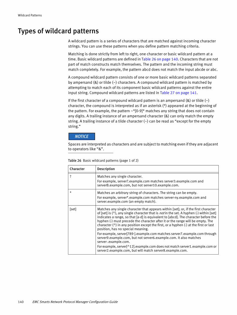
Wildcard Patterns
Types of wildcard patternsA wildcard pattern is a series of characters that are matched against incoming character strings. You can use these patterns when you define pattern matching criteria.
Matching is done strictly from left to right, one character or basic wildcard pattern at a time. Basic wildcard patterns are defined in Table 26 on page 140. Characters that are not part of match constructs match themselves. The pattern and the incoming string must match completely. For example, the pattern abcd does not match the input abcde or abc.
A compound wildcard pattern consists of one or more basic wildcard patterns separated by ampersand (&) or tilde (~) characters. A compound wildcard pattern is matched by attempting to match each of its component basic wildcard patterns against the entire input string. Compound wildcard patterns are listed in Table 27 on page 141.
If the first character of a compound wildcard pattern is an ampersand (&) or tilde (~) character, the compound is interpreted as if an asterisk (*) appeared at the beginning of the pattern. For example, the pattern ~*[0-9]* matches any string that does not contain any digits. A trailing instance of an ampersand character (&) can only match the empty string. A trailing instance of a tilde character (~) can be read as “except for the empty string.”
Spaces are interpreted as characters and are subject to matching even if they are adjacent to operators like “&”.
Table 26 Basic wildcard patterns (page 1 of 2)
Character Description
? Matches any single character. For example, server?.example.com matches server3.example.com and serverB.example.com, but not server10.example.com.
* Matches an arbitrary string of characters. The string can be empty. For example, server*.example.com matches server-ny.example.com and server.example.com (an empty match).
[set] Matches any single character that appears within [set]; or, if the first character of [set] is (^), any single character that is not in the set. A hyphen (-) within [set] indicates a range, so that [a-d] is equivalent to [abcd]. The character before the hyphen (-) must precede the character after it or the range will be empty. The character (^) in any position except the first, or a hyphen (-) at the first or last position, has no special meaning. For example, server[789-].example.com matches server7.example.com through server9.example.com, but not server6.example.com. It also matches server-.example.com.For example, server[^12].example.com does not match server1.example.com or server2.example.com, but will match server8.example.com.
140 EMC Smarts Network Protocol Manager Configuration Guide
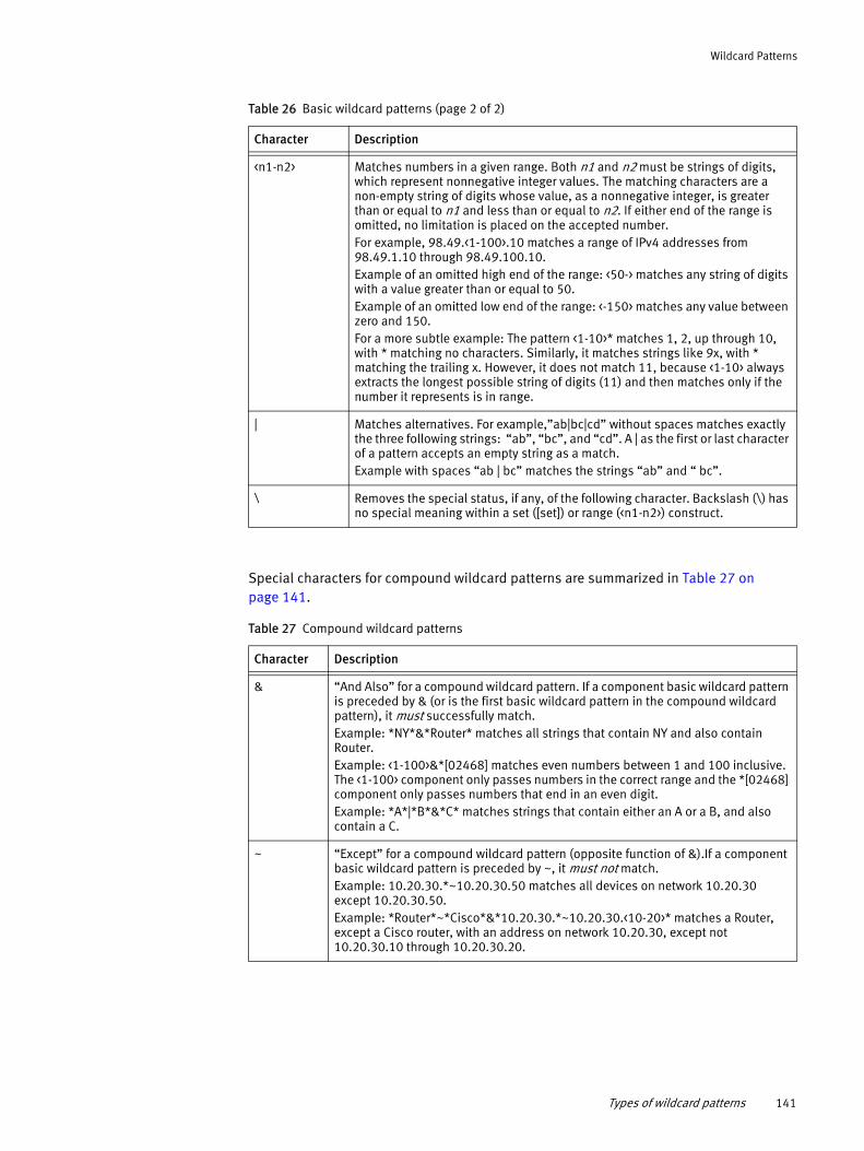
Wildcard Patterns
Special characters for compound wildcard patterns are summarized in Table 27 on page 141.
Table 27 Compound wildcard patterns
Character Description
<n1-n2> Matches numbers in a given range. Both n1 and n2 must be strings of digits, which represent nonnegative integer values. The matching characters are a non-empty string of digits whose value, as a nonnegative integer, is greater than or equal to n1 and less than or equal to n2. If either end of the range is omitted, no limitation is placed on the accepted number.For example, 98.49.<1-100>.10 matches a range of IPv4 addresses from 98.49.1.10 through 98.49.100.10. Example of an omitted high end of the range: <50-> matches any string of digits with a value greater than or equal to 50. Example of an omitted low end of the range: <-150> matches any value between zero and 150.For a more subtle example: The pattern <1-10>* matches 1, 2, up through 10, with * matching no characters. Similarly, it matches strings like 9x, with * matching the trailing x. However, it does not match 11, because <1-10> always extracts the longest possible string of digits (11) and then matches only if the number it represents is in range.
| Matches alternatives. For example,”ab|bc|cd” without spaces matches exactly the three following strings: “ab”, “bc”, and “cd”. A | as the first or last character of a pattern accepts an empty string as a match.Example with spaces “ab | bc” matches the strings “ab” and “ bc”.
\ Removes the special status, if any, of the following character. Backslash (\) has no special meaning within a set ([set]) or range (<n1-n2>) construct.
Table 26 Basic wildcard patterns (page 2 of 2)
Character Description
& “And Also” for a compound wildcard pattern. If a component basic wildcard pattern is preceded by & (or is the first basic wildcard pattern in the compound wildcard pattern), it must successfully match. Example: *NY*&*Router* matches all strings that contain NY and also contain Router. Example: <1-100>&*[02468] matches even numbers between 1 and 100 inclusive. The <1-100> component only passes numbers in the correct range and the *[02468] component only passes numbers that end in an even digit. Example: *A*|*B*&*C* matches strings that contain either an A or a B, and also contain a C.
~ “Except” for a compound wildcard pattern (opposite function of &).If a component basic wildcard pattern is preceded by ~, it must not match. Example: 10.20.30.*~10.20.30.50 matches all devices on network 10.20.30 except 10.20.30.50.Example: *Router*~*Cisco*&*10.20.30.*~10.20.30.<10-20>* matches a Router, except a Cisco router, with an address on network 10.20.30, except not 10.20.30.10 through 10.20.30.20.
Types of wildcard patterns 141

Wildcard Patterns
142 EMC Smarts Network Protocol Manager Configuration Guide
APPENDIX BMIBs Polled and Traps Processed
This appendix identifies the SNMP MIBs polled and the SNMP traps that are processed by Network Protocol Manager to monitor the discovered routing topology. It consists of the following sections:
◆ MIBs polled and traps processed for BGP monitoring ............................................ 144◆ MIBs polled and traps processed for OSPF monitoring .......................................... 147◆ MIBs polled for IS-IS monitoring............................................................................ 155
MIBs Polled and Traps Processed 143

MIBs Polled and Traps Processed
MIBs polled and traps processed for BGP monitoringNetwork Protocol Manager for BGP supports SNMPv1, v2c, and v3 for the BGP4 MIB objects and traps that are defined in RFC 1657. It reads the BGP4 MIB objects that are identified in the EMC Smarts Network Protocol Manager Discovery Guide to discover the following BGP objects:
◆ BGP autonomous systems
◆ BGP services
◆ BGP protocol endpoints
◆ BGP sessions
◆ BGP session groups
Network Protocol Manager for BGP then proceeds to monitor the discovered BGP objects by:
◆ Polling the BGP4 MIBs on the managed devices (described in “MIBs polled by BGP” on page 144).
◆ Processing BGP-related SNMP traps issued by the managed devices (optional and described in “Traps processed for BGP” on page 145).
◆ Processing BGP-related syslog messages issued by the managed devices (optional and described in “Syslog messages processed for BGP monitoring” on page 160).
MIBs polled by BGP
After discovering and creating the BGP topology objects in its repository, Network Protocol Manager for BGP monitors the status of the BGP objects by periodically establishing SNMP sessions to the managed devices and polling the BGP4 MIB objects that are listed in Table 28 on page 144.
Table 28 Instrumentation MIB objects polled by NPM for BGP (IPv4) (page 1 of 2)
MIB object OID Description Module
bgpPeerIdentifier .1.3.6.1.2.1.15.3.1.1 BGP Identifier of this entry’s BGP peer. BGP4 MIB
bgpPeerState .1.3.6.1.2.1.15.3.1.2 BGP peer connection state. BGP4 MIB
bgpPeerAdminStatus .1.3.6.1.2.1.15.3.1.3 BGP peer administrative status. BGP4 MIB
bgpPeerNegotiatedVersion .1.3.6.1.2.1.15.3.1.4 Negotiated version of BGP that is running between two BGP peers.
BGP4 MIB
bgpPeerLocalAddr .1.3.6.1.2.1.15.3.1.5 Local IP address of this entry’s BGP connection.
BGP4 MIB
bgpPeerLocalPort .1.3.6.1.2.1.15.3.1.6 Local port for the TCP connection between the BGP peers.
BGP4 MIB
bgpPeerRemotePort .1.3.6.1.2.1.15.3.1.8 Remote port for the TCP connection between the BGP peers.
BGP4 MIB
bgpPeerRemoteAS .1.3.6.1.2.1.15.3.1.9 Remote autonomous system (AS) number. BGP4 MIB
144 EMC Smarts Network Protocol Manager Configuration Guide
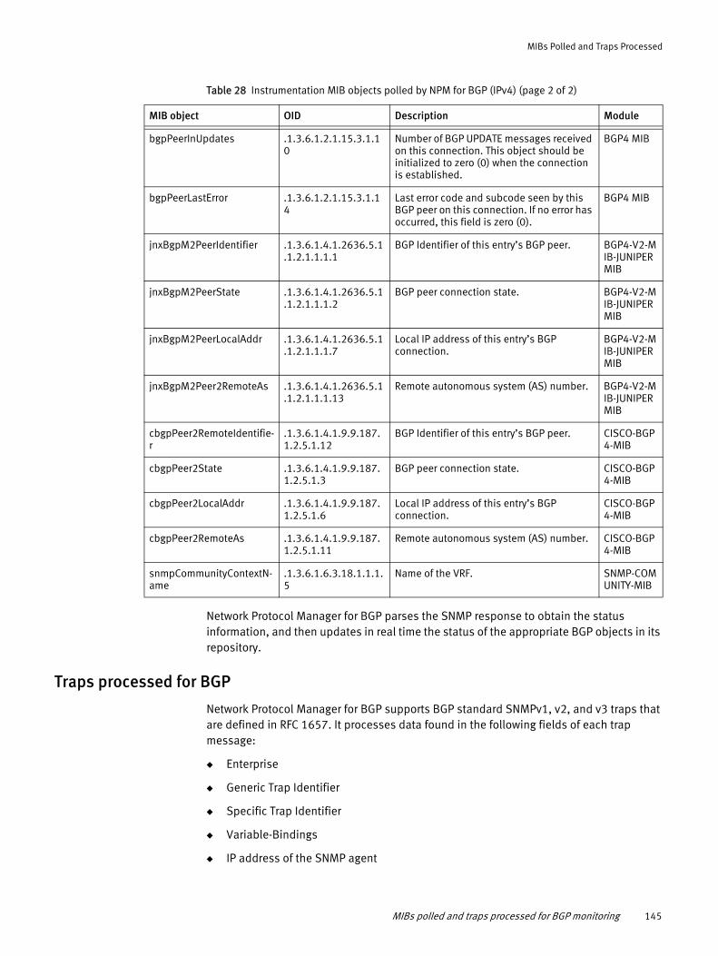
MIBs Polled and Traps Processed
Network Protocol Manager for BGP parses the SNMP response to obtain the status information, and then updates in real time the status of the appropriate BGP objects in its repository.
Traps processed for BGP
Network Protocol Manager for BGP supports BGP standard SNMPv1, v2, and v3 traps that are defined in RFC 1657. It processes data found in the following fields of each trap message:
◆ Enterprise
◆ Generic Trap Identifier
◆ Specific Trap Identifier
◆ Variable-Bindings
◆ IP address of the SNMP agent
bgpPeerInUpdates .1.3.6.1.2.1.15.3.1.10
Number of BGP UPDATE messages received on this connection. This object should be initialized to zero (0) when the connection is established.
BGP4 MIB
bgpPeerLastError .1.3.6.1.2.1.15.3.1.14
Last error code and subcode seen by this BGP peer on this connection. If no error has occurred, this field is zero (0).
BGP4 MIB
jnxBgpM2PeerIdentifier .1.3.6.1.4.1.2636.5.1.1.2.1.1.1.1
BGP Identifier of this entry’s BGP peer. BGP4-V2-MIB-JUNIPER MIB
jnxBgpM2PeerState .1.3.6.1.4.1.2636.5.1.1.2.1.1.1.2
BGP peer connection state. BGP4-V2-MIB-JUNIPER MIB
jnxBgpM2PeerLocalAddr .1.3.6.1.4.1.2636.5.1.1.2.1.1.1.7
Local IP address of this entry’s BGP connection.
BGP4-V2-MIB-JUNIPER MIB
jnxBgpM2Peer2RemoteAs .1.3.6.1.4.1.2636.5.1.1.2.1.1.1.13
Remote autonomous system (AS) number. BGP4-V2-MIB-JUNIPER MIB
cbgpPeer2RemoteIdentifie-r
.1.3.6.1.4.1.9.9.187.1.2.5.1.12
BGP Identifier of this entry’s BGP peer. CISCO-BGP4-MIB
cbgpPeer2State .1.3.6.1.4.1.9.9.187.1.2.5.1.3
BGP peer connection state. CISCO-BGP4-MIB
cbgpPeer2LocalAddr .1.3.6.1.4.1.9.9.187.1.2.5.1.6
Local IP address of this entry’s BGP connection.
CISCO-BGP4-MIB
cbgpPeer2RemoteAs .1.3.6.1.4.1.9.9.187.1.2.5.1.11
Remote autonomous system (AS) number. CISCO-BGP4-MIB
snmpCommunityContextN-ame
.1.3.6.1.6.3.18.1.1.1.5
Name of the VRF. SNMP-COMUNITY-MIB
Table 28 Instrumentation MIB objects polled by NPM for BGP (IPv4) (page 2 of 2)
MIB object OID Description Module
MIBs polled and traps processed for BGP monitoring 145
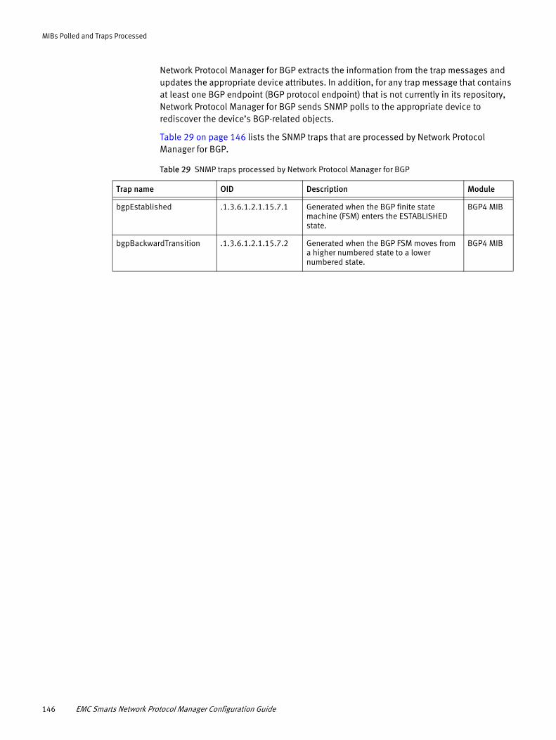
MIBs Polled and Traps Processed
Network Protocol Manager for BGP extracts the information from the trap messages and updates the appropriate device attributes. In addition, for any trap message that contains at least one BGP endpoint (BGP protocol endpoint) that is not currently in its repository, Network Protocol Manager for BGP sends SNMP polls to the appropriate device to rediscover the device’s BGP-related objects.
Table 29 on page 146 lists the SNMP traps that are processed by Network Protocol Manager for BGP.
Table 29 SNMP traps processed by Network Protocol Manager for BGP
Trap name OID Description Module
bgpEstablished .1.3.6.1.2.1.15.7.1 Generated when the BGP finite state machine (FSM) enters the ESTABLISHED state.
BGP4 MIB
bgpBackwardTransition .1.3.6.1.2.1.15.7.2 Generated when the BGP FSM moves from a higher numbered state to a lower numbered state.
BGP4 MIB
146 EMC Smarts Network Protocol Manager Configuration Guide
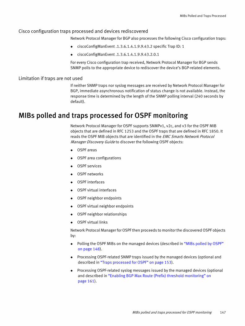
MIBs Polled and Traps Processed
Cisco configuration traps processed and devices rediscoveredNetwork Protocol Manager for BGP also processes the following Cisco configuration traps:
◆ ciscoConfigManEvent .1.3.6.1.4.1.9.9.43.2 specific Trap ID: 1
◆ ciscoConfigManEvent .1.3.6.1.4.1.9.9.43.2.0.1
For every Cisco configuration trap received, Network Protocol Manager for BGP sends SNMP polls to the appropriate device to rediscover the device’s BGP-related elements.
Limitation if traps are not usedIf neither SNMP traps nor syslog messages are received by Network Protocol Manager for BGP, immediate asynchronous notification of status change is not available. Instead, the response time is determined by the length of the SNMP polling interval (240 seconds by default).
MIBs polled and traps processed for OSPF monitoringNetwork Protocol Manager for OSPF supports SNMPv1, v2c, and v3 for the OSPF MIB objects that are defined in RFC 1253 and the OSPF traps that are defined in RFC 1850. It reads the OSPF MIB objects that are identified in the EMC Smarts Network Protocol Manager Discovery Guide to discover the following OSPF objects:
◆ OSPF areas
◆ OSPF area configurations
◆ OSPF services
◆ OSPF networks
◆ OSPF interfaces
◆ OSPF virtual interfaces
◆ OSPF neighbor endpoints
◆ OSPF virtual neighbor endpoints
◆ OSPF neighbor relationships
◆ OSPF virtual links
Network Protocol Manager for OSPF then proceeds to monitor the discovered OSPF objects by:
◆ Polling the OSPF MIBs on the managed devices (described in “MIBs polled by OSPF” on page 148).
◆ Processing OSPF-related SNMP traps issued by the managed devices (optional and described in “Traps processed for OSPF” on page 153).
◆ Processing OSPF-related syslog messages issued by the managed devices (optional and described in “Enabling BGP Max Route (Prefix) threshold monitoring” on page 161).
MIBs polled and traps processed for OSPF monitoring 147

MIBs Polled and Traps Processed
MIBs polled by OSPF
After discovering and creating the OSPF topology objects in its repository, Network Protocol Manager for OSPF monitors the status of the OSPF objects by periodically establishing SNMP sessions to the managed devices and polling the OSPF MIB objects that are listed in Table 30 on page 148.
Cisco devices that support RFC 5643 are supported for IPv6 discovery and monitoring.
Table 30 Instrumentation MIB objects polled by Network Protocol Manager for OSPF (page 1 of 5)
MIB object Object ID Description Module Protocol
ospfIfRtrPriority .1.3.6.1.2.1.14.7.1.6 Priority of this OSPF interface. In multi-access networks, used in the designated router (DR) election algorithm.
OSPF MIB IPv4
ospfIfHelloInterval .1.3.6.1.2.1.14.7.1.9 Length of time, in seconds, between the Hello packets that the router sends on this OSPF interface.
OSPF MIB IPv4
ospfIfRtrDeadInterval .1.3.6.1.2.1.14.7.1.10 Number of seconds that a router’s Hello packets have not been received before its neighbors declare the router down.
OSPF MIB IPv4
ospfIfAuthKey .1.3.6.1.2.1.14.7.1.16 Authentication key used to authenticate OSPF interfaces.
OSPF MIB IPv4
ospfIfAuthType .1.3.6.1.2.1.14.7.1.20 Authentication type specified for an OSPF interface.
OSPF MIB IPv4
ospfIfAdminStat .1.3.6.1.2.1.14.7.1.5 OSPF interface’s administrative status. The value formed on the interface is advertised as an internal route to some area.
OSPF MIB IPv4
ospfIfState .1.3.6.1.2.1.14.7.1.12 OSPF interface state. OSPF MIB IPv4
ospfIfDesignatedRouter .1.3.6.1.2.1.14.7.1.13 IP Address of the DR. OSPF MIB IPv4
ospfIfBackupDesignatedRouter .1.3.6.1.2.1.14.7.1.14 IP Address of the BDR. OSPF MIB IPv4
ospfIfEvents .1.3.6.1.2.1.14.7.1.15 Number of state changes or error events on this OSPF interface.
OSPF MIB IPv4
ospfVirtIfHelloInterval .1.3.6.1.2.1.14.9.1.5 Length of time, in seconds, between the Hello packets that the router sends on this OSPF virtual interface.
OSPF MIB IPv4
ospfVirtIfRtrDeadInterval .1.3.6.1.2.1.14.9.1.6 Number of seconds that a router’s Hello packets have not been received before its neighbors declare the router down.
OSPF MIB IPv4
ospfVirtIfState .1.3.6.1.2.1.14.9.1.7 OSPF virtual interface states. OSPF MIB IPv4
ospfVirtIfEvents .1.3.6.1.2.1.14.9.1.8 Number of state changes or error events on this virtual link.
OSPF MIB IPv4
148 EMC Smarts Network Protocol Manager Configuration Guide

MIBs Polled and Traps Processed
ospfVirtIfAuthKey .1.3.6.1.2.1.14.9.1.9 If authentication type is simplePassword, the device left-adjusts and zero-fills to 8 octets.
OSPF MIB IPv4
ospfVirtIfAuthType .1.3.6.1.2.1.14.9.1.11 Authentication type specified for a virtual interface.
OSPF MIB IPv4
ospfNbrRtrId .1.3.6.1.2.1.14.10.1.3 A 32-bit integer that uniquely identifies the neighboring router in the AS.
OSPF MIB IPv4
ospfNbrState .1.3.6.1.2.1.14.10.1.6 State of the relationship with this neighbor.
OSPF MIB IPv4
ospfNbrEvents .1.3.6.1.2.1.14.10.1.7 Number of times this neighbor relationship has changed state, or an error has occurred.
OSPF MIB IPv4
ospfNbrLsRetransQLen .1.3.6.1.2.1.14.10.1.8 Current length of the retransmission queue.
OSPF MIB IPv4
ospfVirtNbrIpAddr .1.3.6.1.2.1.14.11.1.3 IP address this virtual neighbor is using.
OSPF MIB IPv4
ospfVirtNbrState .1.3.6.1.2.1.14.11.1.5 State of the virtual neighbor relationship.
OSPF MIB IPv4
ospfVirtNbrEvents .1.3.6.1.2.1.14.11.1.6 Number of times this virtual link has changed its state, or an error has occurred.
OSPF MIB IPv4
ospfVirtNbrLsRetransQLen .1.3.6.1.2.1.14.11.1.7 Current length of the retransmission queue.
OSPF MIB IPv4
ospfv3AreaSummary .1.3.6.1.2.1.191.1.7.1.3 A 32-bit integer uniquely identifying the area to which the interface connects. Area ID 0 is used for the OSPFv3 backbone.
OSPF v3 MIB IPv6
ospfv3AdminStatus .1.3.6.1.2.1.191.1.1.2 The administrative status of OSPFv3 in the router. The value \enabled\ denotes that the OSPFv3 Process is active on at least one interface; \disabled\ disables it on all interfaces. This object is persistent, and when written, the entity SHOULD save the change to non-volatile storage.
OSPF v3 MIB IPv6
ospfv3IfAreaId .1.3.6.1.2.1.191.1.7.1.3 A 32-bit integer uniquely identifying the area to which the interface connects. Area ID 0 is used for the OSPFv3 backbone.
OSPF v3 MIB IPv6
ospfv3IfType .1.3.6.1.2.1.191.1.7.1.4 The OSPFv3 interface type. OSPF v3 MIB IPv6
Table 30 Instrumentation MIB objects polled by Network Protocol Manager for OSPF (page 2 of 5)
MIB object Object ID Description Module Protocol
MIBs polled and traps processed for OSPF monitoring 149

MIBs Polled and Traps Processed
ospfv3IfAdminStatus .1.3.6.1.2.1.191.1.7.1.5 The OSPFv3 interface\s administrative status. The value formed on the interface; the interface will be advertised as an internal route to some area. The value \disabled\ denotes that the interface is external to OSPFv3. Note that a value of \disabled\ for the object ospfv3AdminStatus will override a value of \enabled\ for the interface.
OSPF v3 MIB IPv6
ospfv3IfRtrPriority .1.3.6.1.2.1.191.1.7.1.6 The priority of this interface. Used in multi-access networks, this field is used in the designated-router election algorithm. The value 0 signifies that the router is not eligible to become the Designated Router on this particular network. In the event of a tie in this value, routers will use their Router ID as a tie breaker.
OSPF v3 MIB IPv6
ospfv3IfTransitDelay .1.3.6.1.2.1.191.1.7.1.7 The estimated number of seconds it takes to transmit a Link State Update packet over this interface. LSAs contained in the update packet must have their age incremented by this amount before transmission. This value should take into account the transmission and propagation delays of the interface.
OSPF MIB IPv6
ospfv3IfRetransInterval .1.3.6.1.2.1.191.1.7.1.8 The number of seconds between link state advertisement retransmissions for adjacencies belonging to this interface. This value is also used when retransmitting database description and Link State Request packets.
OSPF MIB IPv6
ospfv3IfPollInterval .1.3.6.1.2.1.191.1.7.1.11 The larger time interval, in seconds, between the Hello packets sent to an inactive, non-broadcast multi-access neighbor.
OSPF MIB IPv6
ospfv3IfState .1.3.6.1.2.1.191.1.7.1.12 The OSPFv3 interface state. An interface may be in standby state if there are multiple interfaces on the link and another interface is active. The interface may be in Down state if the underlying IPv6 interface is down or if the admin status is \disabled\ either globally or for the interface.
OSPF MIB IPv6
ospfv3IfDemand .1.3.6.1.2.1.191.1.7.1.17 Indicates whether Demand OSPFv3 procedures (Hello suppression to FULL neighbors and setting the DoNotAge flag on propagated LSAs) should be performed on this interface.
OSPF MIB IPv6
Table 30 Instrumentation MIB objects polled by Network Protocol Manager for OSPF (page 3 of 5)
MIB object Object ID Description Module Protocol
150 EMC Smarts Network Protocol Manager Configuration Guide

MIBs Polled and Traps Processed
ospfv3CfgNbrRowStatus .1.3.6.1.2.1.191.1.10.1.6 This object permits management of the table by facilitating actions such as row creation, construction, and destruction. The value of this object has no effect on whether other objects in this conceptual row can be modified.
OSPF MIB IPv6
ospfv3NbrAddress .1.3.6.1.2.1.191.1.9.1.5 The IPv6 address of the neighbor associated with the local link.
OSPF v3 MIB IPv6
ospfv3NbrState .1.3.6.1.2.1.191.1.9.1.8 The state of the relationship with this neighbor.
OSPF v3 MIB IPv6
ospfv3NbrIfId .1.3.6.1.2.1.191.1.9.1.12 The Interface ID that the neighbor advertises in its Hello packets on this link, that is, the neighbor\s local interface index.
OSPF v3 MIB IPv6
opsfv3NbrHelloSuppressed .1.3.6.1.2.1.191.1.9.1.11 Indicates whether Hellos are being suppressed to the neighbor.
OSPF v3 MIB IPv6
ospfv3VirtIfTransitDelay .1.3.6.1.2.1.191.1.8.1.5 The estimated number of seconds it takes to transmit a Link State Update packet over this interface.
OSPF v3 MIB IPv6
ospfv3VirtIfRetransInterval .1.3.6.1.2.1.191.1.8.1.6 The number of seconds between link state advertisement retransmissions for adjacencies belonging to this interface. This value is also used when retransmitting database description and Link State Request packets. This value should be well over the expected round-trip time.
OSPF v3 MIB IPv6
ospfv3VirtNbrIfIndex .1.3.6.1.2.1.191.1.11.1.3 The local Interface ID for the virtual link over which the neighbor can be reached.
OSPF v3 MIB IPv6
ospfv3VirtNbrAddress .1.3.6.1.2.1.191.1.11.1.6 The IPv6 address advertised by this virtual neighbor. It must be a global scope address.
OSPF v3 MIB IPv6
ospfv3VirtNbrLsRetransQLen .1.3.6.1.2.1.191.1.11.1.10 The current length of the retransmission queue.
OSPF v3 MIB IPv6
ospfv3VirtNbrHelloSuppressed .1.3.6.1.2.1.191.1.11.1.11 Indicates whether Hellos are being suppressed to the neighbor.
OSPF v3 MIB IPv6
ospfv3IfAdminStatus .1.3.6.1.2.1.191.1.7.1.5 The OSPFv3 interface\s administrative status. The value formed on the interface; the interface will be advertised as an internal route to some area. The value \disabled\ denotes that the interface is external to OSPFv3. Note that a value of \disabled\ for the object ospfv3AdminStatus will override a value of \enabled\ for the interface.
OSPF v3 MIB IPv6
Table 30 Instrumentation MIB objects polled by Network Protocol Manager for OSPF (page 4 of 5)
MIB object Object ID Description Module Protocol
MIBs polled and traps processed for OSPF monitoring 151
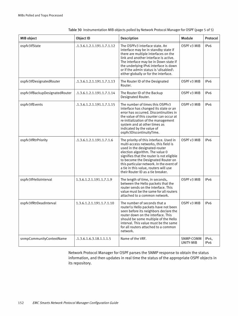
MIBs Polled and Traps Processed
Network Protocol Manager for OSPF parses the SNMP response to obtain the status information, and then updates in real time the status of the appropriate OSPF objects in its repository.
ospfv3IfState .1.3.6.1.2.1.191.1.7.1.12 The OSPFv3 interface state. An interface may be in standby state if there are multiple interfaces on the link and another interface is active. The interface may be in Down state if the underlying IPv6 interface is down or if the admin status is \disabled\ either globally or for the interface.
OSPF v3 MIB IPv6
ospfv3IfDesignatedRouter .1.3.6.1.2.1.191.1.7.1.13 The Router ID of the Designated Router.
OSPF v3 MIB IPv6
ospfv3IfBackupDesignatedRouter .1.3.6.1.2.1.191.1.7.1.14 The Router ID of the Backup Designated Router.
OSPF v3 MIB IPv6
ospfv3IfEvents .1.3.6.1.2.1.191.1.7.1.15 The number of times this OSPFv3 interface has changed its state or an error has occurred. Discontinuities in the value of this counter can occur at re-initialization of the management system and at other times as indicated by the value of ospfv3DiscontinuityTime.
OSPF v3 MIB IPv6
ospfv3IfRtrPriority .1.3.6.1.2.1.191.1.7.1.6 The priority of this interface. Used in multi-access networks, this field is used in the designated-router election algorithm. The value 0 signifies that the router is not eligible to become the Designated Router on this particular network. In the event of a tie in this value, routers will use their Router ID as a tie breaker.
OSPF v3 MIB IPv6
ospfv3IfHelloInterval 1.3.6.1.2.1.191.1.7.1.9 The length of time, in seconds, between the Hello packets that the router sends on the interface. This value must be the same for all routers attached to a common network.
OSPF v3 MIB IPv6
ospfv3IfRtrDeadInterval 1.3.6.1.2.1.191.1.7.1.10 The number of seconds that a router\s Hello packets have not been seen before its neighbors declare the router down on the interface. This should be some multiple of the Hello interval. This value must be the same for all routers attached to a common network.
OSPF v3 MIB IPv6
snmpCommunityContextName .1.3.6.1.6.3.18.1.1.1.5 Name of the VRF. SNMP-COMMUNITY-MIB
IPv4, IPv6
Table 30 Instrumentation MIB objects polled by Network Protocol Manager for OSPF (page 5 of 5)
MIB object Object ID Description Module Protocol
152 EMC Smarts Network Protocol Manager Configuration Guide

MIBs Polled and Traps Processed
Traps processed for OSPF
Network Protocol Manager for OSPF supports OSPF standard SNMPv1, v2, and v3 traps that are defined in RFC 1850. It processes data found in the following fields of each trap message:
◆ Enterprise
◆ Generic Trap Identifier
◆ Specific Trap Identifier
◆ Variable-Bindings
◆ IP address of the SNMP agent
Network Protocol Manager for OSPF extracts the information from the trap messages and updates the appropriate device attributes. In addition, for any trap message that contains at least one OSPF endpoint (OSPF neighbor endpoint, OSPF virtual neighbor endpoint) that is not currently in its repository, Network Protocol Manager for OSPF sends SNMP polls to the appropriate device to rediscover the device’s OSPF-related objects.
Table 31 on page 153 lists the SNMP traps that are processed by Network Protocol Manager for OSPF.
Table 31 SNMP traps processed by Network Protocol Manager for OSPF (page 1 of 2)
Trap name OID Description Module
ospfVirtIfStateChange .1.3.6.1.2.1.14.16.2.1 Signifies a change in the state of an OSPF virtual interface. This trap should be generated when the interface state regresses (for example, goes from Point-to-Point to Down) or progresses to a terminal state (that is, Point-to-Point).
OSPF MIB
ospfNbrStateChange .1.3.6.1.2.1.14.16.2.2 Signifies a change in the state of a non-virtual OSPF neighbor. This trap should be generated when the neighbor state regresses or progresses to a terminal state.
OSPF MIB
ospfVirtNbrStateChange .1.3.6.1.2.1.14.16.2.3 Signifies a change in the state of an OSPF virtual neighbor. This trap should be generated when the neighbor state regresses or progresses to a terminal state.
OSPF MIB
ospfIfConfigError .1.3.6.1.2.1.14.16.2.4 Signifies that a packet has been received on a non-virtual interface from a router whose configuration parameters conflict with this router’s configuration parameters.
OSPF MIB
ospfVirtIfConfigError .1.3.6.1.2.1.14.16.2.5 Signifies that a packet has been received on a virtual interface from a router whose configuration parameters conflict with this router’s configuration parameters.
OSPF MIB
ospfIfAuthFailure .1.3.6.1.2.1.14.16.2.6 Signifies that a packet has been received on a non-virtual interface from a router whose authentication key or authentication type conflicts with this router’s authentication key or authentication type.
OSPF MIB
MIBs polled and traps processed for OSPF monitoring 153

MIBs Polled and Traps Processed
Cisco configuration traps processed and devices rediscoveredNetwork Protocol Manager for OSPF also processes the following Cisco configuration traps:
◆ ciscoConfigManEvent .1.3.6.1.4.1.9.9.43.2 specific Trap ID: 1
◆ ciscoConfigManEvent .1.3.6.1.4.1.9.9.43.2.0.1
For every Cisco configuration trap received, Network Protocol Manager for OSPF sends SNMP polls to the appropriate device to rediscover the device’s OSPF-related objects.
ospfVirtIfAuthFailure .1.3.6.1.2.1.14.16.2.7 Signifies that a packet has been received on a virtual interface from a router whose authentication key or authentication type conflicts with this router’s authentication key or authentication type.
OSPF MIB
ospfIfRxBadPacket .1.3.6.1.2.1.14.16.2.8 Signifies that an OSPF packet has been received on a non-virtual interface that cannot be parsed.
OSPF MIB
ospfVirtIfRxBadPacket .1.3.6.1.2.1.14.16.2.9 Signifies that an OSPF packet has been received on a virtual interface that cannot be parsed.
OSPF MIB
ospfTxRetransmit .1.3.6.1.2.1.14.16.2.10 Signifies that an OSPF packet has been retransmitted on a non-virtual interface.
OSPF MIB
ospfVirtIfTxRetransmit .1.3.6.1.2.1.14.16.2.11 Signifies that an OSPF packet has been retransmitted on a virtual interface. All packets that may be retransmitted are associated with a link-state database entry.
OSPF MIB
ospfOriginateLsa .1.3.6.1.2.1.14.16.2.12 Signifies that a new link-state advertisement (LSA) has been originated by this router. This trap should not be invoked for simple refreshes of LSAs (which happens every 30 minutes), but instead is invoked only when an LSA is originated (or re-originated) due to a topology change.
OSPF MIB
ospfMaxAgeLsa .1.3.6.1.2.1.14.16.2.13 Signifies that one of the LSAs in the router’s link-state database has aged to MaxAge.
OSPF MIB
ospfLsdbOverflow .1.3.6.1.2.1.14.16.2.14 Signifies that the number of LSAs in the router’s link-state database has exceeded ospfExtLsdbLimit.
OSPF MIB
ospfLsdbApproachingOverflow .1.3.6.1.2.1.14.16.2.15 Signifies that the number of LSAs in the router’s link-state database has exceeded 90 percent of ospfExtLsdbLimit.
OSPF MIB
ospfIfStateChange .1.3.6.1.2.1.14.16.2.16 Signifies a change in the state of a non-virtual OSPF interface. This trap should be generated when the interface state regresses or progresses to a terminal state.
OSPF MIB
Table 31 SNMP traps processed by Network Protocol Manager for OSPF (page 2 of 2)
Trap name OID Description Module
154 EMC Smarts Network Protocol Manager Configuration Guide

MIBs Polled and Traps Processed
Limitation if traps are not usedIf neither SNMP traps nor syslog messages are received by Network Protocol Manager for OSPF, immediate asynchronous notification of status change is not available. Instead, the response time is determined by the length of the SNMP polling interval (240 seconds by default).
MIBs polled for IS-IS monitoringNetwork Protocol Manager for IS-IS supports the IS-IS MIB objects that are defined in RFC 1195 and in RFC 4444.
IS-IS MIB objects that are defined in RFC 1195
Network Protocol Manager for IS-IS supports SNMPv1, v2c, and v3 for the IS-IS MIB objects that are defined in RFC 1195. It does not receive or process SNMP traps.
Because the IS-IS MIB is used by Juniper devices but not by Cisco devices, Network Protocol Manager for IS-IS uses:
◆ SNMP discovery and SNMP polling to discover and monitor the IS-IS topology for Juniper devices.
◆ CLI discovery and CLI polling to discover and monitor the IS-IS topology for Cisco devices.
The CLI commands that are invoked for IS-IS discovery are identified in the EMC Smarts Network Protocol Manager Discovery Guide, and the CLI commands that are invoked for IS-IS monitoring are described in “CLI commands for IS-IS monitoring” on page 166.
For Juniper devices, Network Protocol Manager for IS-IS reads the IS-IS MIB objects that are identified in the EMC Smarts Network Protocol Manager Discovery Guide to discover the following IS-IS objects:
◆ IS-IS areas
◆ IS-IS services
◆ IS-IS networks
◆ IS-IS interfaces
◆ IS-IS neighbor endpoints
◆ IS-IS adjacencies
Network Protocol Manager for IS-IS then proceeds to monitor the discovered IS-IS objects by polling the IS-IS MIBs on the managed devices.
MIBs polled for IS-IS monitoring 155

MIBs Polled and Traps Processed
MIBs polled for IS-IS (RFC 1195)After discovering and creating the IS-IS topology objects in its repository, Network Protocol Manager for IS-IS monitors the status of the IS-IS objects by periodically establishing SNMP sessions to the Juniper devices and polling the IS-IS MIB objects that are listed in Table 32 on page 156.
Table 32 MIB object polled for instrumentation by Network Protocol Manager for IS-IS (page 1 of 2)
MIB object OID Description Module Protocol
isisISAdjState .1.3.6.1.3.37.1.5.1.1.2 The state of the adjacency:1 (DOWN)2 (INITIALIZING)3 (UP)4 (FAILED)
IS-IS MIB IPv4
ciiAreaAddr .1.3.6.1.4.1.9.10.118.1.1.3.1.1 The area address reported in a Level 1 link-state packet (LSP).
Cisco IS-IS MIB IPv6
ciiSysType .1.3.6.1.4.1.9.10.118.1.1.1.2 The level running on Intermediate System. This object follows the behavior of replaceOnlyWhileDisabled.
Cisco IS-IS MIB IPv6
ciiISAdjIPAddrAddress .1.3.6.1.4.1.9.10.118.1.6.3.1.3 The IP address received by the Intermediate System-to-Intermediate System Hello (IIH) Protocol data units (PDU) from the neighboring router.
Cisco IS-IS MIB IPv6
ciiCircIfIndex .1.3.6.1.4.1.9.10.118.1.3.2.1.2 Cisco IS-IS MIB IPv6
ciiSysID .1.3.6.1.4.1.9.10.118.1.1.1.3 The ID for this Intermediate System.This value is appended to the area addresses to form the Network Entity Titles.The object value derived is implementation- specific. Some implementations may automatically assign values and not permit an SNMP write, while others may require the value to be set manually.
Cisco IS-IS MIB IPv6
ciiISAdjNeighPriority .1.3.6.1.4.1.9.10.118.1.6.1.1.10 Priority of the neighboring Intermediate System for becoming the designated Intermediate System.
Cisco IS-IS MIB IPv6
ciiISAdjState .1.3.6.1.4.1.9.10.118.1.6.1.1.2 The state of the adjacency:1 (DOWN)2 (INITIALIZING)3 (UP)4 (FAILED)
Cisco IS-IS MIB IPv6
isisISAdjState .1.3.6.1.4.1.9.10.118.1.6.1.1.2 The state of the adjacency:1 (DOWN)2 (INITIALIZING)3 (UP)4 (FAILED)
Cisco IS-IS MIB IPv6
isisAreaAddr .1.3.6.1.2.1.138.1.1.3.1.1 The area address reported in a Level 1 LSP.
Juniper IS-IS MIB IPv6
156 EMC Smarts Network Protocol Manager Configuration Guide

MIBs Polled and Traps Processed
Network Protocol Manager for IS-IS parses the SNMP response to obtain the status information, and then updates in real time the status of the appropriate IS-IS objects in its repository.
IS-IS MIB objects that are defined in RFC 4444
The RFC 4444 support is only for IPv6 IS-IS.
ISIS RFC 4444 MIB support is verified and validated for devices only with IPv6 configured in them. For pure IPv4 devices with RFC 4444 ISIS-MIB support, the devices get discovered by the IP Manager but will not be listed as part of ISIS_TopologyCollection and hence the Network Protocol Manager for IS-IS will not discover the devices.
RFC 4444 followed devices (ISIS IPv6 MIB) are fully supported regardless of device vendors (Cisco and Juniper). Discovery and monitoring support is complete and the Network Protocol Manager for IS-IS is able to stitch topologies discovered using RFC 4444 MIBs.
Following is the complete OID information for RFC 4444:
#################################### ISIS-MIB - RFC 4444###################################
isisRouterLevel .1.3.6.1.2.1.138.1.1.6.1.2 The level at which the information about this Intermediate System is received.
Juniper IS-IS MIB IPv6
isisISAdjIPAddrAddress .1.3.6.1.2.1.138.1.6.3.1.3 The IP address received by the IIH PDUs from the neighboring router.The type of this address is determined by the value of the isisISAdjIPAddrType object.
Juniper IS-IS MIB IPv6
isisRouterSysID .1.3.6.1.2.1.138.1.1.6.1.1 The System ID of the Intermediate System.
Juniper IS-IS MIB IPv6
isisISAdjNeighPriority .1.3.6.1.2.1.138.1.6.1.1.10 Priority of the neighboring Intermediate System for becoming the designated Intermediate System.
Juniper IS-IS MIB IPv6
isisISAdjState .1.3.6.1.2.1.138.1.6.1.1.2 The state of the adjacency:1 (DOWN)2 (INITIALIZING)3 (UP)4 (FAILED)
Juniper IS-IS MIB IPv6
isisISAdjState .1.3.6.1.2.1.138.1.6.1.1.2 The state of the adjacency:1 (DOWN)2 (INITIALIZING)3 (UP)4 (FAILED)
Juniper IS-IS MIB IPv6
Table 32 MIB object polled for instrumentation by Network Protocol Manager for IS-IS (page 2 of 2)
MIB object OID Description Module Protocol
MIBs polled for IS-IS monitoring 157

MIBs Polled and Traps Processed
#isisAreaAddr{40, ".1.3.6.1.2.1.138.1.1.3.1.1"},
#isisSysLevelType{45, ".1.3.6.1.2.1.138.1.1.1.2"},
#isisISAdjIPAddrAddress{50, ".1.3.6.1.2.1.138.1.6.3.1.3"},
#isisCircIfIndex{51, ".1.3.6.1.2.1.138.1.3.2.1.2"},
#isisRouterSysID{55, ".1.3.6.1.2.1.138.1.1.1.3"},
#isisISAdjNeighPriority{60, ".1.3.6.1.2.1.138.1.6.1.1.10"},
#isisISAdjState{65, ".1.3.6.1.2.1.138.1.6.1.1.2"}
158 EMC Smarts Network Protocol Manager Configuration Guide
APPENDIX CSyslog Messages Processed
This appendix identifies the syslog messages that are processed by Network Protocol Manager to monitor the discovered routing topology. It consists of the following sections:
◆ Syslog messages processed for BGP monitoring ................................................... 160◆ Syslog messages processed for OSPF monitoring.................................................. 162
Syslog Messages Processed 159
Syslog Messages Processed
Syslog messages processed for BGP monitoringWhen syslog message processing is enabled for BGP, Network Protocol Manager for BGP obtains configuration, change, and BGP session status information for the managed devices from syslog messages that are sent by the devices. Network Protocol Manager for BGP extracts the information from the syslog messages and updates the attributes of the appropriate topology objects in its repository.
Processing syslog messages is recommended for BGP, but not required, because Network Protocol Manager for BGP polls the network for status information. However, if neither syslog messages nor SNMP traps are received by Network Protocol Manager for BGP, immediate asynchronous notification of status change is not available; instead, the response time is determined by the length of the SNMP polling interval (240 seconds by default).
Syslog message format
Network Protocol Manager for BGP reads and parses syslog messages that have the following format:
Time [Source] [Application]: %Facility[-Subfacility]-Severity-Mnemonic: Message Text
Sample syslog message
A sample syslog message that are processed by Network Protocol Manager for BGP is:
Jan 29 15:49:48.699: %BGP-3-NOTIFICATION: sent to neighbor 10.0.1.101 4/0 (hold time expired) 0 bytes
Syslog messages processed and actions taken
Table 33 on page 161 identifies which syslog messages are processed by Network Protocol Manager for BGP and what actions are taken by Network Protocol Manager for BGP. As indicated in Table 33 on page 161, candidate syslog messages have one of the following Facility-Mnemonic name combinations:
◆ BGP & NOTIFICATION
◆ BGP & ADJCHANGE
◆ BGP & MAXPFXEXCEED
◆ SYS & CONFIG_I
160 EMC Smarts Network Protocol Manager Configuration Guide

Syslog Messages Processed
Table 33 Syslog messages processed and actions taken
Facility name Mnemonic name Action
• Extracts the BGP configuration, change, and session status information from the message and updates the appropriate router attributes.
• If the message contains at least one BGP endpoint that is not currently in the topology database, Network Protocol Manager for BGP sends SNMP polls to the appropriate device to rediscover the device’s BGP-related objects.
• Parses the relevant syslog message originating from Cisco or Juniper devices after exceeding the threshold for receiving maximum routes from a neighbor over a BGP session. When the bMaxPrefixExceed setting for BGPProtocolEndPoint is set to TRUE as a result of threshold being crossed, a notification (PrefixThresholdCrossed) is generated.
• Does not extract any status information from the message.
• Sends SNMP polls to the appropriate device to rediscover the device’s BGP-related objects.
Enabling BGP Max Route (Prefix) threshold monitoringNetwork Protocol Manager for BGP monitors syslog messages from Cisco and Juniper devices to determine when the BGP Max Route (Prefix) threshold is exceeded. When Network Protocol Manager for BGP detects the threshold has been exceeded, the BGP application generates a PrefixThresholdCrossed notification for that BGP session and correlates it to the BGPsession “Down” notification.
Juniper syslog messages are not parsed for Facility-Mnemonic. Juniper syslog messages are processed based on the source device information in the message.
To receive the PrefixThresholdCrossed notification in the Notification Log Console, use sm_edit to modify the dxa-bgp.conf file available in the Service Assurance Manager deployment. Add the following lines:
sev BGPSession PrefixThresholdCrossed Operational 2sub BGPSession::.*::PrefixThresholdCrossed/e
For example:
./sm_edit conf/ics/dxa-bgp.conf
22 sev BGPSession Disconnected Operational 323 sev BGPSession Flapping Operational 324 sev BGPSessionGroup Impacted Impacted 325 sev BGPSession PrefixThresholdCrossed Operational 2...56 # Send events List Subscription 57 sub .*::.*::.*/p 58 sub BGPSession::.*:Disconnected/e 59 sub BGPSession::.*::Flapping/e 60 sub BGPSessionGroup::.*::Impacted/e
BGP NOTIFICATION
BGP ADJCHANGE
BGP MAXPFXEXCEED
SYS CONFIG_I
Syslog messages processed for BGP monitoring 161

Syslog Messages Processed
61 sub RedundancyGroup::.*::.*/e 62 sub BGPSession::.*:PrefixThresholdCrossed/e 63 #COMPUTER SYSTEMS
The PrefixThresholdCrossed notification clears after a configured time interval, SysCleanTime, is reached. SysCleanTime default value is 86,400 seconds (24 hours). SysCleanTime is specified in <BASEDIR>/conf/bgp/bgp.conf and the value may be changed in the Domain Manager Administration Console.
Syslog messages processed for OSPF monitoringWhen syslog message processing is enabled for OSPF, Network Protocol Manager for OSPF obtains configuration, change, and OSPF adjacency status information for the managed devices from syslog messages that are sent by the devices. Network Protocol Manager for OSPF extracts the information from the syslog messages and updates the attributes of the appropriate topology objects in its repository.
Processing syslog messages is recommended for OSPF, but not required, because Network Protocol Manager for OSPF polls the network for status information. However, if neither syslog messages nor SNMP traps are received by Network Protocol Manager for OSPF, immediate asynchronous notification of status change is not available; instead, the response time is determined by the length of the SNMP polling interval (240 seconds by default).
Syslog message format
Network Protocol Manager for OSPF reads and parses syslog messages that have the following format:
Time [Source] [Application]: %Facility[-Subfacility]-Severity-Mnemonic: Message Text
Network Protocol Manager for OSPF also reads and parses Mismatch Authentication Key syslog messages sent by Cisco devices to detect Message Digest 5 (MD5) authentication failures.
Sample syslog messages
Sample syslog messages that are processed by Network Protocol Manager for OSPF are:
Jan 29 14:11:47.566: %OSPF-5-ADJCHG: Process 100, Nbr 10.0.0.110 on XTagATM51212 from LOADING to FULL, Loading Done
Sep 11 18:27:23 ins-2.smarts.com 74: 3d00h: OSPF: Rcv pkt from 172.16.2.1, Ethernet0/0 : Mismatch Authentication Key - Message Digest Key 1
The message text portion of a syslog message is sometimes quite lengthy. For example, the message text portion of an OSPF-related syslog message might look like this:
Process 100, Nbr 10.0.0.100 on Switch1.1 from FULL to DOWN, Neighbor Down: Interface down or detached Process 100, Nbr 10.0.0.110 on XTagATM51212 from FULL to DOWN, Neighbor Down: Dead timer expired Process 100, Nbr 10.0.0.110 on XTagATM51212 from LOADING to FULL, Loading Done
162 EMC Smarts Network Protocol Manager Configuration Guide
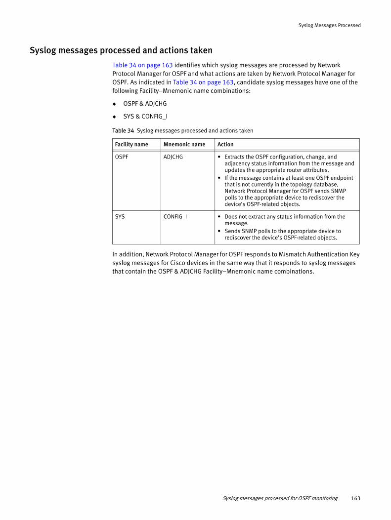
Syslog Messages Processed
Syslog messages processed and actions taken
Table 34 on page 163 identifies which syslog messages are processed by Network Protocol Manager for OSPF and what actions are taken by Network Protocol Manager for OSPF. As indicated in Table 34 on page 163, candidate syslog messages have one of the following Facility–Mnemonic name combinations:
◆ OSPF & ADJCHG
◆ SYS & CONFIG_I
Table 34 Syslog messages processed and actions taken
Facility name Mnemonic name Action
• Extracts the OSPF configuration, change, and adjacency status information from the message and updates the appropriate router attributes.
• If the message contains at least one OSPF endpoint that is not currently in the topology database, Network Protocol Manager for OSPF sends SNMP polls to the appropriate device to rediscover the device’s OSPF-related objects.
• Does not extract any status information from the message.
• Sends SNMP polls to the appropriate device to rediscover the device’s OSPF-related objects.
In addition, Network Protocol Manager for OSPF responds to Mismatch Authentication Key syslog messages for Cisco devices in the same way that it responds to syslog messages that contain the OSPF & ADJCHG Facility–Mnemonic name combinations.
OSPF ADJCHG
SYS CONFIG_I
Syslog messages processed for OSPF monitoring 163

Syslog Messages Processed
164 EMC Smarts Network Protocol Manager Configuration Guide
APPENDIX DCLI Commands for Monitoring
This appendix identifies the CLI commands that are invoked by Network Protocol Manager to monitor the discovered routing topology. It consists of the following sections:
◆ CLI commands for EIGRP monitoring...................................................................... 166◆ CLI commands for IS-IS monitoring ....................................................................... 166◆ CLI commands for BGP IPv6 discovery and monitoring of Cisco devices................. 167◆ CLI commands for BGP IPv6 discovery and monitoring of Juniper devices .............. 168
CLI Commands for Monitoring 165

CLI Commands for Monitoring
CLI commands for EIGRP monitoringBecause the enterprise EIGRP MIB is typically not used by Cisco devices, Network Protocol Manager for EIGRP uses CLI discovery and CLI polling to discover and monitor EIGRP topology. The CLI commands that are invoked for EIGRP discovery are identified in the EMC Smarts Network Protocol Manager Discovery Guide, and the CLI commands that are invoked for EIGRP monitoring are identified in this section.
Network Protocol Manager for EIGRP establishes Telnet, SSH1, or SSH2 sessions to the Cisco devices and invokes the following CLI command:
show ip eigrp neighborsandsh ip eigrp vrf * neighbors
The command provides the IP address of the target device’s EIGRP neighbor (remote) and the local interface by which the neighbor can be reached.
CLI commands for IS-IS monitoringBecause the standards-based IS-IS MIB is used by Juniper devices but not by Cisco devices, Network Protocol Manager for IS-IS uses:
◆ SNMP discovery and SNMP polling to discover and monitor the IS-IS topology for Juniper devices.
◆ CLI discovery and CLI polling to discover and monitor the IS-IS topology for Cisco devices.
The CLI commands that are invoked for IS-IS discovery are identified in the EMC Smarts Network Protocol Manager Discovery Guide, and the CLI commands that are invoked for IS-IS monitoring are described in this section.
Network Protocol Manager for IS-IS establishes Telnet, SSH1, or SSH2 sessions to the Cisco devices and invokes the following CLI command:
show clns neighbors detail
The command provides the target device’s CLNS neighbor interface connections (neighbor IP addresses).
166 EMC Smarts Network Protocol Manager Configuration Guide

CLI Commands for Monitoring
CLI commands for BGP IPv6 discovery and monitoring of Cisco devices
Command
show bgp ipv6 unicast summary
Ensure correct configuration of the BGP connection in order to get a response to this command.
When the router configuration is modified so that changes can be made to the IPv6 configuration, then the router does not return a result for this command. As a result, any information pertaining to IPv6 configuration change cannot be obtained.
◆ If the configuration change affects the status of the connection and the CLI response can be retrieved, then the status of the Cisco IPv6 BGP configuration can updated.
◆ If the configuration change does not return any response to the CLI command, then the BGP session will be shown as disconnected (with either BGPSesssion::Down or BGPService::Down as appropriate) and no further processing of notifications take place.
Sample output
dev-7604_lwqgw016#show bgp ipv6 unicast summaryBGP router identifier 192.168.216.240, local AS number 1097BGP table version is 13, main routing table version 132 network entries using 336 bytes of memory2 path entries using 208 bytes of memory2/2 BGP path/bestpath attribute entries using 272 bytes of memory0 BGP route-map cache entries using 0 bytes of memory0 BGP filter-list cache entries using 0 bytes of memoryBGP using 816 total bytes of memoryBGP activity 12/8 prefixes, 19/14 paths, scan interval 60 secs
Neighbor V AS MsgRcvd MsgSent TblVer InQ OutQ Up/Down State/PfxRcd
2001::2 4 1097 3180 3183 13 0 0 2d00h 1
dev-7604_lwqgw016#exit
CLI commands for BGP IPv6 discovery and monitoring of Cisco devices 167

CLI Commands for Monitoring
CLI commands for BGP IPv6 discovery and monitoring of Juniper devices
Command
show bgp summary
Sample output
Groups: 3 Peers: 9 Down peers: 2Table Tot Paths Act Paths Suppressed History Damp State Pendinginet.0 79 39 0 0 0 0bgp.l3vpn.0 0 0 0 0 0 0inet6.0 1 0 0 0 0 0bgp.l2vpn.0 0 0 0 0 0 0inet.2 0 0 0 0 0 0Peer AS InPkt OutPkt OutQ Flaps Last Up/Dwn
State|#Active/Received/Accepted/Damped...192.168.4.1 1097 0 0 0 0 7w6d9h Active192.168.7.1 1097 131344 146791 0 1 6w4d16h Establ inet.0: 20/42/38/0192.168.8.1 1097 1971 2197 0 5 16:44:53 Establ inet.0: 10/13/13/0192.168.10.1 8888 0 0 0 0 7w6d9h Active192.168.18.1 8888 175922 174285 0 0 7w6d8h Establ inet.0: 0/0/0/0192.168.77.8 8888 175385 174287 0 0 7w6d9h Establ inet.0: 0/0/0/0192.168.77.18 8888 159555 174292 0 0 7w6d9h Establ inet.0: 0/0/0/0192.168.167.1 1097 131376 146792 0 1 6w4d16h Establ inet.0: 9/24/24/02000::2 8888 175388 174078 0 0 7w6d9h Establ inet6.0: 0/1/1/0
168 EMC Smarts Network Protocol Manager Configuration Guide

APPENDIX ESNMP Poller
This appendix describes the SNMP poller used by Network Protocol Manager to obtain status updates for its correlation analysis. It consists of the following sections:
◆ SNMP polling overview ......................................................................................... 170◆ SNMP poller operation .......................................................................................... 170
SNMP Poller 169
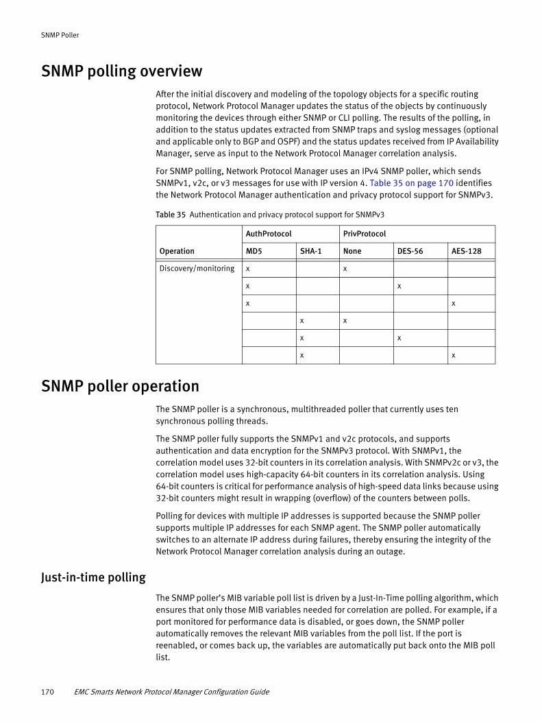
SNMP Poller
SNMP polling overviewAfter the initial discovery and modeling of the topology objects for a specific routing protocol, Network Protocol Manager updates the status of the objects by continuously monitoring the devices through either SNMP or CLI polling. The results of the polling, in addition to the status updates extracted from SNMP traps and syslog messages (optional and applicable only to BGP and OSPF) and the status updates received from IP Availability Manager, serve as input to the Network Protocol Manager correlation analysis.
For SNMP polling, Network Protocol Manager uses an IPv4 SNMP poller, which sends SNMPv1, v2c, or v3 messages for use with IP version 4. Table 35 on page 170 identifies the Network Protocol Manager authentication and privacy protocol support for SNMPv3.
Table 35 Authentication and privacy protocol support for SNMPv3
Operation
AuthProtocol PrivProtocol
MD5 SHA-1 None DES-56 AES-128
SNMP poller operationThe SNMP poller is a synchronous, multithreaded poller that currently uses ten synchronous polling threads.
The SNMP poller fully supports the SNMPv1 and v2c protocols, and supports authentication and data encryption for the SNMPv3 protocol. With SNMPv1, the correlation model uses 32-bit counters in its correlation analysis. With SNMPv2c or v3, the correlation model uses high-capacity 64-bit counters in its correlation analysis. Using 64-bit counters is critical for performance analysis of high-speed data links because using 32-bit counters might result in wrapping (overflow) of the counters between polls.
Polling for devices with multiple IP addresses is supported because the SNMP poller supports multiple IP addresses for each SNMP agent. The SNMP poller automatically switches to an alternate IP address during failures, thereby ensuring the integrity of the Network Protocol Manager correlation analysis during an outage.
Just-in-time polling
The SNMP poller’s MIB variable poll list is driven by a Just-In-Time polling algorithm, which ensures that only those MIB variables needed for correlation are polled. For example, if a port monitored for performance data is disabled, or goes down, the SNMP poller automatically removes the relevant MIB variables from the poll list. If the port is reenabled, or comes back up, the variables are automatically put back onto the MIB poll list.
Discovery/monitoring x x
x x
x x
x x
x x
x x
170 EMC Smarts Network Protocol Manager Configuration Guide
SNMP Poller
Request-consolidation polling
Issuing a single SNMP GET request that requests 10 variables is more efficient than issuing 10 GET requests each requesting a single variable. The SNMP poller consolidates as many variables as possible into a single SNMP GET request. The consolidation is not restricted to variables from the same SNMP table. Polling consolidation continually adapts to changes in the MIB variable poll list.
Upon encountering a non-fatal error during polling consolidation, the SNMP poller responds differently to an SNMPv1 agent than to an SNMPv2c or v3 agent for the following reason: Where an SNMPv1 agent stops processing a request upon encountering an error, an SNMPv2c or v3 agent continues processing a request upon encountering an error. An SNMPv2c or v3 agent handles errors on a per-OID basis.
If a non-fatal error is encountered by an SNMPv1 agent during a GET request that is seeking multiple variables, the SNMP poller suspends the polling of the affected variable because continuing to poll that variable would require the resending of the remainder of the request after receiving the error. An example of an affected variable is one that has become unavailable due to a configuration change. Of course, the SNMP poller continues to poll the unaffected variables. This behavior enables the SNMP poller to operate efficiently with an SNMPv1 agent during unexpected changes to a device’s configuration.
In contrast, if a non-fatal error is encountered by an SNMPv2c or v3 agent during a GET request that is seeking multiple variables, the SNMP poller continues the polling of the affected variable as well as the unaffected variables.
SNMP poller operation 171

SNMP Poller
172 EMC Smarts Network Protocol Manager Configuration Guide

APPENDIX FNPM dump instrumentation utility
This appendix describes the Network Protocol Manager dump instrumentation utility used for troubleshooting. It consists of the following sections:
◆ Network Protocol Manager dump instrumentation utility ....................................... 174◆ Invoking the NPM dump instrumentation utility..................................................... 174
NPM dump instrumentation utility 173
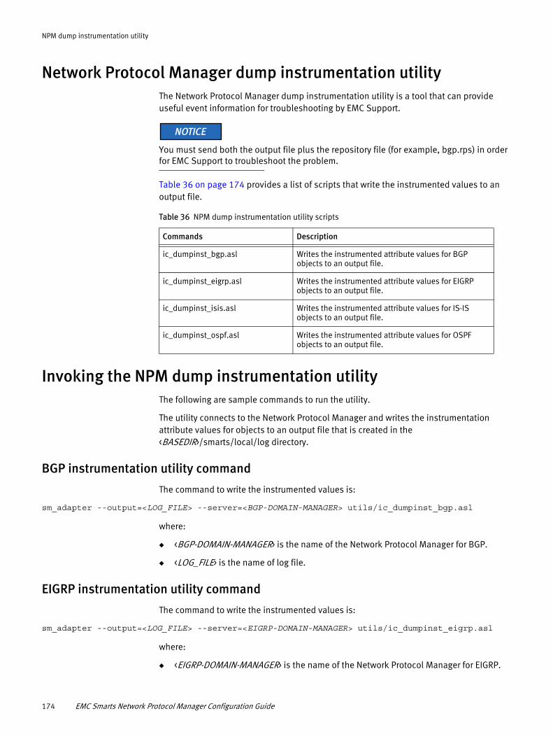
NPM dump instrumentation utility
Network Protocol Manager dump instrumentation utilityThe Network Protocol Manager dump instrumentation utility is a tool that can provide useful event information for troubleshooting by EMC Support.
You must send both the output file plus the repository file (for example, bgp.rps) in order for EMC Support to troubleshoot the problem.
Table 36 on page 174 provides a list of scripts that write the instrumented values to an output file.
Table 36 NPM dump instrumentation utility scripts
Commands Description
Invoking the NPM dump instrumentation utility The following are sample commands to run the utility.
The utility connects to the Network Protocol Manager and writes the instrumentation attribute values for objects to an output file that is created in the <BASEDIR>/smarts/local/log directory.
BGP instrumentation utility command
The command to write the instrumented values is:
sm_adapter --output=<LOG_FILE> --server=<BGP-DOMAIN-MANAGER> utils/ic_dumpinst_bgp.asl
where:
◆ <BGP-DOMAIN-MANAGER> is the name of the Network Protocol Manager for BGP.
◆ <LOG_FILE> is the name of log file.
EIGRP instrumentation utility command
The command to write the instrumented values is:
sm_adapter --output=<LOG_FILE> --server=<EIGRP-DOMAIN-MANAGER> utils/ic_dumpinst_eigrp.asl
where:
◆ <EIGRP-DOMAIN-MANAGER> is the name of the Network Protocol Manager for EIGRP.
ic_dumpinst_bgp.asl Writes the instrumented attribute values for BGP objects to an output file.
ic_dumpinst_eigrp.asl Writes the instrumented attribute values for EIGRP objects to an output file.
ic_dumpinst_isis.asl Writes the instrumented attribute values for IS-IS objects to an output file.
ic_dumpinst_ospf.asl Writes the instrumented attribute values for OSPF objects to an output file.
174 EMC Smarts Network Protocol Manager Configuration Guide
NPM dump instrumentation utility
◆ <LOG_FILE> is the name of log file.
IS-IS instrumentation utility command
The command to write the instrumented values is:
sm_adapter --output=<LOG_FILE> --server=<IS-IS-DOMAIN-MANAGER> utils/ic_dumpinst_isis.asl
where:
◆ <IS-IS-DOMAIN-MANAGER> is the name of the Network Protocol Manager for IS-IS.
◆ <LOG_FILE> is the name of log file.
OSPF instrumentation utility command
The command to write the instrumented values is:
sm_adapter --output=<LOG_FILE> --server=<OSPF-DOMAIN-MANAGER> utils/ic_dumpinst_ospf.asl
where:
◆ <OSPF-DOMAIN-MANAGER> is the name of the Network Protocol Manager for OSPF.
◆ <LOG_FILE> -is the name of log file.
Invoking the NPM dump instrumentation utility 175

NPM dump instrumentation utility
176 EMC Smarts Network Protocol Manager Configuration Guide

INDEX
AAccessProtocol 54Adapter for Alcatel-Lucent 5620 SAM EMS 131, 133, 135
5620 polling groups 127IsDisplayNameCustom 34
Adapter PlatformConfiguration tasks 20Overview 17
Adapters 34, 127, 131, 133, 135Adding or removing matching criteria 118AdminDownFlag parameter 28, 30, 31, 34AllowedAuthentications option 109AnalysisMode
BGP External Setting 129BGP SNMP Setting 128EIGRP CLI Setting 130ISIS CISCO CLI Setting 132OSPF External Setting 135OSPF SNMP Setting 134
Architecture, Network Protocol Manager 13Authentication
Host-based 102Password 102Public-key 102
BBGP External Setting 128
AnalysisMode 129PeerState 129
BGP light discovery 29BGP maps
Enabling 75BGP polling group 126, 127BGP Protocol Endpoints threshold group 137BGP Session Flapping threshold setting 137
FLAP_Clear_Window 138Trap_Count_Threshold 138Trap_Time_Window 138
BGP SNMP Setting 127AnalysisMode 128PollingInterval 128Retries 128Timeout 128
bgp.conf file 23, 25, 27SyslogName 26TrapPort 26, 27
BrokerOverview 18
CChanging matching criteria 118Changing priority of a group 117Changing setting parameters 116
Cisco Devices polling group 126, 131CLI
Discovery 17Polls 17, 124, 170
CLI Access SettingAccessProtocol 54LoginID 54Password 54PrivilegedModePassword 54Timeout 54
CLI commandsshow clns neighbors detail 132, 166show ip eigrp neighbors 130, 166
CLI modulesDASL CLI module 102Perl CLI module 102
Config parameter 27, 30, 31, 33Configuration files
bgp.conf 23, 27eigrp.conf 23, 30isis.conf 23, 31ospf.conf 23, 33trapd.conf 81, 85
Configuration roadmap 18Configuring syslog message forwarding 97Consoles
Polling and Thresholds Console 112Copying a group 119Creating a group 119
DDASL CLI module 102Device
Definition of 12Device Access tab 113Device support
MSFCs 47Physical routers 47RSFCs 47RSMs 47Virtual routers 47
Discoverybgp.conf 27eigrp.conf 30isis.conf 31Light 29ospf.conf 33perl-cli.conf 104, 106Route Reflectors 28Seed file
Creating 88SNMP and CLI 17
Domain ManagerDefinition of 12
EMC Smarts Network Protocol Manager Configuration Guide 177

Index
EEIGRP CLI Setting 130
AnalysisMode 130PollingInterval 130Retries 130Timeout 131
EIGRP EXTERNAL Setting 131eigrpPeerAdminStatus 131PeerState 131
EIGRP mapsEnabling 75
EIGRP polling group 126, 130eigrp.conf file 23, 25, 30eigrpPeerAdminStatus
EIGRP EXTERNAL Setting 131EnableAlertsOnDynamicOSPFLinks 34EnablePeriodicLiteSynchronization 29EnableReconfigureLaunchedLiteSynchronization 29EnableRRDiscovery parameter 28Enabling maps 75
Console Operations 75Global Manager Administration Console 75User Profiles 75
FFLAP_Clear_Window 138FORWARD entries 86, 87
GGlobal Console
Overview 18, 39Overview discussion 38Polling and Thresholds Console 113Polling, Thresholds, and Device Access 38Type of
Domain Manager Administration 38Global Manager Administration 38Topology Browser Console 64
Global Manager 17Configuration tasks 19Enabling maps 75Overview 17
Global Manager Administration Console 58, 61, 62, 91Group
Changing priority 117Copying 119Creating 119Definition of 114Polling 126
BGP 126, 127Cisco Devices 126, 131EIGRP 126, 130Juniper Devices 126, 133OSPF 126, 134
Properties 115Threshold 137
BGP Protocol Endpoints 137
HHost-based authentication 102
Iic_dumpinst_bgp.asl 174ic_dumpinst_eigrp.asl 174ic_dumpinst_isis.asl 174ic_dumpinst_ospf.asl 174Importing
Topology information 18Topology objects 91
InitialAdminStatusOSPF External Setting 135
InitialIfStateOSPF External Setting 135
InitialMulticastIfStateOSPF External Setting 135
InitialNeighborStateOSPF External Setting 136
InitialNonMulticastIfStateOSPF External Setting 136
InitialVirtualNeighborStateOSPF External Setting 136
InitialVirtualStateOSPF External Setting 136
IP Availability ManagerConfiguration tasks 19Overview 16
IP tagging feature 49IsDisplayNameCustom parameter 28, 34ISIS CISCO CLI Setting 132
AnalysisMode 132PollingInterval 132Retries 132Timeout 132
ISIS EXTERNAL Setting 133, 134NeighborState 133
ISIS JUNIPER SNMP Setting 133IS-IS maps
Enabling 75isis.conf file 23, 25, 31
JJuniper Devices polling group 126, 133
LLiteSynchronizationInterval 29LoginID 54
MMatching
Pattern 140Matching criteria
Adding or removing 118Changing 118
178 EMC Smarts Network Protocol Manager Configuration Guide

IndexIndex
NNeighbor Down alarm
Control 34NeighborState
ISIS EXTERNAL Setting 133Network Protocol Manager
Configuration tasks 18Overview 16Polling 170Repository file 25, 26
Network Protocol Manager architecture 13NPM dump instrumentation utility 174
OObject
Definition of 12Tagged IP 48
OperatorWildcard 140
OSPF External Setting 135AnalysisMode 135InitialAdminStatus 135InitialIfState 135InitialMulticastIfState 135InitialNeighborState 136InitialNonMulticastIfState 136InitialVirtualNeighborState 136InitialVirtualState 136
OSPF mapsEnabling 75
OSPF polling group 126, 134OSPF SNMP Setting 134
AnalysisMode 134PollingInterval 134Retries 134Timeout 135
ospf.conf file 23, 25, 33TrapPort 33
PParameter
Override 25Password 54Password authentication 102PasswordAuthentication option 109Pattern 140Pattern matching 140PeerState
BGP External Setting 129EIGRP EXTERNAL Setting 131
Perl CLI module 102perl-cli.conf 104, 106Polling
CLI 124, 170Groups 127, 130, 131, 134SNMP 124, 170SNMP and CLI 17
Polling and Thresholds Console 112Device Access tab 113
Layout 113Polling tab 112Tagging tab 113Thresholds tab 113Toolbar buttons 113
Polling tab 112PollingInterval
BGP SNMP Setting 128EIGRP CLI Setting 130ISIS CISCO CLI Setting 132OSPF SNMP Setting 134
PriorityChanging 117
PrivilegedModePassword 54PrivLevel parameter 30, 32ProhibitPrivLevelCLILogon parameter 30, 31Public-key authentication 102
RRemoving or adding matching criteria 118Repository
Location 25, 26Restoring default values of a setting 117Retries
BGP SNMP Setting 128EIGRP CLI Setting 130ISIS CISCO CLI Setting 132OSPF SNMP Setting 134
SSecurity 36
clientConnect.conf 36Secure communications 36serverConnect.conf 36SSH security 99
Seed file 88Creating 88
Service Assurance ManagerSee Global Manager
SettingChanging parameters 116Definition of 114Restoring default values 117
show clns neighbors detail 132, 166show ip eigrp neighbors 130, 166sm_service install command 92sm_service start command 93SNMP
BGP trapsList of 146
Cisco configuration trapsList of 147, 154
Discovery 17Instrumentation BGP4 MIB objects
List of 144Instrumentation IS-IS MIB objects
List of 155, 156, 157Instrumentation OSPF MIB objects
List of 147, 148
EMC Smarts Network Protocol Manager Configuration Guide 179

Index
OSPF trapsList of 153
Polling 170Polls 17, 124, 170Trap
bgpEstablished 137Trap messages 79TrapPort 26, 27, 33
SNMP Trap Adapter 79Editing the trapd.conf File 85
SNMP trap and syslog processing 147, 155SSH options
AllowedAuthentications 109PasswordAuthentication 109
Starting syslog message forwarding 97Syslog
Message format 160Sample messages 160Syslog messages 97SyslogName 26
Syslog adapter, built-in 97Syslog message forwarding
Configuring 97Starting 97
SyslogName 26SyslogName parameter 27, 33System
Definition of 12
TTagged IP objects 48Tagging tab 113Threshold
Groups 137Thresholds tab 113Timeout 54
BGP SNMP Setting 128EIGRP CLI Setting 131ISIS CISCO CLI Setting 132OSPF SNMP Setting 135
TopologyFile location 25, 26
Topology Browser 64Topology Browser Console 40Topology Importer 18TraceSyslog parameter 27, 33TraceTraps parameter 27, 33Trap
Authentication 80Decryption 80PORT parameter 81Processing 79SNMP messages 79SNMP Trap Adapter 79Translation of incoming 80Versions 80
Trap exploder 79Creating a service for 92Starting a service for 93
Trap receiver 81
Trap receiver, built-in 79Trap_Count_Threshold 138Trap_Time_Window 138trapd.conf file 85
FORWARD entries 86, 87TrapPort 26, 27, 33Traps required for IP Availability Manager 87Traps required for Network Protocol Manager for BGP 86Traps required for Network Protocol Manager for OSPF 87Traps selected for the trap receiver 88Troubleshooting
NPM dump instrumentation 174
UUser Profiles
Configure 75
WWildcard 140
Chart of operators 140
180 EMC Smarts Network Protocol Manager Configuration Guide