Embed Size (px)
Citation preview
EMC Models

2 19 Apr 2023
1. Models, what for ?
2. IC Models for EMC
3. Core Model
4. Package model
5. Test-bench models
6. Emission measurements/simulations
7. Immunity measurements/simulations
8. Conclusion
Summary
3 19 Apr 2023
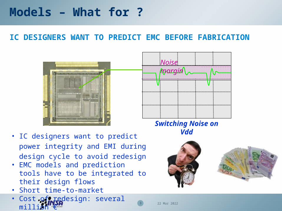
IC DESIGNERS WANT TO PREDICT EMC BEFORE FABRICATION
Models – What for ?
Noise margin
Switching Noise on Vdd
• IC designers want to predict power
integrity and EMI during design cycle to
avoid redesign • EMC models and prediction tools have to
be integrated to their design flows• Short time-to-market• Cost of redesign: several million €
4 19 Apr 2023
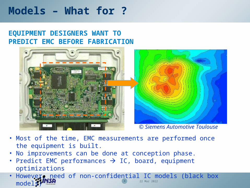
© Siemens Automotive Toulouse
• Most of the time, EMC measurements are performed once the equipment is built.
• No improvements can be done at conception phase.• Predict EMC performances IC, board, equipment optimizations• However, need of non-confidential IC models (black box models)
Models – What for ?
EQUIPMENT DESIGNERS WANT TO PREDICT EMC BEFORE FABRICATION
5 19 Apr 2023
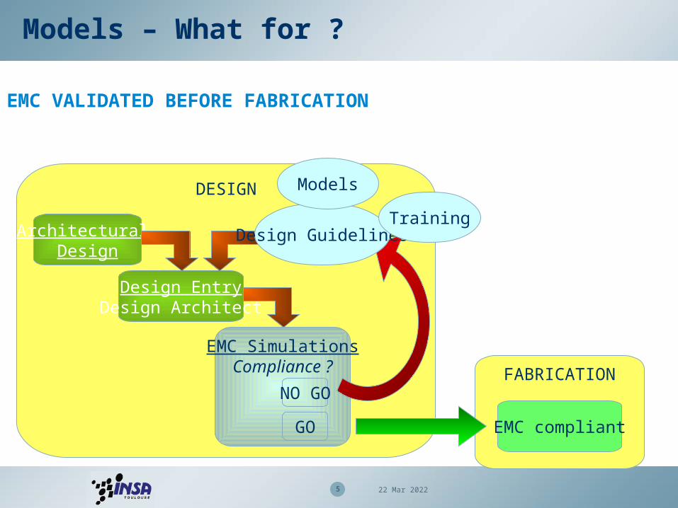
DESIGN
Architectural Design
Design EntryDesign Architect
FABRICATION
EMC compliant
EMC SimulationsCompliance ?
GO
NO GO
EMC VALIDATED BEFORE FABRICATION
Design Guidelines
Models
Training
Models – What for ?

6 19 Apr 2023
Complexity
Level
Equipment
Board
Component
Physicalspice
V, Z
106 R,L,C,ILEECS
ICEM
Dipoles
102 R,L,C,I
101 R,L,C,I
101 dipoles
100 V(f), 100 Z(f)
x-highhighlow medium
Expo PowerSI
104 R,L,C,I
EMC MODELS DEPENDS ON THE TARGETED COMPLEXITY, THE LEVEL OF CONFIDENTIALITY OF INFORMATION.
Confidentiality
IC models for EMC

7 19 Apr 2023
IC models for EMC
Core – I/O Model
Package ModelTest bench Model Test board Model
EMC Model for the circuit
Electrical Simulation
Simulated Emission spectrum
GENERAL FLOW TO BUILD AN EMC MODEL AND PREDICT EMC PERFORMANCES
IEC 62433
8 19 Apr 2023
IC models for EMC
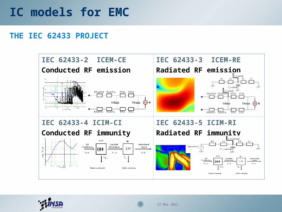
THE IEC 62433 PROJECT
IEC 62433-2 ICEM-CE
Conducted RF emission
IEC 62433-3 ICEM-RE
Radiated RF emission
IEC 62433-4 ICIM-CI
Conducted RF immunity
IEC 62433-5 ICIM-RI
Radiated RF immunity
9 19 Apr 2023
IC models for EMC
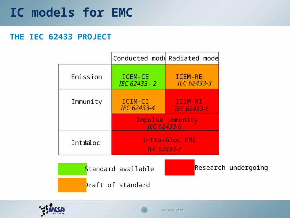
THE IEC 62433 PROJECT
Conducted mode Radiated mode
Emission
Immunity
Intra-bloc
ICEM-CE
IEC 62433 - 2
ICEM-RE IEC 62433-3
ICIM-CI
IEC 62433-4
ICIM-RI
IEC 62433-5
Impulse immunity IEC 62433-6
Intra-bloc EMC IEC 62433-7
Standard available
Draft of standard
Research undergoing

10 19 Apr 2023
IC models for EMC
IEC 62433-2 – “ICEM Conducted Mode”
IAPDN
(including package)
IA
IA
PDNof PCB
IC model
IA = Internal Activity
PDN = Power Distribution Network
IT = Internal Terminal
ET = External Terminal
PDN(including package)
PDN(including package)
IBCIBC
IBCIBC
IT
IT
IT
IT
IT IT
IT IT
IT IT
IT IT
IT IT
IT IT
IT IT
IT IT
ET
ET
ET
ET
ET ET
ET ET
ET ET
ET ET
ICEM-CE Block A
ICEM-CE Block B
ICEM-CE Block C
Example : Digital core
Example : Analog core
Example : I/O buffers
Package
IA
PDN
IT

11 19 Apr 2023
100 mA
3 A
32 bit processor500 MHz
62.5 ns 2 ns
16 bit processor
16 MHz
I
time
Core model
INTERNAL ACTIVITY (IA) - CURRENT SOURCE EXTRACTION
time
I
Extraction of internal current waveform
1st order assumption : model core activity by triangular waveform current source
IAPDN
(including package)
IA
IA
PDNof PCB
IC model
IA = Internal Activity
PDN = Power Distribution Network
IT = Internal Terminal
ET = External Terminal
PDN(including package)
PDN(including package)
IBCIBC
IBCIBC
IT
IT
IT
IT
IT IT
IT IT
IT IT
IT IT
IT IT
IT IT
IT IT
IT IT
ET
ET
ET
ET
ET ET
ET ET
ET ET
ET ET
ICEM-CE Block A
ICEM-CE Block B
ICEM-CE Block C
Example : Digital core
Example : Analog core
Example : I/O buffers

12 19 Apr 2023
Physical Transistor level (Spice)
Huge simulation
Limited to analog blocks
Interpolated Transistor level
Difficult adaptation to usual tools
Limited to 1 M devices
Simple, not limited
Fast & accurate
Gate level Activity (Verilog)
time (ns)0
20040060080010001200
0 20 40 60 80 100 120 140
Activity
Activity estimation from data sheet
Very simple, not limited
Immediate, not accurate
Core model
INTERNAL ACTIVITY (IA) – FROM PHYSICAL TO FIRST-ORDER ESTIMATION
Equivalent Current
generatorExtraction
In this course
IAPDN
(including package)
IA
IA
PDNof PCB
IC model
IA = Internal Activity
PDN = Power Distribution Network
IT = Internal Terminal
ET = External Terminal
PDN(including package)
PDN(including package)
IBCIBC
IBCIBC
IT
IT
IT
IT
IT IT
IT IT
IT IT
IT IT
IT IT
IT IT
IT IT
IT IT
ET
ET
ET
ET
ET ET
ET ET
ET ET
ET ET
ICEM-CE Block A
ICEM-CE Block B
ICEM-CE Block C
Example : Digital core
Example : Analog core
Example : I/O buffers
13 19 Apr 2023
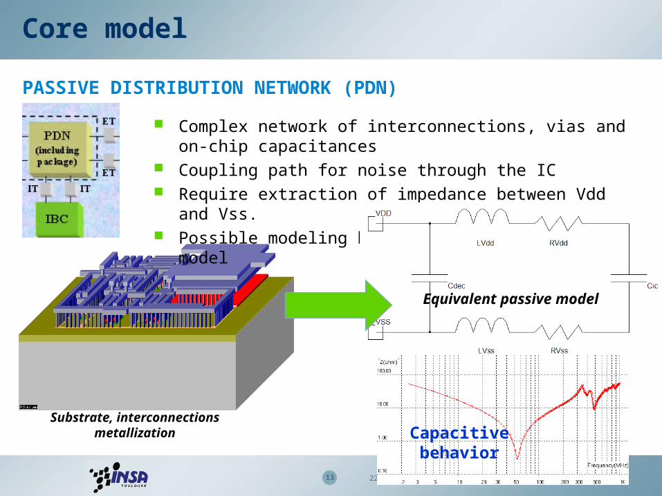
Core model
PASSIVE DISTRIBUTION NETWORK (PDN)
Complex network of interconnections, vias and on-chip capacitances
Coupling path for noise through the IC Require extraction of impedance between Vdd and Vss. Possible modeling by an equivalent passive model
Equivalent passive model
Substrate, interconnections metallization Capacitive
behavior
14 19 Apr 2023
Package model IC model
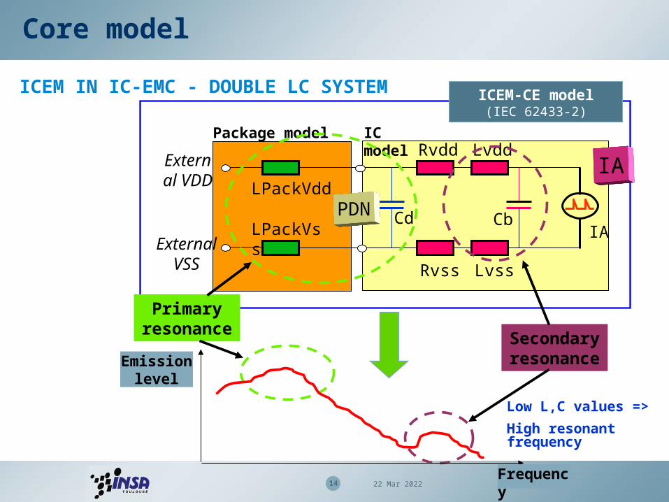
Core model
ICEM IN IC-EMC - DOUBLE LC SYSTEM
IA
Rvdd
Cd
Lvdd
Rvss Lvss
Cb
LPackVdd
LPackVss
External VDD
External VSS
Secondary resonance
Primary resonance
Frequency
Emission level
Low L,C values =>
High resonant frequency
ICEM-CE model(IEC 62433-2)
PDN
IA
15 19 Apr 2023
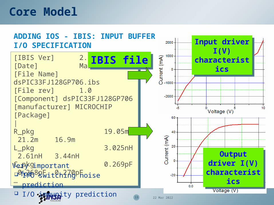
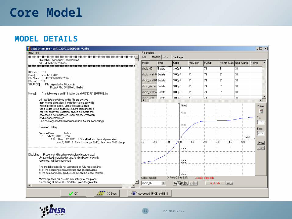
[IBIS Ver] 2.1[Date] March 17,2011[File Name] dsPIC33FJ128GP706.ibs[File rev] 1.0[Component] dsPIC33FJ128GP706[manufacturer] MICROCHIP[Package]|R_pkg 19.05m 21.2m 16.9mL_pkg 3.025nH 2.61nH 3.44nH C_pkg 0.269pF 0.268pF 0.270pF…
[IBIS Ver] 2.1[Date] March 17,2011[File Name] dsPIC33FJ128GP706.ibs[File rev] 1.0[Component] dsPIC33FJ128GP706[manufacturer] MICROCHIP[Package]|R_pkg 19.05m 21.2m 16.9mL_pkg 3.025nH 2.61nH 3.44nH C_pkg 0.269pF 0.268pF 0.270pF…
Core Model
ADDING IOS - IBIS: INPUT BUFFER I/O SPECIFICATION
IBIS fileIBIS file
I/O switching noise prediction I/O immunity prediction
Very important for :
Input driver I(V) characteristics
Input driver I(V) characteristics
Output driver I(V) characteristics
Output driver I(V) characteristics
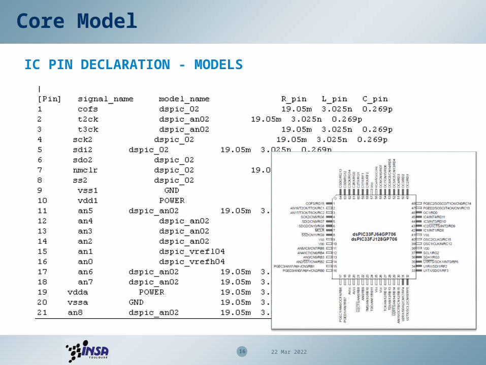
Core Model
16 19 Apr 2023
IC PIN DECLARATION - MODELS
17 19 Apr 2023
Core Model
MODEL DETAILS

Core Model
18 19 Apr 2023
ADDING IOS – SIGNAL TRANSPORT
19 19 Apr 2023
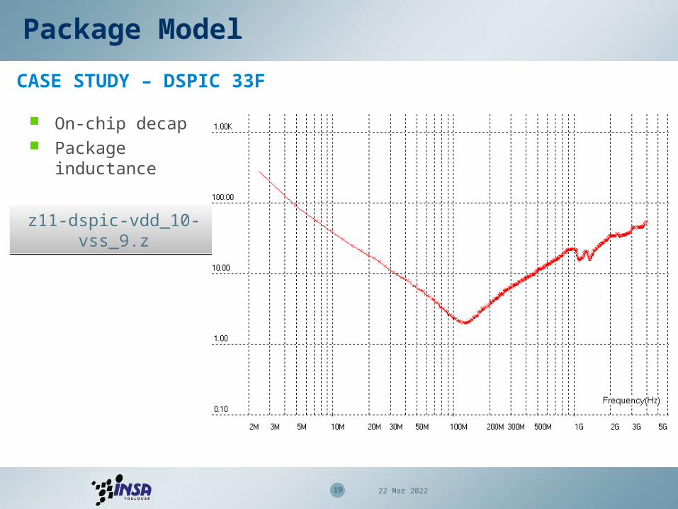
Package Model
CASE STUDY – DSPIC 33F
z11-dspic-vdd_10-vss_9.zz11-dspic-vdd_10-vss_9.z
On-chip decap Package
inductance
20 19 Apr 2023
1 To receiver
DUT
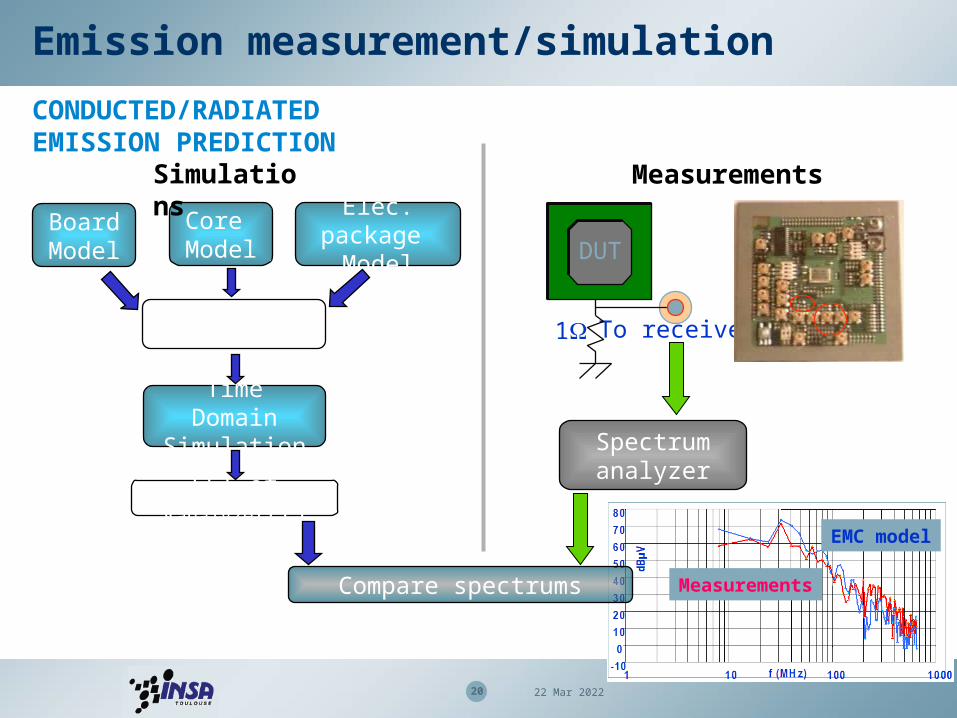
Emission measurement/simulation
CONDUCTED/RADIATED EMISSION PREDICTION
Time Domain Simulation
FFT of Vanalyzer(t)
EMC model
Measurements
Core Model
Elec. package Model
BoardModel
IC Model
Spectrum analyzer
Compare spectrums
Simulations Measurements

21 19 Apr 2023
ICEM-CE CASE STUDY – DSPIC 33F
Emission measurement/simulation
Core only

22 19 Apr 2023
ICEM-CE CASE STUDY – DSPIC 33F
Emission measurement/simulation
Core + 16 ADDR 20dB more noise
than core

23 19 Apr 2023
Emission measurement/simulation
ICEM-RE – CURRENT DIPOLE THEORY
chip
Vdd
Vss
I(vdd)
I(vss)
P
H1
H2
i
iHPH
r P
H
IL
Package is the main contributor of the radiated emission of an IC
Magnetic field emission is generated by the flowing of parasitic current through package pins
Magnetic near field scan of a 16 bit microcontroller

24 19 Apr 2023
Scan Simulations
Core Model
Elec. package Model
Analog Time Domain Simulation
Fourier Transform of I(t)
Compare scans
Scan Measurements
Spectrum analyser
H[x,y] at given f, given z
Positionning [x,y]
Emission measurement/simulation
Geometrical package model
VssX1 VssA
VssX2VssR2
Vss2
Vdd2
Vss1
Vdd1
VssR1 VddR1
H[x,y,z] of I(f)
ICEM-RE – SIMULATION/MEASUREMENT

25 19 Apr 2023
Emission measurement/simulation
ICEM-RE – RADIATING DIPOLES
IA
PDN
IT
IT

26 19 Apr 2023
Passive elements
IB Active elements
Residual disturbances
Behavioural output
PDN RF
Disturbances
Vin, Iin
Vr, Ir
Vo, Io IEC 62433-4
IC models for EMC
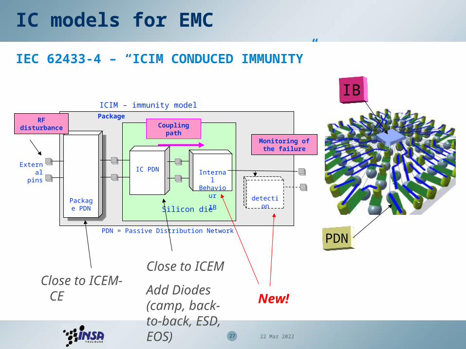
IEC 62433-4 – “ICIM CONDUCED IMMUNITY”
• The package and die impedance act as a coupling path for RF interference (Vin, Iin) to the active blocks,
• Filtering effect and/or distortion through the PDN and produce (Vr,Ir).
• The IB block describes how the circuit reacts to internal perturbations, and can be represented as (Vout,Iout) for monitoring the failure
27 19 Apr 2023
IC models for EMC
IEC 62433-4 – “ICIM CONDUCED IMMUNITY”
Package
IB
PDN
Package PDN
Package PDN Silicon die
IC PDN Internal Behavio
ur
IB
External pins
ICIM – immunity modelPackage
Monitoring of the failure
PDN = Passive Distribution Network
detection
RF disturbance Coupling
path
Close to ICEM-CEClose to ICEM
Add Diodes (camp, back-to-back, ESD, EOS)
New!
28 19 Apr 2023
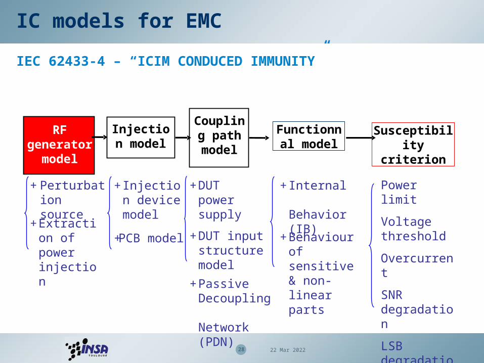
Functionnal model
Coupling path
model
RF generator
model
Susceptibility criterion
+ Internal Behavior (IB)
+Behaviour of sensitive & non-linear parts
+DUT power supply
+DUT input structure model
+Passive Decoupling Network (PDN)
+ Perturbation source
+Extraction of power injection
Injection model
+Injection device model
+PCB model
Power limit
Voltage threshold
Overcurrent
SNR degradation
LSB degradation….
IC models for EMC
IEC 62433-4 – “ICIM CONDUCED IMMUNITY”
29 19 Apr 2023
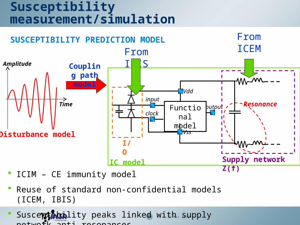
Susceptibility measurement/simulation
SUSCEPTIBILITY PREDICTION MODEL
Functional model
outputinput
clock
Vdd
Vss
Resonance
I/O
Supply network Z(f)
Time
Amplitude
Disturbance model
IC model
From ICEMFrom
IBISCoupling path model
ICIM – CE immunity model
Reuse of standard non-confidential models (ICEM, IBIS)
Susceptibility peaks linked with supply network anti-resonances
30 19 Apr 2023
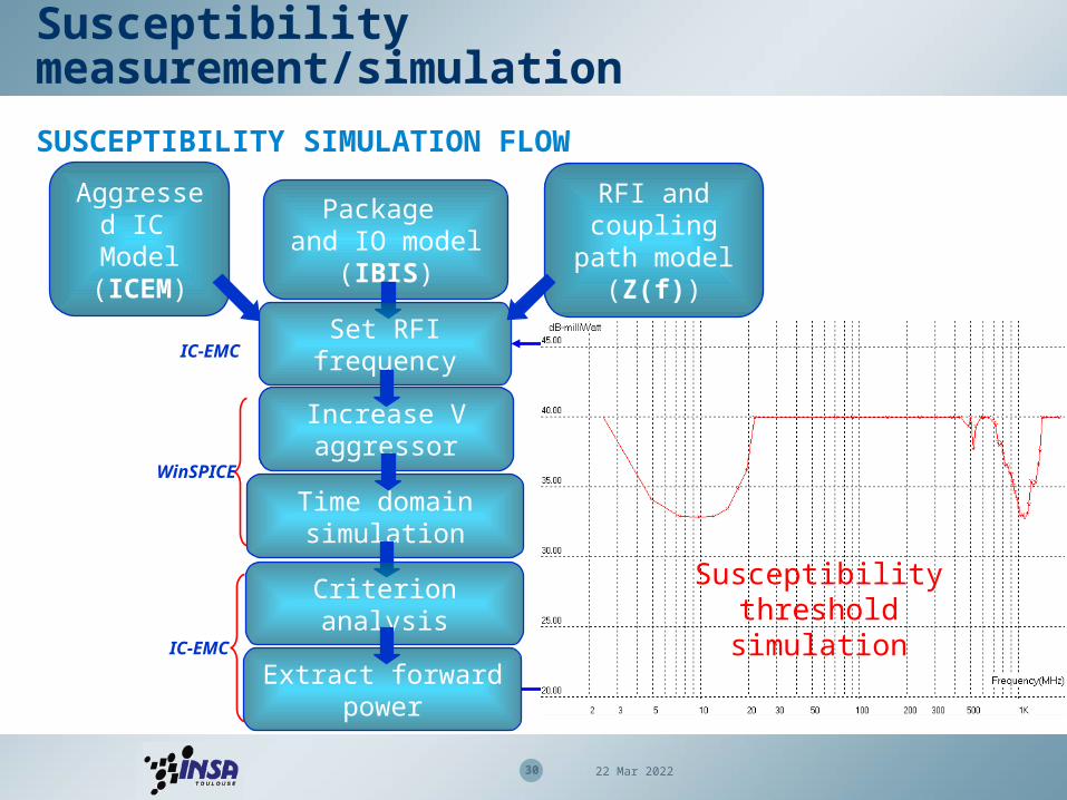
Susceptibility measurement/simulation
SUSCEPTIBILITY SIMULATION FLOW
Aggressed IC Model (ICEM)
Package and IO model (IBIS)
RFI and coupling path model (Z(f))
Set RFI frequencyIC-EMC
Increase V aggressor
Time domain simulation
WinSPICE
Criterion analysis
Extract forward power
IC-EMC
Increase RFI frequency
Susceptibility threshold simulation

31 19 Apr 2023
Test bench model
DPI capacitance
C=1nF
L=0.5nH
R=15mΩ
Electrical model extracted by S parameter measurements and electromagnetic simulations
Test bench models should be generic
Limited frequency range due to influence of parasitic elements, apparition of high order propagation mode
TEST BENCH MODEL
TEM CellDPI injection
DUT
TEM
K=1%C=20fF
Near-field scanDUT
K=6%
L=4nHR=1Ω

32 19 Apr 2023
Susceptibility case study
DPI ON A 330 OHM LOAD
Immunity > Dpi330ohm
33 19 Apr 2023
• EMC models can help earn/save money
• Macro-models of ICs include core, I/O and package modeling
• The core model is based on current evaluation and on-chip
capacitance
• The package model is based on RLC
• Good prediction of emission and susceptibility up to 2 GHz
• Soon, requirements up to 3-10 GHz
Conclusion