Embed Size (px)
Citation preview

EMC CorporationCorporate Headquarters:
Hopkinton, MA 01748-9103
1-508-435-1000www.EMC.com
EMC® GDDR for SRDF®/S with AutoSwap™Version 2.2
Product GuideP/N 300-006-599
REV A03

EMC GDDR for SRDF/S with AutoSwap Product Guide 2
Copyright © 2007-2008 EMC Corporation. All rights reserved.
Published May, 2008
EMC believes the information in this publication is accurate as of its publication date. The information is subject to change without notice.
THE INFORMATION IN THIS PUBLICATION IS PROVIDED “AS IS.” EMC CORPORATION MAKES NO REPRESENTATIONS OR WARRANTIES OF ANY KIND WITH RESPECT TO THE INFORMATION IN THIS PUBLICATION, AND SPECIFICALLY DISCLAIMS IMPLIED WARRANTIES OF MERCHANTABILITY OR FITNESS FOR A PARTICULAR PURPOSE.
Use, copying, and distribution of any EMC software described in this publication requires an applicable software license.
For the most up-to-date listing of EMC product names, see EMC Corporation Trademarks on EMC.com.
All other trademarks used herein are the property of their respective owners.
For the most up-to-date regulatory document for your product line, go to the Technical Documentation and Advisories section on EMC Powerlink.

Contents
Preface
Chapter 1 Installing EMC GDDR Introduction............................................................................................................. 16 Pre-installation tasks .............................................................................................. 17
Mainframe environment requirements ......................................................... 17Minimum software requirements .................................................................. 17Minimum hardware requirements ................................................................ 18
Installation procedure ............................................................................................ 19Gather EMC GDDR installation information ............................................... 19Installing EMC GDDR ..................................................................................... 20Run the installation jobs .................................................................................. 25
Post-installation tasks............................................................................................. 26
Chapter 2 Integrating EMC GDDR Overview.................................................................................................................. 28 Update system parameter files ............................................................................. 29 Perform ConGroup Started Task automated startup ........................................ 31 Specify EMC GDDR security ................................................................................ 33
EMC GDDR RACF functional groups........................................................... 33Summary of RACF permissions ..................................................................... 33RACF authorization for OMVS ...................................................................... 34
Install EMC GDDR started procedures ............................................................... 35Install EMC z/OS Console Monitor started procedures ............................ 35
Customize CA-OPS/MVS for EMC GDDR ........................................................ 36Include EMC GDDR libraries in OPSVIEW REXX exec ............................. 36Make EMC GDDR AOF rules available to CA-OPS/MVS ........................ 36Change CA-OPS/MVS access rules............................................................... 36Customize EMC GDDR user exit 7 (optional).............................................. 37Update CA-OPS/MVS started procedure OPSOSF .................................... 37Customize the REXX exec defining the specifications for the CA-OPS/MVS copy on each C-System......................................................... 37Update the Unix system service directory.................................................... 37Define the EMC GDDR monitoring started tasks to CA-OPS/MVS SSM 38Merge CA-OPS/MVS user applications ....................................................... 39Update CA-OPS/MVS CCI parameters........................................................ 39
Modify CA-OPS/MVS to use the GDDRMSG table ......................................... 40 Configure EMC GDDR .......................................................................................... 41
EMC GDDR for SRDF/S with AutoSwap Product Guide 3

Contents
Allocate the parameter backup dataset ......................................................... 41Customize member GDDRPROC................................................................... 41Prepare and load EMC GDDR parameters ................................................... 42Specify EMC GDDR job defaults .................................................................... 47Configure the EMC GDDR HMC interface................................................... 47Configuring multiple EMC GDDR parameter members (optional).......... 49Modifying EMC GDDR user exits (optional)................................................ 50
Chapter 3 Using EMC GDDR Online Facilities Introduction ............................................................................................................. 52 EMC GDDR administrator facilities..................................................................... 53
Option A — Automation: Toggle GDDR Automation On/Off ................. 54Option C — Config: View GDDR configuration.......................................... 55Option H — HMC: Manage HMC.................................................................. 56Option J — JobVals: View or change default job values ............................. 58Option M — MsgOut: Specify GDDR message output options................. 59Option P — Parms: Update GDDR parameters ........................................... 60Option Q — Queue: Manage GDDR internal command queue ................ 73Option R — ManagePrms: Manage GDDR parameters.............................. 74Option S — Systems: Configure GDDR production systems..................... 80
EMC GDDR ISPF profiles ...................................................................................... 81 Using OPSVIEW facilities for EMC GDDR administration.............................. 82
Ensuring MSF connections between C-Systems........................................... 82
Chapter 4 EMC GDDR Parameters Introduction ............................................................................................................. 84
User environment parameters ........................................................................ 84Performance and tuning parameters ............................................................. 84
Parameter statement processing ........................................................................... 85Components....................................................................................................... 85References and specifications.......................................................................... 85Associations ....................................................................................................... 85Validation........................................................................................................... 86
Loading the parameters ......................................................................................... 87Validating the environment ............................................................................ 87Backing up existing global variables.............................................................. 87Loading global variables.................................................................................. 87
Parameter descriptions........................................................................................... 88 User environment parameters............................................................................... 89
Autoswap.Group.Primary ............................................................................... 89Autoswap.Group.Secondary........................................................................... 90BCV.siteid.swap-group .................................................................................... 91CGRP................................................................................................................... 93CONCAT.JCLLIB.seq ....................................................................................... 94CONCAT.SKELS.seq ........................................................................................ 95ConGroups_CntlDsn.system-name................................................................ 96ConGroups_STC_Name.system-name .......................................................... 97CONT.system-name ......................................................................................... 98siteid.C.System.Systemid................................................................................. 99GDDR.Call_Override ..................................................................................... 100GDDR.CONFIG............................................................................................... 101GDDRVAR_BACKUP .................................................................................... 102GNS.siteid.loc.jtype ........................................................................................ 103
EMC GDDR for SRDF/S with AutoSwap Product Guide4

Contents
HMC.siteid ...................................................................................................... 104HostComponent_CntlDsn............................................................................. 105IPL.system-name.siteid.................................................................................. 106IPLBCVS.system-name.siteid ....................................................................... 108J0_GK.siteid ..................................................................................................... 109siteid.LPAR.system-name ............................................................................. 110MSFID.system-name ...................................................................................... 111ResourcePak_STC_Name.c-system-name................................................... 112SITE.system-name .......................................................................................... 113SRDFS.Devices.siteid ..................................................................................... 114sPLX.system-name.type.aorp.siteid............................................................. 115
Performance and tuning parameters ................................................................. 116ECGCLEAN.MSGLEVEL.............................................................................. 116ECGCLEAN.Task.Number ........................................................................... 117Event.Monitor.Interval .................................................................................. 118Heartbeat.Monitor.Interval ........................................................................... 119HMC_Timeout.siteid ..................................................................................... 120Missing.Heartbeat.Interval............................................................................ 121Missing.Heartbeat.Threshold ....................................................................... 122SMF_Record_Type ......................................................................................... 123WTOR_Wait_Interval .................................................................................... 124
Chapter 5 EMC GDDR Maintenance Procedures Setting up a new EMC GDDR C-System........................................................... 126 Renaming an existing EMC GDDR C-System.................................................. 128 Adding a new production system or sysplex to EMC GDDR ....................... 129 Changing the AutoSwap group name............................................................... 131 Adding new RDF groups to EMC GDDR ......................................................... 132 Adding new devices to EMC GDDR ................................................................. 134 Removing an RDF group from EMC GDDR control....................................... 135 Removing devices from EMC GDDR control................................................... 136 Removing a system or a sysplex from EMC GDDR ........................................ 137
EMC GDDR AOF rule set.............................................................................. 137Update CA-OPS/MVS MSF parameters..................................................... 137Update CA-OPS/MVS CCI parameters...................................................... 137
Special cases........................................................................................................... 138Non-LOGR couple datasets ......................................................................... 138
Appendix A EMC GDDR User ExitsUser exit programming considerations ............................................................. 140
Built-in routines available to exits................................................................ 140Exit specifications ................................................................................................. 141
GDDRUX01 ..................................................................................................... 141GDDRUX02 ..................................................................................................... 141GDDRUX03 ..................................................................................................... 142GDDRUX04 ..................................................................................................... 142GDDRUX05 ..................................................................................................... 142GDDRUX06 ..................................................................................................... 143GDDRUX07 ..................................................................................................... 144
EMC GDDR for SRDF/S with AutoSwap Product Guide 5

Contents
Appendix B Parameter Validation RulesSyntax rules ............................................................................................................ 146Parameter statements providing component specifications ........................... 147Consistency rules ................................................................................................... 148Completeness rules ............................................................................................... 149
Appendix C EMC GDDR Broadcast and Listener Utility Introduction ........................................................................................................... 152 Production system z/OS console monitor — GDDRPBAL ........................... 153 C-System Listener — GDDRCBAL..................................................................... 154 BAL command procesor — BALC...................................................................... 155
BAL CSC ports................................................................................................. 156CSC RTokens ................................................................................................... 156
Index
EMC GDDR for SRDF/S with AutoSwap Product Guide6

Title Page
Figures
1 EMC JCL Customization Utility ......................................................................................... 232 EMC JCL Customization Utility completed panel ........................................................... 253 EMC GDDR Administrator Primary Options Menu ...................................................... 424 Specify GDDR ISPF Skeleton Dataset panel .................................................................... 435 Specify GDDR Procedure Library panel ............................................................................ 436 Specify GDDR Parameter Dataset panel .......................................................................... 447 Load GDDR Parameters panel ............................................................................................ 448 Parameter Member Edit Session panel .............................................................................. 459 Confirm GDDR Parameter Load panel .............................................................................. 4610 CA-OPS/MVS OPSVIEW Primary Options panel ........................................................... 5211 CA-OPS/MVS User Applications panel ............................................................................ 5212 GDDR Administrator Primary Options panel .................................................................. 5313 View GDDR Configuration panel ....................................................................................... 5514 HMC Management Options panel ..................................................................................... 5615 HMC Discovery Results panel ............................................................................................ 5716 Specify HMC Community Names panel ........................................................................... 5717 View or Change Default Job Values panel ........................................................................ 5818 Specify GDDR Message Output panel ............................................................................... 5919 Select the C-System(s) where parameter changes are to be made ................................. 6020 View/Update GDDR Parameter Values panel ................................................................. 6021 View or Change GDDR Tuning Parameters panel (screen 1 of 2) ................................. 6122 View or Change GDDR Tuning Parameters panel (screen 2 of 2) ................................. 6123 View or Change Device Parameters panel (screen 1 of 2) ............................................... 6224 View or Change Device Parameters panel (screen 2 of 2) ............................................... 6225 View or Change Allocation Values panel (screen 1 of 2) ................................................ 6326 View or Change Allocation Values panel (screen 2 of 2) ................................................ 6327 View or Change Dataset Parameters panel (screen 1 of 3) .............................................. 6428 View or Change Dataset Parameters panel (screen 2 of 3) .............................................. 6429 View or Change Dataset Parameters panel (screen 3 of 3) .............................................. 6530 View or Change HMC Parameters panel (screen 1 of 3) ................................................. 6631 View or Change HMC Parameters panel (screen 2 of 3) ................................................. 6632 View or Change HMC Parameters panel (screen 3 of 3) ................................................. 6733 View or Change GDDR GNS Parameters panel ............................................................... 6734 Specify Default Call Override panel (screen 1 of 2) ......................................................... 6835 Specify Default Call Override panel (screen 2 of 2) ......................................................... 6836 View GDDR User Options panel ........................................................................................ 6937 View/Update GDDR Component Lists panel .................................................................. 7038 View GDDR State Values panel (screen 1 of 2) ................................................................. 7239 View GDDR State Values panel (screen 2 of 2) ................................................................. 7240 Manage GDDR Internal Command Queue panel ............................................................ 73
EMC GDDR for SRDF/S with AutoSwap Product Guide 7

Figures
41 Parameter Management Options panel .............................................................................. 7442 Create GDDR Parameter Backup panel ............................................................................. 7443 Restore GDDR Parameters from Backup panel ................................................................ 7644 Specify GDDR Parameter Dataset panel ............................................................................ 7745 Load GDDR Parameters panel ............................................................................................ 7746 Load GDDR Parameters Help panel ................................................................................... 7847 Confirm GDDR Parameter Load panel .............................................................................. 7948 View/Update Configured Production Systems panel ..................................................... 8049 Configure New GDDR Production System panel ............................................................ 80
EMC GDDR for SRDF/S with AutoSwap Product Guide8

Title Page
Tables
1 Mainframe environment requirements .............................................................................. 172 Minimum hardware requirements ..................................................................................... 183 RIMLIB library contents ....................................................................................................... 224 RACF functional groups ...................................................................................................... 335 RACF permissions ................................................................................................................ 336 Parameter statements providing component specifications ......................................... 147
EMC GDDR for SRDF/S with AutoSwap Product Guide 9

Tables
EMC GDDR for SRDF/S with AutoSwap Product Guide10

Preface
As part of an effort to improve and enhance the performance and capabilities of its product lines, EMC periodically releases revisions of its hardware and software. Therefore, some functions described in this document may not be supported by all versions of the software or hardware currently in use. For the most up-to-date information on product features, refer to your product release notes.
If a product does not function properly or does not function as described in this document, please contact your EMC representative.
Note: This document was accurate as of the time of publication. However, as information is added, new versions of this document may be released to the EMC Powerlink website. Check the Powerlink website to ensure that you are using the latest version of this document.
Audience This document is part of the EMC Geographically Dispersed Disaster Restart (EMC GDDR) documentation set, and is intended for use by EMC GDDR systems administrators.
This document describes the basic concepts of EMC GDDR, how to install it, and how to implement its major features and facilities.
Readers of this document are expected to be familiar with the following topics:
◆ IBM z/OS operating environments
◆ IBM parallel sysplex
◆ Unicenter CA-OPS/MVS
◆ EMC software products: SRDF, ResourcePak Base, Consistency Group, and AutoSwap
Relateddocumentation
Related documents include:
◆ EMC GDDR for SRDF/S with AutoSwap Concepts and Facilities Guide
◆ EMC GDDR for SRDF/S with AutoSwap Operations Guide
◆ EMC GDDR Message and Code Guide
◆ EMC GDDR Release Notes
◆ EMC ResourcePak Base for z/OS Product Guide
◆ EMC Symmetrix SRDF Host Component for z/OS Product Guide
◆ EMC Symmetrix Remote Data Facility Product Guide
◆ EMC AutoSwap Product Guide
EMC GDDR for SRDF/S with AutoSwap Product Guide 11

Preface
◆ EMC Consistency Group for z/OS Product Guide
◆ EMC TimeFinder/Mirror for z/OS Product Guide
◆ EMC TimeFinder/Clone Mainframe SNAP Facility Product Guide
◆ EMC REXX Interface Programmer’s Reference Guide
◆ EMC SRDF/Star for z/OS User Guide
◆ Unicenter CA-OPS/MVS for EMC Geographically Dispersed Disaster Restart Documentation CD
Conventions used inthis document
EMC uses the following conventions for special notices.
Note: A note presents information that is important, but not hazard-related.
CAUTION!A caution contains information essential to avoid data loss or damage to the system or equipment. The caution may apply to hardware or software.
IMPORTANT!An important notice contains information essential to operation of the software. The important notice applies only to software.
EMC GDDR — This document uses the acronym EMC GDDR in place of full product name, EMC Geographically Dispersed Disaster Restart.
Typographical conventionsEMC uses the following type style conventions in this document:
Normal Used in running (nonprocedural) text for:• Names of interface elements (such as names of windows, dialog boxes,
buttons, fields, and menus)• Names of resources, attributes, pools, Boolean expressions, buttons,
DQL statements, keywords, clauses, environment variables, filenames, functions, utilities
• URLs, pathnames, filenames, directory names, computer names, links, groups, service keys, file systems, notifications
Bold: Used in running (nonprocedural) text for:• Names of commands, daemons, options, programs, processes,
services, applications, utilities, kernels, notifications, system calls, man pages
Used in procedures for:• Names of interface elements (such as names of windows, dialog boxes,
buttons, fields, and menus)• What user specifically selects, clicks, presses, or types
Italic: Used in all text (including procedures) for:• Full titles of publications referenced in text• Emphasis (for example a new term)• Variables
Courier: Used for:• System output, such as an error message or script • URLs, complete paths, filenames, prompts, and syntax when shown
outside of running text
Courier bold: Used for:• Specific user input (such as commands)
EMC GDDR for SRDF/S with AutoSwap Product Guide12

Preface
Where to get help EMC support, product, and licensing information can be obtained as follows.
Product information- For documentation, release notes, software updates, or for information about EMC products, licensing, and service, go to the EMC Powerlink website (registration required) at:
http://Powerlink.EMC.com
Technical support- For technical support, go to EMC Customer Service on Powerlink. To open a service request through Powerlink, you must have a valid support agreement. Please contact your EMC sales representative for details about obtaining a valid support agreement or to answer any questions about your account.
Your comments Your suggestions will help us continue to improve the accuracy, organization, and overall quality of the user publications. Please send your opinion of this document to:
Courier italic: Used in procedures for:• Variables on command line• User input variables
< > Angle brackets enclose parameter or variable values supplied by the user
[ ] Square brackets enclose optional values
| Vertical bar indicates alternate selections - the bar means “or”
{ } Braces indicate content that you must specify (that is, x or y or z)
... Ellipses indicate nonessential information omitted from the example
EMC GDDR for SRDF/S with AutoSwap Product Guide 13

Preface
EMC GDDR for SRDF/S with AutoSwap Product Guide14

1Invisible Body Tag
This chapter describes the EMC GDDR installation procedure. The topics are:
◆ Introduction .................................................................................................................... 16◆ Pre-installation tasks...................................................................................................... 17◆ Installation procedure.................................................................................................... 19◆ Post-installation tasks .................................................................................................... 26
Installing EMC GDDR
Installing EMC GDDR 15

Installing EMC GDDR
IntroductionThis guide describes the basic concepts of EMC® Geographically Dispersed Disaster Restart (EMC GDDR), how to install it, and how to implement its major features and facilities.
Note: To improve readability, the term EMC GDDR is used throughout this guide in place of the full product name, EMC Geographically Dispersed Disaster Restart.
EMC GDDR is a mainframe software product that standardizes and automates business recovery following both planned outages and disasters, including the total loss of a data center. EMC GDDR achieves this goal by providing monitoring, automation, and quality controls to the functionality of many EMC and third party hardware and software products required for business restart.
The EMC GDDR Concepts and Facilities Guide provides a high-level view of EMC GDDR functionality.
EMC GDDR for SRDF/S with AutoSwap Product Guide16

Installing EMC GDDR
Pre-installation tasksBefore you begin installing EMC GDDR, review the hardware and software requirements listed below.
CAUTION!EMC GDDR is only to be installed on designated EMC GDDR Control Systems (C-Systems).
Mainframe environment requirements
EMC GDDR has the mainframe environment requirements listed in Table 1. Before you install EMC GDDR, make sure your environment meets these requirements.
Minimum software requirementsThe minimum software prerequisites needed to run EMC GDDR 2.2 are as follows:
◆ z/OS
◆ IBM Hardware Management Console (HMC) API
◆ CA-OPS/MVS
◆ SRDF®/Host Component
◆ ResourcePak® Base
◆ Consistency Group
◆ AutoSwap™
Note: The EMC GDDR Release Notes provide information about supported software release levels for the above items.
You can find installation procedures for the EMC software products as follows.
Table 1 Mainframe environment requirements
Item Requirements
Processor hardware configuration Any system that supports current IBM mainframe operating systems
DASD hardware configuration Any supported Symmetrix® DASD model at an Enginuity™ microcode level specified in the EMC GDDR Release Notes
Software Any currently supported IBM operating system
If you want to install Read the installation description in
AutoSwap for z/OS • EMC Consistency Group for z/OS Product Guide • EMC AutoSwap for z/OS Product Guide
Consistency Group for z/OS EMC Consistency Group for z/OS Product Guide
ResourcePak Base for z/OS EMC ResourcePak Base for z/OS Product Guide
Pre-installation tasks 17

Installing EMC GDDR
Additional configuration requirementsSRDF/S with AutoSwap — Refer to the EMC SRDF Host Component for z/OS Product Guide for information on configuring an SRDF/S environment.
SRDF/S with AutoSwap has the following additional requirements:
◆ CAX protection must be added to the SRDF/S-defined ConGroups.
◆ LOSTOWNERPOLICY ONSWAP=OPERATOR must be specified.
The EMC Consistency Group for z/OS Product Guide and EMC AutoSwap Product Guide provide information on these items.
Minimum hardware requirementsTable 2 describes the recommended minimum processor and I/O configuration for an EMC GDDR C-System.
SRDF Host Component for z/OS EMC SRDF Host Component for z/OS Product Guide
TimeFinder®/Mirror for z/OS EMC TimeFinder/Mirror for z/OS Product Guide
TimeFinder/Clone Mainframe SNAP Facility EMC TimeFinder/Clone Mainframe SNAP Facility Product Guide
If you want to install Read the installation description in
Table 2 Minimum hardware requirements
Item Requirements
Logical processors 2
MSU 15 on a IBM 2084-306 (or equivalent)
Storage 512 MB
Logical paths to own local DASD devices 4
Logical paths to managed DASD devices 4
EMC GDDR for SRDF/S with AutoSwap Product Guide18

Installing EMC GDDR
Installation procedureThis section describes how to install EMC GDDR. The EMC GDDR installation kit is provided in two forms:
◆ As an electronic download from Powerlink®
◆ As a CD
CAUTION!Keep in mind that EMC GDDR is only to be installed on designated EMC GDDR Control Systems (C-Systems).
Gather EMC GDDR installation information
Before beginning the EMC GDDR installation, you need to gather information in preparation for the installation. Identify or decide upon the following items:
CLIST library and EDIT macro Determine a name for the edit macro created by the installation dialog. You also need to determine the name of a CLIST library where you can store the edit macro.
Product dataset name prefixChoose the dataset prefix you will use to install EMC GDDR. Names for the product datasets consist of a final qualifier, such as LINKLIB, and a dataset prefix. For example, if you choose a dataset prefix of EMC.GDDRvrm, the LINKLIB dataset will be named EMC.GDDRvrm.LINKLIB.
EMC recommends that you use EMC.fmid if it agrees with your site standards.
Ensure that you have RACF ALTER authority (or the equivalent from another security manager) for the datasets created with this dataset prefix.
Note: Throughout this guide, datasets created using this dataset prefix are referred to as if they had been created with the suggested value.The actual fmid for your installation may be different.
ResourcePak Base dataset name prefixSpecify the dataset name prefix you used when you install ResourcePak Base. EMC recommends that you use EMC.fmid if it agrees with your site standards.
SMP/E dataset name prefixChoose the name prefix for the SMP/E datasets into which you installed EMC GDDR. If you have installed another EMC product using SMP/E, you should install EMC GDDR into the same CSI.
If you are installing an EMC SMP/E maintained product for the first time, EMC recommends using “EMC.SMPE.”
SMP/E datasets volserChoose the disk volume onto which you will install the distribution libraries required by SMP/E. This may be the same volume you use for the product libraries. However, many customer sites prefer to keep SMP/E-related datasets on separate volumes from product libraries. An amount of space similar to that needed for the product libraries is required.
Installation procedure 19

Installing EMC GDDR
Install-to-disk volserDetermine the disk volume onto which you will install the target (that is, runtime) datasets. The space required is nominal. EMC suggests that you use EMC.fmid if it agrees with your site’s standards.
Disk unit nameDecide upon a disk unit name for the above volumes. For many users, “SYSDA” will suffice. However, use whatever generic or esoteric name your local standards require.
Installing EMC GDDRThe EMC GDDR kit consists of a PDS containing TSO TRANSMIT images of files needed to perform an SMP/E indirect-library installation on the project. This PDS is packaged as a TSO TRANSMIT file on CD or as an electronic download from Powerlink.
To install EMC GDDR on an EMC GDDR control system, take the following steps:
1. Load the TSO TRANSMIT file, GDDRvrm.XMITLIB, to the mainframe disk.
2. Run GDDRvrm.XMITLIB(#EXTRACT) to extract ds-prefix.RIMLIB and the SMP/E indirect libraries.
3. Customize the RIMLIB JCL.
4. Run the installation jobs.
5. Perform cleanup.
6. Apply maintenance updates.
The following sections describes these steps in more detail.
Load GDDRvrm.XMITFILE to disk1. Take one of the following steps:
• If you are installing EMC GDDR from a CD, complete the following steps:
a. Mount the CD on an open system host.
b. Allocate a working directory on the open system for the installation.
c. Copy the contents of the CD to the working directory.
• If you are installing EMC GDDR from a Powerlink download, complete the following steps:
a. Log in to a privileged account on an open systems host (root on UNIX or administrator on Windows).
b. Allocate a working directory on the open system for the installation.
c. Log on to: http://Powerlink.EMC.com
d. Navigate to Downloads and Patches. Then, click on your product.
Note: If you are not able to access this location, you may not have registered your software or registered it incorrectly. Follow the prompts to register you software, correct your registration, or contact EMC in the event of a problem.
Result: You see a page for the product you selected.
EMC GDDR for SRDF/S with AutoSwap Product Guide20

Installing EMC GDDR
e. Click the product version you want to download. The product version consists of a zip file that contains the installation kit and the installation instructions.
f. Download the installation kit into the working directory.
2. If your current host is a Windows system, unzip the file in the working directory. If your current host is a UNIX system, unzip and untar the file into the working directory.
3. Locate GDDRvrm.XMITFILE.
This file is in TSO TRANSMIT format and contains a flattened copy of GDDRvrm.XMITLIB, a PDS that holds other TRANSMIT images, the JCL to extract them, and necessary SMP/E installation files.
4. On the target mainframe, allocate a file to which you can FTP GDDRvrm.XMITFILE.
Use the dataset name prefix you intend to use for product installation. The final qualifier must be XMITFILE. For example, if you intend to install the product with a dataset name prefix of EMC.SGDCvrm, name the file EMC.SGDCvrm.XMITFILE.
5. Allocate the dataset with the following characteristics:
LRECL=80
BLKSIZE=3120
DSORG=PS
SPACE=(CYL,(13,2))
Note: The SPACE parameter assumes that you are allocating the dataset on a 3390 device.
6. FTP the file to the mainframe in binary format.
Your FTP session may look something like the following:
ftp hostname
(username and password prompts)
cd ..
25 “’’” is working directory name prefix
binary
200 Representation type is image
put GDDRvrm.XMITFILE EMC.GDDRvrm.XMITFILE
7. Use TSO RECEIVE to receive the file into a PDS.
The PDS is created by the RECEIVE command and does not have to be pre allocated. However, you must specify a dataset name using the DA[taset] parameter or the file will be allocated using your TSO prefix (usually your logonid). The dataset name specified must have the final qualifier of XMITLIB.
For example:
receive indataset(‘EMC.GDDRvrm.XMITFILE’)INMR901I Dataset EMC.GDDRvrm.XMITLIB from userid on nodenameINMR906A Enter restore parameters or ‘DELETE’ or ‘END’ +da(‘EMC.GDDRvrm.XMITFILE’)
If you did not specify “DA(…)” as above, the dataset would be allocated as userid.XMITLIB.
Installation procedure 21

Installing EMC GDDR
Run GDDRvrm.XMITLIB(#EXTRACT)Now run GDDRvrm.XMITLIB(#EXTRACT) to extract ds-preface.RIMLIB and the SMP/E indirect libraries. Take the following steps:
1. Edit the #EXTRACT member of the newly RECEIVED library.
You can edit the #EXTRACT job by running the SETUP REXX program you can find in the XMITLIB dataset. The SETUP REXX program prompts you for all of the information needed to edit the JOB.
If you want to edit the JOB manually, make the following changes:
• Change the JOB card to one that conforms to your standards.
• Globally change ds-prefix to the dataset prefix of this library (which will be the dataset prefix for the product libraries).
• Globally change DVOL to the disk volser onto which you want to place the extracted libraries.
• Globally change DISK-UNIT to an esoteric unit name such as “SYSDA” that is appropriate for your site.
2. Submit #EXTRACT. Step completion codes should be 0, except for the DELETE step, which will have a step completion code of 8 unless the job is a rerun.
Customize the RIMLIB JCLThe RIMLIB library (<ds-prefix>.RIMLIB) is a PDS containing JCL to install the product. After you extract the RIMLIB PDS, you find that RIMLIB has the contents shown in Table 3.
Table 3 RIMLIB library contents
File Contents
#01ALLOC Allocate target and distribution libraries
#02DDDEF Add or replace product library DDDEFS to SMP/E CSI
#03RECEV SMP/E RECEIVE function into global zone
#04APPLY SMP/E APPLY function into target zone
#05ACCPT SMP/E ACCEPT product sysmods into distribution zone
#06CLEAN Deletes indirect libraries and DDDEFs used for them
#91HFS Allocate and MOUNT the HFS dataset used by OPS MVS
#92CMHFS Copy the USSEXEC modules to the HFS dataset and set the proper attributes of each module
#99MAINT SMP/E RECEIVE and APPLY service
GDRJCL REXX to customize the install process
GDRWIN1 ISPF panel used in REXX install process
SETUP REXX to simplify the customization process
EMC GDDR for SRDF/S with AutoSwap Product Guide22

Installing EMC GDDR
Complete the following steps to customize the installation JCL using the automated dialog:
1. Edit the RIMLIB library (ds-prefix.RIMLIB).
2. Locate the member named SETUP on the member selection list and type EX in the selection column next to it and press Enter.
Menu Functions Confirm Utilities Help ------------------------------------------------------------------------------ EDIT EMC.GDDRvrm.RIMLIB Row 00001 of 00013 Command ===> Scroll ===> CSR Name Prompt Size Created Changed ID _________ #01ALLOC 45 yyyy/mm/dd yyyy/mm/dd hh:mm:ss idstring_________ #02DDDEF 51 yyyy/mm/dd yyyy/mm/dd hh:mm:ss idstring_________ #03RECEV 22 yyyy/mm/dd yyyy/mm/dd hh:mm:ss idstring_________ #04APPLY 22 yyyy/mm/dd yyyy/mm/dd hh:mm:ss idstring_________ #05ACCPT 22 yyyy/mm/dd yyyy/mm/dd hh:mm:ss idstring_________ #06CLEAN 53 yyyy/mm/dd yyyy/mm/dd hh:mm:ss idstring_________ #91HFS 33 yyyy/mm/dd yyyy/mm/dd hh:mm:ss idstring_________ #92CMHFS 48 yyyy/mm/dd yyyy/mm/dd hh:mm:ss idstring_________ #99MAINT 27 yyyy/mm/dd yyyy/mm/dd hh:mm:ss idstring_________ GDRJCL 206 yyyy/mm/dd yyyy/mm/dd hh:mm:ss idstring_________ GDRWIN1 51 yyyy/mm/dd yyyy/mm/dd hh:mm:ss idstringex_______ SETUP 13 yyyy/mm/dd yyyy/mm/dd hh:mm:ss idstring **End**
Result: The panel shown in Figure 1 is displayed.
Figure 1 EMC JCL Customization Utility
3. Enter or change the following information on the panel shown in Figure 1 to customize your installation:
a. The CLIST library field is set by default to the name of the RIMLIB library. This field should contain the name of a library in which you want the edit macro created by this dialog to be stored.
The default value is fine for most users and need not be changed.
b. In the Edit macro name field, either:
– Accept the default name displayed.or
– If necessary, change the name of the edit macro.
EMC JCL Customization Utility COMMAND ==> _____________________________________________________ Type EXEC on the command line and press ENTER to proceed, or PF3 to exit.
CLIST library ==> ____________________________________________ Edit macro name ==> GDR Product dsname prefix ==> hlq.GDDRvrm Resource Pak Base dsname prefix ==> EMC.SSCFvrm SMP/E dsname prefix ==> EMC.SMPE SMP/E datasets volser ==> ______ Install-to disk volser==> ______ Disk unit name ==>
Installation procedure 23

Installing EMC GDDR
Note: Normally, you should not have to change the name.
Result: The edit macro is created in the CLIST or EXEC library from the data entered on this panel and applied to all members of RIMLIB that start with a # character.
c. In the Product dsname prefix field, enter the dataset name prefix you want to use for the target datasets. EMC suggests EMC.fmid.
d. In the SMP/E dsname prefix field, enter the dataset name prefix of the SMP/E datasets into which you installed EMC GDDR.
For example, if you called the SMPSCDS dataset EMC.SMPE.SMPSCDS, enter EMC.SMPE.
e. In the SMP/E datasets volser field, enter the six-character volume serial number of the disk volume on which you want to allocate the SMP/E distribution libraries for EMC GDDR.
This volume may be the same as the volume you specify in the next step, or you may elect to keep these datasets on a separate volume.
f. In the Install-to disk volser field, enter the six-character volume serial number of the disk volume to which you want to install the EMC GDDR libraries.
g. In the Disk unit name field, you can specify an esoteric disk name that is appropriate to your site. SYSDA is the default, but you can overtype it with another esoteric disk name.
h. Enter a site-appropriate job card.
The job card is initially set to a value which may be suitable to many users. The first seven characters of the job name is set to your TSO userid, plus “X.”
You can set the job name to %MEMBER%. This causes the edit macro to set each job name equal to the JCL member name (that is, #01ALLOC, #02DDDEF, and so forth).
Do not use any parameter that contains an ampersand (&), such as NOTIFY=&SYSUID. An ampersand in the job card can cause edit macro errors.
Figure 2 on page 25 shows an example of a completed panel as the user is about to press Enter and complete the dialog.
EMC GDDR for SRDF/S with AutoSwap Product Guide24

Installing EMC GDDR
Figure 2 EMC JCL Customization Utility completed panel
4. When you are satisfied with your entries, type exec on the command line and press Enter.
Result: If the dialog completes successfully, you see something similar to the following:
BUILDING AN EDIT MACRO(GD) IN 'EMC.GDDRvrm.RIMLIB'PROCESSING MEMBER: #01ALLOCPROCESSING MEMBER: #02DDDEFPROCESSING MEMBER: #03RECEVPROCESSING MEMBER: #04APPLYPROCESSING MEMBER: #05ACCPTPROCESSING MEMBER: #06CLEANPROCESSING MEMBER: #91HFSPROCESSING MEMBER: #92CMHFSPROCESSING MEMBER: #99MAINT***
Run the installation jobsCarefully examine each job before you submit it to make sure that it was customized the way you intended.
Submit the customized jobs in the following order, making sure that each job completes successfully before submitting the next one:
1. #01ALLOC
2. #02DDDEF
3. #03RECEV
4. #04APPLY
You should expect completion codes of 0 (zero) for all jobs except for #02DDDEF, where 04 is acceptable if this is a new installation rather than an upgrade.
If your testing results are positive, run #05ACCPT to update the distribution libraries and zone. The #05ACCPT job completes with an RC=04. This is normal for the SMP/E ACCEPT process. You can ignore it.
SMP/E installation is now complete.
EMC JCL Customization Utility COMMAND ==> _____________________________________________________ Type EXEC on the command line and press ENTER to proceed, or PF3 to exit.
CLIST library ==> ____________________________________________ Edit macro name ==> GDR Product dsname prefix ==> hlq.GDDRvrm Resource Pak Base dsname prefix ==> EMC.SSCFvrm SMP/E dsname prefix ==> EMC.SMPE SMP/E datasets volser ==> ______ Install-to disk volser==> APP005 Disk unit name ==> SYSDA
Installation procedure 25

Installing EMC GDDR
CleanupAfter you are satisfied that EMC GDDR is correctly installed and functioning properly, run the #06CLEAN job to delete datasets and DDDEFS used during the installation process that are no longer needed.
Apply maintenance updatesIf you have received maintenance cover letters from EMC or have instructions to apply maintenance from EMC support personnel, use the supplied job #99MAINT. This job receives and applies APARs and PTFs. This job may require further customization before you run it, depending on the nature of the maintenance.
Note: Do not apply maintenance unless instructed to do so and, if instructed to do so, do not apply maintenance until after EMC GDDR is accepted.
Post-installation tasksAfter the SMP/E installation of EMC GDDR is complete, you need to perform several tasks to complete the installation of EMC GDDR. These tasks are described in detail in Chapter 2, ”Integrating EMC GDDR.”
EMC GDDR for SRDF/S with AutoSwap Product Guide26

2Invisible Body Tag
This chapter describes customization procedures for EMC GDDR. Topics are:
◆ Overview ......................................................................................................................... 28◆ Update system parameter files..................................................................................... 29◆ Perform ConGroup Started Task automated startup................................................ 31◆ Specify EMC GDDR security........................................................................................ 33◆ Install EMC GDDR started procedures....................................................................... 35◆ Customize CA-OPS/MVS for EMC GDDR ............................................................... 36◆ Modify CA-OPS/MVS to use the GDDRMSG table ................................................. 40◆ Configure EMC GDDR.................................................................................................. 41
Integrating EMCGDDR
Integrating EMC GDDR 27

Integrating EMC GDDR
OverviewOnce the contents of the distribution kit have been loaded, complete the steps described in the following sections before using EMC GDDR:
◆ “Update system parameter files” on page 29
◆ “Perform ConGroup Started Task automated startup” on page 31
◆ “Specify EMC GDDR security” on page 33
◆ “Install EMC GDDR started procedures” on page 35
◆ “Customize CA-OPS/MVS for EMC GDDR” on page 36
◆ “Modify CA-OPS/MVS to use the GDDRMSG table” on page 40
◆ “Configure EMC GDDR” on page 41
Some of the steps involve customization of system components to allow EMC GDDR to run; others involve customization of EMC GDDR to reflect your configuration and your preferences.
CAUTION!These changes must be made on the EMC GDDR C-Systems ONLY.
EMC GDDR for SRDF/S with AutoSwap Product Guide28

Integrating EMC GDDR
Update system parameter filesThe following system parameter file updates are required.
HFS files and directories1. Allocate a Hierarchal File System (HFS) file for the USS executables and create the
GDDR USS directories. To do so, customize and submit the #91HFS RIMLIB JOB.
2. Copy the USS executables from the installation USSEXEC dataset to the /gddr USS directory. Add the p attribute to all the USS executables. Add the a attribute to gddrc009 and gddrc00m. To do so, customize and submit the #92CMHFS RIMLIB JOB.
Note: #91HFS RIMLIB and #92CMHFS RIMLIB require appropriate user authorization to create root-level OMVS directories and to modify USS executable attributes. “RACF authorization for OMVS” on page 34 provides assistance with this.
SYS1.PARMLIB( BPXPRMxx )Add the following mount to the BPXPRMxx member of SYS1.PARMLIB:
where ‘gddr_hfs_dataset_name’ is the name of the EMC GDDR HFS dataset allocated and filled during the installation process.
SYS1.PARMLIB( IKJTSOxx )Check to make sure that the following entries exist in AUTHCMD and AUTHPGM. Add any missing entries to the IKJTSOxx member of SYS1.PARMLIB:
Activate this change using an IPL or dynamically change by using the TSO PARMLIB UPDATE(xx) command.
MOUNT FILESYSTEM(' gddr_hfs_dataset_name ') MOUNTPOINT('/gddr') TYPE(HFS) MODE(RDWR)
To AUTHCMD add entries:GDDR0SMF SCFRDFME SCFRDFM6 EHCMSCM9
To AUTHPGM add entries:GDDR0SMF GDDRDAP1 GDDRDAP3 GDDRXCMDSCFRDFME SCFRDFM6 EHCMSCM9 EMCTF GDDRICQU ECGCLEAN EHCMSCM6 EHCMSCME
/* GDDR SMF WRITER /* EMC ME utility /* EMC M6 utility /* EMC M9 utility
/* GDDR SMF WRITER /* GDDR /* GDDR /* GDDR /* EMC ME utility /* EMC M6 utility /* EMC M9 utility /* EMC TimeFinder Mirror /* GDDR administrator command queue manager interface /* EMC ConGroup cleanup utility/* EMC M6 MSC cleanup utility /* EMC ME MSC cleanup utility
*/ +*/ +*/ +*/ +
*/ +*/ +*/ +*/ +*/ +*/ +*/ +*/ +*/ +*/ +*/ +
Update system parameter files 29
Integrating EMC GDDR
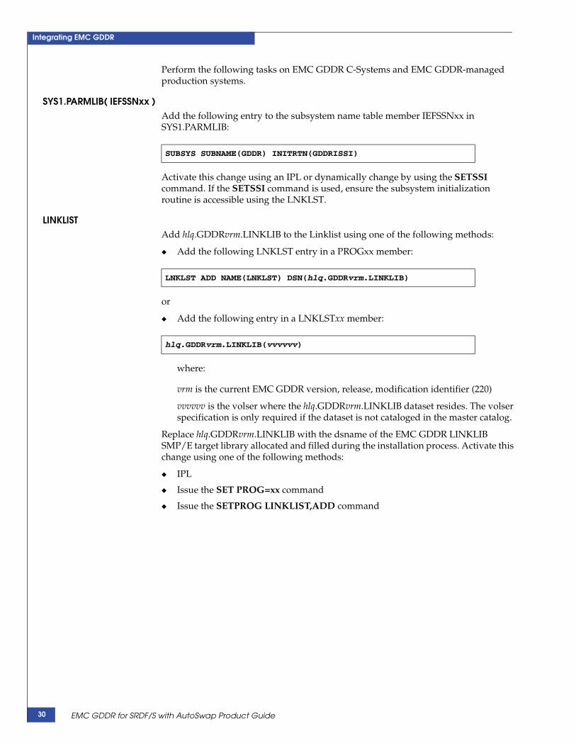
Perform the following tasks on EMC GDDR C-Systems and EMC GDDR-managed production systems.
SYS1.PARMLIB( IEFSSNxx )Add the following entry to the subsystem name table member IEFSSNxx in SYS1.PARMLIB:
Activate this change using an IPL or dynamically change by using the SETSSI command. If the SETSSI command is used, ensure the subsystem initialization routine is accessible using the LNKLST.
LINKLISTAdd hlq.GDDRvrm.LINKLIB to the Linklist using one of the following methods:
◆ Add the following LNKLST entry in a PROGxx member:
or
◆ Add the following entry in a LNKLSTxx member:
where:
vrm is the current EMC GDDR version, release, modification identifier (220)
vvvvvv is the volser where the hlq.GDDRvrm.LINKLIB dataset resides. The volser specification is only required if the dataset is not cataloged in the master catalog.
Replace hlq.GDDRvrm.LINKLIB with the dsname of the EMC GDDR LINKLIB SMP/E target library allocated and filled during the installation process. Activate this change using one of the following methods:
◆ IPL
◆ Issue the SET PROG=xx command
◆ Issue the SETPROG LINKLIST,ADD command
SUBSYS SUBNAME(GDDR) INITRTN(GDDRISSI)
LNKLST ADD NAME(LNKLST) DSN(hlq.GDDRvrm.LINKLIB)
hlq.GDDRvrm.LINKLIB(vvvvvv)
EMC GDDR for SRDF/S with AutoSwap Product Guide30

Integrating EMC GDDR
Perform ConGroup Started Task automated startupBy default, EMC GDDR does not perform ConGroup Stop/Start commands. The use of ConGroup Stop/Start commands is controlled by the Perform EMCCGRP Shutdown and Perform EMCCGRP Startup call overrides, which are available for certain scripts. When invoked, these call overrides stop and start the ConGroup started tasks running on all LPARs under EMC GDDR management; this includes C-Systems, production systems, and contingency systems.
Note: The EMC Geographically Dispersed Disaster Restart Operations Guide, Chapter 3, "EMC GDDR Operator Interface," contains descriptions of the call overrides.
EMC GDDR allows some flexibility in the way you specify the location of the software parameters for the ConGroup STCs on each LPAR.
The //CONFIG member included in the ConGroup STC startup proc contains the ConGroup startup parameters which define the consistency group. The name for the //CONFIG member can be specified in two ways:
1. Hardcode the name within the startup JCL.
If the //CONFIG member name is hardcoded within the startup JCL, then any EMC GDDR script that starts ConGroup creates a ConGroup startup command string similar to the following:
S cgstcname
where:
cgstcname is the ConGroup proc name.
2. Use a procedure substitution variable called MBR to reference a PDS member name.
If the JCL procedure substitution variable MBR is used, then any EMC GDDR script that starts ConGroup creates a ConGroup startup command string similar to:
S cgstcname,MBR=cgrp_mbr
where:
cgstcname is the ConGroup proc name.
MBR is a JCL procedure substitution variable name required by EMC GDDR which must be defined in your JCL procedure. GDDR.SAMPLIB(GDDRCGRP) shows the usage of this variable.
cgrp_mbr is the member name assigned to variable MBR to be substituted in the //CONFIG DD.
Determining which command string to use
During EMC GDDR parameter load, either of two CAOPS/MVS global variables may be loaded:
CONGroups_STC_Name.system-name=GDDRCGRPConGroups_CntlDsn.system-name=X(CGRPCAX6)
where:
system-name is the MVS system name of the system to which the statement applies.
GDDRCGRP and CGRPCAX6 are arbitrary values you choose which must match your actual ConGroup procedure name cgstcname and cgrp_mbr values.
Perform ConGroup Started Task automated startup 31

Integrating EMC GDDR
The EMC GDDR scripts will use the variables to determine which of the command strings to use:
◆ If ConGroups_CntlDsn.system-name is loaded, then EMC GDDR uses this value and builds command string:
S cgstcname,MBR=cgrp_mbr
where:
cgrp_mbr is the value assigned to procedure variable MBR.
◆ If ConGroups_CntlDsn.system-name is not loaded, then the value of cgstcname is derived from global variable CONGroups_STC_Name.system-name. EMC GDDR assumes that the // CONFIG DD member name value is hardcoded in the JCL procedure and builds the following command string:
S cgstcname
Note: “ConGroups_CntlDsn.system-name” on page 96 and “ConGroups_STC_Name.system-name” on page 97 provide detailed information regarding these parameters.
EMC GDDR for SRDF/S with AutoSwap Product Guide32

Integrating EMC GDDR
Specify EMC GDDR securityThis section details how to define the security environment required by EMC GDDR C-Systems.
EMC GDDR RACF functional groupsIt is recommended that the following RACF groups be defined to grant the appropriate access based upon job function.
Summary of RACF permissionsTable 5 provides an overview of the RACF profiles and permissions required to protect EMC GDDR resources.
Table 4 RACF functional groups
Functional group Description
GDDR$ADM For systems programmers who will install and configure EMC GDDR.For EMC GDDR administrators who will configure EMC GDDR.
GDDR$USR For operators and operations support staff who will operate EMC GDDR.
GDDR$STC For the EMC GDDR monitors, planned and unplanned processes.
Table 5 RACF permissions (1 of 2)
EMC GDDR resource owning group
EMC GDDR STC’s user group
EMC GDDR user group
Admin/Sysprog user group
GDDR$ GDDR$STC GDDR$USR GDDR$ADM
Dataset profile Access needed Access needed Access needed
hlq.GDDRvrm..LINKLIB - - ALTER
hlq.GDDRvrm..ISPMLIB - READ ALTER
hlq.GDDRvrm..OPSEXEC READ READ ALTER
hlq.GDDRvrm..ISPPLIB - READ ALTER
hlq.GDDRvrm..PROCLIB READ - ALTER
hlq.GDDRvrm..ISPSLIB READ READ ALTER
hlq.GDDRvrm..PARMLIB READ - ALTER
hlq.GDDRvrm..GLOBAL.VARS.* ALTER - ALTER
hlq.GDDRvrm..* - - ALTER
hlq.GDDRvrm.BKUPVARS.CNTL READ READ ALTER
FACILITY profile Access needed Access needed Access needed
GDDR.CBU.ACTIVE READ READ READ
GDDR.CBU.UNDO READ READ READ
GDDR.HMC.LISTOBJECTS READ READ READ
Specify EMC GDDR security 33

Integrating EMC GDDR
◆ hlq is any dataset high level qualifier, if one is used.
◆ Jes2node is the JES2 node name of the EMC GDDR C-System. The JES2 node name can be determined by issuing the the JES2 console command $DNODE,OWNNODE=YES on the appropriate EMC GDDR C-System.
The output of that JES2 command looks like this:
$HASP826 NODE(1) $HASP826 NODE(1) NAME=MFSYS3,STATUS=(OWNNODE),AUTH=(DEVICE=YES,$HASP826 JOB=YES,NET=NO,SYSTEM=YES),TRANSMIT=BOTH, $HASP826 RECEIVE=BOTH,HOLD=NONE,PENCRYPT=NO, $HASP826 SIGNON=COMPAT,DIRECT=NO,ENDNODE=NO,REST=0, $HASP826 SENTREST=ACCEPT,COMPACT=0,LINE=0,LOGMODE=, $HASP826 LOGON=0,NETSRV=0,OWNNODE=YES, $HASP826 PASSWORD=(VERIFY=(NOTSET),SEND=(NOTSET)), $HASP826 PATHMGR=YES,PRIVATE=NO,SUBNET=,TRACE=YES
The actual JES2 node name is identified on the NAME= output statement.
◆ All EMC GDDR RACF non-generic profiles should have a universal access (UACC) of NONE.
Note: Member GDDRRACF in GDDR.SAMPLIB lists the RACF commands used for EMC GDDR. These commands are used to define all required EMC GDDR resources to RACF, and permit access to EMC GDDR resources.
RACF authorization for OMVSUse of the OMVS extended attribute command (extattr) requires authorization as described by the following RACF commands:
RDEFINE FACILITY BPX.FILEATTR.PROGCTL UACC(NONE)PERMIT BPX.FILEATTR.PROGCTL CLASS(FACILITY) ID(your-user-ID) ACCESS(READ)
Where your-user-ID is the ID of the installer.
Access to this facility is needed to set the extended attributes on the gddrc* OMVS programs. This is completed at installation by the job in the #91HFS RIMLIB member.
TSOAUTH profile Access needed Access needed Access needed
OPER READ - -
SURROGAT profile Access needed Access needed Access needed
GDDR.SUBMIT READ READ READ
JESSPOOL profile Access needed Access needed Access needed
Jes2node.GDDR.*.*.*.* - READ ALTER
Table 5 RACF permissions (2 of 2)
EMC GDDR for SRDF/S with AutoSwap Product Guide34

Integrating EMC GDDR
Install EMC GDDR started proceduresTo use EMC GDDR, the EMC GDDR Event Monitor and Heartbeat Monitor tasks must be started and must remain running on the EMC GDDR C-Systems at all times. You must customize these started procedures and make them available.
Note: The EMC GDDR started procedures are required only on the EMC GDDR C-Systems. However, the EMC z/OS Console Monitor GDDRPBAL started procedure is required on all EMC GDDR managed production systems. The EMC z/OS Console Monitor GDDRCBAL started procedure is required on all EMC GDDR C-Systems.
It is recommended that automation be used to start the EMC GDDR procedures on the EMC GDDR C-Systems at system startup.
1. Update members GDDREVM and GDDRHBM so that the following DD statements point to the datasets resulting from your SMP/E installation: OPSEXEC, ISPPLIB, ISPMLIB, ISPSLIB, and SYSTSIN.
2. Make the EMC GDDR started procedures available by copying members GDDREVM and GDDRHBM from hlq.GDDRvrm.PROCLIB to SYS1.PROCLIB or equivalent library for started tasks.
3. If you plan to use customized versions of GDDR user exits, concatenate your own OPSEXEC library containing your compiled user exits ahead of hlq.GDDRvrm.OPSEXEC.
Note: “User exit programming considerations” on page 140 provides more information.
Install EMC z/OS Console Monitor started procedures1. For each C-system, make the EMC GDDRCBAL Listener STC available to the
C-systems by copying member GDDRCBAL from hlq.GDDRvrm.PROCLIB to SYS1.PROCLIB or equivalent library for started tasks.
2. Perform the following steps for each production system that requires monitoring:
a. Make the EMC GDDR GDDRPBAL STC available to the production systems by copying member GDDRPBAL from hlq.GDDRvrm.PROCLIB to SYS1.PROCLIB or an equivalent library for started tasks.
b. Make the EMC GDDR GDDRPBAL message table available to the production systems by copying member GDDRMSGR from hlq.GDDRvrm.PARMLIB to SYS1.PARMLIB or an equivalent library for parameters.
c. Update the STC procedure GDDRPBAL DD statement "MESSAGES" with the dataset containing the GDDRMSGR member.
3. Complete the started task installation by making the changes to the subsystem name table member IEFSSNxx in SYS1.PARMLIB and LINKLST specified in “Update system parameter files” on page 29.
Install EMC GDDR started procedures 35

Integrating EMC GDDR
Customize CA-OPS/MVS for EMC GDDRThis section describes updates that are required in order to make EMC GDDR available as a CA-OPS/MVS user application.
Include EMC GDDR libraries in OPSVIEW REXX execEMC GDDR libraries must be added to the OPSVIEW startup REXX exec (often OPSVLBDF). Follow these guidelines:
◆ Include hlq.GDDRvrm.ISPMLIB as the first library in the OPSMLIB concatenation.
◆ Include hlq.GDDRvrm.ISPSLIB as the first library in the OPSSLIB concatenation.
◆ Include hlq.GDDRvrm.ISPPLIB as the first library in the OPSPLIB concatenation.
◆ Include opshlq.USSLOAD in the OPSLLIB concatenation.
◆ Include hlq.GDDRvrm.OPSEXEC as the first library in the OPSEXEC concatenation.
◆ If you plan to use customized versions of EMC GDDR user exits, concatenate your own OPSEXEC library containing your compiled user exits ahead of GDDR.OPSEXEC.
Note: “User exit programming considerations” on page 140 provides more information.
◆ Add a GDDRSLIB DD statement pointing to the same datasets as the OPSSLIB concatenation.
Note: The hlq.GDDRvrm.LINKLIB library is not needed in the OPSLLIB concatenation, but must be included in the system linklist concatenation.
Make EMC GDDR AOF rules available to CA-OPS/MVS1. Update the CA-OPSVS initialization parameters found in
CAOPS.V115.OPS.CNTL with the distributed EMC GDDR rules found in hlq.GDDRvrm.AOFRULES. Update the parameters RULEPREFIX, RULESUFFIX with the required values.
2. Repeat this for each C-System. “Install EMC z/OS Console Monitor started procedures” on page 35 provides more information. The z/OS Console Monitor propagates messages associated with events of interest to the GDDR Event Monitor.
Change CA-OPS/MVS access rulesThe CA-OPS/MVS access rules must be changed in order to allow the following:
◆ EMC GDDR to update global variables and use the CA-OPS/MVS OPSCMD function
◆ CA-OPS/MVS OPSOSF address spaces to use the CA-OPS/MVS OPSWTO function
In your hlq.GDDRvrm.AOFRULES dataset, add the lines of code shown below to members GLOBAL, OPSCMD and OPSWTO, which create SEC event rules.
EMC GDDR for SRDF/S with AutoSwap Product Guide36

Integrating EMC GDDR
Note: In the sample code below, gddr_racf_userid is the RACF user ID under which the EMC GDDR started procedures and processes will run. opsosf_racf_userid is the RACF user ID under which the OPSOSF started procedure will run.
GLOBAL and OPSCMD member
IF userid = "gddr_racf_userid" THEN RETURN "ACCEPT"
OPSWTO member
IF userid = "gddr_racf_userid" THEN RETURN "ACCEPT"IF userid = "opsosf_racf_userid" THEN RETURN "ACCEPT"
Customize EMC GDDR user exit 7 (optional) Customize user exit 7, if necessary, as described in Appendix A, “EMC GDDR User Exits.” Then copy the customized exit to the appropriate AOFRULES dataset.
Update CA-OPS/MVS started procedure OPSOSF
CAUTION!These changes to OPSOSF must only be made on the EMC GDDR C-Systems.
To the OPSOSF CA-OPS/MVS started procedure, add the OPSEXEC ddname if not already used, specifying the following EMC GDDR SMP/E target library:
GDDR.OPSEXEC
If there is already an OPSEXEC ddname, insert this library as the first library in the concatenation.
Customize the REXX exec defining the specifications for the CA-OPS/MVS copy on each C-System
This REXX is pointed to by the OPSTART1 member in the PDS referenced on the SYSPROC DD statement in the OPSMAIN started procedure.
Add the following statement, or update an already existing REXXMAXQUEUE value as shown:
T = OPSPRM_SET("REXXMAXQUEUE","6000")
Update the Unix system service directoryAdd the following directories to the PATH and LIBPATH statements to the OPSUSS STC parameter file: These statements allow EMC GDDR to load and run the HMC interface:
◆ /gddr
◆ /gddr/source (home for HMC API)
Activate this change by recycling the OPSUSS started procedures.
Customize CA-OPS/MVS for EMC GDDR 37

Integrating EMC GDDR
Note: To run the EMC GDDR HMC programs directly from the OMVS shell, add the following directories to the PATH and LIBPATH statements in the /etc/profile file:
/gddr/gddr/source
Below are statement examples to accomplish this:
PATH=$PATH:/gddr:/gddr/source:LIBPATH=$LIBPATH:/gddr:/gddr/source:
Define the EMC GDDR monitoring started tasks to CA-OPS/MVS SSMTo ensure that the EMC GDDR Event Monitor started task (GDDREVM) and the EMC GDDR Heartbeat Monitor started task (GDDRHBM) are kept running at all times on the EMC GDDR C-Systems, put them under the control of CA-OPS/MVS SSM (System State Manager) as follows:
1. Create the STCTBL RDF table or modify the existing table so that only the following entries exist for the EMC GDDR started procedures.
2. Create the STCTBL_ACT RDF table or modify the existing table so that only the following entries exist for the EMC GDDR started procedures.
Use OPSVIEW Primary Option 2.6 - Relational Table Editor for RDF to create the tables if they do not exist. Create the STCTBL table with the STC STATEMAN table model and create the STCTBL_ACT table with the ACTION STATEMAN table model. Refer to Chapter 11, “Using the Relational Data Framework, Table Management Operations,” in the Unicenter CA-OPS/MVS Event Management and Automation User Guide or contact your CA-OPS/MVS administrator for more assistance.
Name/Jobname Desired_State Mode Type PREREQ
GDDREVM UP A GDDREVM JES2 TCPIP
GDDRHBM UP A GDDRHBM JES2 TCPIP
GDDRCBAL UP A GDDRCBAL EMC ResourcePak Base
ACTION_CURRENT ACTION_DESIRED ACTION_RES_TYPE ACTION_TEXT
DOWN UP GDDREVM …START &JOBNAME
DOWN UP GDDRHBM …START &JOBNAME
UP DOWN GDDREVM …CANCEL &JOBNAME
UP DOWN GDDRHBM …CANCEL &JOBNAME
DOWN UP GDDRCBAL …START &JOBNAME
UP DOWN GDDRCBAL …CANCEL &JOBNAME
EMC GDDR for SRDF/S with AutoSwap Product Guide38

Integrating EMC GDDR
Merge CA-OPS/MVS user applications
ISPF panel OPSUSER, provided in installation dataset GDDR.ISPPLIB, provides access to EMC GDDR’s online facilities. If you already have user applications accessed through a panel of the same name, you will need to merge the two panels into one panel to provide access to the EMC GDDR online facilities as well as to your existing user applications.
If OPS/MVS is already in use in your environment, you will need to modify the OPSUSER panel to include the EMC GDDR application. You can do this by adding the following EMC GDDR options:
1,'PGM(OI) PARM(GDDROPS1)'
2,'PGM(OI) PARM(GDDROPO1)'
3,'PGM(OI) PARM(GDDRPROF)'
Update CA-OPS/MVS CCI parameters
1. On each C-System, add the following entries for the new C-System to the CA Event Notification/CCI parameter member CCIssssssss:
• NODE( …add appropriate parameters for the new C-System… )
• CONN,ssssssss
where ssssssss is the MSF ID or the MVS system name of the new C-System.
• NODE( …add appropriate parameters for the new system… )
• CONN, ssssssss
where ssssssss is the MSF ID or the MVS system name of the new C-System.
2. If CA-OPS/MVS is installed on the production systems, add the following entries for the new C-System to the CA Event Notification/CCI parameter member CCIssssssss:
• NODE( …add appropriate parameters for the new C-System… )
• CONN,ssssssss
where ssssssss is the MSF ID or the MVS system name of the new C-System.
• NODE( …add appropriate parameters for the new system… )
• CONN, ssssssss
where ssssssss is the MSF ID or the MVS system name of the new C-System.
Customize CA-OPS/MVS for EMC GDDR 39

Integrating EMC GDDR
Modify CA-OPS/MVS to use the GDDRMSG tableExternal text resides in an EMC GDDR PARMLIB member called GDDRMSG. At execution time, the external text information is stored in a CA-OPS/MVS SQL table called GDDRMSG. The GDDRMSG table is created when external text is requested by EMC GDDR code and the GDDRMSG table does not exist.
EMC GDDR loads the GDDRMSG table using the EMC GDDR PARMLIB member GDDRMSG. As a result, the EMC GDDR PARMLIB PDS must be specified within the OPSMLIB DD in the following items:
◆ The exec that takes you to CA-OPS/MVS using TSO ISPF =6. For example, the following are changes in CAOPS.OPS115T.SAMPLES(OPSVIEWX):
"ALLOC FI(OPSMLIB) REUSE SHR DA('"usrpfx0".PARMLIB'" , "'"usrpfx1".PARMLIB'" , "'"usrpfx2".PARMLIB'" , "'"usrpfx3".PARMLIB'" , "'"prefix".OPSMLIB')"
◆ The skeletons that execute scripts. For example, the following are changes in SYS3.DEVELOP.PROCLIB(GDDRPROC):
//OPSMLIB DD DISP=SHR,DSN=&USRPFX1..PARMLIB // DD DISP=SHR,DSN=&USRPFX2..PARMLIB // DD DISP=SHR,DSN=&USRPFX3..PARMLIB // DD DISP=SHR,DSN=&USRPFX4..PARMLIB
Note: The ISPMLIB DD requirement is only needed the first time that the CA-OPS/MVS GDDRMSG SQL table is built. This table will persist until it is deleted (CA-OPS/MVS Opsview, option 2.6) or until CA-OPS/MVS is recycled.
The GDDRMSG table is built in each CA-OPS/MVS environment. For example, if you have 2 LPARs, x17 and x18, the table will be built on each one, as required. The EMC GDDR PARMLIB dataset must be accessible to each LPAR that will execute EMC GDDR.
Temporary changes to the external text can be made using CA-OPS/MVS Opsview, option 2.6. Permanent changes can be made to the GDDRMSG PARMLIB member and then incorporated into the EMC GDDR execution environment by deleting the GDDRMSG SQL table so that it will be automatically rebuilt.
EMC GDDR for SRDF/S with AutoSwap Product Guide40

Integrating EMC GDDR
Configure EMC GDDRThe remaining tasks to be completed before you may begin using EMC GDDR are performed using EMC GDDR online facilities. The task descriptions in this section consequently include references to the relevant online procedures.
Note: It is suggested that you review the introductory procedures described in Chapter 3, ”Using EMC GDDR Online Facilities” prior to performing the tasks listed in this section.
Allocate the parameter backup dataset
1. Allocate the dataset that will be used to contain backups of EMC GDDR parameters.
Backups of EMC GDDR global variables are made when EMC GDDR parameters are loaded, when the EMC GDDR Heartbeat Monitor starts, and when the EMC GDDR administrator procedure ‘Create GDDR Parameter Backup’ is invoked.
2. Customize and run the job in member GDDRABDS in hlq.GDDRvrm.SAMPLIB. Ensure it has run successfully.
Note: Ensure that the EMC GDDR parameter GDDRVAR_BACKUP is set to the name of the dataset you allocate.
Customize member GDDRPROCCustomize member GDDRPROC in GDDR.PROCLIB used to run EMC GDDR scripts to your environment:
1. Update the STEPBLIB DD statement to include the following load libraries:
• hlq.GDDRvrm.LINKLIB resulting from your EMC GDDR SMP/E installation
• Your SRDF Host Component load library
• Your ResourcePak Base load library
• Your Consistency Group load library
• Your TimeFinder/Mirror load library, if you use TimeFinder/Mirror
• Your TimeFinder/Clone Mainframe SNAP Facility, if you use TFCMSF
• Your ISPF load library
• Your CA-OPS/MVS load library
2. Make sure the following DD statements refer to the EMC GDDR datasets resulting from your GDDR SMP/E installation:
• OPSEXEC
• ISPPLIB
• ISPMLIB
• ISPSLIB
Configure EMC GDDR 41

Integrating EMC GDDR
3. If you plan to use cutomized versions of GDDR User Exits, concatenate your own OPSEXEC library containing your compiled User Exits ahead of GDDR.OPSEXEC.
Note: “User exit programming considerations” on page 140 provides more information.
Prepare and load EMC GDDR parameters
Examine input parameter information The parameters described in Chapter 4, ”EMC GDDR Parameters,” control which systems and devices EMC GDDR is enabled to manage at your site. They will also specify how EMC GDDR handles conditions requiring the use of EMC recovery and business continuity facilities.
Note: Before continuing, a careful examination of the parameters that you may specify and how they affect EMC GDDR processing is recommended.
Edit the parameter input file1. Reach the CA-OPS/MVS User Applications panel by following the procedure
described on page 52, and select option 1 to view the Administrator Primary Options Menu as shown in Figure 3.
Note: Asterisks appear as the current EMC GDDR state values on the right. Once initialization is complete, subsequent display of this menu will include current state values.
Figure 3 EMC GDDR Administrator Primary Options Menu
------------------ GDDR - Administrator Primary Options Menu ------------------ Option ===> A Automation Toggle GDDR automation On/Off Current Master: ZOSESYS4 C Config View GDDR configuration Primary Site: DC2 H HMC Manage HMC Primary DASD: DC2 J JobVals View or change default job values Automation: ON M MsgOut Specify GDDR message output options Planned script: None P Parms Update GDDR parameters Unplanned script: None Q Queue Manage GDDR internal command queue R ManagePrms Manage GDDR parameters S Systems Configure GDDR production systems Enter a GDDR administrator option and press <Enter> Press <F3> to return to CA-OPS/MVS user applications EMC Geographically Dispersed Disaster Restart 02.02.00 Copyright © 2007, 2008 EMC Corporation
EMC GDDR for SRDF/S with AutoSwap Product Guide42

Integrating EMC GDDR
2. To begin initial parameter customization and load, select option P and press Enter.
The Specify GDDR ISPF Skeleton Dataset panel shown in Figure 4 displays.
Figure 4 Specify GDDR ISPF Skeleton Dataset panel
Note: You will initially be presented with several panels requiring you to enter the names of EMC GDDR datasets. These panels will no longer be required once the EMC GDDR parameters have been initialized.
Whenever a dataset name is required, you must specify a fully-qualified dataset name. TSO prefixing does not apply to any dataset name specified within EMC GDDR.
3. Enter the name of the ISPSLIB dataset created when you downloaded the install cartridge, and press Enter.
The Specify GDDR Procedure Library panel shown in Figure 5 displays.
Figure 5 Specify GDDR Procedure Library panel
----------- GDDR Administration - Specify GDDR ISPF Skeleton Dataset ----------Command ===> Specify the name of a dataset containing the GDDR file tailoring skeletons to use for initial parameter load. (This dataset often has the low-level qualifier 'ISPSLIB' or 'SKELS'.) Dataset name ===> ____________________________________________ Press <Enter> when ready. You may press <F3> to cancel the parameter load.
------------- GDDR Administration - Specify GDDR Procedure Library ------------Command ===> Specify the name of a dataset containing the GDDR cataloged procedure GDDRPROC to use for initial parameter load. (This dataset often has the low-level qualifier 'PROCLIB'.) Dataset name ===> ___________________________________________ Press <Enter> when ready. You may press <F3> to cancel the parameter load.
Configure EMC GDDR 43

Integrating EMC GDDR
4. Enter the name of the PROCLIB dataset created when you downloaded the install cartridge and press Enter.
The Specify GDDR Parameter Dataset panel shown in Figure 6 displays.
Figure 6 Specify GDDR Parameter Dataset panel
5. Enter the name of the PARMLIB dataset created when you downloaded the install cartridge and press Enter.
A Load GDDR Parameters panel such as the example shown in Figure 7 displays.
Figure 7 Load GDDR Parameters panel
------------- GDDR Administration - Specify GDDR Parameter Dataset ------------Command ===> Specify the name of a dataset containing one or more members that specify GDDR parameters. Dsname ===> ____________________________________________ Press <Enter> when ready. You may press <F3> to cancel the request.
------------- GDDR Administration - Load GDDR Parameters --- Row 1 to 4 of 4 Command ===> Scroll ===> CSR The following row commands may be entered: Current Master: SYS4 S Select a parameter member to load Primary Site: DC1 U Deselect a selected member Primary DASD: DC1 E Edit a parameter member Automation: ON Additional commands are available. Press <F1> to view a complete list. Enter parameter dataset ===> GDDR.GDDR220.PARMLIB Last initialization load from GDDR.GDDR220.PARMLIB(GDDRAUTO) When ready, press <F3> to submit job to load specified or selected members Enter CANCEL to exit without loading any parameter members Sel Member Description Selected? --- -------- ------------------------------------------------- --------- _ GDDRAUTO
EMC GDDR for SRDF/S with AutoSwap Product Guide44

Integrating EMC GDDR
6. To edit any of the parameter members, enter an E next to a member name and press Enter.
You will be placed into an edit session for parameter member GDDRAUTO and view the panel shown in Figure 8.
Figure 8 Parameter Member Edit Session panel
7. Make changes to the parameter member to reflect your configuration and your installation preferences in accordance with decisions that were made in “Examine input parameter information ” on page 42.
8. When ready, save the member and end the edit session. You will be returned to to the Load GDDR Parameters panel (Figure 7 on page 44).
Note: Supplied parameter member GDDRSAMP is a copy of GDDRAUTO. It provides a base point for your parameter member changes.
ISREDDE2 GDDR.GDDR220.PARMLIB(GDDRAUTO) - 01.14 Columns 00001 00072 Command ===> Scroll ===> PAGE ****** ***************************** Top of Data ******************************000001 ********************************************************************* 000002 ******* GENERAL CONFIGURATION ******* 000003 ********************************************************************* 000004 * LAST UPDATE 000005 * 000006 ********************************************************************* 000007 * CONFIGURATION CHARACTERISTICS * 000008 ********************************************************************* 000009 GDDR.CONFIG=2SITE,SRDFS,AUTOSWAP 000010 ********************************************************************* 000011 * CONGROUP START-UP MEMBER * 000012 ********************************************************************* 000013 000014 CONGROUPS_CNTLDSN.ZOSESYS4=X(CGRPAUTO) 000015 CONGROUPS_CNTLDSN.ZOSESYS1=X(CGRPAUTO) 000016 CONGROUPS_CNTLDSN.ZOSESYS5=X(CGRPAUTO) 000017 CONGROUPS_CNTLDSN.ZOSESYS6=X(CGRPAUTO) 000018 000019 *********************************************************************
Configure EMC GDDR 45

Integrating EMC GDDR
Run a test load of the updated parameter fileParameter load processing allows you to validate the parameter input you have prepared without performing any global variable updates. For the initial parameter load, this is highly recommended.
1. On the Load GDDR Parameters panel, select the member(s) to load and press PF3.
The Confirm GDDR Parameter Load panel displays as shown in Figure 9.
Figure 9 Confirm GDDR Parameter Load panel
2. On the Confirm GDDR Parameter Load panel, enter job statement information and specify Y or N for the following options:
• Should this load job replace all current parameter values?
• Should this load job run in test mode and do no updates?
• Should parameter update proceed even with MSF links down?
When you press Enter, the parameter load will be submitted.
3. When the job completes, examine the output, proceeding as follows:
a. Scan for the message “Parameter syntax checking successful". If not present, find all occurrences of “error”, correct the errors indicated, and resubmit the test load job. Otherwise, continue.
b. Scan for the message “Reference check successful”. If not present, find all occurrences of “error”, correct the errors indicated, and resubmit the test load job. Otherwise, continue.
c. Scan for the phrase “assigned default” to determine the default values that have been generated. Ensure these defaults are acceptable.
-------------- GDDR Administration - Confirm GDDR Parameter Load --------------Command ===> A GDDR parameter load job is being scheduled using the following members of dataset GDDR.PARMLIB GDDRAUTO To complete job preparation, reply Y or N to each of the following. Should this load job replace all current parameter values? ===> N Should this load job run in test mode and do no updates? ===> Y Should parameter update proceed even with MSF links down? ===> N Enter or change the job statement //GDDRJOB1 JOB (0),'P',MSGLEVEL=(1,1),CLASS=S,MSGCLASS=J, // NOTIFY=GDDRUSR //* //* Press <Enter> when ready. Press <F3> to return without submitting job.
EMC GDDR for SRDF/S with AutoSwap Product Guide46

Integrating EMC GDDR
Load the EMC GDDR parametersWhen the parameter values are satisfactory and the validation run is successful, you are ready to perform your first load of the EMC GDDR parameters:
1. Reach the Load GDDR Parameters panel (shown in Figure 7 on page 44), enter the Load command, and press Enter as described above.
This time, however, on the Confirm GDDR Parameter Load panel you must specify the values indicated at the right for the following options:
a. Should this load job replace all current parameter values? Y
b. Should this load job run in test mode and do no updates? N
c. Should parameter update proceed even with MSF links down? N
2. When you press Enter, the parameter load job will be submitted.
3. When the job completes, ensure that it did so with completion code 0. Then verify that the correct global variable values were assigned and that updates were successful on all C-Systems by finding the following message for each remote C-System:
GDDP022I Updates complete on MSF id msfid
Then look for the following messages at the end of the listing:
GDDP022I Updates complete on local system
GDDP135E Processing complete, rc = 0
If these messages are present, the parameter load has been successful. Otherwise, determine the reasons why not, correct any errors or environmental conditions, and rerun the parameter load job.
Specify EMC GDDR job defaults
Upon detecting certain unexpected events, specifically a ConGroup trip or a CAX swap condition, EMC GDDR may submit a script job automatically to recover from the situation that caused the event. Because there is no opportunity for an operator to edit such a job stream before it is submitted, EMC GDDR performs job customization using the job default values entered in this step.
Specify the job default values to use for EMC GDDR jobs submitted internally by performing the procedure described in “Option J — JobVals: View or change default job values” on page 58.
Configure the EMC GDDR HMC interface
Perform the following procedures to configure the EMC GDDR Hardware Management Console (HMC) interface:
◆ Establish system connectivity to HMC consoles
◆ Download and configure the HMC API DLL
◆ Add HMC console communities
◆ Specify HMC community names to EMC GDDR
◆ Link-edit the HMC API DLL
◆ Verify the EMC GDDR HMC interface
Configure EMC GDDR 47

Integrating EMC GDDR
Establish system connectivity to HMC consolesEstablish that connectivity exists between each C-System and its HMC console. You may do so by attempting to ping the console from the C-System. Use the following procedure for each site:
1. Log on to TSO and enter READY mode.
2. Enter the following command:
ping ip-address
where ip-address is the IP address you specified as the value of the HMC.siteid EMC GDDR parameter for the site you are currently testing.
Download and configure the HMC API DLLPerform the following steps:
1. Download the z/OS DLL containing the C/C++ language HWMCA Management API. This executable can be downloaded from IBM Resource Link. At this site, go to Services, then navigate to the z/OS API page, and download HWMCAAPI.
2. FTP the HWMCAAPI DLL in binary to the /gddr/source directory on all C-Systems.
3. Add the p attribute to HWMCAAPI using the following shell command:
extattr +p HWMCAAPI
For more information, see “RACF authorization for OMVS” on page 34.
4. Link edit the HWMCAAPI into opshlq.USSLOAD loadlib. JCL is provided by CA in hlq.CNTL(INSTHWMC). More information is located in the Unicenter CA-OPS/MVS Event Management and Automation Administrator Guide r11.5, "Initiate an Action through CPC and LPAR Names".
5. Add opshlq.USSLOAD to linklist.
Add HMC console communitiesAdd communities on your HMC console to support the EMC GDDR connection. Perform the following steps:
1. Using an HMC administrator user ID, start the SNMP configuration task (under console actions in the views area of the console).
2. Each HMC console must have a community name defined to be used by the site’s C-System. Add community names using the following guidelines:
• Name is the community name. EMC GDDR uses the system name of the connecting C-System, set to lowercase, as the default community name when initializing a connection with an HMC console. To use a different HMC community name, use the procedure described in “Option 2: Specify HMC community names” on page 57 to specify the name to EMC GDDR.
• Address specifies the IP address of the C-System that will use the community name specified by Name.
• Network Mask should be 255.255.255.255
• Protocol must be UDP.
• Access Type must be Read/Write.
EMC GDDR for SRDF/S with AutoSwap Product Guide48

Integrating EMC GDDR
3. If necessary, reboot the HMC service for the HMC consoles whose community names were changed or added.
Note: The IBM System z Application Programming Interfaces Guide, SB10-7030-09, Chapter 6, "Configuring for the Data Exchange APIs," provides information to assist you with HMC or Support Element Settings configuration tasks.
Specify HMC community names to EMC GDDREMC GDDR’s HMC interface requires that the community name used by EMC GDDR matches the community name specified for the generation of HMC support.
If, when configuring the HMC console as described above, you specified a community different from the system name of the C-System at the site where the HMC console is defined, you must specify this community name to EMC GDDR. To do so, follow the procedure described in “Option 2: Specify HMC community names” on page 57.
Verify the EMC GDDR HMC interfaceTo verify that the preceding steps have been performed correctly, test EMC GDDR’s ability to access the HMC consoles by performing the procedure described in “Option1: Discover HMC objects” on page 56. This should complete successfully, and the C-System HMC consoles should appear in the display.
If an error occurs, review the HMC interface install procedure.
Configuring multiple EMC GDDR parameter members (optional)The EMC-supplied parameter GDDRAUTO contains models for all the parameter statements. Since your initial parameter load will include all required parameter statements, as well as all optional parameter statements for which you require values different from the defaults, your initial parameter load procedure provides for editing only a single member.
For subsequent parameter load processing, you may choose to utilize the multiple-member feature. This feature allows you to keep parameter statements in different parameter library members, grouping parameters as you want. Any number of members, any valid member names, and any distribution of parameters among the members are allowed.
To utilize this feature, create the members as needed from the member you used for your initial parameter load. When you perform subsequent parameter maintenance, enter the name of the dataset containing the members, with no members, in the ‘Enter parameter dataset ===>’ field on the Load GDDR Parameters panel (shown in Figure 7 on page 44) and follow the procedure described in “EMC GDDR ISPF profiles” on page 81.
Configure EMC GDDR 49

Integrating EMC GDDR
Modifying EMC GDDR user exits (optional)
EMC GDDR provides exit points that you may use to augment EMC GDDR facilities. Sample exits are provided in the hlq.GDDRvrm.SAMPLIB distribution library. You may modify these exits, or write your own, following the guidelines presented in Appendix A, “EMC GDDR User Exits.” The exit points are the following:
◆ GDDRUX01 is called from planned or unplanned event scripts at a point appropriate for starting production mainframe workloads.
◆ GDDRUX02 is called from planned or unplanned scripts at a point appropriate for shutting down production mainframe workloads.
◆ GDDRUX03 is called from planned or unplanned scripts at a point appropriate for starting distributed production workloads.
◆ GDDRUX04 is called from planned or unplanned scripts at a point appropriate for stopping distributed production workloads.
◆ GDDRUX05 is called each time an EMC GDDR message is about to be issued at a point appropriate for creating alerts such as an SNMP event.
◆ GDDRUX06 is invoked each time an EMC GDDR message is about to be issued. Using this exit, you may process the message in any of several ways, suppress it entirely, or suppress it and substitute a different message.
◆ GDDRUX07 is called from each message rule during the rule initialization phase, permitting you to allow or bar the enabling of each message rule.
EMC GDDR for SRDF/S with AutoSwap Product Guide50

3Invisible Body Tag
This chapter describes the EMC GDDR online facility interface. Topics are:
◆ Introduction .................................................................................................................... 52◆ EMC GDDR administrator facilities............................................................................ 53◆ EMC GDDR ISPF profiles ............................................................................................. 81◆ Using OPSVIEW facilities for EMC GDDR administration..................................... 82
Using EMC GDDROnline Facilities
Using EMC GDDR Online Facilities 51

Using EMC GDDR Online Facilities
IntroductionEMC GDDR online facilities permit z/OS system programmers to perform configuration and administration tasks and operators to perform operator functions.
To use the EMC GDDR online facilities interface, you first must access the CA-OPS/MVS OPSVIEW Primary Options menu shown in Figure 10.
Note: Many installations provide option OPS on the TSO Primary Options menu for this purpose. Your installation may provide a different method for reaching the CA-OPS/MVS OPSVIEW Primary Options menu.
Figure 10 CA-OPS/MVS OPSVIEW Primary Options panel
On the CA-OPS/MVS Primary Options menu, select option U – User-defined applications and press Enter to view a CA-OPS/MVS User Applications panel such as that shown in Figure 11.
Figure 11 CA-OPS/MVS User Applications panel
Note: You may have other CA-OPS/MVS user applications in your system. If so, they will appear on this panel as well.
CA-OPS/MVS ------ SYS2 --- OPSVIEW Primary Options Menu ----- Subsystem OPSS Option ===> 0 Parms Set OPSVIEW and ISPF default values User ID - GDDUSR1 1 OPSLOG Browse OPSLOG Time - 12:08 2 Editors AOF Rules, REXX programs, SQL Tables Release - 11.5 3 Sys Cntl Display/Modify System Resources SP - 1 4 Control Control CA-OPS/MVS 5 Support Support and Bulletin Board information 6 Command Enter JES2/MVS/IMS/VM commands directly 7 Utilities Run CA-OPS/MVS Utilities A AutoMate Unicenter CA-AutoMate rules edit and control I ISPF Use ISPF/PDF services S SYSVIEW Unicenter CA-SYSVIEW T Tutorial Display information about OPSVIEW U User User-defined applications X Exit Exit OPSVIEW Unicenter CA-OPS/MVS Event Management and Automation Copyright © 2006 CA. All rights reserved. Press END or enter X to terminate OPSVIEW
OPSUSER ----------------- CA-OPS/MVS User Applications ------------------------ Option ===> 1 Admin Perform GDDR administrator functions 2 Oper Perform GDDR operator functions 3 Profile Update personal GDDR ISPF profile variables Type an option number and press <Enter> to enter a user application Press <F3> to return to the OPSVIEW Primary Options Menu
EMC GDDR for SRDF/S with AutoSwap Product Guide52

Using EMC GDDR Online Facilities
EMC GDDR administrator facilitiesEMC GDDR administrator facilities are accessed by selecting option 1 – Perform GDDR administrator functions on the CA-OPS/MVS User Applications panel (Figure 11 on page 52) and pressing Enter. When you enter this option, the following panel displays:
Figure 12 GDDR Administrator Primary Options panel
Control fieldsAt the right side of the panel, the GDDR Administrator Primary Options menu displays the current settings for several EMC GDDR control values.
Note: The fields described below also appear on a number of other EMC GDDR panels.
Current Master
Shows the name of the C-System that currently owns the EMC GDDR master function. As a general rule, the master C-System is located at the opposite site from the business applications. Thus, if the business applications are running at site DC1, the master C-System will be the C-System at site DC2.
Most EMC GDDR administrator actions are allowed only when logged onto the master C-System.
Primary Site
Indicates on which site's CPUs the business applications are currently running.
Primary DASD
Indicates the site at which the R1 DASD currently reside. Generally, the sites indicated by Primary Site and Primary DASD should be the same.
Automation
Indicates the current availability of EMC GDDR automation functionality. Automation can be set to either ON or OFF.
Planned script
Planned script indicates which Planned script, if any, is currently in progress. Note that a Planned script is considered to be in progress if it has been started but has not yet completed successfully; in this case, it is eligible for restart.
If no Planned script is currently in progress, ‘None’ is displayed in this field.
------------------ GDDR - Administrator Primary Options Menu ------------------ Option ===> A Automation Toggle GDDR automation On/Off Current Master: ZOSESYS4 C Config View GDDR configuration Primary Site: DC2 H HMC Manage HMC Primary DASD: DC2 J JobVals View or change default job values Automation: ON M MsgOut Specify GDDR message output options Planned script: None P Parms Update GDDR parameters Unplanned script: None Q Queue Manage GDDR internal command queue R ManagePrms Manage GDDR parameters S Systems Configure GDDR production systems
Enter a GDDR administrator option and press <Enter> Press <F3> to return to CA-OPS/MVS user applications
EMC Geographically Dispersed Disaster Restart 02.02.00 Copyright © 2007, 2008 EMC Corporation
EMC GDDR administrator facilities 53

Using EMC GDDR Online Facilities
Unplanned script
Unplanned script indicates which Unplanned script, if any, is currently in progress. Note that an Unplanned script is considered to be in progress if it has been started but has not yet completed successfully; in this case, it is eligible for restart.
If no Unplanned script is currently in progress, ‘None’ is displayed in this field.
Administrator optionsAt the left side of the panel, a series of administrator options are listed. To invoke one of the following actions, enter the appropriate option on the command line and press Enter. These options are described in the following sections.
Option A — Automation: Toggle GDDR Automation On/Off
Note: This option is valid only on the master C-System.
When you select the EMC GDDR administrator option Toggle GDDR Automation On/Off, the ability of EMC GDDR operators to run Planned scripts is modified, changing to ON when it is currently OFF and changing to OFF when it is currently ON. The displayed value of the automation setting on the right of the panel reflects the change immediately.
When you set EMC GDDR automation ON, EMC GDDR operators will be able to run both Planned and Unplanned scripts. When you set EMC GDDR automation OFF, EMC GDDR operators will not be able to run Planned scripts, but Unplanned scripts will still run.
After entering option A, messages similar to the following appear:
GDDR373I GDDR Broadcasting new value for AUTOMATION.FLAG GDDR739I GDDR -> Set GDDR Broadcasting new value for AUTOMATION.FLAG at SYS1 GDDR739I GDDR -> Set GDDR Broadcasting new value for AUTOMATION.FLAG at SYS3
The Administrator Primary Options menu indicates the automation setting at the bottom of the display:
------------------ GDDR - Administrator Primary Options Menu ------------------ Option ===> A Automation Toggle GDDR automation On/Off Current Master: ZOSESYS4 C Config View GDDR configuration Primary Site: DC2 H HMC Manage HMC Primary DASD: DC2 J JobVals View or change default job values Automation: OFF M MsgOut Specify GDDR message output options Planned script: None P Parms Update GDDR parameters Unplanned script: None Q Queue Manage GDDR internal command queue R ManagePrms Manage GDDR parameters S Systems Configure GDDR production systems Enter a GDDR administrator option and press <Enter> Press <F3> to return to CA-OPS/MVS user applications EMC Geographically Dispersed Disaster Restart 02.02.00 Copyright © 2007, 2008 EMC Corporation +------------------------------------------------------------------+ | Automation has been set OFF, planned scripts are now unavailable | +------------------------------------------------------------------+
EMC GDDR for SRDF/S with AutoSwap Product Guide54

Using EMC GDDR Online Facilities
Option C — Config: View GDDR configuration
When you select the EMC GDDR administrator option View GDDR configuration, the following panel displays:
Figure 13 View GDDR Configuration panel
---------------- GDDR Administration - View GDDR Configuration ---------------- Command ===> Sites: DC1, DC2 Features: SRDF/S, AUTOSWAP, No FBA Devices C-Systems: At DC1, C-System is SYS4 with MSF id SYS4 At DC2, C-System is SYS3 with MSF id SYS3 Press <F3> to return to the previous menu
EMC GDDR administrator facilities 55

Using EMC GDDR Online Facilities
Option H — HMC: Manage HMC
When you select the EMC GDDR administrator option Manage HMC, the following panel displays:
Figure 14 HMC Management Options panel
On the HMC Management Options menu, type an option number and press Enter. The options are described below.
Option1: Discover HMC objectsTo discover HMC objects accessible to EMC GDDR, specify option 1. When you do so, a ‘please wait’ pop-up dialog such as the following is displayed and HMC object discovery is activated:
-------------- GDDR Administration - HMC Management Options Menu -------------Option ===> 1 HMC objects Discover HMC objects Current Master: SYS3 2 Community names Specify HMC community names Primary Site: DC2 Primary DASD: DC2 Automation: ON Enter an HMC management option and press <Enter> Press <F3> to return to the Administrator Primary Options Menu
------------- GDDR Administration - HMC Management Options Menu ------------ Option ===> 1 1 HMC objects Discover HMC objects Current Master: SYS3 2 Community names Specify HMC community names Primary Site: DC2 Primary DASD: DC2 Automation: ON Enter an HMC mana +------- Discovering HMC Objects ---------+ Press <F3> to ret | | | Discovering HMC objects at site DC1 | | | | *** PLEASE WAIT *** | | | +-----------------------------------------+
EMC GDDR for SRDF/S with AutoSwap Product Guide56

Using EMC GDDR Online Facilities
When the discovery operation completes, you are presented with the HMC Discovery Results panel containing a scrollable display such as the following:
Figure 15 HMC Discovery Results panel
When you are finished examining the results of the discovery operation, press F3 to return to the HMC Management Options panel (Figure 14 on page 56).
Option 2: Specify HMC community namesTo specify the community names that EMC GDDR uses when establishing a session with an HMC console, specify option 2. A Specify HMC Community Names panel such as the following is presented.
Figure 16 Specify HMC Community Names panel
On the Specify HMC Community Names panel, you may enter the community names EMC GDDR is to use in place of the default, which for each system/site combination is the system name.
--------------- GDDR Administration - HMC Discovery Results --- Row 1 of 203Command ===> Enter <F3> to return to the HMC Management Options menu ---------------------------------------------------------------------------GDDR Starting function Discover_HMC_Objects GDDR Using HMC IP address nnn.nnn.nnn.nnn GDDR Using optional HMC parameters -t 010000 -d 01 GDDR is Managing these (LPAR:System) for DC1 > (SYS4:SYS4) > (Z03:Z03) GDDR Checking for HMC objects at site DC1 DEBUG: GDDRC222 userid=.GDDR. DEBUG: RACFrc = 0 > SYSA:MFSYSA:1.3.6.1.4.1.2.6.42.2.0.1557483691 > SYSB:NULL:1.3.6.1.4.1.2.6.42.2.0.2395771255 > SYSC:NULL:1.3.6.1.4.1.2.6.42.2.0.3611672446 > SYSD:NULL:1.3.6.1.4.1.2.6.42.2.0.270721535 > SYSX:NULL:1.3.6.1.4.1.2.6.42.2.0.72929334 > ZOSESYS5:SYS5:1.3.6.1.4.1.2.6.42.2.0.3650884883 > ZOSESYS6:SYS6:1.3.6.1.4.1.2.6.42.2.0.2876721856 > ZOSESYS8:SYS8:1.3.6.1.4.1.2.6.42.2.0.1319236966 > ZOSESYS9:SYS9:1.3.6.1.4.1.2.6.42.2.0.2629317818 > ZOSESYS0:SYS0:1.3.6.1.4.1.2.6.42.2.0.3998444393
------------ GDDR Administration - Specify HMC Community Names -- Row 1 of 2 The HMC community name is used when an Lpar initiates an HMC session againstan HMC console. The default community name is the system name. To specify a different community name for a site and system, enter the namein the field for the site and system to which it applies. Press <F3> to return to the HMC Management Options menu.Press Enter to save all changed fields. System Site DC1 Site DC2 -------- -------- -------- SYS3 ________ ________ SYS4 ________ ________ ******************************* Bottom of data ********************************
EMC GDDR administrator facilities 57

Using EMC GDDR Online Facilities
Option J — JobVals: View or change default job values
EMC GDDR sometimes submits jobs internally. Since there is no opportunity for a user to modify the job stream for such a job, the job stream must be customized beforehand. This is done using values applied by EMC GDDR at the time the job is submitted.
Note: This option must be performed as part of EMC GDDR customization following EMC GDDR installation.
To specify the values that will be used for jobs submitted internally by EMC GDDR, enter J on the command line and press Enter. You are presented with a panel such as the following:
Figure 17 View or Change Default Job Values panel
Field descriptions
Note: The fields described in this section should be set as part of the EMC GDDR installation process. Once set, they can be changed at any time afterward.
Job statement
These fields specify the job statement that will be used when a job is submitted internally by EMC GDDR. The values shown in the fields in Figure 17 are those initially set by EMC GDDR. The values that are presented to you reflect the most recent changes entered using this panel, and may be different.
SCF suffix
This is the suffix appended to ‘SCF$’ to form the DDname on a DD statement in script jobs associating the script with an SCF subsystem. The default value set by EMC GDDR is null, and must be replaced by a valid suffix during EMC GDDR customization.
Host Component prefix
This is the prefix that will be used for internal host component API commands. The default value set by EMC GDDR is null, and must be replaced by a valid prefix during EMC GDDR customization.
------ GDDR Administration - Set Values for Internally Submitted Jobs -----Command ===> Enter or change the job statement ===> //JOBNAME JOB (ACCT-NUMBER),GDDR-JOB,CLASS=A, ===> // MSGCLASS=A,USER=GDDR,NOTIFY=GDDR ===> //* ===> //* Enter or change the SCF 4-character suffix ===> V570 Enter or change the host component prefix ===> # Press <Enter> to save updates and return Press <F3> to return without saving updates
EMC GDDR for SRDF/S with AutoSwap Product Guide58

Using EMC GDDR Online Facilities
Option M — MsgOut: Specify GDDR message output options
When you select EMC GDDR administrator option M, the following screen displays:
Figure 18 Specify GDDR Message Output panel
------- GDDR Admin - Set Output Message Levels By Program ---- Option ===> Scroll ===> CSR This panel shows the message, debug and trace output levels in effect for user shown. Levels on each line apply to program on that line only, while levels in parentheses are defaults applying to any program not found in the list. You may change the defaults or the levels for specific programs by overtyping. Use ADD to add a new program to the list with initial output levels. Press <F3> to save changes and return to previous panel Press <F1> for a complete description of available actions on this panel Program Msg ( 1 ) Debug ( 0 ) Trace ( 0 ) For userid: JABCD1 - -------- --- ----- ----- HMC Simulation? N ( Y or N ) ******************************* Bottom of data ********************************
EMC GDDR administrator facilities 59

Using EMC GDDR Online Facilities
Option P — Parms: Update GDDR parameters
When you select EMC GDDR administrator option P, a pop-up message similar to the following appears in the Administrator Primary Options menu:
Figure 19 Select the C-System(s) where parameter changes are to be made
Enter Y next to each C-System to be updated when parameter changes are made. When you press Enter, the View/Update GDDR Parameters panel displays:
Figure 20 View/Update GDDR Parameter Values panel
Type the desired parameter group option and press Enter to continue. The parameter options are described in the following sections.
------------------ GDDR - Administrator Primary Options Menu ------------------ A Automation Toggle GDDR automation On/Off Current Master: Z0SESYS4 C Config View GDDR configuration Primary Site: DC1 H HMC Manage HMC Primary DASD: DC1 J JobVals +------ Specify C-Systems to be Updated -------+ ON M MsgOut | | ipt: None P Parms | Enter Y next to each C-System that will be | cript: None Q Queue | updated when parameter changes are made. | R ManagePrms | | S Systems | Site C-System | | Y DC1 Z0SESYS4 (Local) | | Y DC2 Z0SESYS3 (Remote) | Enter a GDDR a | | Press <F3> to | Press <Enter> when ready, or <F3> to cancel | | | | | EMC Geographic | Command ===> | Copyright © 20 +----------------------------------------------+
------------------- GDDR - View/Update GDDR Parameter Values ------------------ Option ===> 1 Tuning GDDR performance and tuning parameters 2 Devices Device-related parameters 3 Alloc Dataset allocation values 4 Datasets Dataset names 5 HMC HMC-related parameters 6 GNS GDDR-defined GNS groups 7 CallOver Call override settings 8 Options User options L Lists Special-purpose component lists S State GDDR state variables (view only) M Misc Miscellaneous parameters Enter a parameter group selection number or letter and press <Enter> Press <F3> to return to the Administrator Primary Options Menu Enter CONFIG to view configuration information on any parameter display The source used for the last initialization parameter load was GDDR.GDDR220.PARMLIB(GDDRSYNC) on 2008/02/26 at 13:22
EMC GDDR for SRDF/S with AutoSwap Product Guide60

Using EMC GDDR Online Facilities
Option 1: GDDR performance and tuning parametersTo modify EMC GDDR performance and tuning parameters, specify option 1. When you do so, a series of View or Change GDDR Tuning Parameters panels such as the following appear. Valid ranges are indicated for each parameter.
Figure 21 View or Change GDDR Tuning Parameters panel (screen 1 of 2)
Figure 22 View or Change GDDR Tuning Parameters panel (screen 2 of 2)
-- GDDR Administration - View or Change GDDR Tuning Parameters -- Row 1 of 27 Command ===> Scroll ===> CSR You may overtype a value to change it Enter row command R to reset a parameter to its default value When finished, press <F3> to go to the View/Update GDDR Parameter Values menu Sel Value Description Range --- ----- ----------------------------------------- ------------------------ _ 64 Max total queue commands Range 10-99 _ 35 Maximum concurrent queue commands Range 10-99 _ 22 Number of ECGCLEAN subtasks Range 1-22 _ 20 Event monitor state check interval Range 1-999 _ 30 Seconds between GDDR heartbeats Range 1-999 _ 10 Maximum waits for ConGroup Shutdown Range 1-30 _ 20 Maximum waits for ConGroup startup Range 1-50 _ 100 Maximum waits for structure rebuild Range 50-500 _ 30 Missing heartbeat interval Range 1-999 _ 10 Max missing heartbeat intervals Range 1-999 _ 50 Maximum RELLOCK wait count Range 1-999 _ 60 Wait time for ConGroup shutdown Range 1-600 _ 10 Wait time for ConGroup startup Range 1-600 _ 15 Wait time for HMC reset/clear operations Range 1-99
-- GDDR Administration - View or Change GDDR Tuning Parameters -- Row 16 of 27 Command ===> Scroll ===> CSR You may overtype a value to change it Enter row command R to reset a parameter to its default value When finished, press <F3> to go to the View/Update GDDR Parameter Values menu Sel Value Description Range --- ----- ----------------------------------------- ------------------------ _ 120 Min wait for OSF CG shutdown Range 1-999 _ 10 Maximum OSF loops Range 1-99 _ 900 Minimum OSFRUN value Range 1-999 _ 120 Minimum OSF wait value Range 1-999 _ 15 Wait time after RELLOCK issued Range 1-99 _ 2 Wait time between RELLOCK tests Range 1-99 _ 6 Wait time for structure rebuild Range 1-30 _ 80 USS wait factor Range 1-999 _ 5 Wait time for activate/deactivate to finis Range 1-99 _ 240 Wait time for SPLIT to finish Range 1-999 _ 10 Wait time for invalids to synchronize Range 1-30 _ 600 Default max WTOR time before timeout Range 1-3600
EMC GDDR administrator facilities 61

Using EMC GDDR Online Facilities
Option 2: Device-related parametersTo modify EMC GDDR device-related parameters, specify option 2. When you do so, a series of View or Change Device Parameters panels such as the following appear:
Figure 23 View or Change Device Parameters panel (screen 1 of 2)
Figure 24 View or Change Device Parameters panel (screen 2 of 2)
------ GDDR Administration - View or Change Device Parameters ---- Row 1 of 15 You may take these actions: Overtype a parameter value to change it Enter row command I to insert a parameter Enter row command D to delete a parameter When finished, press <F3> to go to the View/Update GDDR Parameter Values menu Parameter Description Sel No Value Comment --- ------------------------------ ------------------------------------------ BCV.DC1.SITEA BCVs _ 1 7040,17,0350-03DD,70D0 Value format gggg,ra,dddd-dddd,uuuu _ 2 7038,17,0350-03DD,70D0 Value format gggg,ra,dddd-dddd,uuuu BCV.DC2.SITEA BCVs _ 1 7130,17,0350-03DD,71D0 Value format gggg,ra,dddd-dddd,uuuu _ 2 7131,17,0350-03DD,71D0 Value format gggg,ra,dddd-dddd,uuuu J0_GK.DC1 SRDF/S gatekeeper-RDF group association _ 1 7038,17,19 Value format gggg,ra,ra J0_GK.DC2 SRDF/S gatekeeper-RDF group association _ 1 7138,17,18 Value format gggg,ra,ra SRDFS.DEVICES.DC1 SRDF/S device specifications
------ GDDR Administration - View or Change Device Parameters ---- Row 8 of 15 You may take these actions: Overtype a parameter value to change it Enter row command I to insert a parameter Enter row command D to delete a parameter When finished, press <F3> to go to the View/Update GDDR Parameter Values menu Parameter Description Sel No Value Comment --- ------------------------------ ----------------------------------------- SRDFS.DEVICES.DC1 SRDF/S device specifications _ 1 7000,17,18,0030 Value format gggg,ra,ra,dddd-dddd _ 2 7000,17,18,00D0-00FF Value format gggg,ra,ra,dddd-dddd _ 3 7001,17,18,0100-012F Value format gggg,ra,ra,dddd-dddd _ 4 7002,17,18,0130-015D Value format gggg,ra,ra,dddd-dddd SRDFS.DEVICES.DC2 SRDF/S device specifications _ 1 7100,17,19,0030 Value format gggg,ra,ra,dddd-dddd _ 2 7100,17,19,00D0-00FF Value format gggg,ra,ra,dddd-dddd _ 3 7101,17,19,0100-012F Value format gggg,ra,ra,dddd-dddd _ 4 7102,17,19,0130-015D Value format gggg,ra,ra,dddd-dddd
EMC GDDR for SRDF/S with AutoSwap Product Guide62

Using EMC GDDR Online Facilities
Option 3: Dataset allocation valuesTo specify EMC GDDR dataset allocation values, specify option 3. When you do so, a series of View or Change Allocation Values panels such as the following appear:
Figure 25 View or Change Allocation Values panel (screen 1 of 2)
Figure 26 View or Change Allocation Values panel (screen 2 of 2)
Overtype parameter values to update them.
----- GDDR Administration - View or Change Allocation Values - Row 1 of 8 Command ===> Scroll ===> CSR You may overtype a value to change it. You may not add or delete options on this panel Use row command R to restore a parameter to its default When finished, press <F3> to go to the View/Update GDDR Parameter Values menu Parameter Description Sel Value Comment --- ----------------------------- ------------------------------------------- ECGCLEAN COMMAND alloc parms _ Unit: CYLINDERS Primary: 10 Secondary: 10 EMCGROUP REPORT alloc parms _ Unit: CYLINDERS Primary: 1 Secondary: 1 EMCGROUP SYSIN alloc parms _ Unit: TRACKS Primary: 1 Secondary: 1 EMCGROUP SYSPRINT alloc parms _ Unit: CYLINDERS Primary: 1 Secondary: 1 TimeFinder SYSIN alloc parms _ Unit: TRACKS Primary: 5 Secondary: 2 SCFRDFME RPTOUT alloc parms _ Unit: TRACKS Primary: 5 Secondary: 2 SCFRDFM6 RPTOUT alloc parms _ Unit: TRACKS Primary: 5 Secondary: 2
----- GDDR Administration - View or Change Allocation Values - Row 7 of 8 Command ===> Scroll ===> CSR You may overtype a value to change it. You may not add or delete options on this panel Use row command R to restore a parameter to its default When finished, press <F3> to go to the View/Update GDDR Parameter Values menu Parameter Description Sel Value Comment --- ----------------------------- ------------------------------------------- SCFRDFM6 RPTOUT alloc parms _ Unit: TRACKS Primary: 5 Secondary: 2 SCFRDFM9 RPTOUT alloc parms _ Unit: TRACKS Primary: 5 Secondary: 2
EMC GDDR administrator facilities 63

Using EMC GDDR Online Facilities
Option 4: Dataset namesTo specify EMC GDDR dataset names, specify option 4. When you do so, a series of View or Change Dataset Parameters panels such as the following appear:
Figure 27 View or Change Dataset Parameters panel (screen 1 of 3)
Figure 28 View or Change Dataset Parameters panel (screen 2 of 3)
----- GDDR Administration - View or Change Dataset Parameters --- Row 1 of 17 You may take these actions: Overtype a dataset name value of a parameter to change it Enter row command I to insert a numbered parameter, D to delete a parameter Enter row command E to edit a dataset, B to browse a dataset When finished, press <F3> to go to the View/Update GDDR Parameter Values menu Parameter Description Sel No Dataset name Comment --- ----------------------------- ------------------------------------------- GDDR proclib concatenation at C-System SYS3 _ 1 GDDR.GDDR220.PROCLIB _ 2 GDDR.GDDR220.PROCLIB _ 3 GDDR.GDDR220.PROCLIB GDDR ISPF skeleton concatenation at C-System SYS3 _ 1 GDDR.GDDR220.ISPSLIB _ 2 GDDR.GDDR220.ISPSLIB _ 3 GDDR.GDDR220.ISPSLIB ConGroups control dataset name at System SYS1 _ X(CGRPCAX) ConGroups control dataset name at System SYS2 _ X(CGRPCAX) ConGroups control dataset name at System SYS3
----- GDDR Administration - View or Change Dataset Parameters --- Row 9 of 17 You may take these actions: Overtype a dataset name value of a parameter to change it Enter row command I to insert a numbered parameter, D to delete a parameter Enter row command E to edit a dataset, B to browse a dataset When finished, press <F3> to go to the View/Update GDDR Parameter Values menu Parameter Description Sel No Dataset name Comment --- ----------------------------- ------------------------------------------ ConGroups control dataset name at System SYS3 _ X(CGRPCAX) ConGroups control dataset name at System SYS4 _ X(CGRPCAX) ConGroups control dataset name at System SYS1 _ X(CGRPCAX) GDDR variable save library at C-System SYS3 _ GDDR.GDDR220.BKUPVARS.CNTL GDDR variable save library at C-System SYS4 _ GDDR.GDDR220.BKUPVARS.CNTL GDDR variable save library at C-System SYS1 _ GDDR.GDDR220.BKUPVARS.CNTL Host Component control dataset name at System SYS3
EMC GDDR for SRDF/S with AutoSwap Product Guide64

Using EMC GDDR Online Facilities
Figure 29 View or Change Dataset Parameters panel (screen 3 of 3)
----- GDDR Administration - View or Change Dataset Parameters --- Row 15 of 17 You may take these actions: Overtype a dataset name value of a parameter to change it Enter row command I to insert a numbered parameter, D to delete a parameter Enter row command E to edit a dataset, B to browse a dataset When finished, press <F3> to go to the View/Update GDDR Parameter Values menu Parameter Description Sel No Dataset name Comment --- ----------------------------- ------------------------------------------- Host Component control dataset name at System SYS3 _ GDDR.GDDR220.PARMLIB(SRDFSTAR) Host Component control dataset name at System SYS4 _ GDDR.GDDR220.PARMLIB(SRDFSTAR) Host Component control dataset name at System SYS1 _ GDDR.GDDR220.PARMLIB(SRDFSTAR)
EMC GDDR administrator facilities 65

Using EMC GDDR Online Facilities
Option 5: HMC-related parametersTo specify HMC-related parameters, specify option 5. When you do so, a series of View or Change HMC Parameters panels such as the following appear:
Figure 30 View or Change HMC Parameters panel (screen 1 of 3)
Figure 31 View or Change HMC Parameters panel (screen 2 of 3)
------- GDDR Administration - View or Change HMC Parameters ----- Row 1 of 14 You may take these actions: Overtype a parameter value to change it Enter row command I to insert a parameter Enter row command D to delete a parameter When finished, press <F3> to return to the previous menu Parameter Description Sel No Value Comment --- ----------------------------- ------------------------------------------ HMC IP address at Site DC1 _ nnn.nnn.nnn.nnn HMC IP address at Site DC2 _ nnn.nnn.nnn.nnn HMC timeout value at Site DC1 _ 25000 Value range is 1-99999 HMC timeout value at Site DC2 _ 25000 Value range is 1-99999 IPL parameters at System SYS1 and Site DC1 _ 7040,704312M1 IPL parameters at System SYS1 and Site DC2 _ 7140,714312M1 IPL parameters at System SYS2 and Site DC1
-------- GDDR Administration - View or Change HMC Parameters ----- Row 7 of 14 You may take these actions: Overtype a parameter value to change it Enter row command I to insert a parameter Enter row command D to delete a parameter When finished, press <F3> to return to the previous menu Parameter Description Sel No Value Comment --- ----------------------------- ------------------------------------------- IPL parameters at System SYS2 and Site DC1 _ 7050,704310M1 IPL parameters at System SYS2 and Site DC2 _ 7150,714310M1 IPL parameters at System SYS3 and Site DC1 _ 7100,7104D1M1 IPL parameters at System SYS3 and Site DC2 _ 7100,7104D1M1 IPL parameters at System SYS4 and Site DC1 _ 7000,7004D1M1 IPL parameters at System SYS4 and Site DC2 _ 7000,7004D1M1 BCV IPL parameters at System SYS1 and Site DC2
EMC GDDR for SRDF/S with AutoSwap Product Guide66

Using EMC GDDR Online Facilities
Figure 32 View or Change HMC Parameters panel (screen 3 of 3)
Option 6: GDDR-defined GNS groupsTo specify GDDR-defined GNS groups, specify option 6. When you do so, a View or Change GDDR GNS Parameters panel such as the following appears:
Figure 33 View or Change GDDR GNS Parameters panel
------- GDDR Administration - View or Change HMC Parameters ----- Row 13 of 14 You may take these actions: Overtype a parameter value to change it Enter row command I to insert a parameter Enter row command D to delete a parameter When finished, press <F3> to return to the previous menu Parameter Description Sel No Value Comment --- ----------------------------- ------------------------------------------- BCV IPL parameters at System SYS1 and Site DC2 _ 724C,724338M1 BCV IPL parameters at System SYS2 and Site DC2 _ 725C,724338M1
----- GDDR Administration - View or Change GDDR GNS Parameters -- Row 1 of 4 Command ===> Scroll ===> CSR You may take these actions: Enter major command BYSYM to view GNS groups associated with each Symmetrix Enter row command I to insert a GDDR GNS group specification Enter row command D to delete a GDDR GNS group specification Enter row command V to view the GNS group definition, if available When finished, press <F3> to go to the View/Update GDDR Parameter Values menu Sel No GNS group name --- -------------------------------------------------------------------------- GNS.DC1.LCL.JA GNS group _ 1 Name: DC1_JA_DC3 Symm: 00274 GNS.DC1.LCL.J0 GNS group _ 1 Name: DC1_J0_DC2 Symm: 00274 GNS.DC2.LCL.JA GNS group _ 1 Name: DC2_JA_DC3 Symm: 00817 GNS.DC2.LCL.J0 GNS group _ 1 Name: DC2_J0_DC1 Symm: 00817
EMC GDDR administrator facilities 67

Using EMC GDDR Online Facilities
Option 7: Call override settingsTo specify call override settings, specify option 7. When you do so, a series of Specify Default Call Override panels such as the following appear:
Figure 34 Specify Default Call Override panel (screen 1 of 2)
Figure 35 Specify Default Call Override panel (screen 2 of 2)
------------- GDDR Administration - Specify Default Call Ove Row 1 to 13 of 16 For each row, you may change the call indicator: Enter Y to call the function Enter N to not call the function When ready, press <F3> to save the updated default call overrides Type CANCEL and press <Enter> to exit with no changes Call? Function ----- ----------------------------------------------------------- Y Call DYNAPI Interface Y DYNAPI - Issue SRDF/S HSWAP Commands Y DYNAPI - Half_DeletePair_DC3_and_Old_Primary Y DYNAPI - Create Star SRDFA Pairs Y DYNAPI - Issue Commands To JA RDF Group N Use ConGroup Shutdown/Startup instead of Refresh N Trigger Production System Shutdown N Trigger Production System Startup N Manage Couple Datasets Driver N (Scan Mode) - Manage_BCVs N GDDRTNG1 N Transfer Autoswap Ownership N Transfer Master Function Ownership
------------- GDDR Administration - Specify Default Call Ov Row 14 to 16 of 16 For each row, you may change the call indicator: Enter Y to call the function Enter N to not call the function When ready, press <F3> to save the updated default call overrides Type CANCEL and press <Enter> to exit with no changes Call? Function ----- ----------------------------------------------------------- N (DC1) - Manage_BCVs N (DC2) - Manage_BCVs N (DC3) - Manage_BCVs ******************************* Bottom of data ********************************
EMC GDDR for SRDF/S with AutoSwap Product Guide68

Using EMC GDDR Online Facilities
Option 8: User optionsTo view user options, specify option 8. When you do so, a View GDDR User Options panel such as the following displays:
Figure 36 View GDDR User Options panel
GDDR0AO0 ------ GDDR Administration - View GDDR User Options ---- Row 1 of 7 You may scroll up or down via <F7> and <F8> You may not add or delete options on this panel When finished, press <F3> to return to the previous menu Sel V Description Choice --- - --------------------------------------------- ------------------------ _ 1 Include message id's in batch output? 1 = Yes, 0 = No _ 0 Include time stamps in batch output? 1 = Yes, 0 = No _ 0 Do BCV split at new R1 site? 1 = Yes, 0 = No _ 1 Backup after online update? 1 = Yes, 0 = No _ 0 Confirm online parameter updates? 1 = Yes, 0 = No _ 2 ROUTCDE for GDDR WTO's Range 1-16
EMC GDDR administrator facilities 69

Using EMC GDDR Online Facilities
Option L: Special purpose component listsTo view or change GDDR component lists, specify option L. When you do so, a View/Update GDDR Component Lists panel such as the following displays:
Figure 37 View/Update GDDR Component Lists panel
Specify option 1 or option 2 and press Enter to continue.
If you specify option 1, System exclude list, the following panel displays:
If you specify option 2, CBU (Capacity Backup Upgrade) processor lists, the following pop-up displays:
------------------- GDDR - View/Update GDDR Component Lists ------------------- Option ===> 1 SysExcl System exclude list 2 CBUProc CBU processor lists Select a user-modifiable list by number and press <Enter> Press <F3> to return to the previous menu
---------- GDDR Administration - System Exclude List System Se Row 1 to 2 of 2 Option ===> Enter S next to a system name to select it - only one may be selected Press <F3> when to exit without making a selection Sel System Site --- -------- ---- _ ZOSESYS5 DC1 _ ZOSESYS6 DC2 ******************************* Bottom of data ********************************
---- Option ===> 2 1 SysExcl System exclude list +-------------- Specify CBU Site --------------+ | Command ===> | | | Select a user- | Enter the number for the site whose HMC CBU | Press <F3> to | processor list is to be updated. | | | | Site | | 1 DC1 | | 2 DC2 | | 3 DC3 | | | | Press <Enter> when ready, or <F3> to cancel | | | | | +----------------------------------------------+
EMC GDDR for SRDF/S with AutoSwap Product Guide70

Using EMC GDDR Online Facilities
Type the number for the site whose HMC CBU processor list is to be updated and press Enter. A panel similar to the following displays:
---------- GDDR Administration - Site DC1 CBU Processor List D Row 1 to 1 of 1 Option ===> Enter D next to a processor name to delete the processor name from the list Use the ADD command to add a new processor name to the list Press <F3> when finished Sel Processor --- -------- _ P003F32D ******************************* Bottom of data ********************************
EMC GDDR administrator facilities 71

Using EMC GDDR Online Facilities
Option S: GDDR state variables (view only)To view GDDR state variables, specify option S. When you do so, a series of View GDDR State Values panels such as the following appear:
Figure 38 View GDDR State Values panel (screen 1 of 2)
Figure 39 View GDDR State Values panel (screen 2 of 2)
GDDR0AE0 ------ GDDR Administration - View GDDR State Values ---- Row 1 of 24 You may scroll up or down via <F7> and <F8> You may not update, add or delete parameters on this panel When finished, press <F3> to return to the previous menu Parameter Value Description --------------------------- --------------------- -------------------------- CURRENT.PRIMARY.DASD.SITE DC1 Current primary dasd site CURRENT.PRIMARY.SITE DC1 Current primary site CURRENT.SECONDARY.DASD.SITE DC2 Current secondary dasd site CURRENT.SECONDARY.SITE DC2 Current secondary site CURRMAST.C SYS3 Current master C-System DCN.Degraded.Mode 0 Remote C-System unavailable DCN.Unplanned.C>> 0 Unplanned C>> DCN.Unplanned.CAX 0 Unplanned CAX swap DCN.Unplanned.CGD 0 Unplanned ConGroup trip DCN.Unplanned.CGT 0 Unplanned ConGroup trip DCN.Unplanned.ECA 1 Unplanned ECA DCN.Unplanned.ENV 0 Unplanned ENV DCN.Unplanned.LDR 0 Local DR DCN.Unplanned.LNK 0 Unplanned link failure
GDDR0AE0 ------ GDDR Administration - View GDDR State Values ---- Row 16 of 24 You may scroll up or down via <F7> and <F8> You may not update, add or delete parameters on this panel When finished, press <F3> to return to the previous menu Parameter Value Description --------------------------- --------------------- -------------------------- DCN.Unplanned.LNK.DC1vDC2 ______________________ Unplanned LNK DC1vDC2 DCN.Unplanned.MSC 0 Unplanned MSC failure DCN.Unplanned.NCX 0 Unplanned NCX DCN.Unplanned.RDF 0 Unplanned RDF DCN.Unplanned.RDR 0 Remote DR DCN.Unplanned.SRA 0 Unplanned SRDF/A failure DCN.Unplanned.STR 0 Unplanned STR DC1.State 000100000000001000000 Site state DC2.State 000000000000000000000 Site state
EMC GDDR for SRDF/S with AutoSwap Product Guide72

Using EMC GDDR Online Facilities
Option Q — Queue: Manage GDDR internal command queue
When you select the EMC GDDR administrator option Manage GDDR internal command queue, the following panel appears:
Figure 40 Manage GDDR Internal Command Queue panel
GDDR0AQ0 ------------- GDDR - Manage GDDR Internal Command Que Row 1 to 1 of 1 Option ===> Scroll ===> CSR First element: 15DCE148 Total elements: 001 Free elements : 000 Last element: 15DCE148 Active elements: 001 Maximum active: 035 Entries listed in order by command number Press <F3> to return to the GDDR Administrator Primary Options Menu Sel No RetCode Script Created Updated --- -- ------- -------- ----------------- --------------------- _ 1 0008 GDDRPA2S SC VOL,LCL(7038,17),RNG-RSUM,ALL
EMC GDDR administrator facilities 73

Using EMC GDDR Online Facilities
Option R — ManagePrms: Manage GDDR parameters
When you select the EMC GDDR administrator option Manage GDDR parameters, the following panel appears:
Figure 41 Parameter Management Options panel
Specify the desired parameter management option and press Enter to continue.
Note: Appendix A in the EMC GDDR Operations Guide provides additional information about parameter backup and restore functionality.
Option 1: Create GDDR parameter backupEMC GDDR creates GDDR parameter backups when parameters are about to be loaded and during Heartbeat Monitor initialization. However, there may be other times when it is necessary to back up the EMC GDDR parameters. This option allows you to do so.
To back up EMC GDDR parameters, specify option 1. When you do so, a Create GDDR Parameter Backup panel such as the following appears:
Figure 42 Create GDDR Parameter Backup panel
Use this panel to specify the name of the dataset into which the backup should be saved. The dataset name specified as the value of EMC GDDR parameter ‘GDDRVAR_BACKUP’ is the default, but you may change the dataset name to any valid PDS or PDSE.
---------- GDDR - Parameter Management Options Menu ------------------ Option ===> 1 Backup Create GDDR parameter backup 2 Restore Restore GDDR parameters from backup 3 Load Load GDDR parameters via batch job Enter a parameter management option and press <Enter> Press <F3> to return to the Administrator Primary Options Menu
----- GDDR Administration - Create GDDR Parameter Backup ------------- Command ===> Specify the name of a dataset to contain the backup Backup dataset ===> GDDR.GDDR220.BKUPVARS.CNTL Backup information ===> December 19, 2007 at 6:57pm Press <Enter> to create the backup You may press <F3> to cancel the request
EMC GDDR for SRDF/S with AutoSwap Product Guide74

Using EMC GDDR Online Facilities
Note: Whenever a dataset name is required, you must specify a fully-qualified dataset name. TSO prefixing does not apply to any dataset name specified within EMC GDDR.
When you press Enter, backup processing proceeds. When the backup has been saved, a message in the following format displays:
Backed up nnn GDDR global variables to dataset(member)
You are returned to the Administrator Primary Options menu. In the message, the member name format is Vdddmmmm, indicating the date and time the backup was started as follows:
ddd is the day number in the current year.
mmmm is the number of minutes since midnight.
EMC GDDR administrator facilities 75

Using EMC GDDR Online Facilities
Option 2: Restore GDDR parameters from backupTo restore GDDR parameters from backup, specify option 2. When you do so, a Restore GDDR Parameters from Backup panel such as the following displays:
Figure 43 Restore GDDR Parameters from Backup panel
---------GDDR Administration - Restore GDDR Parameters From Backup ---------- Command ===> Specify the name of the dataset containing GDDR parameter backups Dataset containing backups ===> GDDR.GDDR220.BKUPVARS.CNTL Press <Enter> to select a backup member to use for the restore Press <F3> to cancel the request
EMC GDDR for SRDF/S with AutoSwap Product Guide76

Using EMC GDDR Online Facilities
Option 3: Load GDDR parameters using a batch jobTo load GDDR parameters, specify option 3.
Note: After initialization, this option is valid only on the master C-System.
When you specify option 3, the next screen you see depends upon whether the dataset from whose members the EMC GDDR parameters are to be obtained has previously been specified.
If no such dataset has been previously specified (as when loading EMC GDDR parameters for the first time), or if the specified dataset is invalid or does not exist, you are presented with the Specify GDDR Parameter Dataset panel:
Figure 44 Specify GDDR Parameter Dataset panel
Type the dsname of an existing dataset and press Enter to proceed. Any dataset name is allowed. For your initial EMC GDDR configuration you may decide to customize the hlq.GDDRvrm.SAMPLIB distribution dataset member GDDRAUTO.
After you have entered a valid dataset name, or if you previously specified a valid dataset name, you are presented with a Load GDDR Parameters panel:
Figure 45 Load GDDR Parameters panel
Note: On this panel, you may enter the Cancel command at any time to terminate parameter load processing and return to the Administrator Primary Options menu.
------------ GDDR Administration - Specify GDDR Parameter Dataset ----------Command ===> Specify the name of a dataset containing one or more members that specify GDDR parameters. Dsname ===> ____________________________________________ Press <Enter> when ready. You may press <F3> to cancel the request.
GDDR0P90 ---- GDDR Administration - Load GDDR Parameters ---- Row 1 to 9 of 9 Command ===> Scroll ===> CSR The following row commands may be entered: Current Master: ZOSESYS4 S Select a parameter member to load Primary Site: DC1 U Deselect a selected member Primary DASD: DC1 E Edit a parameter member Automation: ON Additional commands are available. Press <F1> view a complete list. Enter parameter dataset ===> GDDR.GDDR211.PARMLIB Last initialization load from GDDR.GDDR220.PARMLIB(GDDRAUTO) When ready, press <F3> to submit job to load specified or selected members Enter CANCEL to exit without loading any parameter members Sel Member Description Selected? --- -------- ------------------------------------------------- --------- _ AUTOSWA0 _ CGRPCAX _ CGRP630 _ GDDREVMP _ GDDRHBMP _ GDDRPARB _ GDDRPARJ _ GDDRAUTO _ GDDRPARO
EMC GDDR administrator facilities 77

Using EMC GDDR Online Facilities
Enter parameter dataset ===>
This value is the dsname of the dataset containing EMC GDDR parameter members. It may be the dataset name you entered previously on the Specify GDDR Parameter Dataset panel (Figure 44 on page 77) or the dataset name you entered previously on this panel.
You may change the dataset name specified in this field. When you do so, the existence, attributes, and availability of the dataset are checked. If any of these checks is unsuccessful, you are returned to the Specify GDDR Parameter Dataset panel where you will have an opportunity to specify a valid dataset name.
You may also include a member name with the dataset name in this field. Doing so allows you to initiate submit processing for the job to load the parameters specified in the member using the Load command on the Load GDDR Parameters panel.
You can press F1 to display a help panel that provides a complete list of commands you may enter.
Figure 46 Load GDDR Parameters Help panel
Loading parameters from a single memberTo load parameters from a single dataset member, enter the dataset name and member name in the Enter parameter dataset field. You may then use the following commands.
Edit
When you enter the Edit command, you are placed into ISPF edit for the dataset and member you specified in the Enter parameter dataset field.
Load
When you enter the Load command, load job setup is initiated with the dataset and member specified in the Enter parameter dataset field as the designated input.
The Load command is invalid if you have not specified both a dataset name and a member in the Enter parameter dataset field.
---------- GDDR Help Screen - Load GDDR Parameters ------------------- Command ===> These major commands may be entered: BROWSE Browse the dataset in the 'Enter parameter dataset' field CANCEL Return to the Administrator Primary Option menu EDIT Edit the dataset in the 'Enter parameter dataset' field LOAD Perform parameter process for the dataset and member named in the 'Enter parameter dataset' field These row commands may be entered: B Browse a parameter member D Assign a description for a parameter member E Edit a parameter member S Select a parameter member to load U Deselect a previously selected parameter member X Exclude a parameter member from the table
EMC GDDR for SRDF/S with AutoSwap Product Guide78

Using EMC GDDR Online Facilities
Loading parameters from selected membersTo load parameters from selected members of a dataset, specify the dataset name but no member name in the Enter parameter dataset field on the Load GDDR Parameters panel (Figure 45 on page 77) and press Enter. The panel will show the members of the specified dataset. You may then use the following row commands:
S
To include a member as input, type S next to the name of the member you want to select and press Enter. The Status field will be set to ‘*Select’ for members you have selected, and the member will be included in the input for the parameter load job.
U
To remove the ‘*Select’ status from a currently selected member, type U next to the member or members you want to deselect and press Enter. The ‘*Select’ status against the deselected member will no longer be displayed, and the member will not be included in the input for the parameter load job.
X
To remove a member name from the display, type X next to the member name you want to remove and press Enter. The member name will no longer appear in the display (but it will not be removed from the dataset). If you remove a selected member name from the display, the member is automatically unselected.
E
To edit a dataset member, type E next to the name of the member to be edited and press Enter. You will be placed into an edit session for the member. The select status of the member is not changed when it is edited.
When you have completed member selection and editing, you may initiate load job setup by pressing F3. The following confirmation panel displays:
Figure 47 Confirm GDDR Parameter Load panel
----- GDDR Administration - Confirm GDDR Parameter Load -------------- Command ===> A GDDR parameter load job is being scheduled using the following members of dataset GDDR.GDDR220.PARMLIB GDDRAUTO To complete job preparation, reply Y or N to each of the following: Should this load job replace all current parameter values? ===> Y Should this load job run in test mode and do no updates? ===> Y Should alternate datasets be used for this parameter load? ===> N Enter or change the job statement: //* //* //* //* Press <Enter> when ready. Press <F3> to return without submitting job.
EMC GDDR administrator facilities 79

Using EMC GDDR Online Facilities
Option S — Systems: Configure GDDR production systems
When you select the EMC GDDR administrator option Configure GDDR production systems, the following panel appears:
Figure 48 View/Update Configured Production Systems panel
When the ADD option is selected from the above panel, the following panel appears:
Figure 49 Configure New GDDR Production System panel
-------- GDDR Administration - View/Update Configured Productio Row 1 to 2 of 2 Option ===> Enter S next to a system name to select the system for parameter update Enter D next to a system name to delete the system from the configuration Use ADD to add a new production system to the configuration Press <F3> when finished Contingency ConGroup ConGroup Sel System Site System STC Name CntlMem MSFid Excl --- -------- --- -------- -------- -------- ---- ---- _ SYS1 DC1 SYS2 GDDRCGRP CGRPAUTO N _ SYS2 DC2 SYS1 GDDRCGRP CGRPAUTO N ******************************* Bottom of data ********************************
GDDR0PSA - GDDR Administration - Configure New GDDR Production System --------- Command ===> Required (may not be left blank): System name ===> ________ Site ===> ___ ConGroups task name ===> ________ ConGroups control dataset ===> ____________________________________________ ConGroups control member ===> ________ Contingency ===> ________ Exclude this system? ===> N ( Y or N ) Optional (may be left blank): MSF id ===> ____ Enter values for the new production system. Press <Enter> when ready. Press <F1> for additional information on configuring a new production system. Press <F3> to return without configuring the new system.
EMC GDDR for SRDF/S with AutoSwap Product Guide80

Using EMC GDDR Online Facilities
EMC GDDR ISPF profilesEMC GDDR ISPF profiles are accessed by selecting option 3 — Update personal GDDR ISPF profile variables on the CA-OPS/MVS User Applications panel (Figure 11 on page 52) and pressing Enter. When you enter this option, the following panel appears:
--------------- GDDR - Change GDDR ISPF Profile Variable Values --------------- Command ===> JCL dataset ===> ISPF skeleton dataset ===> GDDRVAR_BACKUP ===> Host Component prefix ===> Default SCF suffix ===> Press <F3> when ready Enter CANCEL to return without changing any profile variable values Enter CLEAR to set all values to null and exit Enter RESET to restore the values as they were upon entry
EMC GDDR ISPF profiles 81

Using EMC GDDR Online Facilities
Using OPSVIEW facilities for EMC GDDR administrationEMC GDDR is a CA-OPS/MVS user application. While it is not normally necessary, you will occasionally need to perform certain EMC GDDR administration functions through CA-OPS/MVS OPSVIEW. Overviews of the most important of these functions are given below. Additional details are available in the OPS-MVS Event Management and Automation - OPSVIEW User Guide included on the Unicenter CA-OPS/MVS Documentation CD.
For all the functions, it is assumed that you have reached the CA-OPS/MVS OPSVIEW Primary Options menu as shown in Figure 10 on page 52.
Ensuring MSF connections between C-SystemsSelect option 4 – Control on the OPSVIEW Primary Options menu and press Enter. Then, on the OPSVIEW Control menu that is displayed, select option 2 — MSF Control and press Enter to reach the OPSVIEW Multi-System Facility panel.
EMC GDDR for SRDF/S with AutoSwap Product Guide82

4Invisible Body Tag
This chapter describes the EMC GDDR parameters. Topics are:
◆ Introduction .................................................................................................................... 84◆ Parameter statement processing .................................................................................. 85◆ Loading the parameters ................................................................................................ 87◆ Parameter descriptions.................................................................................................. 88◆ User environment parameters...................................................................................... 89◆ Performance and tuning parameters..........................................................................116
EMC GDDRParameters
EMC GDDR Parameters 83

EMC GDDR Parameters
IntroductionEMC GDDR parameters are used to establish the EMC GDDR operating environment. They do so by furnishing the information used to create EMC GDDR CA-OPS/MVS global variables. The global variables are directly accessible by EMC GDDR programs.
EMC GDDR parameters are grouped into two categories—user environment parameters and performance and tuning parameters.
User environment parametersUser environment parameter statements reside in one or more members of a parameter library. As part of EMC GDDR customization, you edit parameter library members using the information provided in this chapter to customize the parameters for your environment. When you are ready to load the customized parameters, use the TSO procedure described in “EMC GDDR ISPF profiles” on page 81 to submit a batch job that will load the parameters. All the parameters, or only a subset of parameters, can be loaded in a single job.
Loading the EMC GDDR user environment parameters consists of reading the selected parameter library members, performing validation, and creating or updating the resulting global variables if validation is successful.
Parameters can be loaded with the initialization option. If initialization is specified, all existing EMC GDDR global variables are removed prior to creating the global variables resulting from the processed parameters. If initialization is not specified, the values of existing global variables are merged with the values of global variables that would be created or updated as a result of processing the EMC GDDR input parameters. In either case, the resulting set of global variables is validated for consistency and completeness before any global variables are added, removed, or changed.
Note: Any debug routines that have been added in the trace list are preserved.
Performance and tuning parameters These parameters govern the event monitoring behaviors and HMC initialization values. The parameters are maintained through the use of the GDDR Administrator Primary Options panel>Option P, Update GDDR parameters. With the exception of HMC initialization values, the parameters maintained through this panel are initialized by software default.
EMC GDDR for SRDF/S with AutoSwap Product Guide84

EMC GDDR Parameters
Parameter statement processingEMC GDDR parameter statements are keyword value assignments (that is, in the format keyword=value).
ComponentsIn processing parameter statements, EMC GDDR assigns special significance to certain types of named entities found in either parameter keywords or parameter values. These entities are called components. EMC GDDR recognizes the types of components listed below:
◆ AutoSwap or consistency group
◆ C-System
◆ Contingency system
◆ GNS group
◆ IP address
◆ LPAR
◆ MSF ID
◆ Site
◆ System
References and specifications
An occurrence of a component name within a parameter statement is classified as either a specification or a reference. A specification defines the existence of a component, while a reference names a component for which a corresponding specification is expected to occur. For example, the statement
CONT.SYSA01=SYSB01
contains two references (system names SYSA01 and SYSB01), while the statement
DC1.C.System.Systemid=SYSC001
contains a reference (site DC1) and a specification (C-System SYSC001). During consistency checking, a test is made to ensure that for every reference a corresponding specification exists. During completeness checking, a test is made to ensure that every required specification exists.
AssociationsA parameter statement may include one or more component names in its keyword portion and a component name as its value as well. The occurrence of multiple component names in a parameter statement creates an association between component names. For example, the statement
SITE.MVSSYS1=DC1
would create an association between the system name MVSSYS1 and the site ID DC1.
Parameter statement processing 85

EMC GDDR Parameters
Validation
The following types of validation are performed when parameters are loaded.
Syntax
◆ Parameter keywords must be in the format presented in this guide.
Note: The variable parts of parameter keywords are indicated in this guide as italicized lowercase text. However, you must enter the actual values as UPPERCASE text.
◆ When a parameter description in this guide indicates that a part of the parameter statement must be one of the listed component types, that part of the parameter must conform to the syntax rule applying to that component type.
The syntax rules for component names are found in “Syntax rules” on page 146.
Consistency
◆ Multiple occurrences of unique parameter keywords are not allowed.
◆ Mutually exclusive values are not both present, including the specification of multiple values where only one is allowed.
◆ Associations obtained from all parameter statements and existing global variables may not conflict with each other.
The rules for consistency are found in “Consistency rules” on page 148.
Completeness
◆ All required parameters must be present.
◆ All required associations must be present. For example, if a system name is specified, an associated site ID must also be specified.
◆ Parameters required due to the presence of other parameters must be present.
The rules for completeness are found in “Completeness rules” on page 149.
EMC GDDR for SRDF/S with AutoSwap Product Guide86
EMC GDDR Parameters
Loading the parameters
Validating the environmentThe syntax and validity of the parameters are checked; they will not be loaded unless the environment is valid.
No Planned or Unplanned scripts may be running. Additionally, if the run is not an initialization run, the system on which parameter processing takes place must be the master C-System and no changes to sites, C-Systems, or MSF ids of C-Systems are allowed. An initialization run, however, may take place on any C-System specified in the input parameters.
Backing up existing global variablesAfter the environment has been validated, it is necessary to back up existing global variables before loading the new parameters. The backup process creates a REXX exec that may be run to recreate global variables as they existed prior to the parameter update. The backup includes all existing EMC GDDR global variables, whether or not they are to be changed by the parameter load.
If no global variables exist, no backup is done.
Loading global variablesThe following steps are performed during global variable load:
◆ Any global variables for which the values are entered manually by the EMC GDDR administrator (rather than obtained through parameters) are saved.
The following is a list of messages that are associated with these variables. Each of the messages only appears when GDDRGF04 finds that the variable has been set:
GDDP130I Retaining parameter GLOBAL.GDDR.INTJOB.HCPFX GDDP130I Retaining parameter GLOBAL.GDDR.INTJOB.SCFSFX GDDP133I Retaining matches for GLOBAL.GDDR.JOBSTMT.* GDDP130I Retaining parameter GLOBAL.GDDR.Diagnostics.Debug GDDP130I Retaining parameter GLOBAL.GDDR.Diagnostics.Trace GDDP130I Retaining parameter GLOBAL.GDDR.Diagnostics.DebugLvl GDDP130I Retaining parameter GLOBAL.GDDR.Diagnostics.TraceLvl GDDP130I Retaining parameter GLOBAL.GDDR.Diagnostics.HMC_Simulate GDDP130I Retaining parameter GLOBAL.GDDR.Diagnostics.NoWorkload GDDP133I Retaining matches for GLOBAL.GDDR.HMC.COMMUNITY.*
◆ If initialization is in effect, all EMC GDDR global variables are deleted; otherwise, no delete is performed. The delete is applied to all MSF-connected systems.
◆ If initialization is in effect, global variables requiring initial values but not associated with parameters are created on the local system and each connected C-System.
◆ Global variables associated with the parameter input are updated. If initialization is not in effect, numbered variables are deleted first. Deletes and updates are applied to the local system and to each connected C-System.
◆ Global variables whose values are manually entered are written to the local system and to each connected C-System.
Loading the parameters 87

EMC GDDR Parameters
Parameter descriptionsThe variable parts of parameter keywords are indicated in this guide as italicized lowercase. However, you must enter the actual values as uppercase text.
Ellipses (…) indicate that the value is a list and that multiple names may be included.
If a parameter statement is indicated as required, the presence of the corresponding global variable satisfies this requirement if the initialization option is not specified. If initialization is specified; however, the parameter statement must be present in the input file.
A value must always be specified on a parameter statement. The string containing the value is non-positional; that is, blanks between the equal and the start of the string are allowed.
The type of a parameter governs the method by which one or more global variables are generated from it. These are the parameter types:
◆ A parameter is unique if its keyword does not contain a component name. Only one occurrence of such a parameter keyword may be present in the input. When a unique parameter is present in the input file, the corresponding global variable value is updated or created (if validation is successful).
◆ A parameter is associative if its keyword contains one or more component names and if, for a particular set of component names, only one occurrence of the parameter is permitted. When an associative parameter is present in the input file, the corresponding global variable value will be updated or created (if validation is successful).
◆ A parameter is numbered when (for a particular set of component names occurring in the keyword) multiple occurrences of the keyword may be present in the input file. The corresponding global variable names include sequence numbers beginning with 1 appended as a new level to form a compound name. In general, the sequence numbers are assigned by EMC GDDR. If the keyword of a numbered parameter includes a component name, the sequence numbers are assigned independently for different component names. The portion of the global variable name associated with a numbered parameter excluding the sequence number (and the period preceding it) is called the base portion of the global variable name. When a numbered parameter is encountered in the input file, a delete of all existing global variables with that base portion is performed prior to update or create of the global variables (if validation is successful).
EMC GDDR for SRDF/S with AutoSwap Product Guide88

EMC GDDR Parameters
User environment parametersThe parameters listed in this section are initialized from the GDDRAUTO member during batch parameter loading.
Autoswap.Group.PrimaryThe Autoswap.Group.Primary statement specifies the AutoSwap group that is to be managed by EMC GDDR.
The group specified on this statement must also be defined in the consistency group parameters. The value specified here must be the same as the CGRP parameter specification.
Source Initialized from GDDRAUTO member at batch parameter load.
Syntax Autoswap.Group.Primary=group[,,,]
Example Autoswap.Group.Primary=CAXGRP1
WARNING
Changing this parameter after initial setup must be done with extreme care. This parameter is used by EMC GDDR to help determine which site is the current primary DASD site and may be modified by EMC GDDR as a result of a planned or unplanned swap.
User environment parameters 89

EMC GDDR Parameters
Autoswap.Group.Secondary
The Autoswap.Group.Secondary statement specifies the AutoSwap group that is to be managed by EMC GDDR.
The group specified on this statement must also be defined in the consistency group parameters. The value specified here must be the name of the consistency group pointing to initial R2 devices.
This parameter is required.
Source Initialized from GDDRAUTO member at batch parameter load.
Syntax Autoswap.Group.Secondary=group[,,,]
Example Autoswap.Group.Secondary=CAXGRP2
WARNING
Changing this parameter after initial setup must be done with extreme care as it is used by EMC GDDR to help determine which site is the current primary DASD site and may be modified by EMC GDDR as a result of a planned or unplanned swap.
EMC GDDR for SRDF/S with AutoSwap Product Guide90

EMC GDDR Parameters
BCV.siteid.swap-groupThe BCV.siteid.swap-group statement defines the BCV volumes associated with a particular range of standard devices at the site specified by siteid.
Source Initialized from GDDRAUTO member at batch parameter load.
Syntax BCV.siteid.swap-group=gatekeeper,rdfgrp,dev-range,r1ucb
Variablessiteid This is the site location, either DC1 or DC2.swap-group The name of the consistency group/swap group for the specified site
location.gatekeeper The gatekeeper address to be used.
rdfgrp The RDF group to be used.dev-range The Symmetrix device number range of the BCVs being managed. It
can be either a single Symmetrix device address or a range of addresses (the low address of the range followed by a hyphen and the high address of the range).
r1ucb This is the MVS UCB address of the first R1 of the range that the BCV range (symm-dev-range) is to be associated with.
r1ucb is used by EMC GDDR code on remote consistent split commands as the STDcuu parameter, as documented in the SPLIT command description in the EMC TimeFinder/Mirror for z/OS Product Guide.
Please note that with PTF ST54014 and ST54021 applied, the use of STDcuu has become obsolete, but is still allowed, and EMC GDDR does use it, so the r1ucb parameter is required. Since EMC GDDR uses GLOBAL MAXRC(00,SETMAX), an error (BCVI120E) will result if an incorrect r1ucb is specified.
In an enterprise environment, many or all FBA R1 devices may not have a UCB genned on any C-System. Specify r1ucb as FBA for all FBA device ranges under control of EMC GDDR. EMC GDDR then will not specify an STDcuu on the CONSISTENT SPLIT command.
In the GDDR.PARMLIB resulting from the SMP/E installation of EMC GDDR, the variables described above are shown as in the examples below:
DC1 BCVs - for J0 devices
BCV.DC1.dc1group=gkp1,rr,llll-hhhh,ttttBCV.DC1.dc1group=gkp2,rr,llll-hhhh,FBA
BCV.DC1.dc2group=gkp3,rr,llll-hhhh,ttttBCV.DC1.dc2group=gkp4,rr,llll-hhhh,FBA
The parameters above describe BCV devices located at DC1. dc1group must be substituted with the name of the primary AutoSwap group, and dc2group with the name of the secondary AutoSwap group.
User environment parameters 91

EMC GDDR Parameters
Example The parameter statement
BCV.DC1.SWAPGRP1=A080,07,3020-30A0,2230
is used by the Dynamic Application Programming Interface (DYNAPI) to generate commands such as the following examples:
SPLIT 1,LCL(A080,3020-30A0),NOWAIT,INS(Y)
SPLIT 1,LCL(A080,3020-30A0),WAIT(240),CONSISTENT(GLOBAL(ECA))
RE-ESTABLISH 1,RMT(A080,3020-30A0),NOWAIT
Note: Any number of BCV.siteid.swap-group statements may be included in the input file.
EMC GDDR for SRDF/S with AutoSwap Product Guide92

EMC GDDR Parameters
CGRP
The CGRP parameter specifies the initial consistency group name.
Note: Only one CGRP parameter may be included in the input file.
Source Initialized from GDDRAUTO member at batch parameter load.
Syntax CGRP=congroup-name
Variables
WARNING
This parameter must not be changed after the initial EMC GDDR configuration has been loaded. Once EMC GDDR is managing a configuration, the global variable set by this parameter is updated when necessary to reflect the currently active consistency group. Any change outside of EMC GDDR processes can cause EMC GDDR operation to fail.
congroup-name The initial consistency group name to use.
User environment parameters 93

EMC GDDR Parameters
CONCAT.JCLLIB.seqThe CONCAT.JCLLIB.seq parameter specifies one of a set of libraries that will be searched for cataloged procedure GDDRPROC when scripts or parameter update jobs are submitted. The aggregate of CONCAT.JCLLIB.seq statements in the input stream must include consecutive sequence numbers beginning with 1. The numeric order of the sequence numbers indicates the search order.
The search is implemented using a JCLLIB statement in the submitted job. The maximum number of CONCAT.JCLLIB.seq parameter statements that may be included is equal to the maximum number of libraries that may be included in a JCLLIB statement in a job.
Source Initialized from GDDRAUTO member at batch parameter load.
This parameter may be changed using the GDDR Administrator Primary Options panel>Option P, Update GDDR parameters>Option 4, Dataset names. Refer to “Option 4: Dataset names” on page 64. The replacement field name is 'GDDR proclib concatenation at C-System systemid'.
Syntax CONCAT.JCLLIB.seq=proclib-dsname
Variables
Example The following parameter statements, though not recommended, could be present in the input stream:
CONCAT.JCLLIB.2=SYS2.TEST.PROCLIBCONCAT.JCLLIB.03=SYS2.PROCLIBCONCAT.JCLLIB.1=SYS1.PROCLIB
These statements would cause SYS1.PROCLIB to be searched first, SYS2.TEST.PROCLIB second and SYS2.PROCLIB last.
Note: Multiple CONCAT.JCLLIB.seq statements may be present in any order in the input stream, not necessarily in an order corresponding to the numeric sequence number order.
seq A sequence number whose significance and rules for use are described above.
proclib-dsname The dataset name of a procedure library to be used in the cataloged procedure search.
EMC GDDR for SRDF/S with AutoSwap Product Guide94

EMC GDDR Parameters
CONCAT.SKELS.seqThe CONCAT.SKELS.seq parameter specifies one of a set of libraries that will be searched for ISPF file tailoring skeletons when scripts or parameter update jobs are submitted. The aggregate of CONCAT.SKELS.seq statements in the input stream must include consecutive sequence numbers beginning with 1. The numeric order of the sequence numbers indicates the search order.
The search is implemented by means of the allocation to ddname ISPSLIB of a concatenation of the datasets prior to performing the file tailoring. The maximum number of CONCAT.SKELS.seq parameter statements that may be included is equal to the maximum number of libraries that may be specified in a TSO allocate command.
Source Initialized from GDDRAUTO member at batch parameter load.
This parameter may be changed using the GDDR Administrator Primary Options panel>Option P, Update GDDR parameters>Option 4, Dataset names. Refer to “Option 4: Dataset names” on page 64. The replacement field name is 'GDDR ISPF skeleton concatenation at C-System systemid'.
Syntax CONCAT.SKELS.seq=skeleton-dsname
Variables
Example The following parameter statements, though not recommended, could be present in the input stream:
CONCAT.SKELS.2=GDDR.V220.SKELSCONCAT.SKELS.03=ISP.SISPSENUCONCAT.SKELS.1=GDDR.V220.CUSTOM.SKELS
They would cause GDDR.V220.CUSTOM.SKELS to be searched first, GDDR.V220.SKELS second and ISP.SISPSENU last.
Note: Multiple CONCAT.SKELS.seq statements may be present in any order in the input stream, not necessarily in an order corresponding to the numeric sequence number order.
seq A sequence number whose significance and rules for use are described above.
skeleton-dsname The dataset name of an ISPF file tailoring skeleton library to be used in the search.
User environment parameters 95

EMC GDDR Parameters
ConGroups_CntlDsn.system-nameThis optional parameter specifies the name of a PDS member containing ConGroup software parameters. These parameters are pointed to by a JCL procedure substitution variable used on the //CONFIG DD statement in your ConGroup started task JCL.
The value of this parameter, if coded, is used on ConGroup Start commands issued from within scripts running against the system to which the statement applies.
◆ If this parameter is not coded, the EMC GDDR scripts needing to start a ConGroup started task on that system will build the command string: “S cgstcname”. This assumes that you either hardcoded the //CONFIG DD statement in your ConGroup started task procedure JCL, or you used a substitution variable which is initialized to the proper value in the JCL.
◆ If this parameter is coded, the EMC GDDR scripts needing to start ConGroup software on that system will build the command string: “S cgstcname,MBR=cgrp_mbr”. This implies that you used MBR as the substitution variable name.
Note: This parameter is optional. It may be specified only once per system.
Source Initialized from GDDRAUTO member at batch parameter load.
This parameter may be changed using the GDDR Administrator Primary Options panel>Option P, Update GDDR parameters>Option 4, Dataset names. Refer to “Option 4: Dataset names” on page 64. The replacement field name is 'ConGroups control dataset name at System systemid'.
Syntax ConGroups_CntlDsn.system-name=x(cgrp_mbr)
Variables
Example ConGroups_CntlDsn.C114=x(EMCMBR4)
system-name The MVS system name of the system to which the statement applies.
cgrp_mbr The name of the member containing ConGroup software parameters for the system to which the statement applies. The x(…) specification is an EMC GDDR parameter syntax requirement; do not substitute this with a dataset name.
EMC GDDR for SRDF/S with AutoSwap Product Guide96

EMC GDDR Parameters
ConGroups_STC_Name.system-nameThis parameter specifies the jobname of the ConGroup job or started task on a C-System, a production system, or a contingency system.
The value of this parameter is used in MODIFY commands issued from within scripts running on the system to which the statement applies. It is also used to perform ConGroup Stop and Start commands if the corresponding call override is used.
Note: This parameter is required for each system under management of EMC GDDR, with the exception of the systems running at DC3, and may be specified only once per system.
Source Initialized from GDDRAUTO member at batch parameter load.
Syntax ConGroups_STC_Name.system-name=cgstcname
Variables
Example ConGroups_STC_Name.C114=EMCCGP01
system-name The MVS system name of the system to which the statement applies.
cgstcname The name of the ConGroup started task on the system to which the statement applies.
User environment parameters 97

EMC GDDR Parameters
CONT.system-nameThe CONT.system-name parameter statement specifies a system on which production business applications can run if a primary production system fails. Such a backup system is known as a contingency system for the primary system. A contingency system should be specified for each production system running at DC1 or DC2.
Note: There must be exactly one contingency system specified for each system that is not a C-System.
A contingency system for a system located at site DC1 must be located at site DC2. A contingency system for a system located at site DC2 must be located at site DC1.
Source Initialized from GDDRAUTO member at batch parameter load.
Syntax CONT.system-name=contsys
Variablessystem-name The z/OS system name of the production system for which this
contingency system parameter is being defined.
contsys The z/OS system name of the contingency system that is partnered with production system system-name.
EMC GDDR for SRDF/S with AutoSwap Product Guide98

EMC GDDR Parameters
siteid.C.System.Systemid
The siteid.C.System.Systemid statement specifies that the site specified by siteid will participate in the EMC GDDR configuration, and specifies the system name of the C-System associated with that site.
Note: Only one siteid.C.System.Systemid statement for a particular site ID may be present in the input file.
Use the D SYMBOLS MVS system command and locate &SYSNAME in the output to determine which value to specify here. See the following sample output:
RESPONSE=SYSBIEA007I STATIC SYSTEM SYMBOL VALUES 856&SYSALVL. = "2"&SYSCLONE. = "B0"&SYSNAME. = "SYSB"&SYSPLEX. = "SYSPLEXB"&SYSR1. = "RESB14"&CATV1. = "CATB14"&JESAPP. = "JESB"&JESC1. = "CATB14"&JESC2. = "CATB14"&JESS1. = "JESB0"&RESV1. = "RESB14"&SYSID. = "SYSB"
Source Initialized from GDDRAUTO member at batch parameter load.
Syntax siteid.C.System.Systemid=c-system-sysname
Variablessiteid The ID of the site location being specified. It can have the value
DC1 or DC2.
c-system-sysname The z/OS system name of the C-System being specified for the site identified by siteid.
User environment parameters 99

EMC GDDR Parameters
GDDR.Call_Override
This parameter controls certain aspects of EMC GDDR functionality.
Note: EMC GDDR supports only one GDDR.Call_Override parameter statement.
WARNING
Aside from the modifiable positions described in this guide, do not modify the call override specification except as instructed by EMC technical personnel.
Source Initialized from GDDRAUTO member at batch parameter load.
This parameter may be changed using the GDDR Administrator Primary Options panel>Option P, Update GDDR parameters>Option 7, Call override settings. Refer to “Option 7: Call override settings” on page 68. Call override changes are effective for any subsequent script submission unless the settings are changed again prior to script submission.
GDDR.Call_Override values may be modified immediately prior to submit of a particular script using the GDDR Operator Primary Options panel>Option S, Run GDDR scripts>Select parameters for initial script run, where the user may choose to modify call override settings. Changes are effective only for the duration of the current script.
EMC GDDR for SRDF/S with AutoSwap Product Guide100

EMC GDDR Parameters
GDDR.CONFIG
The GDDR.CONFIG parameter statement specifies major features of your configuration. Only one GDDR.CONFIG parameter statement may be present.
Note: When a script selection menu is displayed, only scripts applicable to a configuration, including features specified by the GDDR.CONFIG parameter, are presented for selection.
Source Initialized from GDDRAUTO member at batch parameter load.
Syntax GDDR.CONFIG=numsites,features
Variablesnumsites This is a required specification, and indicates the number of sites which
will participate in the EMC GDDR configuration. numsites is specified as 2SITE.
features This consists of one or more of the following keywords, provided in any order, indicating that a corresponding feature is present:
AUTOSWAP – The AutoSwap feature is available in your configuration
SRDFS – SRDF/S is supported in your configuration
User environment parameters 101

EMC GDDR Parameters
GDDRVAR_BACKUP
The GDDRVAR_BACKUP parameter statement specifies the name of a dataset into which backups of EMC GDDR global variables are saved. This dataset is allocated during the EMC GDDR configuration procedure. The userid under which the backup dataset is allocated must have update access authority to the dataset name.
Note: Only one GDDRVAR_BACKUP parameter statement may be present in the input file.
The backup dataset must be a PDSE (recommended) or a PDS. Periodic removal of unneeded members of this dataset is recommended. Members are added when the parameter update job is run and whenever the heartbeat monitor is started. You may also initiate an EMC GDDR global variable backup from the Backup option of the GDDR - Parameter Management Options Menu.
Member names of the backup dataset have the format Vdddmmmm or Gdddmmmm, where V indicates the member was created by the parameter update job or by the heartbeat monitor, G indicates the member was created by a user-requested backup, ddd is the day number within the current year, and mmmm is the minute number within the day at the time the backup begins.
Each global variable backup is a REXX exec which, if run, re-creates all EMC GDDR global variables that existed at the time the backup was created.
Source Initialized from GDDRAUTO member at batch parameter load.
This parameter may be changed using the GDDR Administrator Primary Options panel>Option P, Update GDDR parameters>Option 4, Dataset names. Refer to “Option 4: Dataset names” on page 64. The replacement field name is 'GDDR variable save library at C-System systemid'.
The dataset referenced by GDDRVAR_BACKUP is allocated using SAMPLIB member GDDRABDS, described on “Allocate the parameter backup dataset” on page 41.
Syntax GDDRVAR_BACKUP.c-system-name=dsname
Variablesc-system-name The MVS system name of the C-System to which the statement
applies.
dsname This value specifies a dsname of the EMC GDDR global variable backup dataset.
Whenever a dataset name is required, you must specify a fully-qualified dataset name. TSO prefixing does not apply to any dataset name specified within EMC GDDR.
EMC GDDR for SRDF/S with AutoSwap Product Guide102

EMC GDDR Parameters
GNS.siteid.loc.jtypeThe GNS.siteid.loc.jtype parameter statement defines a GNS group to be used on commands when the current environment and the command target location indicate a match with the parameter keyword.
Note: Local commands (loc=LCL) are targeted at the current R1s; remote commands (loc=RMT) are targeted at remote R2s at the DC2 site.
The GNS group name must have already been defined using the EMCGROUP utility.
Any number of GNS.siteid.LCL.jtype statements may be included in the input file.
The number of GNS.DC1.LCL.J0 statements must be the same as the number of J0_GK.DC1 statements and the number of GNS.DC2.LCL.J0 statements must be the same as the number of J0_GK.DC2 statements.
Source Initialized from GDDRAUTO member at batch parameter load.
This parameter may be changed using the GDDR Administrator Primary Options panel>Option P, Update GDDR parameters>Option 6, GDDR-defined GNS groups. Refer to “Option 6: GDDR-defined GNS groups” on page 67. The name of the field in the panel is 'GNS group name'.
Syntax GNS.siteid.loc.jtype=gns-group-name,symm-serial-no,ra-group
Variables
Examples For parameter GNS.DC1.LCL.J0=gns-group,serial,rag, the following commands could be issued when the primary DASD site is DC1, the SRDF/S leg is to be used, and local devices of interest:
SQ VOL,SCFG(gns-group)SQ MIRROR,SCFG(gns-group)SC VOL,SCFG(gns-group),SWAP(ITRK,STAR)
siteid Specifies the site ID which must match the ID of the primary DASD site for the GNS group name specified as the parameter value to be selected for use in a command. The site ID must be DC1 or DC2.
loc Specifies the command keyword matching dependency on the command target location. When LCL, locally-targeted commands can be matched. When RMT, remotely-targeted commands can be matched, allowing the GNS group name specified as the parameter value to be selected for use in a command.
jtype Specifies whether the GNS group specified as the parameter value applies to the SRDF/S or SRDF/A leg. When J0, the keyword is matched when SRDF/S is wanted; when JA, the keyword is matched when SRDF/A is wanted.
gns-groupname Specifies the name of the GNS group that will be used in a command when keyword values described above are matched as indicated. The GNS group must be created using EMCGROUP.
symm-serial-no This specifies the 5-digit serial number of the Symmetrix control unit on which the devices belonging to the GNS group reside. This is used only when running ECGCLEAN.
ra-group This specifies the number of the RA group associated with the GNS group.
User environment parameters 103

EMC GDDR Parameters
HMC.siteidThe HMC.siteid parameter identifies the IP address of the hardware management console located at the site location specified by siteid that EMC GDDR is to use to perform console operations at that site location.
Note: Only one HMC.DCn parameter statement per site is permitted.
If a site is specified in the current configuration using a siteid.C.System.Systemid parameter statement, then an HMC.siteid statement must be present for that site.
Source Initialized from GDDRAUTO member at batch parameter load.
This parameter may be changed using the GDDR Administrator Primary Options panel>Option P, Update GDDR parameters>Option 5, HMC-related parameters. Refer to “Option 5: HMC-related parameters” on page 66. The replacement field name is 'HMC IP address at Site siteid'.
Syntax HMC.siteid=ip-address
Variablessiteid The ID of the site whose hardware management console has the IP
address specified as the parameter value.
ip-address The IP address of the hardware management console at the site identified by siteid.
EMC GDDR for SRDF/S with AutoSwap Product Guide104

EMC GDDR Parameters
HostComponent_CntlDsn
The HostComponent_CntlDsn parameter statement specifies the name of a PDS [library] and the member name where the EMC SRDF Host Component for z/OS parameters are stored.
Note: Only one HostComponent_CntlDsn parameter statement may be present in the input file.
The allocation of this PDS is done as part of SRDF Host Component installation. Additional members used by EMC GDDR are added to this library during EMC GDDR installation.
Note: “Perform ConGroup Started Task automated startup” on page 31 provides additional information.
Source Initialized from GDDRAUTO member at batch parameter load.
This parameter may be changed using the GDDR Administrator Primary Options panel>Option P, Update GDDR parameters>Option 4, Dataset names. Refer to “Option 4: Dataset names” on page 64. The replacement field name is 'Host Component control dataset name at System systemid'.
Syntax HostComponent_CntlDsn.c-system-name=dsname(member)
Variablesc-system-name The MVS system name of the C-System to which the statement
applies.
dsname The library pointed to by the SRDF Host Component started task’s RDFPARM DD statement.
member The name of the PDS member containing the SRDF Host Component started task's parameters.
User environment parameters 105

EMC GDDR Parameters
IPL.system-name.siteidThe IPL.system-name.siteid parameter statement specifies the IPL parameters that EMC GDDR may use to IPL an EMC GDDR-managed system at the primary DASD site.
A production system can have an IPL parameter for each of sites DC1 and DC2. This is because the primary DASD can reside at any of these locations.
◆ A production system requires an IPL parameter both for site DC1 and site DC2.
◆ A C-System is never IPL'ed at any site other than the one where it normally resides. However, if you want to use the HMC Action panel to perform actions on C-Systems, you need to code an IPL.system-name.siteid EMC GDDR parameter for DC1 and DC2, as shown in the examples below. Failure to do so will result in asterisks being displayed for the IPL parameters of a C-System, accompanied by the message "GDDH001I - IPL parms not found". You will be unable to perform actions on a C-System using the EMC GDDR HMC Action panel.
The following example shows IPL.system-name.siteid parameters for a C-System at DC2 for a user wanting to IPL this system using the EMC GDDR HMC Action panel:
IPL.ZOSESYS2.DC1=2168,2051S2MIPL.ZOSESYS2.DC2=2168,2051S2M
The following is a similar example of IPL.system-name.siteid parameters for a C-System at DC1:
IPL.ZOSESYS1.DC1=3108,2051s1m IPL.ZOSESYS1.DC2=3108,2051s1m
In the example above, ZOSESYS1 is the system-name of the C-System residing at DC1. The provided IPL parms are identical in the two parameters coded for this system, since it will only ever be IPL'd at DC1.
Any number of IPL.system-name.siteid statements may appear in the input file.
Use the D IPLINFO MVS system command to view IPL parameters. From the example below, if the LPAR currently has its primary DASD on DC1, you would code:
IPL.SYSB.DC1=0A1D,0A2602mn
where 0A1D is the Sysres device address0A26 is the IODF device address02 is the LOADxx member suffixm is the IMSI Fieldn is the IEANUC0n suffix
RESPONSE=SYSBIEE254I 21.14.59 IPLINFO DISPLAY 860SYSTEM IPLED AT 15.59.20 ON 02/02/2007RELEASE z/OS 01.04.00 LICENSE = z/OSeUSED LOAD02 IN SYS1.IPLPARM ON 0A26ARCHLVL = 2 MTLSHARE = NIEASYM LIST = B0IEASYS LIST = B0 (OP)IODF DEVICE 0A26IPL DEVICE 0A1D VOLUME RESB14
Source Initialized from GDDRAUTO member at batch parameter load.
This parameter may be changed using the GDDR Administrator Primary Options panel>Option P, Update GDDR parameters>Option 5, HMC-related parameters.
EMC GDDR for SRDF/S with AutoSwap Product Guide106

EMC GDDR Parameters
Refer to “Option 5: HMC-related parameters” on page 66. The panel field name is 'IPL parameters at System systemid and Site siteid'.
Syntax IPL.system-name.siteid=IPL-parameters
Variablessystem-name The system name of an EMC GDDR-managed system which,
when the primary DASD site matches the site ID specified by siteid, may be IPL’ed by EMC GDDR using the specified IPL parameters.
siteid The site ID which, when equal to the primary DASD site, enables the system specified by system-name to be IPL’ed by EMC GDDR using the specified IPL parameters.
IPL-parameters This consists of the IPL load address and load parameters, separated by a comma, to be used when the primary DASD site matches the site ID specified by siteid and the name of the system to be IPL’ed matches the system identified by system-name.
User environment parameters 107

EMC GDDR Parameters
IPLBCVS.system-name.siteidThe IPLBCVS.system-name.siteid parameter statement specifies the IPL parameters that EMC GDDR may use to IPL an EMC GDDR-managed system using BCV data at the secondary DASD site. “IPL.system-name.siteid” on page 106 provides more details about using IPL parameters.
Any number of IPLBCVS.system-name.siteid statements may appear in the input file.
Source Initialized from GDDRAUTO member at batch parameter load.
This parameter may be changed using the GDDR Administrator Primary Options panel>Option P, Update GDDR parameters>Option 5, HMC-related parameters. Refer to “Option 5: HMC-related parameters” on page 66. The panel field name is 'IPL parameters at System systemid and Site siteid'.
Syntax IPLBCVS.system-name.siteid=IPL-parameters
Variablessystem-name The system name of an EMC GDDR-managed system which,
when the primary DASD site matches the site ID specified by siteid, may be IPL’ed by EMC GDDR using the specified IPL parameters.
siteid The site ID which, when equal to the primary DASD site, enables the system specified by system-name to be IPL’ed by EMC GDDR using the specified IPL parameters.
IPL-parameters This consists of the IPL load address and load parameters, separated by a comma, to be used when the primary DASD site matches the site ID specified by siteid and the name of the system to be IPL’ed matches the system identified by system-name.
EMC GDDR for SRDF/S with AutoSwap Product Guide108

EMC GDDR Parameters
J0_GK.siteidThe J0_GK.siteid statement specifies a gatekeeper used to access devices configured for concurrent SRDF, and identifies the correspondence between an RDF group used to reference the synchronous session and an RDF group used to reference the asynchronous session.
Note: There is one parameter statement for each RDF group on each EMC Symmetrix DASD controller being managed by EMC GDDR. Any number of J0_GK.siteid statements can appear in the input file, but any particular gatekeeper-sync-rdfgrp combination can appear only once.
The Symmetrix controller can contain any combination of CKD, FBA, and FBA-META devices subject to EMC configuration rules and limitations.
Source Initialized from GDDRAUTO member at batch parameter load.
This parameter may be changed using the GDDR Administrator Primary Options panel>Option P, Update GDDR parameters>Option 2, Device-related parameters. Refer to “Option 2: Device-related parameters” on page 62. The panel field name is J0_GK.siteid.
Syntax J0_GK.siteid=gatekeeper,sync-rdfgrp,async-rdfgrp
Variables
Example The parameter statement J0_GK.DC1=A080,07,17 could result in any of the following commands:
SC RDFGRP,A080,07,SYNCH_DIRECTION,R1>R2
SC VOL,LCL(A080,07),HSWAP(FORCE,STAR),ALL
SC VOL,RMT(A080,07),HSWAP(FORCE),ALL
siteid The ID of the current primary DASD site. It can have the value DC1 or DC2.
gatekeeper The gatekeeper address through which, together with the specified RDF group, devices participating in concurrent SRDF relationships are accessed.
sync-rdfgrp The RDF group to be used with the specified gatekeeper to reference the synchronous sessions of devices participating in concurrent SRDF relationships.
async-rdfgrp The RDF group corresponding to the RDF group specified by sync-rdfgrp to be used with the specified gatekeeper to reference the asynchronous sessions of devices participating in concurrent SRDF relationships.
User environment parameters 109

EMC GDDR Parameters
siteid.LPAR.system-nameEMC GDDR HMC command requests are directed to HMC using the LPAR name and the processor name where the LPAR is defined. To enable HMC functions (IPL, CBU, and so forth), this variable must be defined for every production system and EMC GDDR C-System. The value is cpc_name,lpar_name. There are no limits on the number of sited.LPAR.system-name statements supported.
The LPAR and CBU names for a system can be found using the D M=CPU MVS system command, as shown in the following sample output:
RESPONSE=SYSBIEE174I 20.59.34 DISPLAY M 781PROCESSOR STATUSID CPU SERIAL0 + 02F94E20961 + 02F94E20962 + 02F94E2096
CPC ND = 002096.S07.IBM.83.00000008F94ECPC SI = 2096.N03.IBM.83.000000000008F94ECPC ID = 00CPC NAME = ZOSESYSBLP NAME = ZOSESYSB LP ID = 2CSS ID = 0MIF ID = 2
+ ONLINE - OFFLINE . DOES NOT EXIST W WLM-MANAGEDN NOT AVAILABLE
CPC ND CENTRAL PROCESSING COMPLEX NODE DESCRIPTORCPC SI SYSTEM INFORMATION FROM STSI INSTRUCTIONCPC ID CENTRAL PROCESSING COMPLEX IDENTIFIERCPC NAME CENTRAL PROCESSING COMPLEX NAMELP NAME LOGICAL PARTITION NAMELP ID LOGICAL PARTITION IDENTIFIERCSS ID CHANNEL SUBSYSTEM IDENTIFIERMIF ID MULTIPLE IMAGE FACILITY IMAGE IDENTIFIER
Source Initialized from GDDRAUTO member at batch parameter load.
Syntax siteid.LPAR.system-name=central-processing-complex-name,LPAR-name
Variables
Example DC1.LPAR.PRODSYS1=ZOSESYS1,PRODLP1DC1.LPAR.PRODSYS1=ZOSESYS1,PRODLP2DC1.LPAR.PRODSYS1=ZOSESYS1,PRODLP3
siteid The ID of the site location being specified. It can have the value DC1 or DC2.
central-processing-complex-name The name of the central processor where the LPAR is defined.
LPAR-name The name of the LPAR that this system runs in at siteid.
system-name The z/OS system name of the EMC GDDR managed system that will reside in LPAR-name when at site siteid.
EMC GDDR for SRDF/S with AutoSwap Product Guide110

EMC GDDR Parameters
MSFID.system-nameThis parameter specifies the ID of the MSF system associated with an EMC GDDR C-System or a production system managed by EMC GDDR for which CA-OPS/MVS is available.
Note: Each C-System or production system must have an associated MSF ID specified by an MSFID.system-name statement.
This statement furnishes the specification of the named MSF ID.
Source Initialized from GDDRAUTO member at batch parameter load.
Syntax MSFID.system-name=msfid
Variablessystem-name The MVS system name of an EMC GDDR C-System or EMC
GDDR-managed production system which is specified using the SYSNAME=system-name statement in SYS1.PARMLIB(IEASYS00) or equivalent parameter file.
msfid The MSF ID of the CA-OPS/MVS copy at the C-System or production system identified by system-name.
User environment parameters 111

EMC GDDR Parameters
ResourcePak_STC_Name.c-system-name This parameter specifies the jobname of the ResourcePak Base job or started task on a C-System.
Note: This parameter is required for each C-System, and may be specified only once per C-System.
The value of this parameter is used in MODIFY commands issued from within scripts running on the C-System to which the statement applies.
Source Initialized from GDDRAUTO member at batch parameter load.
Syntax ResourcePak_STC_Name.c-system-name=jobname
Variables
Example ResourcePak_STC_Name.C114=EMCRSPK1
c-system-name The MVS system name of the C-System to which the statement applies.
jobname The jobname of the ResourcePak Base job or started task on the C-System to which the statement applies.
EMC GDDR for SRDF/S with AutoSwap Product Guide112

EMC GDDR Parameters
SITE.system-nameThis parameter specifies the site location of a system that is to be managed by EMC GDDR or that is to be an EMC GDDR C-System.
Note: There must be at least one system at each of sites DC1 and DC2 that is not the C-System at that site. Thus, for siteids DC1 and DC2, there must be at least two parameter statements.
This statement furnishes the specification of the named siteid.
Source Initialized from GDDRAUTO member at batch parameter load.
Syntax SITE.system-name=siteid
Variablessystem-name The MVS system name of the system being managed by EMC
GDDR, which is specified using the SYSNAME=system-name statement in SYS1.PARMLIB(IEASYS00) or equivalent parameter file.
siteid The site location of the MVS system being managed; it can have one of the following values: DC1 or DC2.
User environment parameters 113

EMC GDDR Parameters
SRDFS.Devices.siteidThe SRDFS.Devices.siteid parameter statement defines the SRDF/S device ranges that are to be managed at DCn.
Note: Any number of SRDFS.Devices.siteid statements may be present in the parameter file.
Source Initialized from GDDRAUTO member at batch parameter load.
This parameter may be changed using the GDDR Administrator Primary Options panel>Option P, Update GDDR parameters>Option 2, Device-related parameters. Refer to “Option 2: Device-related parameters” on page 62. The panel field name is SRDFS.Devices.siteid.
Syntax SRDFS.Devices.siteid=gk,J0_rdfgrp,JA_rdfgrp,symm_dev_range
Variablessiteid The site location. It can be DC1 or DC2.
gk The gatekeeper address to be used.
J0_rdfgrp The SRDF/S RDF group to be used.
JA_rdfgrp The corresponding SRDF/A RDF group of the specified SRDF/S RDF group.
symm_dev_range The Symmetrix device number range of the SRDF/S devices.
EMC GDDR for SRDF/S with AutoSwap Product Guide114

EMC GDDR Parameters
sPLX.system-name.type.aorp.siteidThe sPLX.system-name.type.aorp.siteid statement specifies the name of a primary or alternate couple dataset to be used on a specified system when the primary DASD is located at a specified site.
Note: Each couple dataset must be catalogued on all systems in the sysplex.
There must be a primary and an alternate couple dataset statement for each system in the sysplex, for each of the possible primary DASD sites, and for each couple dataset type being used.
EMC GDDR ensures that the primary couple datasets used are located wherever the primary DASD currently resides.
Source Initialized from GDDRAUTO member at batch parameter load.
Syntax sPLX.system-name.type.aorp.siteid=couple-dataset
Variabless The script type under which the specified couple dataset
should be used. Values may be null or U:
◆ If null, the couple dataset should be used when a Planned script is running.
◆ If U, the couple dataset should be used when an Unplanned script is running.
system-name The name of the system on which the specified couple dataset is to be used.
type The type of the specified couple dataset, one of the following:
◆ SYS
◆ ARM
◆ CFR
◆ LOG
◆ SFM
◆ WLM
Sysplex couple dataset type
Automatic Restart Manager couple dataset type
CFRM (Coupling Facility Resource Management) couple dataset type
LOGR couple dataset type
Sysplex Failure Management couple dataset type
Workload Manager couple dataset type
aorp This indicates whether the specified couple dataset is to be used as a primary or an alternate couple dataset. Values may be P or A:
◆ If P, it is used as a primary couple dataset.
◆ If A, it is used as an alternate couple dataset.
siteid The siteid which is compared with the current primary DASD site in determining whether the specified couple dataset is to be used. If the two are equal, the couple dataset is used; otherwise it is not.
couple-dataset The dataset name of the couple dataset of the specified type which will be used under the conditions indicated by the values specified in the parameter keyword.
User environment parameters 115

EMC GDDR Parameters
Performance and tuning parametersThe parameters listed in this section are initialized from software-supplied defaults during parameter loading. You can change them using the GDDR Administrator Primary Options panel.
ECGCLEAN.MSGLEVELThe ECGCLEAN.MSGLEVEL statement determines the desired level of detail in the output returned by the ECGCLEAN utility. This parameter is referenced by message GDDP082I during batch parameter load processing. The EMC Consistency Group for z/OS Version 6.3 Product Guide provides more information.
Source Initialized from software-supplied default at parameter load.
This parameter may be changed using the GDDR Administrator Primary Options panel>Option M, Dataset names. Refer to “Option M — MsgOut: Specify GDDR message output options” on page 59.
Syntax ECGCLEAN.MSGLEVEL=n
Variables n A number from 1 to 9. Default is 5.
Example ECGCLEAN.MSGLEVEL=5
EMC GDDR for SRDF/S with AutoSwap Product Guide116

EMC GDDR Parameters
ECGCLEAN.Task.Number
The ECGCLEAN.Task.Number statement defines the number of subtasks that the ECGCLEAN utility will attach when cleaning ConGroup bits from devices. This parameter is referenced by message GDDP082I during batch parameter load processing.
The ECGCLEAN.Task.Number parameter statement is optional. If not specified, a default value of 22 will be assumed.
Source Initialized from software-supplied default at batch parameter load.
This parameter may be changed using the GDDR Administrator Primary Options panel>Option P, Update GDDR parameters>Option 1, Performance and tuning parameters. Refer to “Option 1: GDDR performance and tuning parameters” on page 61. The replacement field name is 'Number of ECGCLEAN Subtasks'.
Syntax ECGCLEAN.Task.Number=nn
Variables
Example ECGCLEAN.Task.Number=12
nn A number from 1 to 22. Default is 22.
Performance and tuning parameters 117

EMC GDDR Parameters
Event.Monitor.Interval
The Event.Monitor.Interval statement specifies the number of seconds the event monitor waits between successive checks of the various EMC GDDR event indicators. This parameter is referenced by message GDDP082I during batch parameter load processing.
Source Initialized from software-supplied default at batch parameter load.
This parameter may be changed using the GDDR Administrator Primary Options panel>Option P, Update GDDR parameters>Option 1, Performance and tuning parameters. Refer to “Option 1: GDDR performance and tuning parameters” on page 61. The replacement field name is 'Event monitor state check interval'.
Syntax Event.Monitor.Interval=number-of-seconds
Variablesnumber-of-seconds The time, in seconds, that the event monitor on each C-System
waits between successive checks of the various EMC GDDR event indicators. The value must be a number between 1 and 999.
EMC GDDR for SRDF/S with AutoSwap Product Guide118

EMC GDDR Parameters
Heartbeat.Monitor.Interval
The Heartbeat.Monitor.Interval parameter statement specifies the time in seconds between each heartbeat cycle of the heartbeat monitor. This parameter is referenced by message GDDP082I during batch parameter load processing.
Note: This parameter is required.
This parameter may be changed at any time. Since the value must be the same on all C-Systems, the heartbeat monitor will have to be recycled on all C-Systems after the value is changed.
Source Initialized from software-supplied default at batch parameter load.
This parameter may be changed using the GDDR Administrator Primary Options panel>Option P, Update GDDR parameters>Option 1, GDDR performance and tuning parameters. Refer to “Option 1: GDDR performance and tuning parameters” on page 61. The replacement field name is 'Seconds between GDDR heartbeats'.
Syntax Heartbeat.Monitor.Interval=number-of-seconds
Variablesnumber-of-seconds The time, in seconds, that the heartbeat monitor on each
C-System waits before setting and propagating its new heartbeat value. The value must be a number between 1 and 999.
Performance and tuning parameters 119

EMC GDDR Parameters
HMC_Timeout.siteidThe HMC_Timeout.siteid parameter specifies the maximum number of milliseconds a request to an HMC console at a specified site may remain outstanding before it will be considered to have timed out. This parameter is referenced by message GDDP082I during batch parameter load processing.
When no response has been received by the specified time, an error return will be made to the requesting routine.
Source Initialized from software-supplied default at batch parameter load.
This parameter may be changed using the GDDR Administrator Primary Options panel>Option P, Update GDDR parameters>Option 5, HMC-related parameters. Refer to “Option 5: HMC-related parameters” on page 66. The replacement field name is 'HMC timeout value at Site siteid'.
Syntax HMC_Timeout.siteid=timeout-value
Variablessiteid The ID of the site to whose hardware management consoles the
specified time-out value applies.
timeout-value The maximum number of milliseconds that may elapse for a request to an HMC console at the specified site before the request is considered to have timed out. The maximum value that may be specified is 99999; the minimum is 1. The default value is 25000.
EMC GDDR for SRDF/S with AutoSwap Product Guide120

EMC GDDR Parameters
Missing.Heartbeat.Interval
The Missing.Heartbeat.Interval statement specifies the number of seconds that a C-System heartbeat can be late, as detected by the other C-Systems, before the other C-Systems start to consider it "dead." This parameter is referenced by message GDDP082I during batch parameter load processing.
Note: The Missing.Heartbeat.Interval parameter statement must be present, and a value must be specified on the statement.
This missing heartbeat interval value may be changed at any time. The EMC GDDR heartbeat monitor will have to be recycled (stopped and restarted) on all C-Systems for this change to take affect.
Source Initialized from software-supplied default at batch parameter load.
This parameter may be changed using the GDDR Administrator Primary Options panel>Option P, Update GDDR parameters>Option 1, GDDR performance and tuning parameters. Refer to “Option 1: GDDR performance and tuning parameters” on page 61. The panel field name is 'Missing heartbeat interval'.
Syntax Missing.Heartbeat.Interval=number-of-seconds
Variablesnumber-of-seconds The time, in seconds, that the heartbeat monitor on each
C-System waits before setting and propagating its new heartbeat value. The value must be a number between 1 and 999. The default value is 30.
Performance and tuning parameters 121

EMC GDDR Parameters
Missing.Heartbeat.Threshold
The Missing.Heartbeat.Threshold parameter allows a heartbeat monitor to determine whether another C-System should be declared "dead." The determination is based upon a maximum number of times that a heartbeat monitor, upon awakening from its own wait interval, may detect an unchanged heartbeat value from that other C-System. This parameter is referenced by message GDDP082I during batch parameter load processing.
Note: The Missing.Heartbeat.Threshold parameter statement is required.
This parameter may be changed and reloaded at any time. The EMC GDDR heartbeat monitor will have to be recycled on all C-Systems for this change to take affect.
Source Initialized from software-supplied default at batch parameter load.
This parameter may be changed using the GDDR Administrator Primary Options panel>Option P, Update GDDR parameters>Option 1, GDDR performance and tuning parameters. Refer to “Option 1: GDDR performance and tuning parameters” on page 61. The panel field name is 'Max missing heartbeat intervals'.
Syntax Missing.Heartbeat.Threshold=number
Variablesnumber The number of times a heartbeat monitor on a C-System will need to
detect no change in the heartbeat value of another C-System, upon awakening from its own wait interval, before it will declare the other C-System dead. The value must be a number from 1 to 999. The default value is 10.
EMC GDDR for SRDF/S with AutoSwap Product Guide122

EMC GDDR Parameters
SMF_Record_Type
This parameter specifies the SMF record type of the SMF records written by EMC GDDR. This parameter is referenced by message GDDP082I during batch paramter load processing.
Note: Only one SMF_Record_Type parameter statement may be present in the input file.
This parameter is optional; if not present, a default of record type 254 is used.
Source Initialized from software-supplied default at batch parameter load.
Syntax SMF_Record_Type=record_type
Variablesrecord-type This must be a number between 128 and 255. The number should be
assigned by a system programmer so as not to conflict with other SMF record types already in use. The default value is 254.
Performance and tuning parameters 123

EMC GDDR Parameters
WTOR_Wait_Interval
This parameter specifies the number of seconds that an EMC GDDR script will wait for an operator reply to a WTOR it has issued. When the specified interval has expired, the WTOR is deleted and the script proceeds as if the operator had replied 'N' or 'CANCEL' depending upon the particular message. This parameter is referenced by message GDDP082I during batch parameter load processing.
Note: At most, one WTOR_Wait_Interval parameter statement may be present in the input file.
This parameter is optional. If not specified, a default value of 600 is used, which is equivalent to 10 minutes.
Source Initialized from software-supplied default at batch parameter load.
This parameter may be changed using the GDDR Administrator Primary Options panel>Option P, Update GDDR parameters>Option 1, GDDR performance and tuning parameters. Refer to “Option 1: GDDR performance and tuning parameters” on page 61. The panel field name is 'Default max WTOR time before timeout'.
Syntax WTOR_Wait_Interval=timeout-value
Variablestimeout-value This must be a valid numeric value between 1 and 3600. The default
value is 600.
EMC GDDR for SRDF/S with AutoSwap Product Guide124

5Invisible Body Tag
This chapter describes various maintenance procedures for EMC GDDR. Topics are:
◆ Setting up a new EMC GDDR C-System .................................................................. 126◆ Renaming an existing EMC GDDR C-System ......................................................... 128◆ Adding a new production system or sysplex to EMC GDDR............................... 129◆ Changing the AutoSwap group name ...................................................................... 131◆ Adding new RDF groups to EMC GDDR................................................................. 132◆ Adding new devices to EMC GDDR......................................................................... 134◆ Removing an RDF group from EMC GDDR control .............................................. 135◆ Removing devices from EMC GDDR control .......................................................... 136◆ Removing a system or a sysplex from EMC GDDR................................................ 137◆ Special cases .................................................................................................................. 138
EMC GDDRMaintenance
Procedures
EMC GDDR Maintenance Procedures 125

EMC GDDR Maintenance Procedures
Setting up a new EMC GDDR C-SystemComplete the following steps to set up a new EMC GDDR C-System.
1. Ensure that correct system software is installed:
a. Ensure that the operating system meets the requirements for running EMC GDDR.
b. Ensure that ResourcePak Base, Consistency Group, SRDF Host Component, and (optionally) TimeFinder are installed at required release and maintenance levels.
c. Ensure that CA-OPS/MVS is installed with separately-licensed CA-ENF/CCI MSF installed.
2. Include the new system in the HMC configuration:
a. Using the ACSADMIN userid, logon to each HMC in DC1 and DC2 and follow the instructions for Configuring for the Data Exchange APIs as described in the IBM Manual zSeries Application Programming Interfaces (SB10-7030).
b. Specify the community name using the procedure described in “Option J — JobVals: View or change default job values” on page 58.
c. Make the IP-address of the C-System being set up known to the HMC. Ensure that a Dynamic Virtual IP Address (DVIPA) is not used1.
3. Update EMC GDDR parameters:
• siteid.C.System.Systemid
• IPL.system-name.siteid
• MSFID.system-name
• ResourcePak_STC_Name.c-system-name
• ConGroups_STC_Name.c-system-name
• SITE.system-name
• SYSNAME.msfid
4. Update CA-OPS/MVS MSF parameters:
a. On each C-System, add an entry for the new C-System to the CA-OPS/MVS REXX dataset member MSFINIT:
b. On each production system, add an entry for the new C-System to the CA-OPS/MVS REXX dataset member MSFINIT:
1. Reference: "Networking on z/OS:Dynamic cross-system coupling" in the IBM z/OS basic skills information center.
Address “OPSCTL” “MSF DEFINE MSFID(ssssssss)”, “APPID(ssssssss) RETRY(300 120) CCI”
where “ssssssss” is the MSF ID or the MVS system name of the new C-System
Address “OPSCTL” “MSF DEFINE MSFID(ssssssss)”, “APPID(ssssssss) RETRY(300 120) CCI”
where “ssssssss” is the MSF ID or the MVS system name of the new C-System
EMC GDDR for SRDF/S with AutoSwap Product Guide126

EMC GDDR Maintenance Procedures
5. Update CA-OPS/MVS CCI parameters:
a. On each C-System, add the following entries for the new C-System to the CA Event Notification/CCI parameter member CCIssssssss:
b. On each production system, add the following entries for the new C-System to the CA Event Notification/CCI parameter member CCIssssssss:
NODE( …add appropriate parameters for the new C-System… )
CONN,ssssssss
where “ssssssss” is the MSF ID or the MVS system name of the new C-System
NODE( …add appropriate parameters for the new system… )
CONN, ssssssss
where “ssssssss” is the MSF ID or the MVS system name of the new C-System
Setting up a new EMC GDDR C-System 127

EMC GDDR Maintenance Procedures
Renaming an existing EMC GDDR C-SystemComplete the following steps to rename an existing EMC GDDR C-System:
1. Perform the following EMC GDDR parameter changes:
• Update parameter DCn.C.System.Systemid where DCn is the site of the C-System, replacing the old C-System name with the new C-System name.
• Add a parameter statement IPL.ssssssss.DCn for the new C-System name and delete the statement for the old C-System name.
• Update parameter MSFID.ssssssss where ssssssss is the old C-System name, replacing the old C-System name with the new C-System name.
• Add a SYSNAME.mmmm=ssssssss statement where ssssssss is the new C-System name and mmmm is the MSF ID of the C-System. Delete the SYSNAME.mmmm=ssssssss statement where ssssssss is the old C-System name and mmmm is the MSF ID. If the MSF ID has not changed, you may update the existing SYSNAME.mmmm statement, replacing the old C-System name with the new C-System name instead.
• Update the SITE.ssssssss statement where sssssssss is the old C-System name, replacing the old system name with the new C-System name.
• Update the ResourcePak_STC_Name.c-system-name and ConGroups_STC_Name.c-system-name parameters with the new name for the C-System.
• Add DCn.LPAR.ssssssss statements where ssssssss is the new C-System name and delete DCn.LPAR.ssssssss statements where ssssssss is the old C-System name.
2. Update CA-OPS/MVS MSF parameters.
3. Update CA-OPS/MVS CCI parameters.
4. Run a parameter load with initialization using the procedure described in ‘“EMC GDDR ISPF profiles” on page 81.
EMC GDDR for SRDF/S with AutoSwap Product Guide128

EMC GDDR Maintenance Procedures
Adding a new production system or sysplex to EMC GDDRUse the procedure below when adding a new production system or sysplex to the Enterprise Consistency Group, and thereby placing them under the management of EMC GDDR.
Adding a new system to the Enterprise Consistency Group could also involve the addition of new DASD. If this is the case, after this step is complete, continue with the procedure described in “Adding new RDF groups to EMC GDDR” on page 132.
1. Ensure that ResourcePak Base and Consistency Group are set up using common parameter definitions already used by the other systems in the Enterprise Consistency Group.
2. Make the following EMC GDDR parameter changes:
• Add the following couple dataset parameters for the new production system(s):
– PLX.ssssssss.ttt.P.DCn– PLX.ssssssss.ttt.A.DCn– UPLX.ssssssss.ttt.P.DCn– UPLX.ssssssss.ttt.A.DCn
• Add the following IPL parameters for the new production systems:
– IPL.ssssssss.DC1 statements are required for each new system– IPL.ssssssss.DC2 statements are required for each new system
• Add MSFID.ssssssss statements for the new systems.
• Add SITE.ssssssss statements for the new systems.
• Add DCn.LPAR.ssssssss statements for the new systems.
• Add CONT.system-name statements for the new systems.
• Update SYSNAME.mmmm statements for the new systems.
3. Run a parameter load with initialization using the procedure described in “EMC GDDR ISPF profiles” on page 81.
4. If CA-OPS/MVS is available on the new production system:
a. Update CA-OPS/MVS MSF parameter hlq.ssssssss.REXX ( MSFINIT) on each C-System, adding an entry for each new production system similar to the following:
b. On each new production system, add an entry for each C-System to the CA-OPS/MVS REXX dataset member MSFINIT. The entry should be similar to the following:
Address “OPSCTL” “MSF DEFINE MSFID(ssssssss)”, “APPID(ssssssss) RETRY(300 120) CCI”
where “ssssssss” is the MSF ID or the MVS system name of the new production system
Address “OPSCTL” “MSF DEFINE MSFID(ssssssss)”, “APPID(ssssssss) RETRY(300 120) CCI”
where “ssssssss” are the MSF ids or the MVS system name of each C-System
Adding a new production system or sysplex to EMC GDDR 129

EMC GDDR Maintenance Procedures
5. If CA-OPS/MVS is not available on the new production system, follow the steps for installing the EMC z/OS Console Monitor started procedures described in “Install EMC GDDR started procedures” on page 35.
6. Update the CA event notification parameter hlq.CA90.PPOPTION (CCIssssssss) on each C-System, adding an entry for each new production system similar to the following:
7. On the new production system, update the CA event notification parameter hlq.CA90.PPOPTION (CCIssssssss) adding the following entries for each C-System:
NODE( …add appropriate parameters for the new production system… )
CONN,ssssssss
where “ssssssss” is the MSF ID or the MVS system name of the new production system
NODE( …add appropriate parameters for the C1 system… )NODE( …add appropriate parameters for the C2 system… )
CONN, C1CONN, C2CONN, C3
where “C1” is the MSF ID or the MVS system name of the DC1 C-Systemwhere “C2” is the MSF ID or the MVS system name of the DC2 C-System
EMC GDDR for SRDF/S with AutoSwap Product Guide130

EMC GDDR Maintenance Procedures
Changing the AutoSwap group nameThe Consistency Group and AutoSwap group in an SRDF/S with AutoSwapenvironment share the same name when the Consistency Group is enabled with CAX protection.
To change the name of the AutoSwap group, you will need to change and load the BCV parameter statements that include that group name. To do so, perform the following steps:
1. Update ‘BCV.’ parameters that include the old AutoSwap group name, replacing the old group name with the new group name.
2. Load the updated parameters, following the procedure described in “EMC GDDR ISPF profiles” on page 81.
3. Update MSC groupConsistency Group parameters on all systems to reflect the new AutoSwap group name.
• ConGroup – SRDF_CONGROUP = new ConGroup name
4. Update RDF Manager parameter members to reflect the AutoSwap group name:
• SITEDC1 – MSC_STAR = new ConGroup name
• SITEDC2 – MSC_STAR = new ConGroup name
5. Update the member referenced by the HostComponent_CntlDsn.c-system-name parameter:
• MSC_GROUP_NAME = new ConGroup name
6. Recycle Consistency Group on all systems, and restart SRDF/S with AutoSwap. This will pick up the changes to the RDF manager parameters.
Changing the AutoSwap group name 131

EMC GDDR Maintenance Procedures
Adding new RDF groups to EMC GDDRThis section describes how to add new DASD to an existing SRDF/S with AutoSwap environment by adding one or more new RDF groups to EMC GDDR and including the new devices in the new RDF groups.
1. Ensure the following:
• The RDF groups have been defined.
• The SRDF/S createpairs have been done and the devices are synchronized.
Note: The procedure for defining dynamic RDF groups and creating device pairs is provided in the EMC SRDF Host Component for z/OS Product Guide.
2. Create new GNS groups by specifying the new RDF group with the EMCGROUP utility, or add the new RDF group to an existing enterprise GNS group.
Note: The procedure for creating or modifying GNS groups is found in the Group Name Service description in the EMC ResourcePak Base for z/OS Product Guide.
The GNS group(s) defined can be named according to the following convention:
GDDRn_ddd_xxxxx_RGRP_nn_J0
where:
For each new RDF group, two GNS groups must be defined: one for DC1 and one for DC2.
3. Add the GNS group(s) to ConGroup parameter members for each site.
Add the newly defined GNS groups with the following naming convention to the Consistency Group parameter member CGRPGDDR:
• GDDR1_ddd_xxxxx_RGRP_nn_J0
• GDDR2_ddd_xxxxx_RGRP_nn_J0
These must be added after the SRDF_CONGROUP statement of the relevant group definition.
4. Perform EMC GDDR parameter updates:.
a. If any of the standard devices in the RDF groups being added are to have an associated BCV, add the necessary BCV. parameter statements.
b. Add GNS .siteid.loc.jtype parameters for the new GNS groups being added.
c. Add parameter statements for the J0 and JA gatekeepers that will be associated with the new RDF group(s).
d. Add SRDFS.Devices.siteid parameters for all devices in the RDF groups being added.
n has the value 1 or 2, used to identify which group to use depending upon the location of the primary DASD, either DC1 or DC2
ddd has the value CKD or FBA, depending upon what type of DASD is defined in the GNS group
xxxxx is the last five (5) digits of the Symmetrix controller serial numbernn is the new RDF group
EMC GDDR for SRDF/S with AutoSwap Product Guide132

EMC GDDR Maintenance Procedures
5. Distribute the changed EMC parameter members to all systems participating in the SRDF/S with AutoSwap environment.
6. Bring the new RDF group(s) into the live SRDF/S environment by reenabling Autoswap with a ConGroup REFRESH,FORCE command.
7. Run a parameter load with initialization using the procedure described in “EMC GDDR ISPF profiles” on page 81.
Adding new RDF groups to EMC GDDR 133

EMC GDDR Maintenance Procedures
Adding new devices to EMC GDDRThis section describes how to add new DASD to an existing EMC GDDR environment by adding the devices to one or more existing RDF groups.
1. Stop the EMC GDDR Event Monitor and Heartbeat Monitor.
2. Disable ConGroup.
3. Create SRDF/S device pairs.
Add the new devices to one or more existing RDF groups using the #SC VOL CREATEPAIR command. Details on how to use the #SC VOL CREATEPAIR command can be found in the SRDF Host Component for z/OS Product Guide.
4. Make the following EMC GDDR parameter changes:
• If any of the standard devices being added are to have an associated BCV, create appropriate BCV.siteid.swap-group parameter statements in the EMC GDDR parameter member.
• Add the SRDFS.Devices.siteid parameter for each range of devices:
5. Add the devices to the your existing EMC GDDR-protected GNS device groups.
6. Remove or update any SCF.DEV.EXCLUDE.LIST SCF initialization parameters which would exclude the devices you want to add.
7. Issue an SCF,GNS,REFRESH command.
8. Re-enable AutoSwap protection with a ConGroup REFRESH,FORCE command.
9. Run a parameter load with initialization using the procedure described in “EMC GDDR ISPF profiles” on page 81.
EMC GDDR for SRDF/S with AutoSwap Product Guide134

EMC GDDR Maintenance Procedures
Removing an RDF group from EMC GDDR controlComplete the following steps to remove an RDF group from EMC GDDR control:
1. Verify these prerequisites:
• Ensure that the RDF groups to be removed from the control of EMC GDDR have been removed from any relevant MSC GNS group.
• If the RDF groups are for SRDF/S devices, ensure that the SCFG( … ) parameters referencing the RDF groups being removed from EMC GDDR control have been removed from the CGRPxxx Consistency Group parameter member on all production systems and C-Systems.
• Remove references to the RDF groups being removed from the MSC group definitions in the MSC parameter members.
2. Make the following EMC GDDR parameter changes:
• Delete all BCV parameter statements that reference the standard devices being removed.
• Delete all GNS parameter statements that reference the RDF groups being removed.
• Delete all J0_GK.siteid parameter statements that reference the RDF groups being removed.
• Delete SRDFS.Devices.siteid parameters for all devices in the RDF group(s) being removed.
3. Refresh the SRDF/S with AutoSwap environment:
• Issue a ConGroup REFRESH,FORCE command to refresh the ConGroup definitions.
4. Restart SRDF/S with AutoSwap protection.
Once successfully restarted, check to ensure that the RDF group(s) being deleted are no longer part of theConsistency and Swap groups.
5. Run a parameter load with initialization using the procedure described in “EMC GDDR ISPF profiles” on page 81.
Removing an RDF group from EMC GDDR control 135

EMC GDDR Maintenance Procedures
Removing devices from EMC GDDR controlComplete the following steps to remove a device from EMC GDDR control.
Note: Ensure that the devices to be removed from the control of EMC GDDR are not gatekeeper devices.
1. Update your GNS device group definitions so they no longer include the devices being removed from EMC GDDR control.
If your GNS device groups are defined by RDF group inclusion, this will require additional steps:
a. Issue a ConGroup DISABLE command.
b. RDF-Suspend the SRDF/S devices being removed.
c. DELETEPAIR the SRDF/S devices being removed.
2. Issue a GNS,REFRESH command.
3. Issue a ConGroup REFRESH,FORCE command.
4. Restart SRDF/S with AutoSwap.
5. Update EMC GDDR parameters:
• If any of the standard devices being removed have an associated BCV, remove the associated ‘BCV.’ from the EMC GDDR parameter member.
• Remove the device ranges from the SRDFS.Devices.siteid parameter.
6. Run a parameter load with initialization using the procedure described in ‘“EMC GDDR ISPF profiles” on page 81.
EMC GDDR for SRDF/S with AutoSwap Product Guide136

EMC GDDR Maintenance Procedures
Removing a system or a sysplex from EMC GDDRThis section describes how to remove a system or sysplex from EMC GDDR.
Note: On the system or systems being removed, ensure that the ResourcePak Base and Consistency Group started procedures have been stopped and will no longer be used.
1. Delete the following parameter statements for the system(s) being removed:
• PLX.ssssssss.ttt.P.DCn
• PLX.ssssssss.ttt.A.DCn
• UPLX.ssssssss.ttt.P.DCn
• UPLX.ssssssss.ttt.A.DCn
2. Delete the IPL.ssssssss.DCn statements for the system(s) being removed.
3. Delete the MSFID.ssssssss statements for the system(s) being removed.
4. Delete the SITE.ssssssss statements for the system(s) being removed.
5. Delete the SYSNAME.mmmm statements for the system(s) being removed.
6. Update hlq.GDDRvrm.PARMLIB member GDDRLPAR to delete the DCn.LPAR.ssssssss statements for the system(s) being removed.
7. Remove the CONT.system-name parameter.
EMC GDDR AOF rule setThe EMC GDDR CA-OPS/MVS AOF rules must be disabled and deleted from the system(s) being removed.
Update CA-OPS/MVS MSF parameters
hlq.ssssssss.REXX ( MFSINIT )
On each C-System, from the CA-OPS/MVS REXX dataset member MSFINIT, delete the entries for each production system being removed.
On each production system being removed, from the CA-OPS/MVS REXX dataset member MSFINIT, delete the entry for each C-System.
Update CA-OPS/MVS CCI parameters
hlq.CA90.PPOPTION( CCIssssssss )
On each C-System, from the CA Event Notification/CCI parameter member CCIssssssss, delete the entries for each production system being removed.
On the each production system being removed, from the CA Event Notification/CCI parameter member CCIssssssss, delete the entries for each C-System.
Removing a system or a sysplex from EMC GDDR 137

EMC GDDR Maintenance Procedures
Special casesIn a SRDF/S with AutoSwap environment, special consideration must be given to devices that are not being protected by Congroup, specifically volumes containing the following system data:
◆ Non-LOGR couple datasets
These datasets will be replicated to DC2 using SRDF Adaptive Copy mode, therefore they are not managed by the EMC GDDR restart process. Manual actions to make them Ready and Read/Write Enabled are needed when tests are performed using the R2 devices at DC2.
Use of the "Perform test IPL from BCVs at DC2" script requires no manual actions. EMC GDDR will control the BCV SPLIT operations for volumes outside of EMC GDDR control.
Non-LOGR couple datasets ◆ All volumes containing non-LOGR couple datasets must be paired up (using an
adaptive copy RDF group defined specifically for this purpose) to appropriate R2 volumes and allowed to synch up. Once in synch, the pairs must be suspended.
This action must be carried out any time non-LOGR couple dataset volumes are added or moved in the configuration. Additionally, after any policy management the relevant couple datasets must be resynched with the corresponding volume(s) at R2 to ensure the latest changes will be available in the event of a regional disaster.
◆ Volumes used for couple datasets must be dedicated volumes, that is, they must contain no other system or user data.
EMC GDDR for SRDF/S with AutoSwap Product Guide138

AInvisible Body Tag
This appendix describes user exit routines. Topics are:
◆ User exit programming considerations .................................................................... 140◆ Exit specifications......................................................................................................... 141
AppendixC:
Startingand
Stopping
Workloads
AppendixD:
GDDRUserExits
EMC GDDR User Exits
EMC GDDR User Exits 139

EMC GDDR User Exits
User exit programming considerationsUser exits must be written in OPS/REXX. Consult the OPS-MVS Event Management and Automation - User Guide for information about differences between OPS/REXX and standard REXX.
In the exit descriptions that follow, all parameters are positional within a single REXX argument. That is, the arguments are accessed by a REXX instruction such as:
parse arg parm1 parm2 . . .
Built-in routines available to exitsExit routines may save and retain values across separate invocations using built-in routines as follows:
GDDRUXSVGDDRUXSV allows you to save a value in a specified durable variable, creating the variable if necessary.
Invocation format is:
call gddruxsv variable-name variable-value
The return code is found in REXX variable ‘result’. Any return code other than 0 indicates an error.
GDDRUXGVGDDRUXGV allows you to retrieve a value previously saved by GDDRUXSV.
Invocation format is:
call gddruxgv variable-name
The value is returned in REXX variable ‘result’. If no value is available, the ‘result’ variable is dropped and consequently becomes ‘RESULT’ when evaluated.
GDDRUXDVGDDRUXDV allows you to delete a durable variable previously created by GDDRUXSV.
Invocation format is:
call gddruxsv variable-name variable-value
The return code is found in REXX variable ‘result’. Any return code other than 0 indicates an error.
EMC GDDR for SRDF/S with AutoSwap Product Guide140

EMC GDDR User Exits
Exit specifications
GDDRUX01This exit is called from Planned or Unplanned scripts at a point appropriate for starting production mainframe workloads. The exit must be named GDDRUX01.
Parameters 1. Mode:
• SYNCH — Caller will wait for result
• ASYNC — Caller will not wait for result
2. System ID on which to start workload
3. Number of this system in the list of systems for which user exit 1 will be called
4. Number of systems in the list of systems for which user exit 1 will be called
Return code If zero, the exit will not be called on a script rerun. If non-zero, the exit will be called on a script rerun.
Example An example of how user exit 1 could be programmed is provided in the EMC GDDR SAMPLIB distribution library member GDDRUX01.
GDDRUX02This exit is called from Planned or Unplanned scripts at a point appropriate for stopping production mainframe workloads. The exit must be named GDDRUX02.
Parameters 1. Mode:
• SYNCH — Caller will wait for result
• ASYNC — Caller will not wait for result
2. System ID on which to stop workload
3. Number of this system in the list of systems for which user exit 2 will be called
4. Number of systems in the list of systems for which user exit 2 will be called
Return code If zero, the exit will not be called on a script rerun. If non-zero, the exit will be called on a script rerun.
Example An example of how user exit 2 could be programmed is provided in the EMC GDDR SAMPLIB distribution library member GDDRUX02.
Exit specifications 141

EMC GDDR User Exits
GDDRUX03
This exit is called from Planned or Unplanned scripts at a point appropriate for starting production open systems workloads. The exit must be named GDDRUX03.
Parameters 1. Mode:
• SYNCH — Caller will wait for result
• ASYNC — Caller will not wait for result
2. Source (site moving from)
3. Target (site moving to)
4. Context (reason for call–values are swap, rdr, tdc3, ldr)
Return code If zero, the exit will not be called on a script rerun. If non-zero, the exit will be called on a script rerun.
Example An example of how user exit 3 could be programmed is provided in the EMC GDDR SAMPLIB distribution library member GDDRUX03.
GDDRUX04
This exit is called from Planned or Unplanned scripts at a point appropriate for stopping production open systems workloads. The exit must be named GDDRUX04.
Parameters 1. Mode:
• SYNCH — Caller will wait for result
• ASYNC — Caller will not wait for result
2. Source (site moving from)
3. Target (site moving to)
4. Context (reason for call–values are swap, rdr, tdc3, ldr)
Return code If zero, the exit will not be called on a script rerun. If non-zero, the exit will be called on a script rerun.
Example An example of how user exit 4 could be programmed is provided in the EMC GDDR SAMPLIB distribution library member GDDRUX04.
GDDRUX05This exit is given control each time an EMC GDDR message is issued. This is an appropriate exit point to edit message content or create alerts. Alerts may be in the form of a message, SNMP event or any other form of alert. The exit must be named GDDRUX05.
Parameters 1. Date: format is DATE("S")
2. Time: format is TIME("N")
3. "M"
4. System smf id
5. Severity: format is numeric
6. Priority: format is numeric
EMC GDDR for SRDF/S with AutoSwap Product Guide142

EMC GDDR User Exits
7. Axxx: xxx=asid in hex
8. "NONE..."
9. "NONE"
10. "N"
11. "N"
12. "ALERTAUT"
13. "GDDR"
14. "J"
15. "AUTOMATION ALERT :" msgid wto_text
Return code Not significant.
Example An example of how user exit 5 could be programmed is provided in the EMC GDDR SAMPLIB distribution library member GDDRUX05.
GDDRUX06
This exit receives control each time an EMC GDDR message is issued. Using this exit, you may process the message as described below, or you may suppress it entirely. The exit must be named GDDRUX06.
Parameters 1. Function: EMC GDDR function under which exit is being invoked
2. Msg ID: message identification tag (8 characters alphanumeric)
3. Msg text: Text of message associated with message id
Return code The return code value determines EMC GDDR action for the message:
Example An example of how user exit 6 could be programmed is provided in the EMC GDDR SAMPLIB distribution library member GDDRUX06.
0 Take no action; the message is effectively suppressed
1 Issue message as a WTO
2 Issue message using the REXX ‘SAY’ function
4 Write message to SMF using the SMF record type specified by the value of parameter SMF_Record_Type
8 Call GDDRUX05 to generate an alert for this message
Exit specifications 143

EMC GDDR User Exits
GDDRUX07
This exit is called when any GDDR AOF rule is enabled. This exit receives control during initialization and is passed the id of the message whose rule is being initialized. Using this exit, you may suppress enabling of the message rule. The default exit supplied allows rule enabling of all rules.
Parameters The id of the message to which the message rule is dedicated.
Return code
A default GDDRUX07, found in hlq.GDDRvrm.SAMPLIB, or any replacement you furnish, must be copied to the dataset where the EMC GDDR AOF rules reside.
CAUTION!If you provide a replacement for GDDRUX07, be aware that proper EMC GDDR functioning requires detection and handling of system messages. The only messages that you can safely not enable are those issued by products that are not present on your production systems.
0 Allow the message rule to be enabled
Other Do not enable the message rule
EMC GDDR for SRDF/S with AutoSwap Product Guide144

BInvisible Body Tag
This appendix describes parameter validation rules. Topics are:
◆ Syntax rules ................................................................................................................... 146◆ Parameter statements providing component specifications .................................. 147◆ Consistency rules.......................................................................................................... 148◆ Completeness rules ...................................................................................................... 149
AppendixD:
GDDRUserExits
Parameter ValidationRules
Parameter Validation Rules 145

Parameter Validation Rules
Syntax rules1. An AutoSwap group name must have from one to eight characters which are either
alphanumeric or any special characters permitted in AutoSwap or Consistency Group names. The first character may not be numeric.
2. A couple dataset type must be one of the values ARM, CFR, LOG, SFM, SYS, or WLM.
3. A dataset name must conform to the requirements of a valid MVS dataset name.
4. A GNS group name must have from 1 to 65 characters which are either alphanumeric or any special characters permitted in GNS group names. The first character may not be numeric.
5. An IP address must consist of four decimal numbers each having a value between 0 and 255 and separated from adjacent numbers by a period.
6. A job name must conform to the requirements of a valid MVS job name.
7. An MSF ID must conform to the requirements of a valid CA-OPS/MVS MSF ID.
8. A number must conform to the requirement listed below corresponding to its context:
• A global variable sequence number
• A number from 1 to 22 applying to task number
• A three-digit number applying to heartbeat monitor or event monitor processing
• An SMF record type from 128 to 255
• A one- to five-digit number applying to HMC processing
• A one- to four-digit number applying to WTOR requests
9. An SRDF specification must conform to the requirement listed below corresponding to its context:
a. <gkp>,<rdfgrp>,<start-lcl-dev>-<end-lcl-devaddr>,<start-rmt-dev>
b. <gkp>,<rdfgrp>,<start-lcl-dev>-<end-lcl-devaddr>,FBA
c. <gkp>
10. A system name must conform to the requirements for a SYSNAME value in SYS1.PARMLIB.
11. A site ID must be one of the values DC1 or DC2. In some contexts, not all of these are valid.
12. A character string must conform to the requirement listed below corresponding to its context:
• load parameter (ipl device address, comma, ipl parameter)
• 30-character call override value
• a job statement image
EMC GDDR for SRDF/S with AutoSwap Product Guide146

Parameter Validation Rules
Parameter statements providing component specificationsTable 6 shows, for each component type, the parameter statements that provide a specification for that component type.
Table 6 Parameter statements providing component specifications
Component type Specification parameter statement
AutoSwap or Consistency Group AUTOSWAP.GROUP.PRIMARY=group_nameAUTOSWAP.GROUP.SECONDARY=group_name
C-System site_id.C.System.Systemid=c_system-sysname
GNS group GNS.site_id.loc.jtype=gns_group_name
MSF ID MSFID.system_name=msf_id
System SITE.system_name=site_id
Site site_id.C.System.Systemid=c_system-sysname
Contingency system CONT.system_name=contingency_system_name
Parameter statements providing component specifications 147

Parameter Validation Rules
Consistency rules1. If a site is not specified (on a siteid.C.System.Systemid statement), globals and
parameters incorporating siteids as references may not specify that site.
2. If a C-System name is not specified (on a siteid.C.System.Systemid statement), globals and parameters incorporating C-System names as references may not specify that C-System name.
3. The system names specified by SYSNAME.msfid statements must all be different.
4. If system-name is the value of SYSNAME.msfid, then msfid must be the value of MFSID.system-name.
5. The set of system names on SYSNAME statements must be the same as the set of system names on MSFID statements.
6. The set of MSF ids on MSFID statements must be the same as the set of MSF ids on SYSNAME statements.
7. The set of system names on SITE statements must be the same as the set of system names on SYSNAME statements and the set of system names on MSFID statements.
8. A contingency system on a CONT statement must be at DC1 or DC2. A system and its contingency system must reside at different sites. A system may be a contingency system for only one system.
9. The same sysplex name cannot occur at different sites.
EMC GDDR for SRDF/S with AutoSwap Product Guide148

Parameter Validation Rules
Completeness rules1. At least one non-C-System (production system) must be specified at each of sites
DC1 and DC2.
2. Every GDDR-managed system must have a contingency system.
3. A production system <s> must have an IPL location at both DC1 and DC2 (that is, IPL.<s>.DC1 and IPL.<s>.DC2 are required).
4. A ConGroup and ResourcePak Base must be defined using ConGroups_STC_Name.system-name and ResourcePak_STC_Name.system-name parameters for each C-System.
5. Every C-System must have an HMC IP address defined.
Completeness rules 149

Parameter Validation Rules
EMC GDDR for SRDF/S with AutoSwap Product Guide150

CInvisible Body Tag
This appendix describes the EMC GDDR Broadcast and Listener utility. Topics are:
◆ Introduction .................................................................................................................. 152◆ Production system z/OS console monitor — GDDRPBAL ................................... 153◆ C-System Listener — GDDRCBAL............................................................................ 154◆ BAL command procesor — BALC............................................................................. 155
EMC GDDRBroadcast and
Listener Utility
EMC GDDR Broadcast and Listener Utility 151

EMC GDDR Broadcast and Listener Utility
IntroductionThe EMC GDDR Broadcast and Listener utility propagates messages necessary for comprehensive system event correlation from production systems to C-Systems in the absence of an existing message routing capability in your system environment.
EMC GDDR Broadcast and Listener consists of three components which execute on the production and C-System LPARs as batch utilities:
◆ GDDRPBAL
Production systems are monitored by a z/OS console monitor, called GDDRPBAL. z/OS Multiple Console Support (MCS) is the enabling console monitoring capability.
◆ GDDRCBAL
C-Systems receive messages routed from production systems through a C-System Listener, called GDDRCBAL. The C-System Listener may also cause EMC GDDR global variables to be changed when an EMC GDDR AOF rule detects messages the C-System Listener issues.
◆ BALC
A command processing batch utility called BALC issues instructions to the GDDRPBAL and GDDRCBAL jobs.
EMC GDDR needs to monitor critical zOS console messages on production LPARs it supports. GDDRCBAL listens for any z/OS messages that have been received by the production system z/OS monitor (GDDRPBAL). You must verify that GDDRPBAL and GDDRCBAL are active on the production and C-System LPARs, respectively.
Use of GDDRCBAL and GDDRPBAL requires the following:
◆ SCF cross-system communication (CSC)
This technology allows for transfer of messages across SCF executions.
◆ z/OS multiple console support (MCS)
This technology allows for monitoring the z/OS console.
The EMC GDDR-supplied CA-OPS/MVS AOF rules can be found in the EMC GDDR library hlq.GDDRvrm.AOFRULES.
EMC GDDR SAMPLIB(GDDRMSGR) contains the message identifiers that are required to be routed from production systems to the EMC GDDR C-Systems.
EMC GDDR for SRDF/S with AutoSwap Product Guide152

EMC GDDR Broadcast and Listener Utility
Production system z/OS console monitor — GDDRPBALGDDRPBAL monitors z/OS console messages on the production systems and broadcasts messages of interest to EMC GDDR. The EMC GDDR SAMPLIB(GDDRMSGR) contains the message identifiers that are required to be routed from production systems to the EMC GDDR C-Systems.
Note: A GDDRPBAL job is required to be running on each EMC GDDR-protected production system.
Define message IDs
Message IDs that GDDRPBAL will monitor and broadcast are specified in a dataset referenced by the MESSAGES DD. The message dataset DCB is fixed length LRECL=80. The message IDs to be propagated are in positions 1–8 , one message ID per record.
Sample JCL//GO EXEC PGM=GDDRPBAL //* PARM='DEBUG' //STEPLIB DD DSN=GDDR.LINKLIB,DISP=SHR //SCF$RGR DD DUMMY //MESSAGES DD DSN=GDDR.MESSAGES,DISP=SHR //SYSOUT DD SYSOUT=*
Sample message datasetCGRP611I CGRP800I
Sample JES MSG LOG output13.20.40 J0081720 IEF403I RGRPBAL - STARTED - TIME=13.20.40 13.20.40 J0081720 GDDRPBAL INTIALIZATION CSC LISTEN CODE: 109, CSC BROADCAST CODE: 10813.20.40 J0081720 IEA630I OPERATOR GDDRCONA NOW ACTIVE, SYSTEM=X1C , LU=GDDRMCS13.20.40 J0081720 GDDRPBAL LISTEN ISSUED. RTOKEN: 6D00000000000000C0F15E594D1BA14B08.23.25 J0081720 ---- WEDNESDAY, 25 JUL 2007 ---- 08.23.25 J0081720 GDDRPBAL SHUTDOWN REQUESTED. NOW EXITING, RC: 0 08.23.25 J0081720 IEA631I OPERATOR GDDRCONA NOW INACTIVE, SYSTEM=X1C , LU=GDDRMCS08.23.25 J0081720 RGRPBAL GO GDDRPBAL 0000 08.23.25 J0081720 IEF404I RGRPBAL - ENDED - TIME=08.23.25 08.23.25 J0081720 RGRPBAL RC 0000 ET 19:02:44 08.23.25 J0081720 $HASP395 RGRPBAL ENDED
GDDRPBAL supports one optional parameter, DEBUG, which must be in uppercase. When DEBUG is specified, GDDRPBAL will output debugging information to SYSOUT. Debug mode can be dynamically toggled by running the BALC utility with DEBUG or UNDEBUG, respectively.
Sample debug outputGDDRPBAL DEBUG REQUESTED. DEBUG LOG STARTED. MESSAGE: GDDRBALC,DEBUG,SMCASID=X1E
,DATE=07199,TIME=10:00:71,DFARELS=03010600,IP=010.2GDDRPBAL PROCESS COMMAND. MESSAGE: GDDRBALC,DEBUG,SMCASID=X1E
,DATE=07199,TIME=10:00:71,DFARELS=03010600,IP=010.243.150.134 GDDRPBAL DEBUG REQUESTED. DEBUG LOG STARTED. MESSAGE: GDDRBALC,DEBUG,SMCASID=X1E
,DATE=07199,TIME=10:00:71,DFARELS=03010600,IP=010.2
Production system z/OS console monitor — GDDRPBAL 153
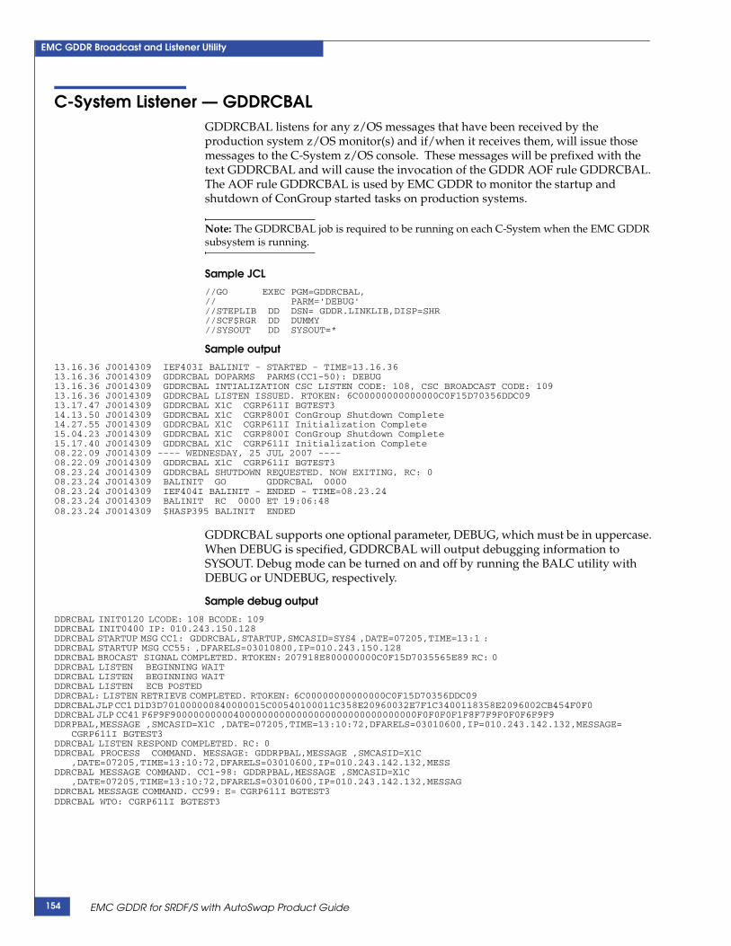
EMC GDDR Broadcast and Listener Utility
C-System Listener — GDDRCBALGDDRCBAL listens for any z/OS messages that have been received by the production system z/OS monitor(s) and if/when it receives them, will issue those messages to the C-System z/OS console. These messages will be prefixed with the text GDDRCBAL and will cause the invocation of the GDDR AOF rule GDDRCBAL. The AOF rule GDDRCBAL is used by EMC GDDR to monitor the startup and shutdown of ConGroup started tasks on production systems.
Note: The GDDRCBAL job is required to be running on each C-System when the EMC GDDR subsystem is running.
Sample JCL//GO EXEC PGM=GDDRCBAL, // PARM='DEBUG' //STEPLIB DD DSN= GDDR.LINKLIB,DISP=SHR //SCF$RGR DD DUMMY //SYSOUT DD SYSOUT=*
Sample output13.16.36 J0014309 IEF403I BALINIT - STARTED - TIME=13.16.36 13.16.36 J0014309 GDDRCBAL DOPARMS PARMS(CC1-50): DEBUG 13.16.36 J0014309 GDDRCBAL INTIALIZATION CSC LISTEN CODE: 108, CSC BROADCAST CODE: 10913.16.36 J0014309 GDDRCBAL LISTEN ISSUED. RTOKEN: 6C00000000000000C0F15D70356DDC0913.17.47 J0014309 GDDRCBAL X1C CGRP611I BGTEST3 14.13.50 J0014309 GDDRCBAL X1C CGRP800I ConGroup Shutdown Complete 14.27.55 J0014309 GDDRCBAL X1C CGRP611I Initialization Complete 15.04.23 J0014309 GDDRCBAL X1C CGRP800I ConGroup Shutdown Complete 15.17.40 J0014309 GDDRCBAL X1C CGRP611I Initialization Complete 08.22.09 J0014309 ---- WEDNESDAY, 25 JUL 2007 ---- 08.22.09 J0014309 GDDRCBAL X1C CGRP611I BGTEST3 08.23.24 J0014309 GDDRCBAL SHUTDOWN REQUESTED. NOW EXITING, RC: 008.23.24 J0014309 BALINIT GO GDDRCBAL 0000 08.23.24 J0014309 IEF404I BALINIT - ENDED - TIME=08.23.24 08.23.24 J0014309 BALINIT RC 0000 ET 19:06:48 08.23.24 J0014309 $HASP395 BALINIT ENDED
GDDRCBAL supports one optional parameter, DEBUG, which must be in uppercase. When DEBUG is specified, GDDRCBAL will output debugging information to SYSOUT. Debug mode can be turned on and off by running the BALC utility with DEBUG or UNDEBUG, respectively.
Sample debug output
DDRCBAL INIT0120 LCODE: 108 BCODE: 109 DDRCBAL INIT0400 IP: 010.243.150.128 DDRCBAL STARTUP MSG CC1: GDDRCBAL,STARTUP,SMCASID=SYS4 ,DATE=07205,TIME=13:1 : DDRCBAL STARTUP MSG CC55: ,DFARELS=03010800,IP=010.243.150.128 DDRCBAL BROCAST SIGNAL COMPLETED. RTOKEN: 207918E800000000C0F15D7035565E89 RC: 0 DDRCBAL LISTEN BEGINNING WAIT DDRCBAL LISTEN BEGINNING WAIT DDRCBAL LISTEN ECB POSTED DDRCBAL: LISTEN RETRIEVE COMPLETED. RTOKEN: 6C00000000000000C0F15D70356DDC09 DDRCBAL JLP CC1 D1D3D701000000840000015C00540100011C358E20960032E7F1C3400118358E2096002CB454F0F0 DDRCBAL JLP CC41 F6F9F9000000000040000000000000000000000000000000F0F0F0F1F8F7F9F0F0F6F9F9 DDRPBAL,MESSAGE ,SMCASID=X1C ,DATE=07205,TIME=13:10:72,DFARELS=03010600,IP=010.243.142.132,MESSAGE=
CGRP611I BGTEST3 DDRCBAL LISTEN RESPOND COMPLETED. RC: 0 DDRCBAL PROCESS COMMAND. MESSAGE: GDDRPBAL,MESSAGE ,SMCASID=X1C
,DATE=07205,TIME=13:10:72,DFARELS=03010600,IP=010.243.142.132,MESS DDRCBAL MESSAGE COMMAND. CC1-98: GDDRPBAL,MESSAGE ,SMCASID=X1C
,DATE=07205,TIME=13:10:72,DFARELS=03010600,IP=010.243.142.132,MESSAG DDRCBAL MESSAGE COMMAND. CC99: E= CGRP611I BGTEST3 DDRCBAL WTO: CGRP611I BGTEST3
EMC GDDR for SRDF/S with AutoSwap Product Guide154

EMC GDDR Broadcast and Listener Utility
BAL command procesor — BALCCommands to GDDRCBAL and GDDRPBAL jobs are issued by executing the batch utility called BALC. The command is specified in the PARM of the EXEC statement in the JCL. The following commands are supported:
◆ SHUTDOWN
Shut down all GDDRPBAL and GDDRCBAL jobs. This is the only way to terminate GDDRPBAL and GDDRCBAL jobs. Keywords 'CSYS' or 'PSYS' can be specified to limit shutdown to GDDRCBAL or GDDRPBAL jobs, respectively.
◆ DEBUG
Turn on debugging for all GDDRPBAL and GDDRCBAL jobs.
◆ UNDEBUG
Turn off debugging for all GDDRPBAL and GDDRCBAL jobs.
◆ UNLISTEN
Initialize BAL CSC ports 108 and 109. “BAL CSC ports” on page 156 provides more information.
The BALC utility can be run on any C-System or production system LPAR.
Command syntax
The following describes the syntax of the PARM value:
[DEBUG,]SHUTDOWN [CSYS/PSYS][DEBUG,]DEBUG[DEBUG,]UNDEBUG[DEBUG,]UNLISTEN RToken
Sample JCL
//GO EXEC PGM=GDDRBALC,PARM='DEBUG,SHUTDOWN PSYS'//STEPLIB DD DSN=GDDR.LINKLIB,DISP=SHR //SCF$RGR DD DUMMY
Sample output
13.15.46 J0014308 IRR010I USERID GDDRUSR IS ASSIGNED TO THIS JOB. 13.15.46 J0014308 ICH70001I GDDRUSR LAST ACCESS AT 13:15:41 ON TUESDAY, JULY 24, 2007 13.15.46 J0014308 $HASP373 BALQUIT STARTED - WLM INIT - SRVCLASS PRDBATHI - SYS SYS4 13.15.46 J0014308 IEF403I BALQUIT - STARTED - TIME=13.15.46 13.15.46 J0014308 GDDRBALC DOPARMS PARMS(CC1-66): DEBUG,SHUTDOWN CSYS 13.15.46 J0014308 GDDRBALC DOPARMS SHUTDOWN CSYS 13.15.47 J0014308 GDDRBALC INIT0200 IP: 010.243.150.128 13.15.47 J0014308 GDDRBALC SHUTDOWN MESSAGE BUILT. MSG: GDDRBALC,SHUTDOWN,SMCASID=SYS4
,DATE=07205,TIME=13:10:72,DF 13.15.47 J0014308 GDDRBALC CSYS BROADCAST COMPLETED. RTOKEN: 207918E800000000C0F15D40FCEE4E49 RC: 0 13.15.47 J0014308 GDDRBALC MAINEXIT RC: 0 13.15.47 J0014308 BALQUIT GO GDDRBALC 0000 8 0 0 13.15.47 J0014308 IEF404I BALQUIT - ENDED - TIME=13.15.47 13.15.47 J0014308 BALQUIT RC 0000 ET 00:00:00 IO 8 CP .0/ .0 13.15.47 J0014308 $HASP395 BALQUIT ENDED
BAL command procesor — BALC 155

EMC GDDR Broadcast and Listener Utility
BAL CSC ports
The SCF cross-system communication capability of EMC ResourcePak Base is based on a numeric port value. For EMC GDDR BAL, the following ports have been registered:
◆ 108
GDDRCBAL jobs listen for new messages from this port. GDDRPBAL jobs send messages to this port.
◆ 109
GDDRPBAL jobs listen for new messages from this port.
CSC RTokensWhen GDDRCBAL or GDDRPBAL begin to listen to a CSC port, an RToken is returned. This RToken must be freed prior to another Listener session with CSC on that LPAR for that port. GDDRCBAL and GDDRPBAL have this functionality built into them for normal and abnormal terminations.
EMC GDDR for SRDF/S with AutoSwap Product Guide156

Index
Aadding a new production system 129adding new RDF groups 132administrator facilities 53Administrator Primary Options menu 53alerts, creating 142#01ALLOC, mainframe installation kit 25allocating global variable backup dataset 41AOF rules 36, 137
suppressing 144#04APPLY, mainframe installation kit 25AUTHCMD 29AUTHPGM 29Automation flag 53Autoswap.Group.Primary parameter 89Autoswap.Group.Secondary parameter 90
Bbacking up global variables 87backup dataset 102BCV volumes, defining 91BCV.siteid.MSC statement 91
CCA-OPS/MVS 36
AOF rules 36, 137changing access rules 36customizing 36merging user applications 39OPSVIEW facilities 82updating CCI parameters 39updating OPSMAIN and OPSOSF 37
CA-OPS/MVS OPSVIEW Primary Options Menu 52CGRP parameter 93#06CLEAN, mainframe installation kit 26community names, specifying for HMC 57completeness
rules 149validation 86
component specifications 147CONCAT.JCLLIB.seq parameter 94CONCAT.SKELS.seq parameter 95
configuring EMC GDDR 41configuring the EMC GDDR HMC interface 47ConGroups_CntlDsn.system-name parameter 96ConGroups_STC_Name.system-name parameter 97consistency
rules 148validation 86
consistency group namechanging 131specifying 93
CONT.system-name parameter 98contingency system, specifying 98C-Systems 121
current master 53ensuring MSF connections 82renaming 128setting up a new system 126specifying security 33specifying the system name 99started procedures 35validating the environment 87
customizing GDDRPROC 41
DDASD, adding 134#02DDDEF, mainframe installation kit 25defining security environment 33device ranges, SRDF/S 114devices, adding to EMC GDDR 134devices, removing 136discover HMC objects 56DYNAPI 92
EECGCLEAN.MSGLEVEL statement 116ECGCLEAN.Task.Number statement 117Edit command 78EMC GDDR Administrator Primary Options menu 42EMC GDDR HMC interface, configuring 47EMC GDDR parameters, loading 42Enterprise Consistency Group, adding a new production
system 129
EMC GDDR for SRDF/S with AutoSwap Product Guide 157

Index
Event.Monitor.Interval statement 118existing C-System, renaming 128
GGDDR.Call_Override parameter 100GDDR.CONFIG parameter 101GDDR.VAR_BACKUP parameter 102GDDRPROC, customizing 41GDDRUX01 141GDDRUX02 141GDDRUX03 142GDDRUX04 142GDDRUX05 142GDDRUX06 143GDDRUX07 144GDDRUXDV 140GDDRUXGV 140GDDRUXSV 140GDDRvrm.XMITFILE 20GDDRvrm.XMITLIB 22global variable backup dataset, allocating 41global variables
backing up 74, 87GDDR.VARS parameter 102loading 87
GNS group, defining 103GNS.siteid.loc.jtype parameter 103
Hhardware requirements 18heartbeat interval value 121Heartbeat.Monitor.Interval parameter 119HFS files, allocating 29HMC 37, 56HMC API DLL, configuring 48HMC interface, configuring 47HMC object discovery 56HMC.siteid parameter 104HMC_Timeout.siteid parameter 120Host Component prefix 58HostComponent_CntlDsn parameter 105
IIKJTSOxx 29installation
mainframe environment requirements 17minimum processor and I/O configuration 18procedure 20software prerequisites 17
installing EMC GDDR started procedures 35IPL.system-name.siteid statement 106ISPF edit 78
JJ0_GK.siteid statement 109JES2 34Job statement options 58
LLNKLST 30Load command 78loading EMC GDDR parameters 42, 77loading parameters 87LPARs, sited.LPAR.system-name parameter 110
Mmainframe environment requirements 17#99MAINT, mainframe installation kit 26Manage HMC option 55, 56, 59, 60, 73, 74master C-System 53merging CA-OPS/MVS user applications 39messages, editing content 142minimum processor and I/O configuration 18minimum software prerequisites 17Missing.Heartbeat.Interval statement 121Missing.Heartbeat.Threshold parameter 122modifying user exits 50MSF connections 82MSFID.csystem-name parameter 111multiple EMC GDDR parameter members, configuring 49
Nnon-LOGR couple datasets, considerations 138
Oonline facilities interface 52OPSMAIN, updating 37OPSOSF, updating 37OPSVIEW facilities 82
Pparameter load processing 46parameter statement processing 85
components 85references and specifications 85validation 86
parameter validation rules 145parameters
Autoswap.Group.Primary 89Autoswap.Group.Secondary 90BCV.siteid.MSC 91CGRP 93CONCAT.JCLLIB.seq 94CONCAT.SKELS.seq 95ConGroups_CntlDsn.system-name 96ConGroups_STC_Name.system-name 97CONT.system-name 98descriptions 88ECGCLEAN.MSGLEVEL 116ECGCLEAN.Task.Number 117Event.Monitor.Interval 118GDDR.Call_Override 100GDDR.CONFIG 101GDDR.VAR_BACKUP 102GNS.siteid.loc.jtype 103Heartbeat.Monitor.Interval 119
EMC GDDR Concepts and Facilities Guide158

Index
HMC.siteid 104HMC_Timeout.siteid 120HostComponet_CntlDsn 105IPL.system-name.siteid 106J0_GK.siteid 109loading 77, 87Missing.Heartbeat.Interval 121Missing.Heartbeat.Threshold 122MSFID.csystem-name 111ResourcePak_STC_Name.c-system-name 112SITE.system-name 113sited.LPAR.system-name 110siteid.C.System.Systemid 99SMF_Record_Type 123sPLX.system-name.type.aorp.siteid 115SRDFS.Devices.siteid 114WTOR_Wait_Interval 124
Primary DASD setting 53Primary Options Menu 53Primary Options menu 42Primary Site setting 53production system, adding 129
RRACF ALTER authority 19RACF functional groups 33RACF profiles and permissions 33RDF groups
adding 132removing 135
#03RECEV, mainframe installation kit 25reference 85removing devices 136removing RDF groups 135removing system or sysplex 137renaming C-Systems 128ResourcePak_STC_Name.c-system-name parameter 112RIMLIB JCL, customizing 22rules
completeness 149consistency 148syntax 146
SSCF suffix 58security environment, defining 33security, defining 33SETSSI command 30setting up a new system 126SITE.system-name parameter 113sited.LPAR.system-name statement 110siteid.C.System.Systemid parameter 99SMF_Record_Type parameter 123software prerequisites 17specification 85Specify GDDR Parameter Dataset panel 77Specify HMC Community Names panel 57sPLX.system-name.type.aorp.siteid statement 115SRDFS.Devices.siteid parameter 114
started procedures, installing 35starting production mainframe workloads 141starting production open-systems workloads 142stopping production mainframe workloads 141stopping production open-systems workloads 142syntax
rules 146validation 86
SYS1.PARMLIB, updating 29sysplex
adding 129removing 137
system parameter file updates 29
UUnplanned scripts 54updating system parameter files 29user exit 7, customizing 37user exit programming considerations 140user exits, modifying 50
Vvalidating the environment 87validation 86
completeness 86consistency 86syntax 86
WWTOR_Wait_Interval parameter 124
EMC GDDR for SRDF/S with AutoSwap Product Guide 159

Index
EMC GDDR Concepts and Facilities Guide160