Embed Size (px)
Citation preview
E M C S H I E L D E DE M C S H I E L D E DEMC ENCLOSURES
Shielded encl.eldon2008.indd 343 12/11/07 16:23:14
344
MASE/MADE
MKSE
MCSE
MKSEMKSEMKDE
MCDE346
348
350
356
E M C S H I E L D E DE M C S H I E L D E DEMC ENCLOSURES
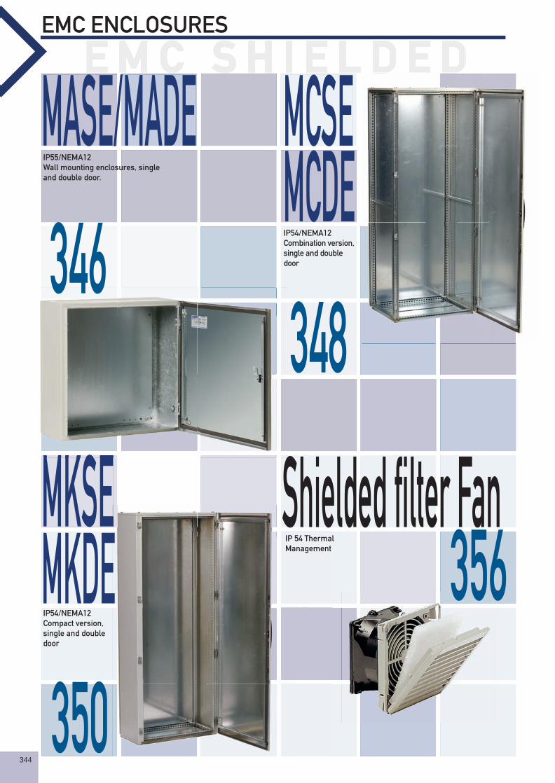
IP55/NEMA12Wall mounting enclosures, single and double door.
IP54/NEMA12Combination version, single and double door
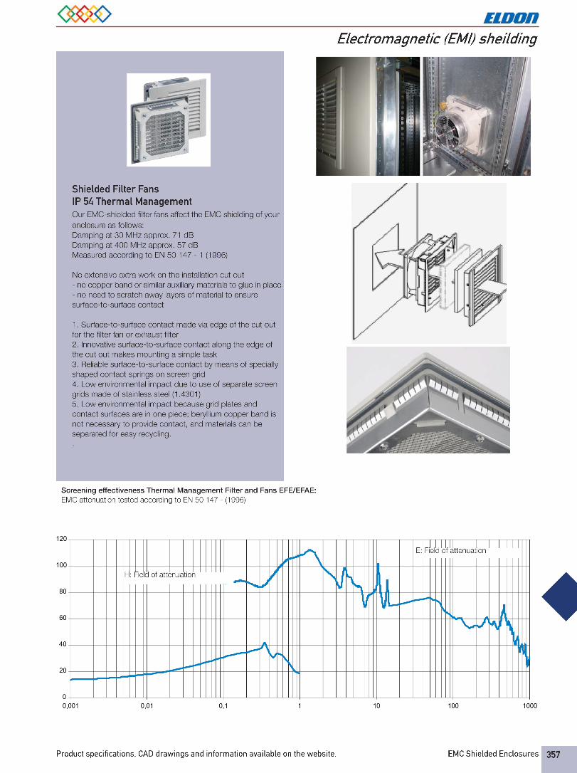
IP 54 ThermalManagement
IP54/NEMA12Compact version, single and double door
Shielded fi lter Fan
Shielded encl.eldon2008.indd 344 12/11/07 16:23:17
345
EMC ENCLOSURES
E M C S H I E L D E DE M C S H I E L D E DE M C S H I E L D E DE M C S H I E L D E DE M C S H I E L D E DE M C S H I E L D E DE M C S H I E L D E DE M C S H I E L D E DE M C S H I E L D E DE M C S H I E L D E DE M C S H I E L D E DE M C S H I E L D E DE M C S H I E L D E DE M C S H I E L D E DE M C S H I E L D E DE M C S H I E L D E DE M C S H I E L D E DE M C S H I E L D E DE M C S H I E L D E DE M C S H I E L D E DE M C S H I E L D E DE M C S H I E L D E DE M C S H I E L D E DE M C S H I E L D E DE M C S H I E L D E DE M C S H I E L D E DE M C S H I E L D E DE M C S H I E L D E DE M C S H I E L D E DE M C S H I E L D E DE M C S H I E L D E DE M C S H I E L D E DE M C S H I E L D E DE M C S H I E L D E DE M C S H I E L D E DE M C S H I E L D E DE M C S H I E L D E DE M C S H I E L D E DE M C S H I E L D E DE M C S H I E L D E DE M C S H I E L D E DE M C S H I E L D E DE M C S H I E L D E DE M C S H I E L D E DE M C S H I E L D E DE M C S H I E L D E DE M C S H I E L D E DE M C S H I E L D E DE M C S H I E L D E DE M C S H I E L D E DE M C S H I E L D E DE M C S H I E L D E DE M C S H I E L D E DE M C S H I E L D E DE M C S H I E L D E DE M C S H I E L D E DE M C S H I E L D E DE M C S H I E L D E DE M C S H I E L D E DE M C S H I E L D E DE M C S H I E L D E DE M C S H I E L D E DE M C S H I E L D E DE M C S H I E L D E DE M C S H I E L D E DE M C S H I E L D E DE M C S H I E L D E DE M C S H I E L D E DE M C S H I E L D E DE M C S H I E L D E DE M C S H I E L D E D
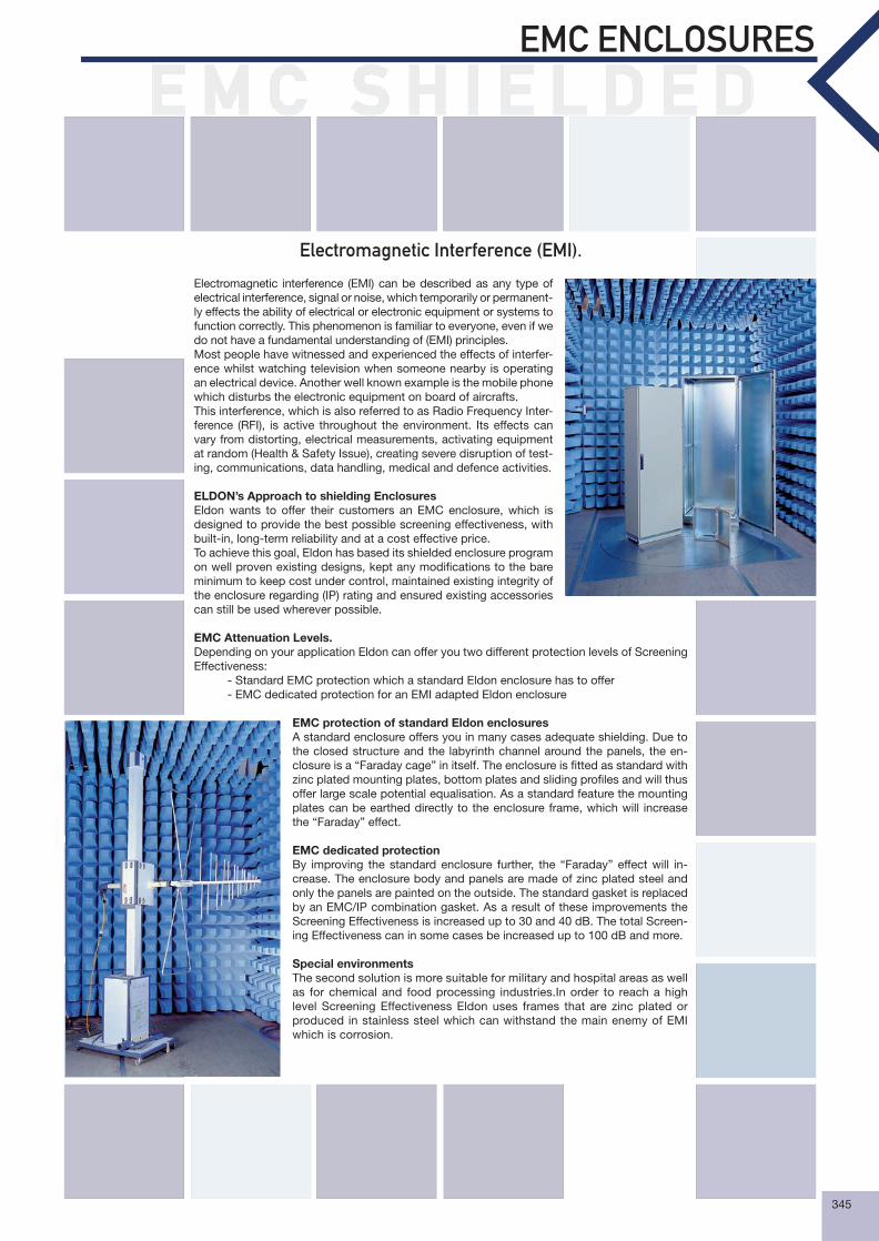
Electromagnetic Interference (EMI).
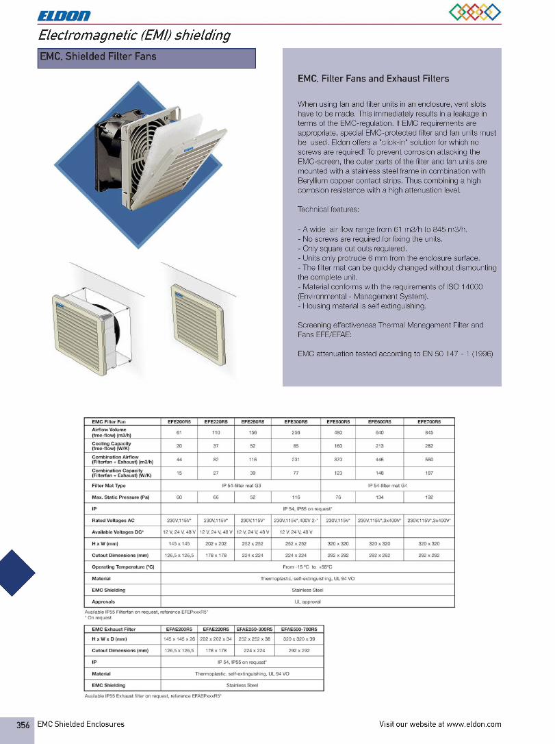
Electromagnetic interference (EMI) can be described as any type of electrical interference, signal or noise, which temporarily or permanent-ly effects the ability of electrical or electronic equipment or systems to function correctly. This phenomenon is familiar to everyone, even if we do not have a fundamental understanding of (EMI) principles.Most people have witnessed and experienced the effects of interfer-ence whilst watching television when someone nearby is operating an electrical device. Another well known example is the mobile phone which disturbs the electronic equipment on board of aircrafts.This interference, which is also referred to as Radio Frequency Inter-ference (RFI), is active throughout the environment. Its effects can vary from distorting, electrical measurements, activating equipment at random (Health & Safety Issue), creating severe disruption of test-ing, communications, data handling, medical and defence activities.
ELDON’s Approach to shielding EnclosuresEldon wants to offer their customers an EMC enclosure, which is designed to provide the best possible screening effectiveness, with built-in, long-term reliability and at a cost effective price.To achieve this goal, Eldon has based its shielded enclosure program on well proven existing designs, kept any modifi cations to the bare minimum to keep cost under control, maintained existing integrity of the enclosure regarding (IP) rating and ensured existing accessories can still be used wherever possible.
EMC Attenuation Levels.Depending on your application Eldon can offer you two different protection levels of Screening Effectiveness:
- Standard EMC protection which a standard Eldon enclosure has to offer- EMC dedicated protection for an EMI adapted Eldon enclosure
EMC protection of standard Eldon enclosuresA standard enclosure offers you in many cases adequate shielding. Due to the closed structure and the labyrinth channel around the panels, the en-closure is a “Faraday cage” in itself. The enclosure is fi tted as standard with zinc plated mounting plates, bottom plates and sliding profi les and will thus offer large scale potential equalisation. As a standard feature the mounting plates can be earthed directly to the enclosure frame, which will increase the “Faraday” effect.
EMC dedicated protectionBy improving the standard enclosure further, the “Faraday” effect will in-crease. The enclosure body and panels are made of zinc plated steel and only the panels are painted on the outside. The standard gasket is replaced by an EMC/IP combination gasket. As a result of these improvements the Screening Effectiveness is increased up to 30 and 40 dB. The total Screen-ing Effectiveness can in some cases be increased up to 100 dB and more.
Special environmentsThe second solution is more suitable for military and hospital areas as well as for chemical and food processing industries.In order to reach a high level Screening Effectiveness Eldon uses frames that are zinc plated or produced in stainless steel which can withstand the main enemy of EMI which is corrosion.
Shielded encl.eldon2008.indd 345 12/11/07 16:23:19
EMC Shielded Enclosures Visit our website at www.eldon.com346
Electromagnetic (EMI) shielding
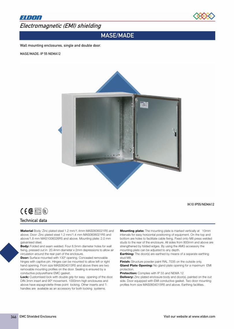
MASE/MADE
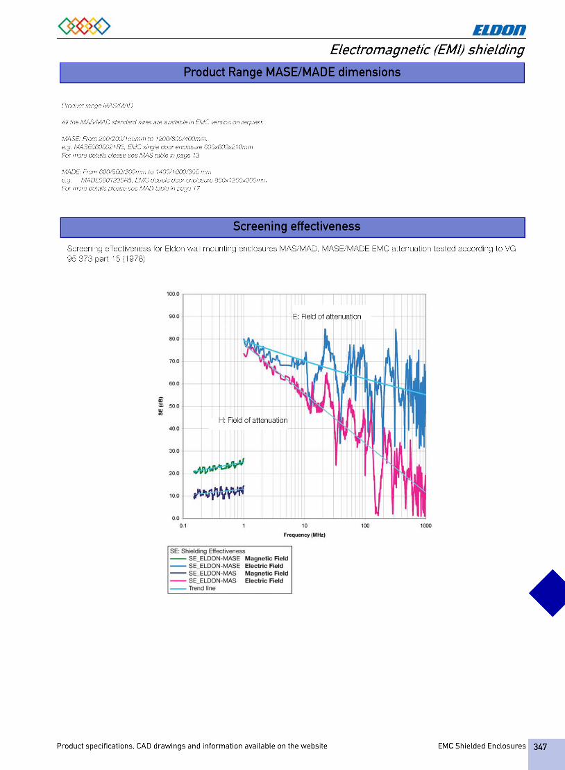
Wall mounting enclosures, single and double door. MASE/MADE: IP 55 NEMA12
IK10 IP55/NEMA12
Technical data
Material Body: Zinc plated steel 1.2 mm/1.4mm MAS0606021R5 and above. Door: Zinc plated steel 1.2 mm/1.4 mm MAS0606021R5 and above/1.8 mm MAS1006026R5 and above. Mounting plate: 2.0 mm galvanised steel.Body: Folded and seam welded. Four 8.5mm diameter holes for wall fixing, pressed out in 20.4mm diameter x 2mm depressions to allow air circulation around the rear part of the enclosure.Door: Surface mounted with 130º opening. Concealed removable hinges with captive pin. Hinges can be mounted to allow left or right hand opening. From size MAS0604015R5 and above there are two removable mounting profiles on the door. Sealing is ensured by a conductive polyurethane EMC gasket.Lock: Customised lock with double grip for easy opening of the door. DIN 3mm insert and 90º movement. 1000mm high enclosures and above have espagnolette three point locking. Other inserts and T-handles are available as an accessory for both locking systems.
Mounting plate: The mounting plate is marked vertically at 10mm intervals for easy horizontal positioning of equipment. On the top and bottom are holes to facilitate cable fixing. Fixed onto M8 press welded studs to the rear of the enclosure. All sides from 800mm and above are strengthened by folded edges. By using the AMG accessory the mounting plate can be adjusted to any depth.Earthing: The door(s) are earthed by means of a separate earthing stud M8.Finish: Structure powder paint RAL 7035 on the outside only.Gland Plate Opening: No gland plate opening for a maximum EMI protection.Protection: Complies with IP 55 and NEMA 12Delivery: Zinc plated enclosure body and door(s), painted on the out side. Door equipped with EMI conductive gasket. Two door mounting profiles from size MAS0604015R5 and above. Earthing facilities.
Chapter_11xEMC_Shielded_Enclosures_R5_2007_45356_0.fm Page 346 Friday, November 16, 2007 4:53 PM
EMC Shielded Enclosures Visit our website at www.eldon.com348
Electromagnetic (EMI) shielding
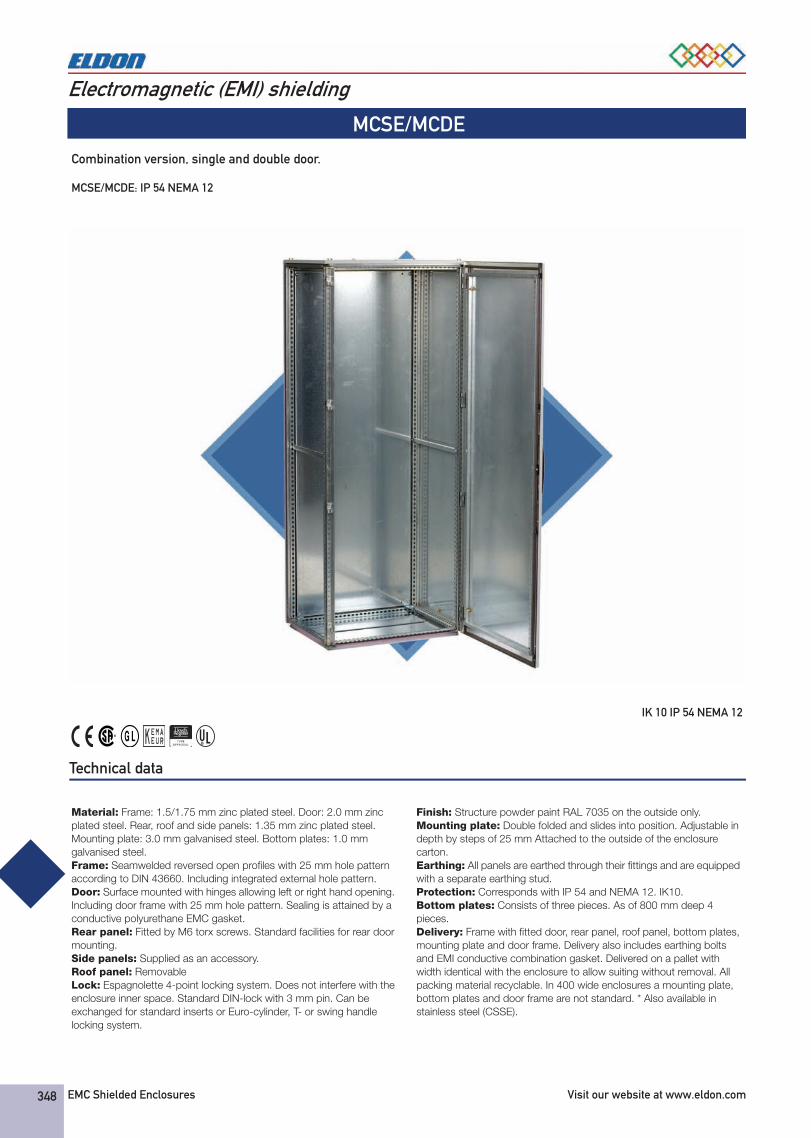
MCSE/MCDE
Combination version, single and double door. MCSE/MCDE: IP 54 NEMA 12
IK 10 IP 54 NEMA 12
Technical data
Material: Frame: 1.5/1.75 mm zinc plated steel. Door: 2.0 mm zinc plated steel. Rear, roof and side panels: 1.35 mm zinc plated steel. Mounting plate: 3.0 mm galvanised steel. Bottom plates: 1.0 mm galvanised steel.Frame: Seamwelded reversed open profiles with 25 mm hole pattern according to DIN 43660. Including integrated external hole pattern.Door: Surface mounted with hinges allowing left or right hand opening. Including door frame with 25 mm hole pattern. Sealing is attained by a conductive polyurethane EMC gasket.Rear panel: Fitted by M6 torx screws. Standard facilities for rear door mounting.Side panels: Supplied as an accessory.Roof panel: RemovableLock: Espagnolette 4-point locking system. Does not interfere with the enclosure inner space. Standard DIN-lock with 3 mm pin. Can be exchanged for standard inserts or Euro-cylinder, T- or swing handle locking system.
Finish: Structure powder paint RAL 7035 on the outside only.Mounting plate: Double folded and slides into position. Adjustable in depth by steps of 25 mm Attached to the outside of the enclosure carton.Earthing: All panels are earthed through their fittings and are equipped with a separate earthing stud.Protection: Corresponds with IP 54 and NEMA 12. IK10.Bottom plates: Consists of three pieces. As of 800 mm deep 4 pieces.Delivery: Frame with fitted door, rear panel, roof panel, bottom plates, mounting plate and door frame. Delivery also includes earthing bolts and EMI conductive combination gasket. Delivered on a pallet with width identical with the enclosure to allow suiting without removal. All packing material recyclable. In 400 wide enclosures a mounting plate, bottom plates and door frame are not standard. * Also available in stainless steel (CSSE).
Chapter_11xEMC_Shielded_Enclosures_R5_2007_45356_0.fm Page 348 Friday, November 16, 2007 4:53 PM
349Product specifications, CAD drawings and information available on the website EMC Shielded Enclosures
Electromagnetic (EMI) shielding
Single Door
Double door
H W D Part No.
2000 600 600 MCSE20066R5800 MCSE20068R5
800 600 MCSE20086R5800 MCSE20088R5
H W D Part No.
2000 800 600 MCDE20086R51000 600 MCDE20106R51200 600 MCDE20126R5
* All enclosures available on request including other dimensions.For EMC sidepanels see SPME.
MCSE/MCDE, IK 10 IP 54 NEMA 12
Screening effectiveness
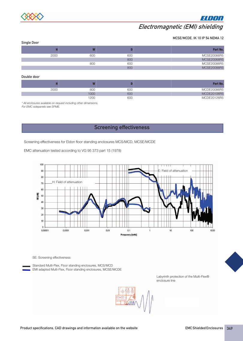
Screening effectiveness for Eldon floor standing enclosures MCS/MCD, MCSE/MCDE
EMC attenuation tested according to VG 95 373 part 15 (1978)
H: Field of attenuation
E: Field of attenuation
SE: Screening effectiveness
Standard Multi-Flex, Floor standing enclosures, MCS/MCD EMI adapted Multi-Flex, Floor standing enclosures, MCSE/MCDE
Labyrinth protection of the Multi-Flex® enclosure line
Chapter_11xEMC_Shielded_Enclosures_R5_2007_45356_0.fm Page 349 Friday, November 16, 2007 4:53 PM
EMC Shielded Enclosures Visit our website at www.eldon.com350
Electromagnetic (EMI) shielding
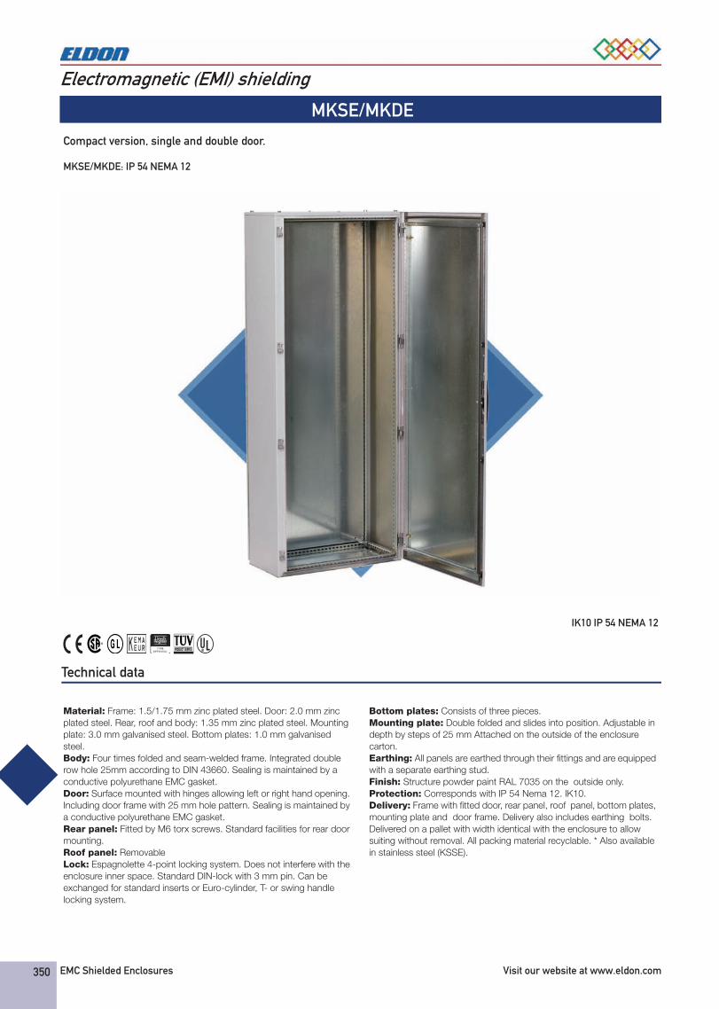
MKSE/MKDE
Compact version, single and double door. MKSE/MKDE: IP 54 NEMA 12
IK10 IP 54 NEMA 12
Technical data
Material: Frame: 1.5/1.75 mm zinc plated steel. Door: 2.0 mm zinc plated steel. Rear, roof and body: 1.35 mm zinc plated steel. Mounting plate: 3.0 mm galvanised steel. Bottom plates: 1.0 mm galvanised steel.Body: Four times folded and seam-welded frame. Integrated double row hole 25mm according to DIN 43660. Sealing is maintained by a conductive polyurethane EMC gasket.Door: Surface mounted with hinges allowing left or right hand opening. Including door frame with 25 mm hole pattern. Sealing is maintained by a conductive polyurethane EMC gasket.Rear panel: Fitted by M6 torx screws. Standard facilities for rear door mounting.Roof panel: RemovableLock: Espagnolette 4-point locking system. Does not interfere with the enclosure inner space. Standard DIN-lock with 3 mm pin. Can be exchanged for standard inserts or Euro-cylinder, T- or swing handle locking system.
Bottom plates: Consists of three pieces.Mounting plate: Double folded and slides into position. Adjustable in depth by steps of 25 mm Attached on the outside of the enclosure carton.Earthing: All panels are earthed through their fittings and are equipped with a separate earthing stud.Finish: Structure powder paint RAL 7035 on the outside only.Protection: Corresponds with IP 54 Nema 12. IK10.Delivery: Frame with fitted door, rear panel, roof panel, bottom plates, mounting plate and door frame. Delivery also includes earthing bolts. Delivered on a pallet with width identical with the enclosure to allow suiting without removal. All packing material recyclable. * Also available in stainless steel (KSSE).
Chapter_11xEMC_Shielded_Enclosures_R5_2007_45356_0.fm Page 350 Friday, November 16, 2007 4:53 PM
351Product specifications, CAD drawings and information available on the website EMC Shielded Enclosures
Electromagnetic (EMI) shielding
Single Door
Double door
H W D Part No.
2000 600 400 MKSE20064R5800 500 MKSE20085R5
H W D Part No.
2000 800 400 MKDE20084R51000 500 MKDE20105R51200 400 MKDE20124R5
* All enclosures available on request including other dimensions.
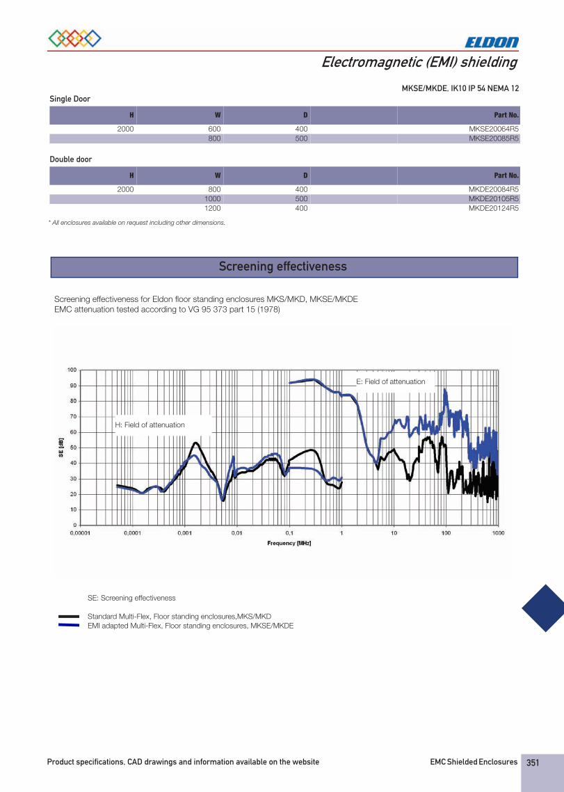
MKSE/MKDE, IK10 IP 54 NEMA 12
Screening effectiveness
Screening effectiveness for Eldon floor standing enclosures MKS/MKD, MKSE/MKDEEMC attenuation tested according to VG 95 373 part 15 (1978)
SE: Screening effectiveness
Standard Multi-Flex, Floor standing enclosures,MKS/MKD EMI adapted Multi-Flex, Floor standing enclosures, MKSE/MKDE
H: Field of attenuation
E: Field of attenuation
Chapter_11xEMC_Shielded_Enclosures_R5_2007_45356_0.fm Page 351 Friday, November 16, 2007 4:53 PM
352 EMC Shielded Enclosures Visit our website at www.eldon.com
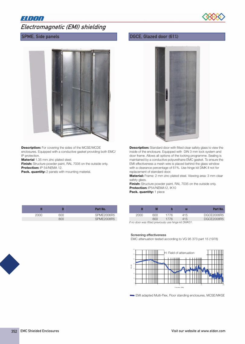
Electromagnetic (EMI) shielding SPME, Side panels
Description: For covering the sides of the MCSE/MCDE enclosures. Equipped with a conductive gasket providing both EMC/IP protection.Material 1.35 mm zinc plated steel.Finish: Structure powder paint, RAL 7035 on the outside only.Protection: IP 54/NEMA 12.Pack. quantity: 2 panels with mounting material.
H D Part No.
2000 600 SPME2006R5800 SPME2008R5
DGCE, Glazed door (61%)
Description: Standard door with fitted clear safety glass to view the inside of the enclosure. Equipped with DIN 3 mm lock system and door frame. Allows all options of the locking programme. Sealing is maintained by a conductive polyurethane EMC gasket. To ensure the EMI effectiveness a mesh wire is placed behind the glass window with a clearance percentage of 61%. Use hinge kit DMK if not for replacement of standard door.Material: Frame: 2 mm zinc plated steel. Viewing area: 3 mm clear safety glass.Finish: Structure powder paint. RAL 7035 on the outside only.Protection: IP54/NEMA12, IK10Pack. quantity: 1 piece
If no door was fitted previously use hinge kit DMK01.
H W h w Part No.
2000 600 1776 415 DGCE2006R5800 1776 415 DGCE2008R5
Screening effectiveness EMC attenuation tested according to VG 95 373 part 15 (1978)
H: Field of attenuation
EMI adapted Multi-Flex, Floor standing enclosures, MCSE/MKSE
Chapter_11xEMC_Shielded_Enclosures_R5_2007_45356_1.fm Page 352 Monday, October 22, 2007 10:54 AM

Product specifications, CAD drawings and information available on the website. EMC Shielded Enclosures 353
Electromagnetic (EMI) shieldingSPD, Separation plates
Description: Separates two bayed enclosures. To be fixed with combining kit CCJ. To achieve IP 43/NEMA1 a neoprene gasket SPDG 01 can be fixed to the panel. For EMI separation the SPDEG gasket must be fitted. Can also be used for partial height/depth separation by choosing a smaller size than the actual enclosure dimensions (however with partial separation the EMI separation is lost).Material: 1.5 mm zinc plated steel.Pack. quantity: 1 piece
H W Part No.
1800 400 SPD1804500 SPD1805
2000 400 SPD2004500 SPD2005600 SPD2006800 SPD2008
2200 600 SPD2206800 SPD2208
Screening effectiveness EMC attenuation tested according to VG 95 373 part 15 (1978)
H: Field of attenuation
Screening effectiveness for Eldon floor standing enclosures separation plate SPD
SPDEG, Gasket for EMC shielding
Description: To obtain an EMC shielded section in a suited panel in combination with the separation plate SPD.Material: Polyurethane foam with conductive layer. (UL94HB)Protection: IP 33/NEMA 1.Pack. quantity: 6 m
Part No.
SPDEG01
CATALOGO 2008.book Page 353 Monday, October 22, 2007 10:12 AM
354 EMC Shielded Enclosures Visit our website at www.eldon.com
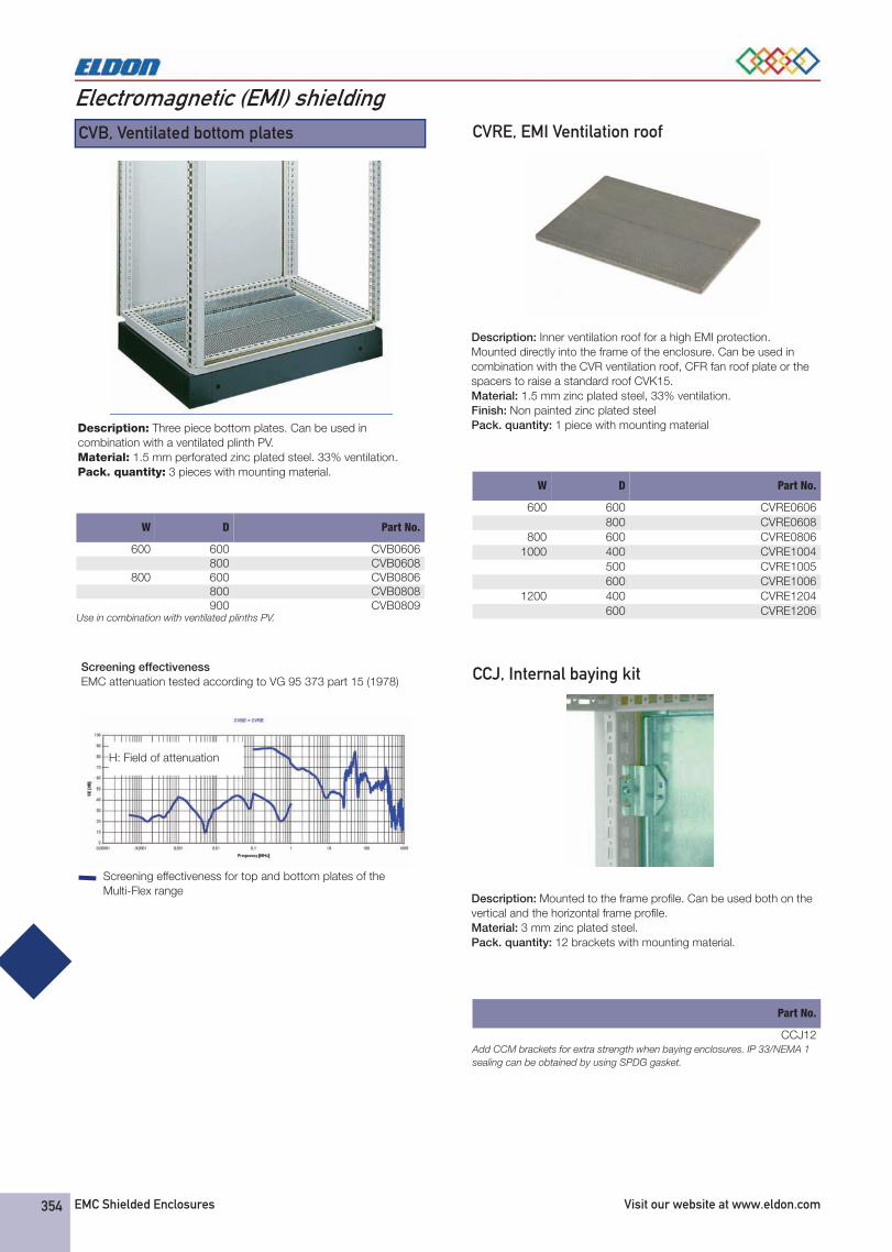
Electromagnetic (EMI) shielding CVB, Ventilated bottom plates
Description: Three piece bottom plates. Can be used in combination with a ventilated plinth PV.Material: 1.5 mm perforated zinc plated steel. 33% ventilation.Pack. quantity: 3 pieces with mounting material.
Use in combination with ventilated plinths PV.
W D Part No.
600 600 CVB0606800 CVB0608
800 600 CVB0806800 CVB0808900 CVB0809
Screening effectiveness EMC attenuation tested according to VG 95 373 part 15 (1978)
Screening effectiveness for top and bottom plates of the Multi-Flex range
H: Field of attenuation
CVRE, EMI Ventilation roof
Description: Inner ventilation roof for a high EMI protection. Mounted directly into the frame of the enclosure. Can be used in combination with the CVR ventilation roof, CFR fan roof plate or the spacers to raise a standard roof CVK15.Material: 1.5 mm zinc plated steel, 33% ventilation.Finish: Non painted zinc plated steelPack. quantity: 1 piece with mounting material
W D Part No.
600 600 CVRE0606800 CVRE0608
800 600 CVRE08061000 400 CVRE1004
500 CVRE1005600 CVRE1006
1200 400 CVRE1204600 CVRE1206
CCJ, Internal baying kit
Description: Mounted to the frame profile. Can be used both on the vertical and the horizontal frame profile.Material: 3 mm zinc plated steel.Pack. quantity: 12 brackets with mounting material.
Add CCM brackets for extra strength when baying enclosures. IP 33/NEMA 1 sealing can be obtained by using SPDG gasket.
Part No.
CCJ12
CATALOGO 2008.book Page 354 Monday, October 22, 2007 10:12 AM
Product specifications, CAD drawings and information available on the website. EMC Shielded Enclosures 355
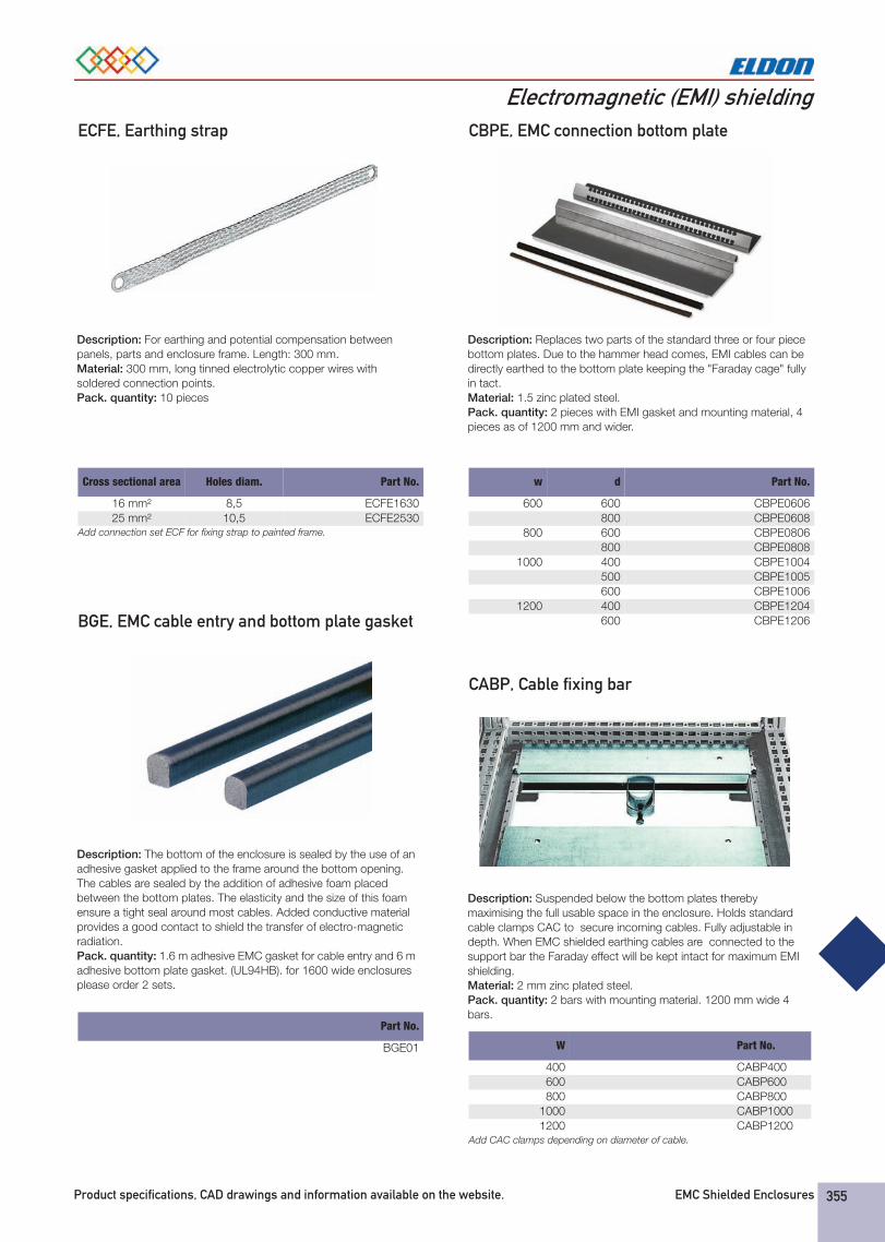
Electromagnetic (EMI) shieldingECFE, Earthing strap
Description: For earthing and potential compensation between panels, parts and enclosure frame. Length: 300 mm.Material: 300 mm, long tinned electrolytic copper wires with soldered connection points.Pack. quantity: 10 pieces
Add connection set ECF for fixing strap to painted frame.
Cross sectional area Holes diam. Part No.
16 mm² 8,5 ECFE163025 mm² 10,5 ECFE2530
BGE, EMC cable entry and bottom plate gasket
Description: The bottom of the enclosure is sealed by the use of an adhesive gasket applied to the frame around the bottom opening. The cables are sealed by the addition of adhesive foam placed between the bottom plates. The elasticity and the size of this foam ensure a tight seal around most cables. Added conductive material provides a good contact to shield the transfer of electro-magnetic radiation.Pack. quantity: 1.6 m adhesive EMC gasket for cable entry and 6 m adhesive bottom plate gasket. (UL94HB). for 1600 wide enclosures please order 2 sets.
Part No.
BGE01
CBPE, EMC connection bottom plate
Description: Replaces two parts of the standard three or four piece bottom plates. Due to the hammer head comes, EMI cables can be directly earthed to the bottom plate keeping the "Faraday cage" fully in tact.Material: 1.5 zinc plated steel.Pack. quantity: 2 pieces with EMI gasket and mounting material, 4 pieces as of 1200 mm and wider.
w d Part No.
600 600 CBPE0606800 CBPE0608
800 600 CBPE0806800 CBPE0808
1000 400 CBPE1004500 CBPE1005600 CBPE1006
1200 400 CBPE1204600 CBPE1206
CABP, Cable fixing bar
Description: Suspended below the bottom plates thereby maximising the full usable space in the enclosure. Holds standard cable clamps CAC to secure incoming cables. Fully adjustable in depth. When EMC shielded earthing cables are connected to the support bar the Faraday effect will be kept intact for maximum EMI shielding.Material: 2 mm zinc plated steel.Pack. quantity: 2 bars with mounting material. 1200 mm wide 4 bars.
Add CAC clamps depending on diameter of cable.
W Part No.
400 CABP400600 CABP600800 CABP800
1000 CABP10001200 CABP1200
CATALOGO 2008.book Page 355 Monday, October 22, 2007 10:12 AM
EMC Shielded Enclosures Visit our website at www.eldon.com358
How to achieve ElectroMagnetic Compatibility (EMC)?1.The mechanism of Electromagnetic Interference (EMI)
The definition of EMC
The council of the European Union defines EMC in Article 4 of their "council directive on the approximation of the laws of the Member States relating to Electromagnetic Compatibility (89/336/EEC)" as property of an "apparatus":- The apparatus shall be so constructed that: the electro-magnetic disturbance it generates does not exceed a level allowing radio and telecommunications equipment and other apparatus to operate as intended" (emission requirement)- The apparatus has an adequate level of intrinsic immunity of electromagnetic disturbance to enable it to operate as intended" [immunity requirement]
This is a very broad definition. The customary route to compliance is the application of standards. There are product standards, applicable to a specific product type (e.g. lighting) and, when not available, there are "generic standards" that can be used. When your product passes all required tests this provides the "presumption of compliance".
What can you do?
The problem is that there is no direct relation between the tests to establish the fact of "EMC" and the measures you can take to conform in that respect. What you need is some basic knowledge on the mechanisms of electromagnetic interference.
Differential and common-mode currents
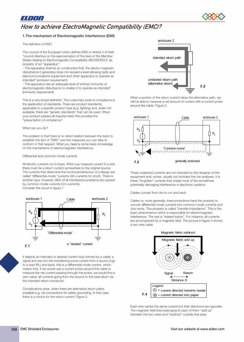
All electric currents run in loops. When you measure current in a wire there must be a return current somewhere to the original source. The currents that determine the functional behaviour of a design are called "differential-mode "currents (dm-currents for short). There is another type, however: 98% of all interference problems are caused by common-mode currents (cm-currents).Consider the circuit in figure 1
It depicts an intended or desired current loop formed by a cable: a signal and are turn line transferring some current from a source (Ug) to a load (RL) and back. this is a differential-mode current, which means that, if we would use a current probe around the cable to measure the net current passing through the probe, we would find a zero value: all currents going from the source to the load return via the intended return conductor.
Complications arise, when there are alternative return paths available e.g. via connections for safety grounding. In that casethere is a choice for the return current: Figure 2.
When a portion of the return current takes the alternative path, we will be able to measure a net amount of current with a current probe around the cable. Figure 3.
These undesired currents are not intended by the designer of the equipment and, worse, usually not included into his analyses. It is these "forgotten" currents that create most of the sometimes potentially damaging interference in electronic systems.
Cables convert from dm to cm and back
Cables or, more generally, interconnections have the property to convert differential mode currents into common-mode currents and vice-versa. This property is called "transfer-impedance". This is the basic phenomenon which is responsible for electromagnetic interference. The rest is "related topics". For instance: all currents are accompanied by a magnetic field. The picture in figure 4 shows a two wire cable.
Each wire carries the same current but their directions are opposite. The magnetic field lines belonging to each of them "add up" between the two wires and "subtract" outside that area.
ENG_Chapter_11xEMC_Shielded_Enclosures_39884_3.fm Page 358 Monday, October 22, 2007 3:21 PM
Product specifications, CAD drawings and information available on the website. EMC Shielded Enclosures 359
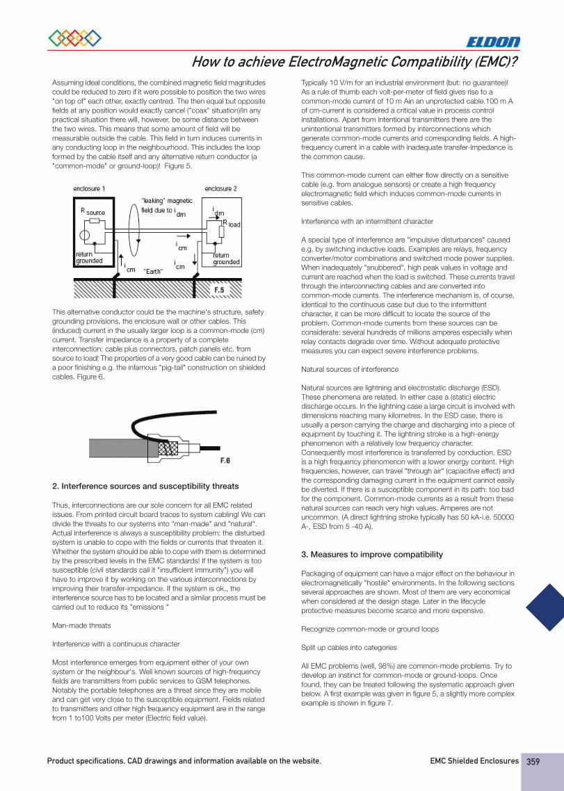
How to achieve ElectroMagnetic Compatibility (EMC)?Assuming ideal conditions, the combined magnetic field magnitudes could be reduced to zero if it were possible to position the two wires "on top of" each other, exactly centred. The then equal but opposite fields at any position would exactly cancel ("coax" situation)!In any practical situation there will, however, be some distance between the two wires. This means that some amount of field will be measurable outside the cable. This field in turn induces currents in any conducting loop in the neighbourhood. This includes the loop formed by the cable itself and any alternative return conductor (a "common-mode" or ground-loop)! Figure 5.
This alternative conductor could be the machine's structure, safety grounding provisions, the enclosure wall or other cables. This (induced) current in the usually larger loop is a common-mode (cm) current. Transfer impedance is a property of a complete interconnection: cable plus connectors, patch panels etc. from source to load! The properties of a very good cable can be ruined by a poor finishing e.g. the infamous "pig-tail" construction on shielded cables. Figure 6.
2. Interference sources and susceptibility threats
Thus, interconnections are our sole concern for all EMC related issues. From printed circuit board traces to system cabling! We can divide the threats to our systems into "man-made" and "natural". Actual interference is always a susceptibility problem: the disturbed system is unable to cope with the fields or currents that threaten it. Whether the system should be able to cope with them is determined by the prescribed levels in the EMC standards! If the system is too susceptible (civil standards call it "insufficient immunity") you will have to improve it by working on the various interconnections by improving their transfer-impedance. If the system is ok., the interference source has to be located and a similar process must be carried out to reduce its "emissions "
Man-made threats
Interference with a continuous character
Most interference emerges from equipment either of your own system or the neighbour's. Well known sources of high-frequency fields are transmitters from public services to GSM telephones. Notably the portable telephones are a threat since they are mobile and can get very close to the susceptible equipment. Fields related to transmitters and other high frequency equipment are in the range from 1 to100 Volts per meter (Electric field value).
Typically 10 V/m for an industrial environment (but: no guarantee)! As a rule of thumb each volt-per-meter of field gives rise to a common-mode current of 10 m Ain an unprotected cable.100 m A of cm-current is considered a critical value in process control installations. Apart from intentional transmitters there are the unintentional transmitters formed by interconnections which generate common-mode currents and corresponding fields. A high-frequency current in a cable with inadequate transfer-impedance is the common cause.
This common-mode current can either flow directly on a sensitive cable (e.g. from analogue sensors) or create a high frequency electromagnetic field which induces common-mode currents in sensitive cables.
Interference with an intermittent character
A special type of interference are "impulsive disturbances" caused e.g. by switching inductive loads. Examples are relays, frequency converter/motor combinations and switched mode power supplies. When inadequately "snubbered", high peak values in voltage and current are reached when the load is switched. These currents travel through the interconnecting cables and are converted into common-mode currents. The interference mechanism is, of course, identical to the continuous case but due to the intermittent character, it can be more difficult to locate the source of the problem. Common-mode currents from these sources can be considerate: several hundreds of millions amperes especially when relay contacts degrade over time. Without adequate protective measures you can expect severe interference problems.
Natural sources of interference
Natural sources are lightning and electrostatic discharge (ESD). These phenomena are related. In either case a (static) electric discharge occurs. In the lightning case a large circuit is involved with dimensions reaching many kilometres. In the ESD case, there is usually a person carrying the charge and discharging into a piece of equipment by touching it. The lightning stroke is a high-energy phenomenon with a relatively low frequency character. Consequently most interference is transferred by conduction. ESD is a high frequency phenomenon with a lower energy content. High frequencies, however, can travel "through air" (capacitive effect) and the corresponding damaging current in the equipment cannot easily be diverted. If there is a susceptible component in its path: too bad for the component. Common-mode currents as a result from these natural sources can reach very high values. Amperes are not uncommon. (A direct lightning stroke typically has 50 kA-i.e. 50000 A-, ESD from 5 -40 A).
3. Measures to improve compatibility
Packaging of equipment can have a major effect on the behaviour in electromagnetically "hostile" environments. In the following sections several approaches are shown. Most of them are very economical when considered at the design stage. Later in the lifecycle protective measures become scarce and more expensive.
Recognize common-mode or ground loops
Split up cables into categories
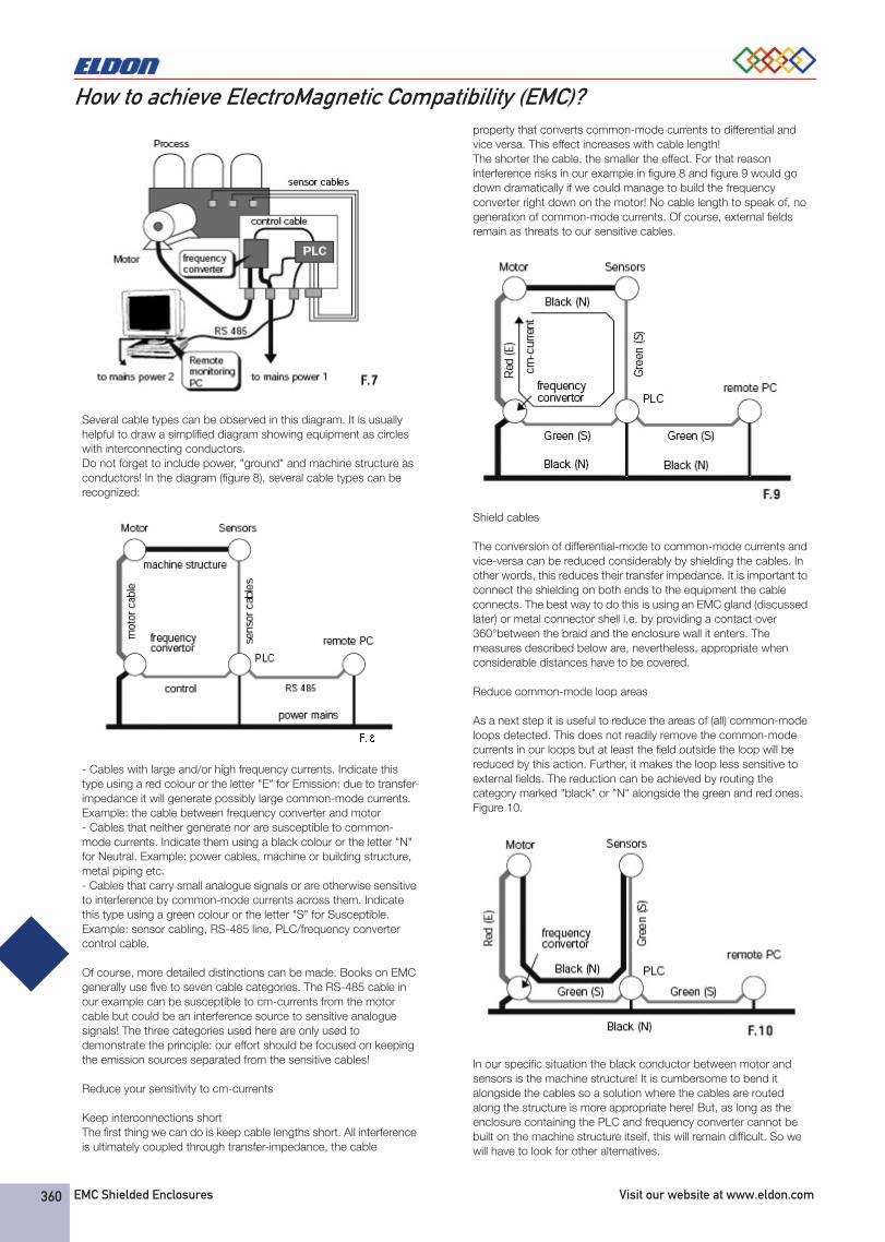
All EMC problems (well, 98%) are common-mode problems. Try to develop an instinct for common-mode or ground-loops. Once found, they can be treated following the systematic approach given below. A first example was given in figure 5, a slightly more complex example is shown in figure 7.
ENG_Chapter_11xEMC_Shielded_Enclosures_39884_3.fm Page 359 Monday, October 22, 2007 3:21 PM
EMC Shielded Enclosures Visit our website at www.eldon.com360
How to achieve ElectroMagnetic Compatibility (EMC)?
Several cable types can be observed in this diagram. It is usually helpful to draw a simplified diagram showing equipment as circles with interconnecting conductors. Do not forget to include power, "ground" and machine structure as conductors! In the diagram (figure 8), several cable types can be recognized:
- Cables with large and/or high frequency currents. Indicate this type using a red colour or the letter "E" for Emission: due to transfer-impedance it will generate possibly large common-mode currents. Example: the cable between frequency converter and motor- Cables that neither generate nor are susceptible to common-mode currents. Indicate them using a black colour or the letter "N" for Neutral. Example: power cables, machine or building structure, metal piping etc.- Cables that carry small analogue signals or are otherwise sensitive to interference by common-mode currents across them. Indicate this type using a green colour or the letter "S" for Susceptible. Example: sensor cabling, RS-485 line, PLC/frequency converter control cable.
Of course, more detailed distinctions can be made. Books on EMC generally use five to seven cable categories. The RS-485 cable in our example can be susceptible to cm-currents from the motor cable but could be an interference source to sensitive analogue signals! The three categories used here are only used to demonstrate the principle: our effort should be focused on keeping the emission sources separated from the sensitive cables!
Reduce your sensitivity to cm-currents
Keep interconnections short The first thing we can do is keep cable lengths short. All interference is ultimately coupled through transfer-impedance, the cable
property that converts common-mode currents to differential and vice versa. This effect increases with cable length! The shorter the cable, the smaller the effect. For that reason interference risks in our example in figure 8 and figure 9 would go down dramatically if we could manage to build the frequency converter right down on the motor! No cable length to speak of, no generation of common-mode currents. Of course, external fields remain as threats to our sensitive cables.
Shield cables
The conversion of differential-mode to common-mode currents and vice-versa can be reduced considerably by shielding the cables. In other words, this reduces their transfer impedance. It is important to connect the shielding on both ends to the equipment the cable connects. The best way to do this is using an EMC gland (discussed later) or metal connector shell i.e. by providing a contact over 360°between the braid and the enclosure wall it enters. The measures described below are, nevertheless, appropriate when considerable distances have to be covered.
Reduce common-mode loop areas
As a next step it is useful to reduce the areas of (all) common-mode loops detected. This does not readily remove the common-mode currents in our loops but at least the field outside the loop will be reduced by this action. Further, it makes the loop less sensitive to external fields. The reduction can be achieved by routing the category marked "black" or "N" alongside the green and red ones. Figure 10.
In our specific situation the black conductor between motor and sensors is the machine structure! It is cumbersome to bend it alongside the cables so a solution where the cables are routed along the structure is more appropriate here! But, as long as the enclosure containing the PLC and frequency converter cannot be built on the machine structure itself, this will remain difficult. So we will have to look for other alternatives.
ENG_Chapter_11xEMC_Shielded_Enclosures_39884_3.fm Page 360 Monday, October 22, 2007 3:21 PM
Product specifications, CAD drawings and information available on the website. EMC Shielded Enclosures 361
How to achieve ElectroMagnetic Compatibility (EMC)?EMC grounding: "current boundaries"
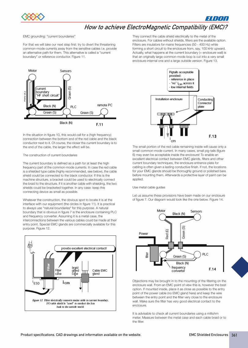
For that we will take our next step first: try to divert the threatening common-mode currents away from the sensitive cables i.e. provide an alternative path for them. This alternative is called a "current boundary" or reference conductor. Figure 11.
In the situation in figure 10, this would call for a (high frequency) connection between the bottom end of the red cable and the black conductor next to it. Of course, the closer the current boundary is to the end of the cable, the larger the effect will be.
The construction of current boundaries
The current boundary is defined as a path for at least the high frequency part of the common-mode currents. In case the red cable is a shielded type cable (highly recommended, see below), the cable shield could be connected to the black conductor. If this is the machine structure, a bracket could be used to electrically connect the braid to the structure. If it is another cable with shielding, the two shields could be bracketed together. In any case: keep this connecting device as small as possible.
Whatever the construction, the obvious spot to locate it is at the interface with our equipment (the circles in figure 11). It is practical to always use "natural boundaries" for this purpose. A natural boundary that is obvious in figure 7 is the enclosure containing PLC and frequency converter. Assuming it is a metal case, the interconnections between the various cables could be made at their entry point. Special EMC glands are commercially available for this purpose. Figure 12.
They connect the cable shield electrically to the metal of the enclosure. For cables without shields, filters are the available option. Filters are insulators for mains frequencies (50 - 400 Hz) while forming a short circuit to the enclosure from, say, 100 kHz upward. Actually, what happens at the current boundary (= enclosure wall) is that an originally large common-mode loop is cut into a very small enclosure-internal one and a large outside version. Figure 13.
The small portion of the red cable remaining inside will cause only a small common-mode current. In many cases, small pig-tails (figure 6) may even be acceptable inside the enclosure! To enable an excellent electrical contact between EMC glands, filters and other current boundary techniques, the enclosure entrance plate for cabling is often given a lasting conductive finish. If not, the locations for your EMC glands should be thoroughly ground or polished bare before mounting them. Afterwards a protective layer of paint can be applied.
Use metal cable guides
Let us assume these provisions have been made on our enclosure of figure 7. Our diagram would look like the one below. Figure 14.
Objections may be brought in to the mounting of the filtering on the enclosure wall. From an EMC point of view this is, however the best option. If mounted inside, place it as close as possible to the entry point of the power cable (no EMC gland here) and keep the wire between the entry point and the filter very close to the enclosure wall. Make sure the filter has very good electrical contact to the enclosure.
It is advisable to check all current boundaries using a milliohm meter. Measure between the metal case and each cable braid or to the filter.
ENG_Chapter_11xEMC_Shielded_Enclosures_39884_3.fm Page 361 Monday, October 22, 2007 3:21 PM
EMC Shielded Enclosures Visit our website at www.eldon.com362
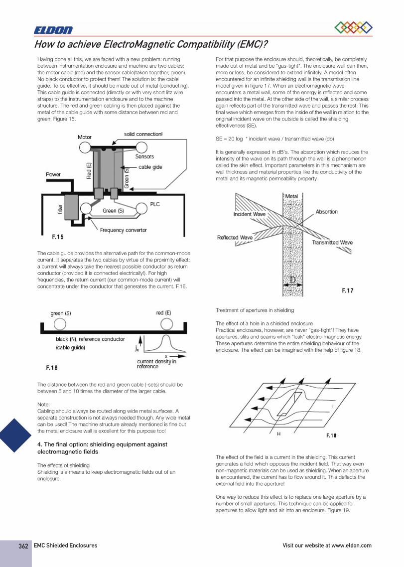
How to achieve ElectroMagnetic Compatibility (EMC)?Having done all this, we are faced with a new problem: running between instrumentation enclosure and machine are two cables: the motor cable (red) and the sensor cable(taken together, green). No black conductor to protect them! The solution is: the cable guide. To be effective, it should be made out of metal (conducting). This cable guide is connected (directly or with very short litz wire straps) to the instrumentation enclosure and to the machine structure. The red and green cabling is then placed against the metal of the cable guide with some distance between red and green. Figure 15.
The cable guide provides the alternative path for the common-mode current. It separates the two cables by virtue of the proximity effect: a current will always take the nearest possible conductor as return conductor (provided it is connected electrically!). For high frequencies, the return current (our common-mode current) will concentrate under the conductor that generates the current. F.16.
The distance between the red and green cable (-sets) should be between 5 and 10 times the diameter of the larger cable.
Note: Cabling should always be routed along wide metal surfaces. A separate construction is not always needed though. Any wide metal can be used! The machine structure already mentioned is fine but the metal enclosure wall is excellent for this purpose too!
4. The final option: shielding equipment against electromagnetic fields
The effects of shieldingShielding is a means to keep electromagnetic fields out of an enclosure.
For that purpose the enclosure should, theoretically, be completely made out of metal and be "gas-tight". The enclosure wall can then, more or less, be considered to extend infinitely. A model often encountered for an infinite shielding wall is the transmission line model given in figure 17. When an electromagnetic wave encounters a metal wall, some of the energy is reflected and some passed into the metal. At the other side of the wall, a similar process again reflects part of the transmitted wave and passes the rest. This final wave which emerges from the inside of the wall in relation to the original incident wave on the outside is called the shielding effectiveness (SE).
SE = 20 log * incident wave / transmitted wave (db)
It is generally expressed in dB's. The absorption which reduces the intensity of the wave on its path through the wall is a phenomenon called the skin effect. Important parameters in this mechanism are wall thickness and material properties like the conductivity of the metal and its magnetic permeability property.
Treatment of apertures in shielding
The effect of a hole in a shielded enclosurePractical enclosures, however, are never "gas-tight"! They have apertures, slits and seams which "leak" electro-magnetic energy. These apertures determine the entire shielding behaviour of the enclosure. The effect can be imagined with the help of figure 18.
The effect of the field is a current in the shielding. This current generates a field which opposes the incident field. That way even non-magnetic materials can be used as shielding. When an aperture is encountered, the current has to flow around it. This deflects the external field into the aperture!
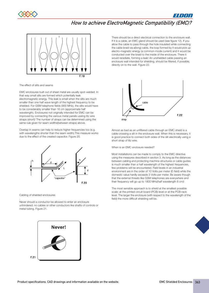
One way to reduce this effect is to replace one large aperture by a number of small apertures. This technique can be applied for apertures to allow light and air into an enclosure. Figure 19.
ENG_Chapter_11xEMC_Shielded_Enclosures_39884_3.fm Page 362 Monday, October 22, 2007 3:21 PM
Product specifications, CAD drawings and information available on the website. EMC Shielded Enclosures 363
How to achieve ElectroMagnetic Compatibility (EMC)?
The effect of slits and seams
EMC enclosures built out of sheet metal are usually spot-welded. In that way small slits are formed which potentially leak electromagnetic energy. This leak is small when the slits are much smaller than one half wave length of the highest frequency to be shielded. For GSM telephone fields (900 MHz), the slits would have to be considerably smaller than 16 cm (approximate half wavelength). Enclosures not originally intended for EMC can be improved by connecting the various metal panels ussing litz wire straps (short)! The number of straps can be determined using the same rule given for seam widths(between straps) above.
Overlap in seams can help to reduce higher frequencies too (e.g. with wavelengths shorter than the seam width).This measure works due to the effect of the created capacitor. Figure 20.
Cabling of shielded enclosures.Never should a conductor be allowed to enter an enclosure unhindered: no cables or other conductors like shafts of controls or metal tubing. Figure 21.
There should be a direct electrical connection to the enclosure wall. If it is a cable, an EMC gland should be used (see figure 12). If you allow the cable to pass through the hole insulated while connecting the cable braid via a(long) cable, the loop formed by it would pick up electro-magnetic energy (a common-mode current) and it would be conducted over the braid to the inside of the enclosure. There it would reradiate, forming a leak! An unshielded cable passing an enclosure wall intended for shielding, should be filtered, if possible, directly on to the wall. Figure 22.
Almost as bad as an unfiltered cable through an EMC shield is a cable crossing a slit in the enclosure wall. When this is necessary, it is good practice to connect both sides of the slit electrically using a short strap of litz wire.
When is an EMC enclosure needed?
Most installations can be made to comply to the EMC directive using the measures described in section 3. As long as the distances between cabling and protecting machine-structures or cable guides is much smaller than a half wavelength of the highest frequencies, few problems will be encountered. Field levels in an industrial environment are in the order of 10 Volts per meter (E-field) while the domestic value hardly exceeds 3 Volts per meter. Be aware though that the external threats like GSM telephones are everywhere and their frequency will go up to 1800 MHz(half wavelength 8 cm)!
The most sensible approach is to shield at the smallest possible scale: at the printed circuit board (PCB) level or at the PCB-rack level. The larger the enclosure (with respect to the wavelength of the field) the more difficult shielding will be.
ENG_Chapter_11xEMC_Shielded_Enclosures_39884_3.fm Page 363 Monday, October 22, 2007 3:21 PM