Embed Size (px)
Citation preview

Hardware Overview
EMC Data Domain DD2200 and DD2500 Systems
Hardware Overview300-119-009 REV. 05
May, 2014
This document describes the hardware components of DD2200 and DD2500 systems.
u Related Documentation..............................................................................................2u System Features.........................................................................................................3u Storage Capacity........................................................................................................ 4u Front Panel.................................................................................................................5u Back Panel.................................................................................................................6u Slot Assignments....................................................................................................... 9u Internal System Components................................................................................... 10

Related Documentation
Note
Hard copies of a document may be out of date. Always check for the current version of adocument on the EMC Support website at https://support.emc.com.
There are various types of documents available that are related to the use of Data Domainproducts:
u End user documents, for example, user guides, hardware installation guides,administrator guides, software guides, part replacement guides, release notes andothers.
u Integration documents about how to integrate Data Domain systems with third partybackup applications.
u Compatibility matrices that show which components are compatible with each other.
Viewing EMC Data Domain DocumentsProcedure
1. Connect to the EMC Support website at https://support.emc.com.
2. If you are a registered user, log in and skip to the next step. Otherwise:
a. Click Register Here.
b. Follow the online registration steps, filling in all required fields.
c. After your registration is processed, you will receive an email confirmation.
3. Click the Support by Product option.
4. Enter a product name in Find a Product, for example, DD990. Click the search icon atthe right of this field.
5. On the next screen, click Documentation.
6. At the right, all documents are displayed that fit the criteria. A menu at the left isautomatically populated with various categories of these documents, for example,Manual and Guides.
7. Store a search by clicking Add to my favorites.
8. When you revisit the Support by Product page, your most recent searches aredisplayed at the bottom of the screen.
Your suggestions help us continue to improve the accuracy, organization, and overallquality of the user publications. Please send your opinions of any document to [email protected].
Hardware Overview
2 EMC Data Domain DD2200 and DD2500 Systems Hardware Overview

System FeaturesThe table summarizes the DD2200 and DD2500 system features.
Feature DD2500 DD2200
Rack Height 2U, supported in four-post racks only
NVRAM Module One 2-GB NVRAM-BBU combinationmodule for data integrity during apower outage. Not hot-swappable.
System memory-BBU module-harddisk drive combination for dataintegrity during a power outage.
BBU Module BBU module is combined with theNVRAM module.
One BBU module for data integrityduring a power outage. Not hot-swappable.
Power 1 +1 redundant, hot-swappable power units
Fans Seven fan assemblies. Not hot-swappable.
Drives (SAS only) 7 or 12 3-TB HDD hot-swappabledrives.
7 or 12 2-TB HDD hot-swappabledrives.
I/O Module Slots Four replaceable I/O module (FC,Ethernet, and SAS) slots.Not hot-swappable.
Two replaceable I/O module (FC andEthernet) slots.Not hot-swappable.
Memory l 4 x 8 GB DIMM installedsupports 1 x 30-TB SAS shelfadding up to 30 TB of externalraw capacity
l 8 x 8 GB DIMM installedsupports up to 4 x 30-TB SASshelves or 3 x 45-TB SASshelves adding up to 135 TB ofexternal raw capacity
l Base configuration contains 2 x 4GB DIMM
l Extended configuration contains4 x 4 GB DIMM (required for a 12disk drive system)
Processors One 8-core processor One 6-core processor
Rack Mounting Rack mount kit included with each system. Adjustable between 18 - 36 in.(45.7 - 76.2 cm).
Hardware Overview
System Features 3

Storage CapacityThe table lists the capacities of the DD2200 and DD2500 systems. EMC Data Domainsystem internal indexes and other product components use variable amounts of storage,depending on the type of data and the sizes of files. If you send different data sets tootherwise identical systems, one system may, over time, have room for more or lessactual backup data than another.
Note
EMC Data Domain system commands compute and display amounts of disk space or dataas decimal multiples of certain powers of two (210, 220, 230, and so forth). For example, 7GiB of disk space = 7 x 230 bytes = 7 x 1,073,741,824 bytes. EMC Data Domain refers tothis process as Base 2 calculation.
Table 1 DD2200 and DD2500 storage capacity
System/InstalledMemory
InternalDisks
RawStorage(Base10)
Data StorageSpace(Base 2Calculation)
Data StorageSpace(Base 10Calculation)
External Storage
DD22002 x 4 GBDIMM
Seven 3.5in. 2 TBSAS HDDs
7 drives: 7012GiB
7 drives: 7531GB
NA
DD22004 x 4 GBDIMM
Seven ortwelve 3.5in. 2 TBSAS HDDs
7 drives: 7012GiB7+5 drives:12356 GiB
12 drives: 16100GiB
7 drives: 7531GB7+5 drives:13270 GB
12 drives:17291 GB
NA
DD25004 x 8 GBDIMM
Seven ortwelve 3.5in. 3 TBSAS HDDs
21 TB or36 TB
7 drives: 10671GiB7+5 drives:18763 GiB
12 drives: 24334GiB
7 drives:11458 GB7+5 drives:20147 GB
12 drives:26129 GB
1 x 30-TB SAS shelf;up to 30 TB of rawcapacity.
DD25008 x 8 GBDIMM
Seven ortwelve 3.5in. 3 TBSAS HDDs
21 TB or36 TB
7 drives: 10671GiB7+5 drives:18763 GiB
12 drives: 24334GiB
7 drives:11458 GB7+5 drives:20147 GB
12 drives:26129 GB
Up to a maximum of 4x 30-TB SAS shelvesor 3 x 45-TB SASshelves; up to 135 TBof raw capacity.
Note
For information about Data Domain expansion shelves, see the separate document, EMCData Domain Expansion Shelf Hardware Guide.
Hardware Overview
4 EMC Data Domain DD2200 and DD2500 Systems Hardware Overview

Front PanelFigure 1 Front panel components
Disk DrivesA system contains up to 12 hot-swappable 3.5" HDD SAS disk drives located in the frontof the chassis. Left to right, drives are numbered 0-3 in the top row, 4-7 in the middlerow, and 8-11 in the bottom row.
u The base configuration contains 7 disk drives in locations 0 through 6. Drive bays7-11 contain bay blanks.
u The expanded configuration contains 12 disk drives.
Front LED IndicatorsThe front of the system contains 12 disk drive status LEDs that are normally blue andblink when there is activity on the disk. The LEDs are shaped like triangles, and the apexof the triangle points either left or right toward the disk whose status it represents. If thedisk drive has a failure, the disk’s status LED turns from blue to amber.
There are two square-shaped system LEDs. A blue system power LED is on whenever thesystem has power. An amber system fault LED is normally off and is lit amber wheneverthe chassis or any other FRU in the system requires service.
Figure 2 Disk and system LEDs
Part State
System fault Normally unlit. Amber indicates fault.
System power Steady blue indicates normal power.
Disk drive status Steady blue or blinking blue indicates normal operation. Amberindicates fault or failure.
When the bezel is affixed, the blue system power LED can be seen through the bezel.
Hardware Overview
Front Panel 5

Figure 3 Bezel showing lighted system power LED
Back PanelThe figures show hardware features on the back of a system.
Figure 4 Features on rear of DD2500 chassis
(1) I/O module in slot 0
(2) NVRAM-BBU combination module in slot 4
(3) Power supply number 0
Figure 5 Features on rear of DD2200 chassis
(1) I/O module in slot 0
(2) Blank filler
(3) Power supply number 0
(4) BBU module
Power Supply UnitsA system has two power supply units, numbered 0 and 1 from left to right. Each powerunit has LEDs (shown in the photo) that indicates the following states:
Hardware Overview
6 EMC Data Domain DD2200 and DD2500 Systems Hardware Overview

u AC LED (top): Glows green when AC input is good
u DC LED (middle): Glows green when DC output is good
u Symbol “!” (lower): Glows solid amber for fault or attention
Figure 6 Power supply unit LEDs
Onboard Interfaces, SN Pull-Out Tag and LEDsThe onboard interfaces are located on the far lower left side when facing the back of thesystem. The onboard interfaces enable you to check system status and connect to thesystem through a serial console or through Ethernet connections.
A USB port is provided for use during service of the system to allow booting from a USBflash device.
Figure 7 Onboard interfaces and SN tag for the DD2500 system
(1) LEDs: top is SP power LED and the bottom is SP service LED
(2) Dual-port 10G BaseT
l Top port: physical #4, logical ethMe
l Bottom port: physical #5, logical ethMf
(3) Service network port
(4) USB port
(5) Serial port
(6) Quad-port 1 Gigabit Ethernet
Hardware Overview
Onboard Interfaces, SN Pull-Out Tag and LEDs 7
l Top left port: physical #2, logical ethMc
l Top right port: physical #0, logical ethMa
l Lower left port: physical #3, logical ethMd
l Lower right port: physical #1, logical ethMb
(7) I/O module LED
(8) Serial number pull-out tag
Figure 8 Onboard interfaces and SN tag for the DD2200 system
(1) LEDs: top is SP power LED and the bottom is SP service LED
(2) Quad-port Gigabit Ethernet
l Top left port: physical #2, logical ethMc
l Top right port: physical #0, logical ethMa
l Lower left port: physical #3, logical ethMd
l Lower right port: physical #1, logical ethMb
(3) Service network port
(4) USB port
(5) Serial port
(6) I/O module LED
(7) Serial number pull-out tag
Figure 9 Serial number pull-out tag for both systems
Hardware Overview
8 EMC Data Domain DD2200 and DD2500 Systems Hardware Overview

Rear LED Status Summary
Part State
SP service Blue indicates normal operation. Amber indicates fault.
SP power Steady green indicates normal power. Dark indicates no power.
I/O module Steady green indicates normal operation. Amber indicates fault orfailure.
Power supply AC Glows green when AC input is good
Power supply DC Glows green when DC output is good
Power supply symbol “!” Glows solid amber for fault or attention
Slot AssignmentsThe table shows the I/O module slot assignments for a system. See the figures in BackPanel on page 6 for a view of the slot positions on the back panel and Figure 10 on page10 for a top view.
Table 2 DD2200 and DD2500 slot assignments
Slot Number DD2200 DD2500
0 FC, Ethernet or empty FC, Ethernet or empty
1 FC, Ethernet or empty FC, Ethernet or empty
2 Not available FC, Ethernet or empty
3 Not available SAS or empty
4 Not available NVRAM-BBU
When a system is upgraded, the newly inserted I/O module should go into the nextavailable slot position. The following slot loading guidelines apply:
u For mixed populations, populate all Ethernet I/O modules first, then populate the FCI/O modules.
u For Ethernet I/O modules, populate the leftmost (slot 0) slot first, if empty, then slot 1and so on.
u Slot 3 is reserved for SAS I/O modules (DD2500 system only).
FC I/O Module OptionAn FC I/O module is a dual-port Fibre Channel module. The optional virtual tape library(VTL) feature requires at least one FC I/O module. Three FC I/O module slots for theDD2500 and two FC I/O module slots for the DD2200 are available to be used.
Ethernet I/O Module OptionsThree Ethernet I/O module slots for the DD2500 and two Ethernet I/O module slots for theDD2200 are available to be used. The available Ethernet I/O modules are:
Hardware Overview
Slot Assignments 9
u Dual Port 10GBase-SR Optical with LC connectors
u Dual Port 10GBase-CX1 Direct Attach Copper with SPF+ module
u Quad Port 1000Base-T Copper with RJ-45 connectors
u Quad port 2 port 1000Base-T Copper (RJ45) /2 port 1000Base-SR Optical
u Quad port 10GBase-T Copper
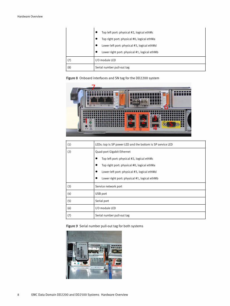
Internal System ComponentsThe photo shows the system with the storage processor (SP) module removed from thechassis. The top of the photo shows the rear of the system.
Figure 10 Top view of SP module (DD2500 system shown)
Cooling FansA storage processor module contains seven cooling fans. The fans provide cooling for theprocessor, DIMMs, and I/O modules. A system can run with one fan module faulted. Fromthe front of the system, fans are numbered 1, 3, 4, 5, and 6 in the first row and 0 and 2 inthe second row (right to left). The bottom of the photo shows the front of the system.
Hardware Overview
10 EMC Data Domain DD2200 and DD2500 Systems Hardware Overview

Figure 11 Top view of SP module with air duct removed (DD2200 system shown)
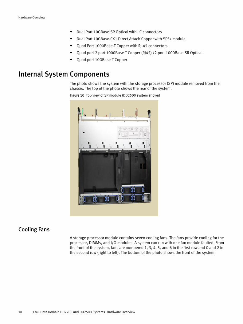
DIMM ModulesA DD2500 system contains either 4 x 8 GB or 8 x 8 GB memory DIMMs. The base systemDIMMs are located in slots labeled CHAD0, CHBD0, CHCD0 and CHDD0. An expandedsystem contains a DIMM in each slot.
A DD2200 system contains either 2 x 4 GB or 4 x 4 GB memory DIMMs. The base systemDIMMs are located in slots labeled CHAD0 and CHBD0. An expanded system contains aDIMM in slots labeled CHAD0, CHBD0, CHCD0 and CHDD0.
The bottom of the photo is the front of the system. The left group of 4 DIMM slots from leftto right are labeled CHBD1, CHBD0, CHAD1, and CHAD0. The right group of 4 DIMM slotsare labeled CHDD1, CHDD0, CHCD1, and CHCD0. A photo of the DD2200 DIMM locationsis seen in Cooling Fans on page 10.
Hardware Overview
DIMM Modules 11
Figure 12 DIMM location (DD2500 system shown)
Hardware Overview
12 EMC Data Domain DD2200 and DD2500 Systems Hardware Overview
Copyright © 2014 EMC Corporation. All rights reserved. Published in USA.
Published May, 2014
EMC believes the information in this publication is accurate as of its publication date. The information is subject to change withoutnotice.
The information in this publication is provided as is. EMC Corporation makes no representations or warranties of any kind withrespect to the information in this publication, and specifically disclaims implied warranties of merchantability or fitness for aparticular purpose. Use, copying, and distribution of any EMC software described in this publication requires an applicable softwarelicense.
EMC², EMC, and the EMC logo are registered trademarks or trademarks of EMC Corporation in the United States and other countries.All other trademarks used herein are the property of their respective owners.
For the most up-to-date regulatory document for your product line, go to EMC Online Support (https://support.emc.com).
Hardware Overview
DIMM Modules 13