Embed Size (px)
Citation preview

Hyun D. Kim and John D. SaundersGlenn Research Center, Cleveland, Ohio
Embedded Wing Propulsion Conceptual Study
NASA/TM—2003-212696
November 2003
https://ntrs.nasa.gov/search.jsp?R=20030112863 2020-03-23T00:03:08+00:00Z

The NASA STI Program Office . . . in Profile
Since its founding, NASA has been dedicated tothe advancement of aeronautics and spacescience. The NASA Scientific and TechnicalInformation (STI) Program Office plays a key partin helping NASA maintain this important role.
The NASA STI Program Office is operated byLangley Research Center, the Lead Center forNASA’s scientific and technical information. TheNASA STI Program Office provides access to theNASA STI Database, the largest collection ofaeronautical and space science STI in the world.The Program Office is also NASA’s institutionalmechanism for disseminating the results of itsresearch and development activities. These resultsare published by NASA in the NASA STI ReportSeries, which includes the following report types:
∑ TECHNICAL PUBLICATION. Reports ofcompleted research or a major significantphase of research that present the results ofNASA programs and include extensive dataor theoretical analysis. Includes compilationsof significant scientific and technical data andinformation deemed to be of continuingreference value. NASA’s counterpart of peer-reviewed formal professional papers buthas less stringent limitations on manuscriptlength and extent of graphic presentations.
∑ TECHNICAL MEMORANDUM. Scientificand technical findings that are preliminary orof specialized interest, e.g., quick releasereports, working papers, and bibliographiesthat contain minimal annotation. Does notcontain extensive analysis.
∑ CONTRACTOR REPORT. Scientific andtechnical findings by NASA-sponsoredcontractors and grantees.
∑ CONFERENCE PUBLICATION. Collectedpapers from scientific and technicalconferences, symposia, seminars, or othermeetings sponsored or cosponsored byNASA.
∑ SPECIAL PUBLICATION. Scientific,technical, or historical information fromNASA programs, projects, and missions,often concerned with subjects havingsubstantial public interest.
∑ TECHNICAL TRANSLATION. English-language translations of foreign scientificand technical material pertinent to NASA’smission.
Specialized services that complement the STIProgram Office’s diverse offerings includecreating custom thesauri, building customizeddatabases, organizing and publishing researchresults . . . even providing videos.
For more information about the NASA STIProgram Office, see the following:
∑ Access the NASA STI Program Home Pageat http://www.sti.nasa.gov
∑ E-mail your question via the Internet [email protected]
∑ Fax your question to the NASA AccessHelp Desk at 301–621–0134
∑ Telephone the NASA Access Help Desk at301–621–0390
∑ Write to: NASA Access Help Desk NASA Center for AeroSpace Information 7121 Standard Drive Hanover, MD 21076

Hyun D. Kim and John D. SaundersGlenn Research Center, Cleveland, Ohio
Embedded Wing Propulsion Conceptual Study
NASA/TM—2003-212696
November 2003
National Aeronautics andSpace Administration
Glenn Research Center
Prepared for theVehicle Propulsion Integration Symposiumsponsored by the NATO Research and Technology AgencyWarsaw, Poland, October 6–9, 2003

Acknowledgments
The authors would like to express their thanks to Danny P. Hwang, Daniel N. Kosareo, James R. Davic,and Jeffrey J. Berton, NASA Glenn Research Center and Mark Waters, Georgia Institute of Technology,
for their contributions to this paper.
Available from
NASA Center for Aerospace Information7121 Standard DriveHanover, MD 21076
National Technical Information Service5285 Port Royal RoadSpringfield, VA 22100
Trade names or manufacturers’ names are used in this report foridentification only. This usage does not constitute an officialendorsement, either expressed or implied, by the National
Aeronautics and Space Administration.
Available electronically at http://gltrs.grc.nasa.gov
The Propulsion and Power Program atNASA Glenn Research Center sponsored this work.

NASA/TM�2003-212696 1
Embedded Wing Propulsion Conceptual Study
Hyun D. Kim* and John D. Saunders** National Aeronautics and Space Administration
Glenn Research Center Cleveland, Ohio 44135
ABSTRACT As a part of distributed propulsion work under NASA�s Revolutionary Aeropropulsion Concepts or RAC project, a new propulsion-airframe integrated vehicle concept called Embedded Wing Propulsion (EWP) is developed and examined through system and computational fluid dynamics (CFD) studies. The idea behind the concept is to fully integrate a propulsion system within a wing structure so that the aircraft takes full benefits of coupling of wing aerodynamics and the propulsion thrust stream. The objective of this study is to assess the feasibility of the EWP concept applied to large transport aircraft such as the Blended-Wing-Body aircraft. In this paper, some of early analysis and current status of the study are presented. In addition, other current activities of distributed propulsion under the RAC project are briefly discussed.
NOMENCLATURE
Fj jet force M Mach number Mj tail-jet Mach number at nozzle exit plane M∞ free-stream Mach number U axial velocity U∞ free-stream axial velocity c airfoil chord cd sectional drag coefficient cl sectional lift coefficient cp pressure coefficient α angle-of-attack θ jet flap angle
BACKGROUND
NASA has been investigating distributed propulsion concepts applied to future aircraft under the Revolutionary Aeropropulsion Concepts or RAC project. The project is primarily directed towards the NASA Aerospace Technology Enterprise Goal �Pioneer Technology Innovation� and also supported by the �Revolutionize Aviation� and �Advance Space Transportation� goals. This paper will address some of the current activity in the area of distributed propulsion under the RAC project looking 20 to 40 years into the future.
Since the introduction of large jet powered transport aircraft such as the Boeing 707, the majority of these vehicles have been designed by placing thrust-generating engines either under the wings or on the fuselage to minimize aerodynamic interactions on the vehicle operation. The exception to this kind of configuration was the British De Havilland Comet aircraft, which was one of the first generation jet transports. Figure 1 shows some early aircrafts with various propulsion system placements. This aircraft had
* Aerospace Engineer, Airbreathing Systems Analysis Office ** Aerospace Engineer, Turbomachinery and Propulsion Systems Division

NASA/TM�2003-212696 2
all its engines buried in the thick wing root section but really never took advantage of the full benefits of integrating two distinct systems, i.e., the propulsion system and wing. The Comet suffered initially mysterious but now well documented structural fatigue failures of the fuselage that dramatically affected the production. Beyond the fatigue failures, the embedded propulsion system caused maintenance problems because of low reliability of the first generation jet engines of the 1950�s. The apparently low drag configuration also caused adverse aerodynamic interactions between engine flow / wing aerodynamics. In spite of these setbacks, a modern version of the Comet continues to fly reconnaissance missions as the BAe Nimrod.
In the late 1960�s, a turbofan propulsive wing Vertical/Short Take-off and Landing or V/STOL
concept ADAM III1 was studied for various missions but the design never went into production possibly due to the problem of ducting hot gas through the wing structure. For this concept, the gas generators and their inlets were installed near the wing root to provide hot gas to the turbines that drove high bypass ratio turbofans. The turbofans and turbines were located in the wing away from the gas generators. The hot gases from the gas generators were routed through long ducts across the wing span to the location where the turbines were installed. The inlets and nozzles for the turbofans and turbines were also all within the wing structure away from the gas generators and provided distributed thrust to the vehicle. Aside from the conventional cylindrical fuselage type vehicles, there were flying wing aircrafts such as the Northrop YB-49 and more recent B-2 bomber for the military that had all the engines buried in the wing. In particular, the YB-49, which was flown in the 1940�s, had four linearly arranged engines in each side of wing with subsonic rectangular inlets and conventional circular nozzles at each side of the wing leading edges and trailing edges, respectively. See Fig. 1. In 1977, a new flying wing concept was patented and provided additional innovations to the current EWP concept.2 This design had inlets and nozzles at the wing leading and trailing edges and buried engines in the wing, providing a completely distributed thrust for the vehicle from the wing tip to tip.
OBJECTIVES
Today�s modern materials, aircraft control techniques, and computational aerodynamic and structural design may enable the promise of embedded wing propulsion to be more fully realized. The concept of Embedded Wing Propulsion or EWP is to install many propulsive engines within a wing structure so that it maximizes vehicle benefits by coupling propulsion and wing aerodynamics. In this concept, all propulsion related components such as inlets, engines and nozzles are located within the wing structure so that the coupled aerodynamic advantage between wing and propulsion system can be maximized. This may now be possible with the rapid advancement of engine designs with high performance and reliability, in addition to advances in CFD technology that will enable engineers to optimize such a concept for a very efficient vehicle. From the beginning of this concept formulation, the followings have been identified as possible benefits:
• Reduction in aircraft drag and weight by eliminating engine nacelles. • Reduction in aircraft drag through wing wake fill-in with engine thrust stream. • Reduction in fuel consumption by ingesting thick boundary layer flow. • High lift via high aspect ratio vectored thrust wing trailing edge nozzles providing powered lift,
boundary layer control and/or supercirculation around the wing enabling short take-off capability. • Jet flap capability using spanwide vectored thrust stream during short take-off and landing. • Reduction in aircraft noise. • Improvement in safety through a redundant propulsion system. • Reduction in aircraft weight through inlet/nozzle/wing structure integration. • Elimination of aircraft control surfaces through differential and vectoring thrust for pitch, roll, and
yaw moments.

NASA/TM�2003-212696 3
• Easy engine replacement provided that engines are small and lighter. • Application of non-traditional engine concepts such as the multi-fan engine or constant volume
engine that may be more applicable to the EWP concept. The constant volume engine will be ideal for supersonic aircraft where the wing needs to be thin compared to subsonic aircraft.
However, because of its inherent characteristics of integrating the propulsion system within the wing structure, the followings are identified as possible disadvantages:
• Increased internal flow drag. • On board engine maintenance difficulty due to the embedded engine installation. • Engine blade burst into airframe.
Additionally, there are several items that were considered in the past to be disadvantages due to their complexity but that may now have solutions because of modern design and analysis techniques:
• Fuel storage and distribution to many engines. • Aerodynamic/propulsive design optimization. • Aerodynamic/propulsive coupling causing control complexity. • Structural design complexity. • Multidimensional noise propagation. • Integrated engine cycles for low specific fuel consumption. • Inlet/nozzle design for extreme shape change.
The objectives for the current study are to analyze some of the above areas using a NASA�s 800
passenger BWB design as a baseline and to provide guidance to future generation aircraft design using distributed propulsion. In this paper, some of early analysis and the current status of the study are presented.
EMBEDDED WING PROPULSION CONCEPT To demonstrate the feasibility of the EWP concept, a 800 passenger Blended-Wing-Body (BWB) transport aircraft was chosen as the baseline model and studied by repositioning and distributing its propulsion system along the wingspan. From the beginning of this study, engine sizing was an issue and it was decided that a moderately small size engine such as the General Electric�s CF34 with low specific fuel consumption was more ideal for the large BWB with EWP. Table 1 shows the number of required engines based on the 800 passenger BWB study by Liebeck.3 In addition, it was determined that modification of the original BWB payload volume structure was to be avoided so that there is minimal impact on overall vehicle structure. These two requirements then led to two versions of an EWP design as shown in Fig. 2 and 3. Fig. 2 shows configuration A with engines all buried inside the wing between the payload volume and the outer wing. This configuration has inlets and nozzles near the wing leading edge and trailing edge respectively, and provides direct powered lift using thrust-vectoring nozzles. Fig. 3 shows configuration B with engines all integrated within the BWB�s wing trailing edge. For this configuration, higher propulsive efficiency may be achieved by ingesting all or a large amount of upper wing surface boundary layer flow. Ref. 4 describes the benefits of ingesting wakes or boundary layer flows on propulsive efficiency. However, because the inlets ingest thick boundary layer flow generated by the upper surface of the wing, the pressure recovery and flow distortion at the engine fan face plane may be compromised. In addition, powered lift for configuration B would be difficult to achieve due to the nozzle location being near the vehicle trailing edge and away from the vehicle center of gravity, causing large pitching moment. In order to assess the benefits of thrust vectoring near the wing trailing edge, simple 2-dimensional computational fluid dynamics (CFD) simulations were performed using a NACA0012 airfoil, truncating the last 15% of airfoil chord and replacing it with a thrust vectoring jet flow or jet flap. Fig. 4 shows the geometry. For this initial study, an inlet is not included in the geometry for simplicity and due to an as yet

NASA/TM�2003-212696 4
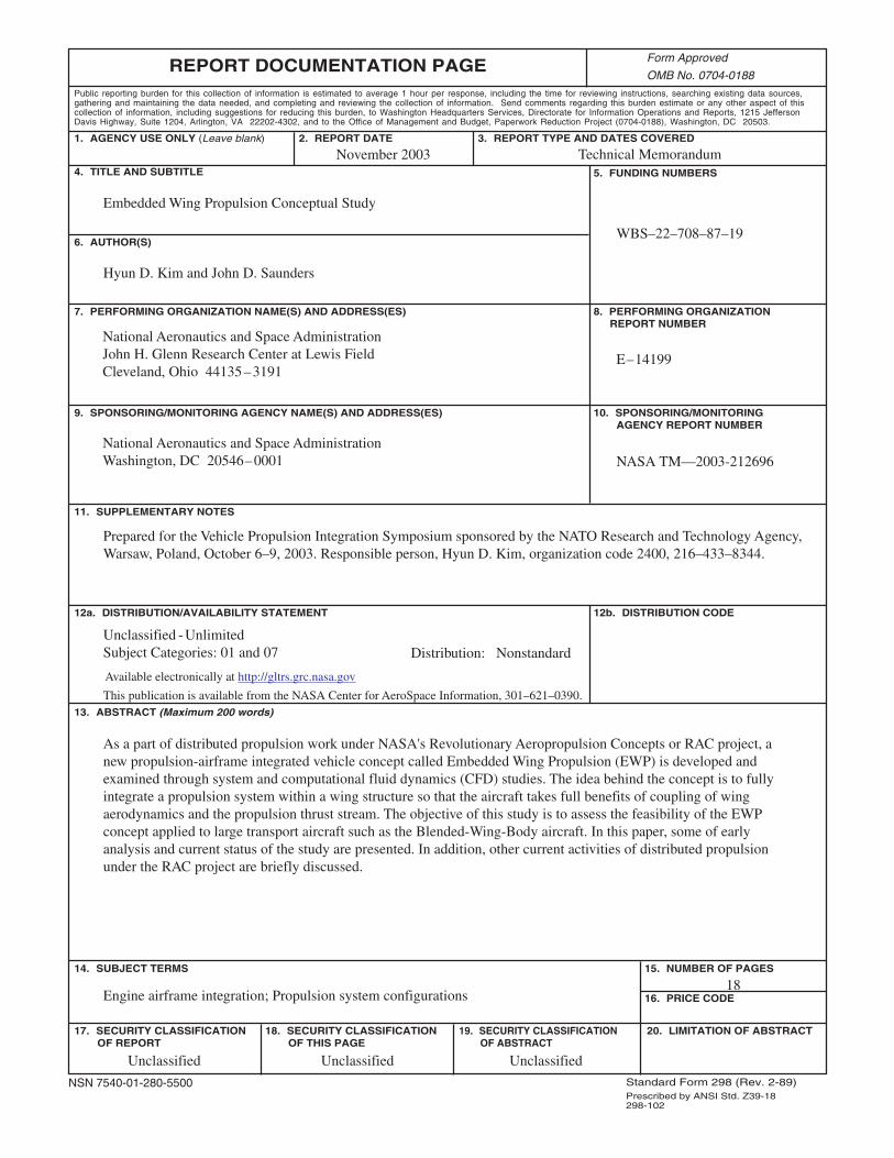
undefined inlet configuration. In addition, the intent of this study was primarily to demonstrate the effect of the airfoil trailing edge thrust vectoring jet on airfoil pressure distribution, lift and drag. For the simulation, a general purpose Navier-Stokes CFD code (WIND)5 was used and a turbulent (Spalart-Allmaras one-equation) model was implemented. Table 2 shows the computational boundary conditions in the free stream and at the jet nozzle exit plane. Figure 5 shows the effect of the jet at the end of modified airfoil on lift and drag coefficients. The lift and drag coefficients are based on free stream conditions and the original untruncated NACA0012 airfoil chord length. They are calculated by integrating only the upper and lower airfoil surface pressure distributions without including the vectored jet force contribution to the lift. In addition, the momentum or ram drag of the airflow in the jet is not incorporated into the force accounting. The study was performed at the low speed condition of M∞=0.2 with Mj=0.95 while varying angle-of-attack, α, and jet angle, θ. Positive θ implies that the jet flow is leaving downward from the airfoil trailing edge nozzle, providing both powered lift and thrust at the same time. At a fixed θ=30o and various positive α�s, the lift coefficients are all positive and increase as α increases, proving that the trailing edge jets provide extra circulation around airfoil as if there is a flap near the trailing edge. Also, the drag coefficients are very low and, in fact, for α lower than 12o, they are negative suggesting that there is forward thrust, i.e., a large airfoil leading edge suction force, rather than a net drag on the airfoil. However, it is noted that, because the jet is at a vectored angle, there is a loss in net axial jet force that corresponds to Fj(1-cos(θ)) which must be accounted for during overall vehicle force calculations. Also, a similar study was performed at fixed α=0o and various θ�s to see the effect on lift and drag of increasing jet flap angle. As the jet angle is deflected more downward, i.e. larger jet angle, the lift coefficients are increased and drag coefficients are decreased, suggesting that the supercirculation caused by jet flap is providing higher lift and forward thrust. Again, the forward thrust is generated by the large suction force near the wing leading edge. Finally, Fig. 6 and 7 show Mach number contours and surface pressure distributions of the jet flap airfoil at the various angles-of-attack and jet angles, showing how the flow changes around the airfoil in the presence of the jet flap.
OTHER DISTRIBUTED PROPULSION CONCEPTS UNDER NASA�S RAC PROJECT
In addition to the subsonic transport application of the EWP concept, two other propulsion/airframe integration concepts are being considered for these initial system level studies: a supersonic transport and a cross flow fan. Supersonic distributed propulsion concept For supersonic transport vehicle design, the Georgia Institute of Technology (Georgia Tech) is leading a system analysis effort on the business jet and 300 passenger sized vehicle concepts. A traditional supersonic aircraft typically incorporates podded propulsion designed for the supersonic environment but conceptually similar to a subsonic aircraft. The isolated propulsion system pods cause vehicle penalties that this vehicle study at Georgia Tech will help to quantify. For supersonic flight, an added drag term results from the shock waves surrounding the vehicle. Depending on the vehicle configuration, this �wave drag� may constitute from 10 to 50% of the overall vehicle drag. In addition to the wave drag, the shock waves will coalesce to varying degrees to cause a sonic boom at the ground. A significant contribution to the boom signature is cause by the propulsion pods. By carefully integrating the propulsion pods into the wing structure, a novel configuration that will reduce wave drag and thus have greater overall mission efficiency might be possible. Such a notional vehicle concept is shown in Fig. 8. For this vehicle concept, two conceptual propulsion systems are being considered. For a short-term development cycle, traditional gas turbine engines will be evaluated. On a longer time horizon, a novel propulsion system, utilizing distributed power and perhaps electric fuel cell power, is beginning to be investigated. To produce the required lift, additional swept wing panels outboard of the engine nacelle panels may be required.
In terms of supersonic wing design, the delta planform is a compromise between subsonic and
supersonic aerodynamics. The low lift curve slope causes low wing loading and compromised supersonic

NASA/TM�2003-212696 5
cruise performance. Georgia Institute of Technology�s Advanced System Design Laboratory has developed and continually updates a system level approach to vehicle/mission design. The tools that are being developed will be coupled to propulsion system sizing / low and high speed aerodynamics / sonic boom prediction and elements of structural design to create a fully integrated aircraft design. An optimal vehicle design will be synthesized and evaluated. Final comparisons will be made to the evolved High Speed Civil Transport (HSCT) developed during NASA High Speed Research (HSR) program. Cross flow fan concept For low speed application, the concept of a cross flow fan or transverse fan has been proposed and investigated for many years. The fan is a 2-dimensional spanwide propulsor that are integrated within a wing structure to distribute the thrust along the wingspan. Fig. 9 shows one such configuration where the fan ingests the air from the wing upper and lower surfaces and ejects the air toward the wing trailing edge.6 In this configuration, two gas generators mounted at the wing-root and the wing-tip transmit the power to the transverse fan rotors that are placed near the wing trailing edge and connected by flex-couplings or universal joints. However, due to low performance of the fan and difficulty of installation within an aircraft wing structure, the concept was never put into practice. Under the NASA�s RAC project, there are currently two separate efforts by the United States Naval Post-Graduate School and Syracuse University to improve the performance of the fan by using advanced experimental and CFD techniques and to analyze the concept at a vehicle systems level. It is hoped that, at the end of these two studies, a high performance cross flow fan may be realized and applied to future air vehicles with short take-off and landing, and efficient cruise capabilities.
CONCLUSION
The current status and some early analyses of the Embedded Wing Propulsion (EWP) concept being
investigated under NASA�s Revolutionary Aeropropulsion Concepts or RAC project are presented. The idea behind the concept is to fully integrate or embed a propulsive system within a wing structure to maximize vehicle benefits by coupling propulsion and wing aerodynamics. In a way, the concept is to emulate nature by taking a cue from birds. Similar to birds, the EWP concept provides adaptable thrust without any propulsive devices exposed outside the airframe and with very high performance and safety for all flight.
To study the feasibility of such concept, an 800 passenger Blended-Wing-Body (BWB) vehicle was
chosen as a baseline configuration and was modified with the EWP concept. Even for this very large aircraft, a number of moderately small size engines with low specific fuel consumption rate was chosen because of physical constraints. For the initial study, two vehicle configurations were proposed. The design for one configuration is to completely bury the engines inside the wing between the wing leading edge inlets and trailing edge nozzles. The other design has the engines installed near the wing trailing edge so that the engines ingest large amount of boundary layer flow for high propulsive efficiency.
In order to assess the benefits of thrust vectoring near the wing trailing edge, a simple 2-dimensional
computational fluid dynamics (CFD) study was performed using a modified airfoil with jet flap. The study showed large lift coefficients and unusually negative drag coefficients at various flow conditions. These enhanced aerodynamics are caused by the trailing nozzle jet performing like virtual flap by providing strong suction force at the airfoil leading edge.
Based on the initial conceptual study and the possible benefits that are proposed, the concept appears
to be adaptable to a wide range of missions with very efficient performance from take-off to landing. The EWP concept does require high efficiency, suitably sized engines and systems that can be incorporated within a wing structure. In addition, if the propulsive engines are completely integrated with wing airframe, as if the airframe is a part of the engine or the engine is a part of the airframe, greater benefits might be realized. The EWP concept provides a nontraditional configuration to incorporate modern design tools and technologies with intent to significantly reduce air transport costs, enable new missions and enhance safety.

NASA/TM�2003-212696 6
REFERENCES
1. Winborn, B.R. Jr,., �The ADAM III V/STOL Concept,� AIAA 69-201, February 1969. 2. Grow, Harlow, �Aircraft Wing with Internal Flow control Propulsion,� United States Patent
#4,026,500, 1977. 3. Liebeck, R., �Design of the Blended-Wing-Body Subsonic Transport,� AIAA 2002-0002,
January 2002 4. Smith, L.H. Jr., �Wake Ingestion Propulsion Benefit,� Journal of Propulsion and Power, Vol. 9,
No. 1, Jan-Feb. 1993. 5. Towne, C., The WIND Code Version 5.0, http://www.grc.nasa.gov/www/winddocs/index.html,
Last modified April 29, 2003. 6. Hancock, J.P., �Test of a High Efficiency Transverse Fan,� AIAA-80-1243, June 1980.
Table 1. Conventional engine selection comparison for 800 passenger BWB with Embedded Wing Propulsion concept.
Free stream Tail-jet at nozzle exit plane Mach No. 0.2 0.95
Total pressure (psia) 14.7 22.15 Total temperature (oR) 520 520
Table 2. Flow conditions for NACA 0012 airfoil jet flap CFD study.
EnginesGeneral Electric
GE-90General Electric
CF34Williams International
FJ22Length (inches) 193 129 41
Weight (lb) 16700 2400 80Thrust (lb) 90000 12700 700
Diameter of fan (inches) 123 45.6 14.5Number of Engines Req'd ~2 ~14 ~264

NASA/TM�2003-212696 7
Fig. 1. Some early aircrafts with various propulsion system placements.
Boeing 707
De Havilland Comet
Northrop YB-49
NASA/TM�2003-212696 8
Fig. 2. Configuration A. A notional Embedded Wing Propulsion (EWP) configuration with engines all buried in the wing using a baseline 800 passenger BWB configuration.
THRUST VECTORING USING HIGH ASPECT RATIO WING TRAILING EDGE NOZZLE
THRUST
THRUST
HIGH LIFT CONFIG.
CRUISE CONFIG.
AIR
THRUST VECTORING USING HIGH ASPECT RATIO WING TRAILING EDGE NOZZLE
THRUST
THRUST
HIGH LIFT CONFIG.
CRUISE CONFIG.
AIR
ENGINEENGINE
NASA/TM�2003-212696 9
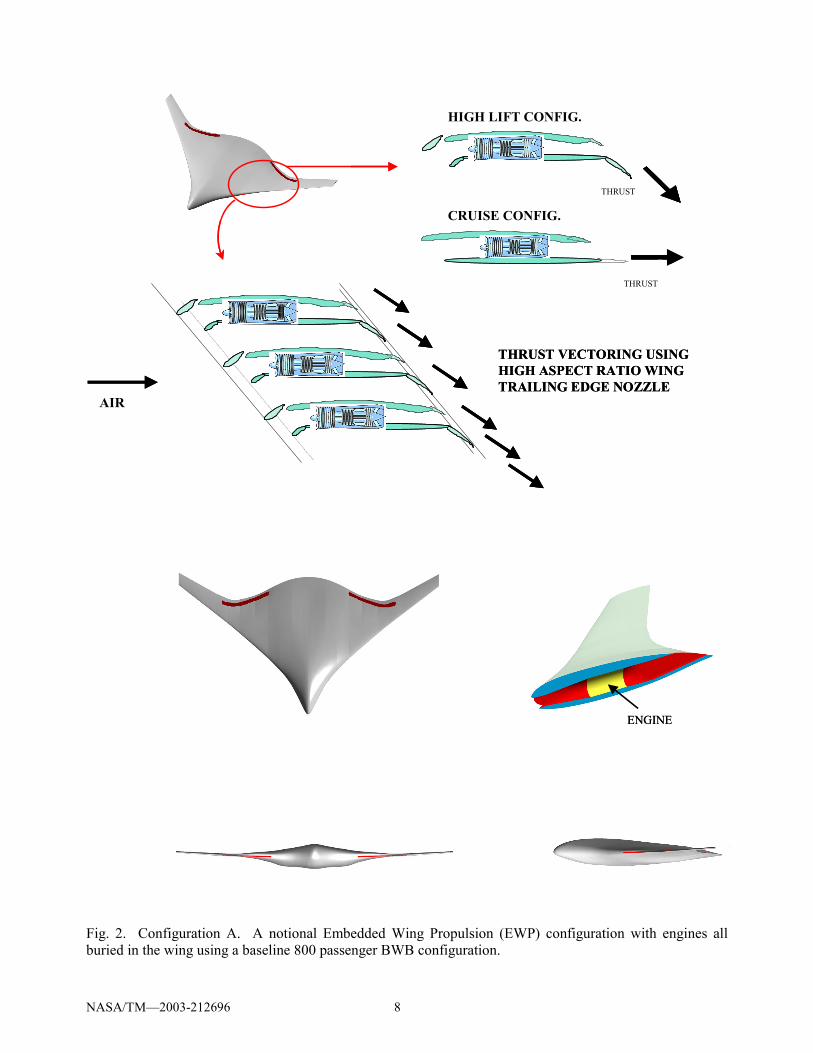
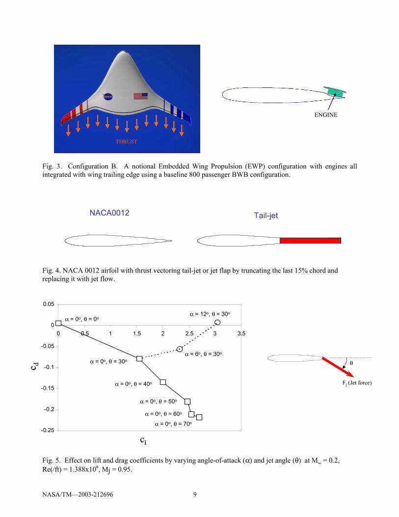
Fig. 3. Configuration B. A notional Embedded Wing Propulsion (EWP) configuration with engines all integrated with wing trailing edge using a baseline 800 passenger BWB configuration.
Fig. 4. NACA 0012 airfoil with thrust vectoring tail-jet or jet flap by truncating the last 15% chord and replacing it with jet flow.
Fig. 5. Effect on lift and drag coefficients by varying angle-of-attack (α) and jet angle (θ) at M∞ = 0.2, Re(/ft) = 1.388x10⁶, Mj = 0.95.
THRUSTTHRUSTTHRUSTTHRUST
ENGINEENGINE
NACA0012 Tail-jetNACA0012 Tail-jet
-0.25
-0.2
-0.15
-0.1
-0.05
0
0.05
0 0.5 1 1.5 2 2.5 3 3.5
c d
cl
α = 0o, θ = 30oα = 6o, θ = 30o
α = 12o, θ = 30o
α = 0o, θ = 70o
α = 0o, θ = 60o
α = 0o, θ = 50o
α = 0o, θ = 40o
α = 0o, θ = 0o
-0.25
-0.2
-0.15
-0.1
-0.05
0
0.05
0 0.5 1 1.5 2 2.5 3 3.5
c d
cl
α = 0o, θ = 30oα = 6o, θ = 30o
α = 12o, θ = 30o
α = 0o, θ = 70o
α = 0o, θ = 60o
α = 0o, θ = 50o
α = 0o, θ = 40o
α = 0o, θ = 0o
θ
Fj (Jet force)

NASA/TM�2003-212696 10
(a) Jet angle, θ = 30o.
(b) Jet angle, θ = 50o.
(c) Jet angle, θ = 70o.
Fig. 6. Mach number contours and surface pressure coefficient distribution at various jet angle, θ, and constant angle-of-attack, α = 0o (M∞ = 0.2, Re(/ft) = 1.388x10⁶, Mj = 0.95).
x / c
-cp
x / c
-cp
x / c
-cp

NASA/TM�2003-212696 11
(a) Angle-of-attack, α = 6o.
(b) Angle-of-attack, α = 12o.
(c) Angle-of-attack, α = 16o. Converged CFD solution was not obtained due to large flow separation.
Fig. 7. Mach number contours and surface pressure coefficient distribution at various angle-of-attack, α, and constant jet angle, θ = 30o (M∞ = 0.2, Re(/ft) = 1.388x10⁶, Mj = 0.95).
x / c
-cp
x / c
-cp

NASA/TM�2003-212696 12
Fig. 8. A baseline concept for Supersonic Transport (SST) with embedded propulsion system.
Fig. 9. A cross flow fan or transverse fan concept applied to aircraft wing.6
Notional DrawingNotional Drawing
Lockheed-Martin concept
Wing-Root Mounted Gas Generator
Fuselage
Transverse Fan Rotors Connected by Flex-Couplings or Universals
Wing-Tip Mounted Gas Generator
Lockheed-Martin concept
Wing-Root Mounted Gas Generator
Fuselage
Transverse Fan Rotors Connected by Flex-Couplings or Universals
Wing-Tip Mounted Gas Generator
Flow control (high C L/CD)
Distributed propulsion (u/ ue!1)
a
a
Flow control (high cl/cd)
e
a
aDistributed propulsion ( U/U∞ -> 1)
Flow control (high C L/CD)
Distributed propulsion (u/ ue!1)
a
a
Flow control (high cl/cd)
e
a
aDistributed propulsion ( U/U∞ -> 1)
This publication is available from the NASA Center for AeroSpace Information, 301–621–0390.
REPORT DOCUMENTATION PAGE
2. REPORT DATE
19. SECURITY CLASSIFICATION OF ABSTRACT
18. SECURITY CLASSIFICATION OF THIS PAGE
Public reporting burden for this collection of information is estimated to average 1 hour per response, including the time for reviewing instructions, searching existing data sources,gathering and maintaining the data needed, and completing and reviewing the collection of information. Send comments regarding this burden estimate or any other aspect of thiscollection of information, including suggestions for reducing this burden, to Washington Headquarters Services, Directorate for Information Operations and Reports, 1215 JeffersonDavis Highway, Suite 1204, Arlington, VA 22202-4302, and to the Office of Management and Budget, Paperwork Reduction Project (0704-0188), Washington, DC 20503.
NSN 7540-01-280-5500 Standard Form 298 (Rev. 2-89)Prescribed by ANSI Std. Z39-18298-102
Form Approved
OMB No. 0704-0188
12b. DISTRIBUTION CODE
8. PERFORMING ORGANIZATION REPORT NUMBER
5. FUNDING NUMBERS
3. REPORT TYPE AND DATES COVERED
4. TITLE AND SUBTITLE
6. AUTHOR(S)
7. PERFORMING ORGANIZATION NAME(S) AND ADDRESS(ES)
11. SUPPLEMENTARY NOTES
12a. DISTRIBUTION/AVAILABILITY STATEMENT
13. ABSTRACT (Maximum 200 words)
14. SUBJECT TERMS
17. SECURITY CLASSIFICATION OF REPORT
16. PRICE CODE
15. NUMBER OF PAGES
20. LIMITATION OF ABSTRACT
Unclassified Unclassified
Technical Memorandum
Unclassified
National Aeronautics and Space AdministrationJohn H. Glenn Research Center at Lewis FieldCleveland, Ohio 44135–3191
1. AGENCY USE ONLY (Leave blank)
10. SPONSORING/MONITORING AGENCY REPORT NUMBER
9. SPONSORING/MONITORING AGENCY NAME(S) AND ADDRESS(ES)
National Aeronautics and Space AdministrationWashington, DC 20546–0001
Available electronically at http://gltrs.grc.nasa.gov
November 2003
NASA TM—2003-212696
E–14199
WBS–22–708–87–19
18
Embedded Wing Propulsion Conceptual Study
Hyun D. Kim and John D. Saunders
Engine airframe integration; Propulsion system configurations
Unclassified -UnlimitedSubject Categories: 01 and 07 Distribution: Nonstandard
Prepared for the Vehicle Propulsion Integration Symposium sponsored by the NATO Research and Technology Agency,Warsaw, Poland, October 6–9, 2003. Responsible person, Hyun D. Kim, organization code 2400, 216–433–8344.
As a part of distributed propulsion work under NASA's Revolutionary Aeropropulsion Concepts or RAC project, anew propulsion-airframe integrated vehicle concept called Embedded Wing Propulsion (EWP) is developed andexamined through system and computational fluid dynamics (CFD) studies. The idea behind the concept is to fullyintegrate a propulsion system within a wing structure so that the aircraft takes full benefits of coupling of wingaerodynamics and the propulsion thrust stream. The objective of this study is to assess the feasibility of the EWPconcept applied to large transport aircraft such as the Blended-Wing-Body aircraft. In this paper, some of earlyanalysis and current status of the study are presented. In addition, other current activities of distributed propulsionunder the RAC project are briefly discussed.