Embed Size (px)
Citation preview
EMBEDDED THROUGH-SECTION SHEAR STRENGTHENING TECHNIQUE USING STEEL AND
CFRP BARS IN RC BEAMS OF DIFFERENT PERCENTAGE OF EXISTING STIRRUPS
Authors: Breveglieri M. 1, Aprile A.2, Barros J.A.O.3
1 Phd student, ENDIF, Dep. of Eng., University of Ferrara, 44121 Ferrara, Italy, [email protected]
2 Assistant Professor, ENDIF, Dep. of Eng., University of Ferrara, 44121 Ferrara, Italy, [email protected]
3 Full Professor, ISISE, Dep. of Civil Eng., Univ. of Minho, Azurém, 4810-058 Guimarães, Portugal, [email protected]
Abstract
The Embedded Through-Section (ETS) technique is a promising technique for the shear strengthening of
existing (RC) elements. According to this technique, holes are drilled through the beam section, and bars of steel
or FRP material are introduced into these holes and bonded to the concrete with adhesive materials. An
experimental program was carried out with RC T-cross section beams strengthened in shear using the ETS steel
bars and ETS CFRP rods. The research is focused on the evaluation of the ETS efficiency on beams with
different percentage of existing internal transverse reinforcement (ρsw=0.0%, ρsw=0.1% and ρsw=0.17%). The
effectiveness of different ETS strengthening configurations was also investigated. The good bond between the
strengthening ETS bars and the surrounding concrete allowed the yield initiation of the ETS steel bars and the
attainment of high tensile strains in the ETS CFPR rods, leading to significant increase of shear capacity, whose
level was strongly influenced by the inclination of the ETS bars and the percentage of internal transverse
reinforcement.
Key words: Reinforced Concrete Beams, Shear strengthening, ETS technique, Embedded Through-Section
Technique, ETS steel bars, ETS CFRP bars, Existing stirrups.
1. Introduction
To avoid brittle and unpredictable failures due to lack of shear resistance in RC elements, strengthening
techniques based on the use of fiber reinforced polymer (FRP) materials have been proposed and developed in

the last two decades [1–4]. The efficiency of these techniques relies on the bond of performance of concrete-
adhesive-FRP interfaces. It has been demonstrated that the Near Surface Mounted (NSM) technique assures
better bond conditions for the FRP strengthening systems than the externally bonded reinforcement (EBR)
technique due to the higher confinement applied by the surrounding concrete to the FRPs [5–8]. It was also
realized that as deeper is introduced a NSM FRP system into the groove opened on the concrete cover, as higher
is the strengthening effectiveness of this system [9,10]. The Embedded Through-Section (ETS) technique was
recently proposed for the shear strengthening or RC beams [11]. According to this technique, steel or FRP bars
are inserted into holes drilled through the cross section, and are bonded to the surrounding concrete with an
epoxy adhesive. In case of ETS technique, this concrete is able to provide a high confinement to the ETS bars,
which increases the bond strength. Furthermore, a larger concrete fracture surface is mobilized during the pullout
process of a ETS bar crossing the shear crack, when compared to the case of a NSM FRP strengthening system.
When concrete cover has not the bond strength requisites to guarantee the aimed strengthening effectiveness for
the EBR or NSM techniques, ETS strategy can be a technical and economic alternative since it mobilizes the
beam’s concrete core that is generally the less damaged zones of a beam. Significant increase of shear capacity
was pointed out by Valerio et al. [11,12] who investigated the use of the ETS technique for the shear
strengthening of RC existing bridges, and performed pullout tests for assessing the strengthening effectiveness of
adhesive materials, and different embedment lengths for the ETS bars. The shear stress transfer mechanism
developed in an ETS bar was studied by Barros et al. [13]. In this context, direct shear tests were executed with
the purpose of capturing the main features of FRP/steel ETS bars as shear strengthening systems. From these
tests it was verified that steel bars were notably effective for this purpose. Chaallal et al. [14] carried out
experimental tests to compare the shear strengthening effectiveness of the ETS, NSM and EBR techniques based
on the use of vertical CFRP bars applied on RC beams that were reinforced with different percentage of internal
steel stirrups. It was verified that the ETS technique has provided the highest strengthening efficiency, and it was
able to convert shear failure into a flexural failure. An experimental program was carried out by Barros and
Dalfré [15] with RC beams shear strengthened with ETS steel bars. The variables examined in this experimental
program were the width of the beam’s web, the percentage and inclination of the ETS bars, the spacing of steel

stirrups and their interaction with the strengthening bars. A significant increase of load carrying capacity was
obtained (up to 124%), proving that the use of ETS steel bars can be a very effective and cost-competitive shear
strengthening technique. The beams with the higher percentage of ETS bars have failed in bending, despite the
very high percentage of flexural reinforcement used. The ETS technique can also be extended to punching shear
strengthening of concrete slabs [16,17].
Shear is a complex phenomenon due to the high number of parameters that affect shear behavior, which justifies
to be not yet completely addressed. The parameters that influence the shear behavior of a strengthened RC
element are already identified [18–20]. International guidelines on the use of FRPs [21–24] take into account
only a restricted number of factors, ignoring the influence, for instance, of existing transverse reinforcement. The
interaction between the strengthening system and the existing internal transverse reinforcement has been
investigated for the EBR and NSM techniques, and some design approaches have been proposed in these respect
[25–30].
The present work aims to contribute to a deeper understanding of the ETS shear strengthening mechanisms, and
the susceptibility of these mechanisms to the interaction between ETS bars and existing steel stirrups. The
ultimate purpose of this work is to provide useful data for the establishment of design guidelines on the shear
strengthening of RC beams using the ETS technique. The experimental program was conceived for assessing the
influence on the ETS shear strengthening effectiveness of the percentage, inclination and material type of the
ETS systems. For this purpose, three series of RC T-cross section beams with different percentage of internal
transverse reinforcement (ρsw=0.0%, ρsw=0.1% and ρsw=0.17%) were tested. The experimental program is
described in detail and the relevant results are presented and discussed.
2. Experimental program
2.1 Test series
Fig.1 presents the geometry and the reinforcement arrangements of the nineteen T cross section beams of the
experimental program. The reinforcement system was designed according to the Eurocode 2 [31], using an high

percentage of longitudinal reinforcement (ρsl=2.79%) in order to force the occurrence of shear failure mode for
all the beams of the experimental program. To localize shear failure in one of the beam’s shear spans, a three
point load configuration was selected, with a different length of the beam shear spans. The monitored beam span
(L1=0.9 m) is 2.5 times the effective depth of the beam’s cross section (L1/d=2.5), since according to the
available research [32], beyond this limit the arch effect is negligible. To avoid shear failure in the L2 beam span,
steel stirrups ϕ8@90 mm were applied in this span. Different shear reinforcement systems were applied in the L1
beam’s span of the tested beams. In fact, the experimental program consisted of the following three series of
beams: 0S-Series that does not have conventional steel stirrups; 2S-Series that has steel stirrups ϕ6@300 mm,
corresponding to a shear reinforcement ratio ρsw =0.10%, 4S-Series that has steel stirrups ϕ6@180 mm,
corresponding to a shear reinforcement ratio ρsw =0.17%, where:
swsw
w sw
A
b s (1)
being Asw the cross sectional area of the two legs of a steel stirrup, ssw the spacing of the steel stirrups, and
bw=180 mm the width of the beam’s web.
Each series has a reference beam without any strengthening system (Fig. 1, Fig.2), and four beams with different
ETS strengthening configurations (Fig. 3). The investigated parameters are the shear strengthening ratio (ρfw) and
the inclination (90°, 45°) of the ETS bars, as well as the influence of the percentage of existing steel stirrups. In
particular, the shear strengthening ratio of the ETS steel bars and ETS CFRP rods was defined as follows:
sin
fwfw
w fw f
A
b s
(2)
where Afw is the cross sectional area of ETS bar, and sfw and αf represent the spacing and inclination of this bar,
respectively.
The influence of the material type of the ETS bars used for the strengthening was also investigated, by having
beams strengthened with CFRP and steel bars in both 2S and 4S series of beams. The diameter of the ETS steel
and CFRP bars was 10 and 8 mm, respectively. A smaller diameter for the CFRP bar was chosen in order that
the estimated force at the debonding of this bar was similar to the force at yield initiation of the steel bar. Based
on previous experiences [11,14,15], it was considered for the strain at debonding of this type of CFRP bars a
value in the interval 0.55-0.6%. Table 1 indicates the designation adopted for each beam and the strengthening
configurations, namely, the number of applied ETS bars, inclination, spacing, shear strengthening ratio (ρfw), as
well as the percentage of steel stirrups (ρsw ) and total shear reinforcement (ρsw +ρfw ) calculated from Eq (1) and
Eq (2). Fig. 3 shows the strengthening configurations of the two tested series. As previously demonstrated by
Barros and Dalfré [15], the effectiveness of the ETS bars is higher if they are placed in between existing stirrups.
Following this approach, the strengthening arrangements indicated in Table 1 and Fig. 3 were adopted, leading
to four different ρfw values. The ETS strengthening ratio varied between 0.15% (ETS vertical bars spaced at 300
mm) and 0.34% (ETS bars at 45° and spaced at 180 mm). Two strengthening ratio values were adopted in the
beams strengthened with ETS CFRP bars, ρsw= 0.16 (vertical bars spaced at 180 mm), and ρsw=0.22 (bars at 45°
spaced at 180 mm)
2.2. Material properties
The concrete average compressive strength (fcm) of the beams was evaluated at 28 days and at the age of the
beams’ test, by carrying out direct compression tests on cylinder specimens of 150 mm diameter and 300 mm
height according to EN 206-1 (2004) [33]. It was obtained an fcm equal to 24.7 and 29.7 MPa at 28 days and at
the day of the test (approximately 255 days), respectively, for the first batch (0S-Series and 2S-Series) and 27.6
and 32.3 MPa, at 28 days and at the day of the test (approximately 250 days) for the second batch (4S-Series and
CFRP ETS strengthened beams), respectively. For the internal reinforcement of the beams, high bond steel bars
of 6, 10, 8, 12, and 24 mm diameter were used. The steel class is B 450 C (fyk =450MPa) according to the Italian
Construction Code. [34]. The yield stress and tensile strength were obtained by means of uniaxial tensile tests
performed according to recommendations of UNI EN ISO 6892-1:2009 [35]. For the steel bars of 6, 8, 10, 12
and 24 mm diameter it was obtained an average yield stress of 574 (εsy= 0.287%), 505 (εsy=0.253%), 549 (εsy=
0.275%), 527 (εsy= 0.264%) and 598 (εsy= 0.299%) MPa, and an average tensile strength of 667, 594, 642, 617
and 708 MPa, respectively. The adopted ETS steel bars were of the same class of the bars used for the flexural
reinforcement and steel stirrups applied in the beams. To bond the ETS steel bars to the concrete substrate the

Sikadur 32 N epoxy based adhesive was used. The tensile behavior of this adhesive was characterized by
carrying out direct tensile tests according to the ISO 527-2 [36], having been obtained an average tensile strength
of 20.7 MPa and an elasticity modulus of 3.27 GPa. The pultruded carbon fiber sandblasted 8mm rod,
MasterBrace BAR 8 CFS [37], has an elasticity modulus of 130 GPa and an ultimate strain of 1.8 %.
2.3. Strengthening technique
To simplify the drilling process and to avoid the possibility of intersecting the longitudinal bars, the execution of
the ETS strengthening process was executed with the beam’s web turned upward. The ETS strengthening
technique was composed of the following steps: (1) Holes of 16 mm diameter for the ETS steel bars, and holes
of 14 mm for the ETS CFRP bars were drilled in the beam core. The holes length was defined by preserving 20
mm of intact concrete cover at the lower side of the beam, in order to avoid the adhesive flow through the
bottom part of the hole. During the drilling process the concrete dust was aspired using a vacuum system. (2)
The holes were cleaned by using an helicoidally steel brush capable of removing the particles from the walls of
the hole, which were then eliminated by the vacuum system; the cleaning procedure was repeated until the dust
was definitely removed. (3) The epoxy resin was prepared according to the recommendations of the supplier, and
was slowly poured into the holes. (4) The ETS bars were cut in the desired length, cleaned with acetone, and
were slowly introduced into the holes removing the resin in excess. To guarantee a proper curing of the adhesive,
the beams were tested at least two weeks after the ETS application.
2.4 Test set up and monitoring system
Fig. 4 shows the position of the displacement transducers (LVDTs) and force transducers used for measuring the
beam’s deflection and applied/reaction forces, respectively. The LVDTs were supported in a bar fixed at the
beams supports’ sections in order to register displacements only caused by the deflection of the beam. The
displacement transducer TR1 was used to control the tests at a displacement rate of 10 µm/s up to the failure of
the beams. The beams were loaded under three-point bending configuration with a shear span of 900 mm. The
applied load (F) was measured using a force transducer of ±750 kN capacity and accuracy of ±0.1%. A second
force transducer of ±500 kN capacity and 0.1% accuracy was under the support corresponding to the longer span
(L2) to complement the information for a full assessment of the shear force in each span of the beam. To obtain
the strain variation in steel stirrups and ETS bars, electrical strain gauges (SGs) were bonded on selected cross
sections of stirrups and ETS bars that have the highest probability of providing the largest contribution for the
shear strengthening of the RC beam. Eight and five SGs for each beam of series without stirrups (0S-Series) and
beam with stirrups (2S and 4S Series), respectively, were installed on ETS bars according to the configuration
represented in Figs 5a and 5b. In ETS CFRP strengthened beams, six SGs were installed on a CFRP bar, and two
SGs were applied on an internal steel stirrups. The monitoring SGs system in CFRP strengthened beams was
slightly different of the one adopted in the steel strengthened beams, and the position of the SGs is indicated in
Fig.5c.
3. Results
3.1 Load carrying capacity of the tested beams.
The load (F)-deflection (uL) diagrams are presented Fig.6 for 0S Series, 2S Series and 4S Series. All the beams
showed the same behavior up to the formation of the first diagonal crack, that has formed at an approximate load
of 113 kN (uL=0.98mm), 100 kN (uL=0.91mm) and 135 kN (uL=1.37mm) in case of the reference beams 0S-Ref,
2S-Ref and 4S-Ref, respectively. Fig. 7 shows the failure crack patterns obtained for all the tested beams. As
already observed in beams that have been strengthened in shear with carbon fiber reinforced polymer (CFRP)
laminates, installed according to the NSM technique [38], the stiffness degradation of the ETS strengthened
beams is generally smaller than that of the reference beams. The ETS steel bars bridging the shear cracks
surfaces offer resistance to crack opening and sliding, enhancing concrete’s contribution to the shear resistance
due to the aggregate interlock effect, which leads a higher load carrying capacity after shear crack initiation. The
ETS strengthening technique increased significantly the maximum load carrying capacity and ultimate deflection
capacities of the beams, whose performance level depends on the shear reinforcement/strengthening
arrangement. All the beams exhibited a shear failure mode, since a quite high flexural reinforcement was
adopted in order to avoid flexural failure mode. The beam with the highest load carrying capacity (4S-C180-45)

has presented a mixed-mode shear-flexural failure, and its crack pattern was characterized by the opening of two
large diagonal cracks, followed by the crushing of the concrete at the loaded section at failure (Fig.7). The main
results of the experimental tests are presented in Table 2, where Fmax is the maximum load attained by the beams
and uLmax is the displacement in the loaded section at Fmax. The strengthening efficiency of the ETS technique can
be evaluated by considering the ΔF/FRef ratio, where FRef is the maximum load of the reference beam, and
ΔF=Fmax-FRef is the increase of maximum load provided by each ETS arrangement. The Table 2 also includes the
maximum shear force Vmax (=0.6 Fmax ) applied in the L1 beam’s span (Fig. 1) and the resisting shear force
provided by the ETS arrangement, Vf(exp). This last term was determined by considering the shear resistance in
the 0S-Ref, 2S-Ref and 4S-Ref reference beams, by assuming as valid the principle that the shear resistance of a
beam reinforced with steel stirrups and strengthened with ETS bars is the addition of the contributions of the
concrete, steel stirrups and ETS bars. The last two columns in this table include, respectively, the tangent
(CDCtang) and the average (CDCavg) inclination of the failure shear crack (CDC), whose evaluation process is
schematically represented in Fig. 7, for 0S-Ref beam. For the evaluation of the CDCtang, an auxiliary horizontal
line at half distance from the longitudinal reinforcement to the bottom surface of the beam’s flange (d1 represented
in 0S-Ref beam in Fig. 7) was introduced; then the point of its interception with the CDC was determined. The
CDCtang is the inclination of the CDC at this point of interception. The (CDCavg) is determined by connecting the
points of the interception of the CDC with the bottom surface of the beam’s flange and the longitudinal
reinforcement. According to the obtained results, the (CDCtang) was usually higher than (CDCavg). The values of
(CDCtan) have ranged from 34° to 73°. By considering all the tested beams, an average value of CDCavg = 45°
was obtained. It is possible to notice that the beams with the highest percentage of shear reinforcement (ρws+ρwf)
and the CFRP strengthened beams exhibited higher inclinations of the CDCavg. 2S-S180-90 and 2S-C180-90
beams presented high inclinations of critical diagonal crack, probably due to the less evenly distributed of the
shear reinforcements. Fig. 7 clearly shows that the number of diagonal cracks increased with the percentage of
transverse steel reinforcement.
The load vs. deflection relationship of the beams of 0S-Series is indicated in Fig. 6a. This series is characterized
by the absence of stirrups in the strengthened shear span (ρws= 0.0%). Due to the detrimental interaction effect
between existing steel stirrups and strengthened systems in the context of the shear strengthening effectiveness
[27], the beams of this series presented the highest strengthening efficiency amongst the tested series, with an
increase of load carrying capacity that ranged from 40% to 136%. For the ETS vertical bars, the beams with the
lowest percentage of ETS bars, ρfw = 0.15% (0S-S300-90), and with the highest ρfw= 0.24% (0S-S180-90)
presented an increase of load carrying capacity of 39.5% (Fmax= 217.8 kN; uLmax = 4.37 mm) and 64.6% (Fmax=
256.8 kN; uLmax 4.31 mm), respectively. The highest increase of load carrying capacity was obtained in the
beams with ETS bars inclined at 45°. In fact the beam with the lowest ρfw = 0.24% (0S-S300-45) and with the
highest ρfw= 0.34% (0S-S180-45) presented an increase of load carrying capacity of 123.4% (Fmax=348.6 kN) and
of 136.3% (Fmax= 368.8 kN; uLmax =6.56 mm), respectively. This indicates that the inclination of the ETS bars
seems to have a higher contribution for the strengthening effectiveness that the spacing of these bars, as long as
this distance assures that a CDC is crossed by an effective ETS bar (with an enough bond length to avoid
premature debonding), which is in agreement with the tendency observed in the NSM technique [27].
The load vs. deflection relationship of the beams of 2S-Series is depicted in Fig. 6b. This series is shear
reinforced with 2-arms ϕ6mm steel stirrups @300 mm (ρws= 0.10%). For the ETS vertical bars, the beams with
the lowest percentage of ETS bars, ρfw = 0.15% (2S-S300-90), and with the highest percentage, ρfw= 0.24% (2S-
S180-90), have presented an increase of load carrying capacity of 30.4% (Fmax= 315.7 kN; uLmax =5.32 mm) and
68.1% (Fmax= 406.8 kN; uLmax 8.27 mm), respectively. Like already occurred in the beams of the 0S-Series, in the
2S-Series the highest strengthening effectiveness has occurred in the beams with ETS bars inclined at 45°. In
fact, the beam with the lowest percentage, ρfw = 0.24% (0S-S300-45), and with the highest percentage, ρfw=
0.34% (2S-S180-45), presented an increase of the load beam carrying capacity of 68.2% (Fmax=407.1 kN; uLmax
7.03 mm) and 108.5% (Fmax= 504.7 kN; uLmax =8.37 mm), respectively.
The load vs. deflection relationship of the beams of the 4S-Series is illustrated in Fig. 6c. This series is shear
reinforced with 2-arms ϕ6mm existing steel stirrups @180 mm (ρws= 0.17%). For the ETS vertical bars, the
beams with the lowest percentage of ETS bars, ρfw = 0.15% (4S-S300-90), and with the highest percentage, ρfw=
0.24% (4S-S180-90), presented an increase of load carrying capacity of 4.8% (Fmax= 370.9 kN; uLmax = 7.43mm)
and 16.8% (Fmax= 413.2 kN; uLmax = 6.32mm), respectively. The decrease of the shear strengthening

effectiveness with the increase of existing shear reinforcement is quite evident, and will be discussed in more
detail in Section 5. Furthermore, for configuration 4S-S300-90 a Vf(exp) of 10.3 kN indicates that the contribution
provided by the only ETS bar crossed by the shear crack was low, due to its small resisting bond length (Fig7).
The results of this beam showed the importance of the adopted strengthening geometry, revealing that strengthen
elements should be placed in between stirrups [15,28]. For the beams with ETS bar inclined at 45° a higher
increase of load carrying capacity was obtained. In fact, the beams with the lowest percentage of ETS bars, ρfw =
0.24% (4S-S300-45), and with the highest percentage, ρfw= 0.34% (4S-S180-45), presented an increase of load
carrying capacity of 56.1% (Fmax=552.4 kN; uLmax = 12.03 mm) and 60.1% (Fmax= 566.4kN; uLmax =11.01mm),
respectively. These results indicate that by increasing the percentage of existing steel stirrups, the influence of
the inclination of the ETS bars in terms of shear strengthening effectiveness becomes larger, while the influence
of the spacing of ETS bars becomes smaller.
The shear strengthening effectiveness of CFRP bars was also investigated, by strengthening two beams of both
2S-Series and 4S-Series. The load vs. deflection relationship of the beams strengthened with ETS CFRP bars is
indicated in Fig. 6b for 2S-Series and in Fig. 6c for 4S-Series. For the CFRP vertical bars, ρfw= 0.16%
(CFRP180-90), the beams presented an increase of load carrying capacity of 53.1% (Fmax= 370.49 kN; uLmax =
6.89 mm) and 6.5% (Fmax= 376.88 kN; uLmax = 6.2 mm) for 2S- and 4S-Series, respectively. For the ETS CFRP
bars inclined at 45°, ρfw= 0.22% (CFRP180-45), the beams presented an increase of load carrying capacity of
120.9% (Fmax= 534.69 kN; uLmax = 9.53 mm ) and 74.4% (Fmax= 616.86 kN; uLmax = 12.03 mm ) for 2S- and 4S-
Series, respectively. A lower strengthening performance was observed for the vertical CFRP bars when
compared to the vertical steel bars due the strengthening configuration. In fact, the available bond length of the
CFRP bar crossed by the CDC was not sufficient to develop high tensile strains in this type of bars. However,
when the strengthening configuration provided an adequate bond length, as was the case of inclined bars, a
higher load carrying capacity was obtained by using CFRP bars instead of steel bars. The results obtained in the
beams strengthened with ETS CFRP bars demonstrate that the decrease of the shear strengthening effectiveness
with the increase of the reinforcement ratio of existing steel stirrups occurs regardless of the type of material
adopted for the ETS bars.

3.2 Strains in the ETS bars/rod and steel stirrups.
The relationships between the force applied in the beams and the strains registered in the most representative
SGs installed in the monitored ETS bars and stirrups are shown in Fig. 8, while in Table 3 are included the
relevant results, where εFmax is the strain measured at Fmax, while εmax is the maximum strain recorded in the ETS
bars and stirrups. For the εmax it is also provided the value of the uL/uLmax parameter, in order to indicate if εFmax
has occurred in pre- (uL/uLmax <1) or post-peak (uL/uLmax >1) phase of the beam’s force-deflection response. The
recorded strain values are quite dependent on the distance between the SG and the shear failure crack. This effect
is quite visible in beams strengthened with vertical ETS bars, in which relatively high strain values have been
measured in zones of the ETS bars crossed by a shear crack (Figs 8a and 8d). For instance, large strains at Fmax
have been recorded in SG No.4 of the 0S-S180-90 beam (0.59% at Fmax) (Fig8a), SG No.8 of the 2S-C180-90
beam (0.67% at Fmax) (Fig8d), SG No.7 for the 4S-S180-90 (ε=88% at Fmax). The designation attributed to the
strain gauges in Table 3 for the ETS bars and steel stirrups (second and third column) is represented in Figs. 5
and 8 in order to highlight the relative position between the SGs and the shear cracks, and to help a better
interpretation of the obtained results. Furthermore, the strain values are quite dependent on the available bond
length of the elements they are installed. If the available bond length is relatively small, the steel bars cannot
attain the yield strain due to slip occurrence, as was the case of SG No.4 of the 4S-S180-90 beam (ε=0.04% at
Fmax) and SG No.1 of the 0S-S180-90 (ε= 0.16% at Fmax). For the same reason, CFRP bars can record low strain
even if the bars are crossed by the critical shear crack, as was the case of SG No.4 of the 2S-C180-90 beam
(ε=0.27% at Fmax).
Higher strains have been recorded in both inclined ETS steel and CFRP bars, thanks to the adopted strengthening
configuration that provided longer force transfer length and, consequently, higher increase of load carrying
capacity. It was verified that steel ETS bars have reached the yield strain in the sections where they were crossed
by the critical shear crack and also by a secondary diagonal crack, as occurred in the beams 0S-S300-45, 0S-
S180-45, 2S-S300-45, 2S-S180-45, 4S-S300-45, and 4S-S180-45 (Fig. 8). In some of the tested beams, the
excellent bond conditions provided by the concrete core allowed the steel yield strain to be exceeded in more

than one section of the same ETS bar crossing shear cracks, such was the case, for instance, 4S-S300-45 beam
(Fig.8c) with ε=0.91% in SG No.6 at 0.75 uL/uLmax and ε=0.90% in SG No.8 at 0.82 uL/uLmax). By using inclined
bars, strain values higher than 0.8% have been usually recorded in at least one of the ETS steel bars. In all the
monitored elements of the strengthened beams with inclined CFRP bars, as is the case of beams 2S-C180-45 and
4S-C180-45, higher strains were recorded due to the formation of diffuse crack patterns (Figs. 8e and 8f). For
instance, in the ETS4 and ETS3 monitored sections of beams 2S-C180-45 and 4S-C180-45, a relatively high
average strain of ε=0.9% was obtained. The higher number of cracks is a consequence of the higher percentage
of the ETS strengthening ratio and the larger effective bond length (in case of inclined ETS bars) that can
mobilizes simultaneously bond and concrete resisting fracture mechanisms [39]. The maximum strain of ε=1%
at 0.83 uL/uLmax was measured in the SG No.7 of beam 2S-C180-45. Considerable strains were also attained in
case of a reduced bond length (ε=0.61% at 0.63 uL/uLmax in SG No.4 of beam 2S-C180-45). Higher strains were
generally recorded in CFRP bars than in steel bars, due to the lower elasticity modulus of the CFRP.
Steel stirrups showed a trend in terms of strain variation similar to the ETS bars, attaining relatively high strains
in the sections crossed by a diagonal crack, as was the case of SG No.3 in beam 4S-S300-45 (ε=0.89% at 0.68
uL/uLmax), or SG No.3 for beam 4S-C180-45 (ε=0.79% at 0.78 uL/uLmax). Moreover, the excellent anchorage
conditions provided by the closed configuration of the stirrups, as well as its smaller diameter (when compared
to the ETS steel bars diameter), have assured the attainment of the yield strain in several sections monitored with
SG. In some of the beams, the steel stirrups have even attained its rupture (2S-S300-45, 4S-S180-90,
2SCFRP180-45, 4S-C180-45).
3.3 Failure modes
The ETS shear strengthening systems have failed by the debond at the bar/adhesive interface. Due to the higher
confinement provided to the ETS bars by the web-flange surrounding concrete under compression, debonding
which was the governing failure mode occurred in the bond length of ETS bars localized in the bottom part of
the beam’s cross section (apart 0S-S300-90, see Fig. 7). This type of failure has been observed either in steel
(Fig. 9a) as well as in CFRP bars (Fig. 9b). In case of ETS steel bars, it was possible to observe that the ribs of

these bars have scratched the surrounding epoxy adhesive, Fig. 9c. Despite this observed behavior, the bond
performance was capable to mobilize the yield stress of the steel bars, and assured relatively high tensile strains
in the CFRP bars, as reported in the previous section. This type of failure mode might justify the relatively low
maximum strains recorded in the vertical ETS bars, and consequently the lower shear strengthening
effectiveness when compared to the same strengthening configuration but using steel bars (Table 2). In fact,
since the average direction of the shear failure cracks is about 45° with the beam’s axis (Table 2), during the
opening and sliding process of this type of cracks, the vertical and inclined ETS bars that cross these cracks are
submitted to axial and transversal force components. As already observed in a previous study [40], due to this
latter component, the axial force transferred from the bar to the surrounding material increases, leading the ETS
bars to scratch the surrounding epoxy adhesive. This scratching effect was also observed in the face of the CFRP
bars, due to the relatively low shear resistance of the external layer of these bars, when compared to the ribs of
the steel bars. The combined action of tensile and transversal forces on the bar has led, in most of cases, to the
peeling-off of the external layer of the CFRP bars (Fig. 9d). The post-test inspection of the failure modes in 2S-
C180-45 has revealed that the bars have ruptured, probably not because the ultimate strain was attained, but a
consequence of the combined tensile-shear forces applied in the bar at crack section. The type of failure
characterized by the loss of bond between the steel end epoxy adhesive was also found in the bond test
conducted by [11], and [41]. The types of failures reported by [42], namely, concrete fracture, and mixed
concrete-fracture-debonding were not observed in the present experimental program. The concrete fracture was
not observed due to the relatively high confinement of the core concrete surrounding the ETS bars when using
the ETS technique. It is also possible to observe that the group effect, i.e. the tendency for the detachment of the
concrete cover with the increase of the shear strengthening percentage, observed when using the NSM technique
[38,43,44], did not occur in the ETS technique. Due to the scratching of the epoxy adhesive, the maximum strain
recorded in the ETS bars never attained the steel ultimate strain, and therefore the rupture of the steel ETS bars
have never occurred. However, in case of the steel stirrups, due to the excellent anchorage conditions provided
by its closed shape, the steel rupture was observed (see. § 3.2).

4. Influence of the percentage and inclination of the ETS strengthening.
Fig.10 represents the relationship between the strengthening effectiveness ratio, ΔF/FRmax, provided by the ETS
strengthening arrangement, and the total percentage of transverse reinforcement (ρsw+ ρfw) (see also Tables 1 and
2). The ρsw+ρfw percentage is in the range of 0.15% to 0.52 %, while the ρfw is in the interval of 0.15% to 0.34%.
Fig. 10 clearly shows that the shear strengthening effectiveness decreases with the increase of ρsw+ρfw. It is also
visible that most effective configurations are obtained by adopting inclined ETS bars, and a marginal shear
strengthening effectiveness is obtained when vertical ETS bars are applied in RC beams with a reinforcement
ratio of steel stirrups higher than of about 0.17%. The dashed lines identify the tendency lines of beams with the
same strengthening solution and different reinforcement ratio, pointing out the importance of the internal shear
ratio on the evaluation of the strengthening effectiveness (see § 5). The higher shear effectiveness showed by the
ETS inclined bars can be justified by the orientation of the diagonal cracks that tends to be almost orthogonal to
the ETS bars. Furthermore, for vertical ETS bars, the total resisting bond length of the ETS system is lower than
the one for the inclined bars. As demonstrated in [39,42], in the case of shear strengthening elements of non-
closed geometric configuration, such is the case of EBR and NSM reinforcements, the effective bond length has
a decisive and governing importance on the shear strengthening effectiveness, since a bond length less than the
critical one limits the strengthening effectiveness of the system. To have a comprehensive understanding on the
influence of the investigated parameters, the information available in previous works [11,14,15] have been
considered. From this latter tests only the data regarding beams that failed in shear was considered, which is
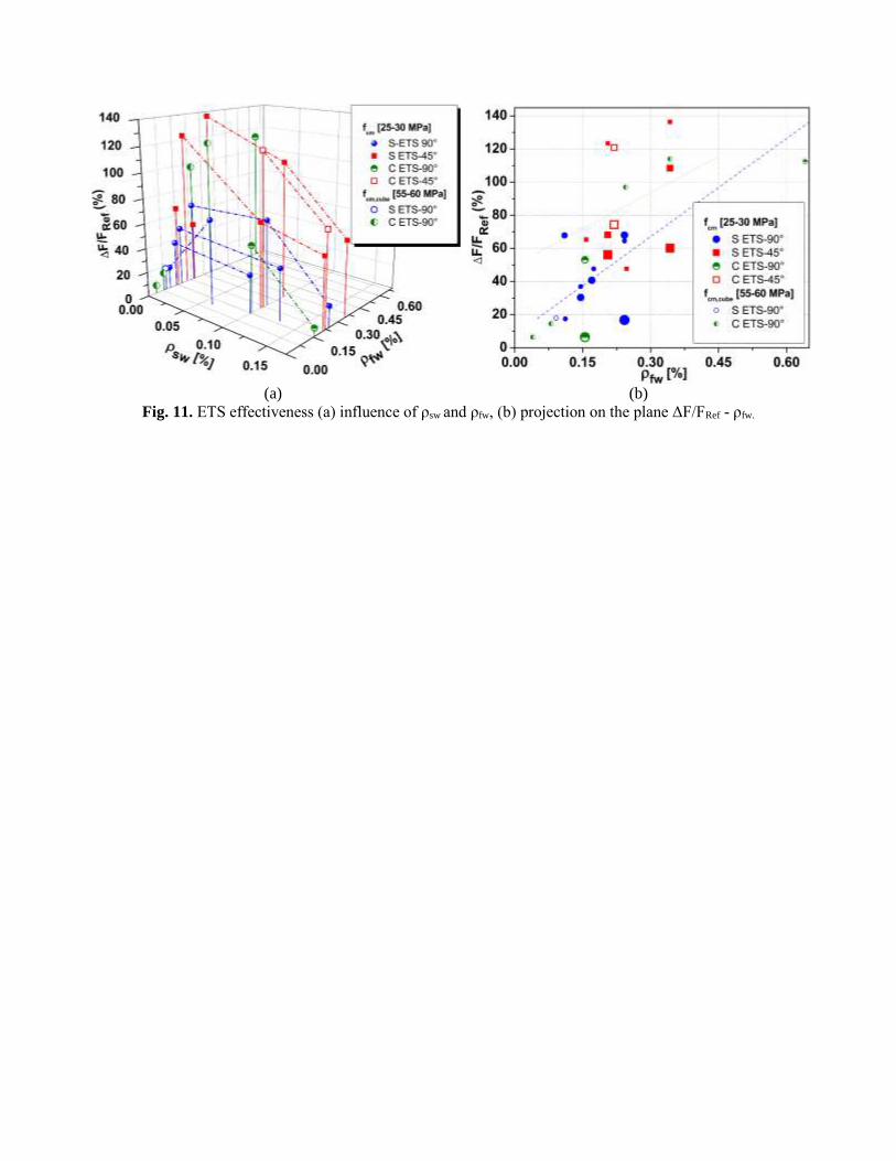
presented in Table 4 and Fig 11. The ρsw of the analyzed beams is in the range of 0.0 to 0.17 % and ρfw in the
interval of 0.04 to 0.64%. Fig. 11a shows the influence of ρsw and ρfw on the shear strengthening effectiveness of
RC beams strengthened with vertical and inclined ETS bars. It is visible the higher strengthening effectiveness
of inclined ETS bars, and a tendency for an increase of this effectiveness with ρfw, while the opposite happens
with the increase of ρsw. By projecting the results presented in Fig.11a on a ΔF/FRef - ρfw plane, and attributing to
the marker a size diameter proportional to the ρsw of the beam it represents, the previous conclusions can be also
extracted. A relatively high shear strengthening effectiveness with vertical CFRP bars was obtained by [14], but
using an abnormal high shear strengthening ratio (ρfw=0.64%). Valerio et al. [11] have also obtained similar high

shear strengthening effectiveness with smaller strengthening ratio (ρfw=0.24% to 0.34%), but using higher
concrete strength class (fcm,cube= 55 to 60 MPa - cube strength -, instead of fcm=25 MPa [14]), which reveals the
favorable effect of concrete strength on the shear strengthening performance. However, the results also indicate
that when the shear strengthening ratio is relatively small, the influence of the concrete strength on the shear
strengthening effectiveness is marginal due to the inexistence of interaction between ETS bars and smaller stress
field applied by ETS bars to the surrounding concrete. The trend lines of the results corresponding to the inclined
and vertical ETS bars (dotted and dashed line, respectively) evidence the higher effectiveness of the former bars.
The inclination of the trend line is higher for vertical ETS bars, which might be justified by a high number of
beams tested without shear reinforcement for this strengthening arrangement. From the results in Figures 10 and
11, the inclined ETS CFRP bars provided higher effectiveness than inclined steel bars of similar ρfw and ρsw, but
a comprehensive cost competitiveness evaluation of these strengthening solutions should be made for a
sustainable decision of the most appropriate one.
5. Influence of the existing shear reinforcement on the ETS strengthening effectiveness
As already demonstrated in beams strengthened with the ETS [14,15], EBR and NSM techniques [44–47], the
effectiveness of the ETS strengthening system decrease with the increase of the ρsw. Fig. 11 show this clear
tendency for the ETS strengthened beams. This detrimental effect was more pronounced in case of vertical ETS
bars; for instance in the case of the presented work, in ETS steel bars, spaced at 180mm, the ΔF/FRmax can
decrease up to 74% (by comparing the results of 0S-Series and 4S-Series). The results presented in Fig. 11
clearly show that the shear strengthening effectiveness is influenced by the shear reinforcement ratio of existing
steel stirrups. The detrimental effect induced by the presence of stirrups was recently discussed and a parameter
was proposed to simulate this effect [25,30]. In the present work it was verified that the stirrups have yielded,
even in the beams with the highest ρsw and ρfw. This indicates that ETS technique using steel bars can mobilize
integrally the strength capacity of both shear reinforcements, and consequently, the above parameter can be
neglected in this technique. In shallow RC beams shear strengthened with ETS steel bars, the resisting bond
length of those bars crossed by the critical shear crack may be not enough to mobilize its yield strain. In this case

the applicability of a reduction parameter can be justified. However, no sufficient experimental data is actually
available to propose a recommendation for this parameter. Fig. 12 compares the ΔF/FRmax obtained when using
ETS, NSM and EBR techniques, by considering the results obtained in previous experimental programs by Dias
and Barros [48], where similar RC beams were tested (ρsw =0.1 and ρsw =0.17%). The highest strengthening
efficiency of the ETS technique is clearly visible, mainly when using inclined ETS bars.
6. Conclusions
An experimental program on reinforced concrete (RC) T cross section beams shear strengthened with a recent
technique denominated Embedded Through-Section (ETS) was described, and the relevant results are presented
and discussed. The influence of the percentage of existing steel stirrups (ρsw) on the ETS shear strengthening
effectiveness when using ETS steel or carbon fiber reinforced polymer (CFRP) bars was investigated. The
inclination of these bars (90° and 45°) on this effectiveness was also analyzed. For this purpose three series of
beams with different ρsw (0.0, 0.10, and 0.17%) were tested.
From the obtained results it can be concluded that in general, a significant increase of load carrying capacity was
obtained by using the proposed technique, regardless the material type of ETS bars. Vertical ETS bars provided
an increase of load carrying capacity in the interval of 5% to 68%. The inclined ETS bars have assured a higher
strengthening effectiveness, since an increase of load carrying capacity from 53% to 136% was obtained. The
inclined ETS bars were also more effective in assuring larger deflection capacity at the failure of the beams. The
higher effectiveness of inclined ETS bars is attributable to the larger available resisting bond length, and their
better orientation regarding the inclination of the shear failure crack (almost mutually orthogonal).
When comparing the results from the series of beams with different ρsw it was verified that the strengthening
effectiveness has decreased with the increase of ρsw, and this tendency was more prone in the series with vertical
ETS bars. Information in this respect was collected from available bibliography, which has confirmed the
aforementioned tendency.

By comparing the shear strengthening effectiveness obtained with the ETS technique proposed in the present
work and the one assured by using the externally bonded reinforcement (EBR) and the near surface mounted
(NSM) techniques it was verified that the former one is more effective.
In fact, due to the good bond conditions of ETS bars assured by the concrete core of the beams, which also
introduced some favorable confinement to these bars, those made of steel have yielded, and the CFRP bars have
attained a relatively high maximum tensile strain, mainly the inclined ones. For similar shear strengthening ratio,
the CFRP bars provided higher shear strengthening effectiveness than steel bars, due to the larger ultimate force
capable to be mobilized in incliend bars. It was also verified that the steel stirrups have exceeded its yield strain,
even in the beams with the highest percentage of steel stirrups.
Taking into account the high level of shear strengthening effectiveness obtained in this experimental program, it
can be concluded that ETS can assure ductile flexural failure mode in RC beams susceptible to brittle shear
rupture. Moreover the ETS technique based on the use of steel bars is a cost competitive and sustainable solution
for the shear strengthening of RC elements, and much less susceptible to the detrimental effect of high
temperature than when using FRP systems. Corrosion of these bars can be avoided by providing a cement based
cover at the bars' extremities.
Acknowledgements
The authors wish to acknowledge Elletipi S.r.l. (Ferrara, Italy) for supporting the experimental program, Interbau
S.r.l. (Milano, Italy) for applying the ETS strengthening system, BASF company Italy for providing the CFRP
rods and the ENDIF Geomatic Group (University of Ferrara, Italy) for monitoring the experimental program, as
well as the support provided by FCT (PTDC/ECM/114511/2009). The authors wish also acknowledge the
Engineering Department of the University of Ferrara for its financial support.
References

[1] Bakis CE, Bank LC, Brown VL, Cosenza E, Davalos JF, Lesko JJ, et al. Fiber-Reinforced Polymer
Composites for Construction—State-of-the-Art Review. J Compos Constr 2002;6(2):73–87.
http://dx.doi.org/10.1061/(ASCE)1090-0268(2002)6:2(73)
[2] Teng JG, Chen JF, Smith ST, Lam L. Behaviour and strength of FRP-strengthened RC structures: a state-
of-the-art review. Proc ICE - Struct Build 2003;156(1):51–62.
http://dx.doi.org/10.1680/stbu.2003.156.1.51
[3] De Lorenzis L, Teng JG. Near-surface mounted FRP reinforcement: An emerging technique for
strengthening structures. Compos Part B Eng 2007;38(2):119–43.
http://dx.doi.org/10.1016/j.compositesb.2006.08.003
[4] Choudhury R, Suntharavadivel TG, Keleher P, Patil A. Shear strengthening of RC beam with external
FRP bonding: A state-of-the-art review. In: From Mater. to Struct. Adv. through Innov., Eds: Samali B,
Attard MM, Song C, CRC Press; 2013, p. 263–7.
[5] Sena-Cruz JM, Barros JAO. Bond Between Near-Surface Mounted Carbon-Fiber-Reinforced Polymer
Laminate Strips and Concrete. J Compos Constr 2004;8(6):516–27.
http://dx.doi.org/10.1061/(ASCE)1090-0268(2004)8:6(519)
[6] Barros JAO, Dias SJE, Lima JLT. Efficacy of CFRP-based techniques for the flexural and shear
strengthening of concrete beams. Cem Concr Compos 2007;29(3):203–17.
http://dx.doi.org/10.1016/j.cemconcomp.2006.09.001
[7] Bilotta A, Ceroni F, Di Ludovico M, Nigro E, Pecce M, Manfredi G. Bond Efficiency of EBR and NSM
FRP Systems for Strengthening Concrete Members. J Compos Constr 2011;15(5):757–72.
http://dx.doi.org/10.1061/(ASCE)CC.1943-5614.0000204
[8] Seo S-Y, Feo L, Hui D. Bond strength of near surface-mounted FRP plate for retrofit of concrete
structures. Compos Struct 2013;95:719–27. http://dx.doi.org/10.1016/j.compstruct.2012.08.038
[9] Oehlers DJ, Haskett M, Wu C, Seracino R. Embedding NSM FRP plates for Improved IC debonding
resistance. J Compos Constr 2008;12(6):635–42. http://dx.doi.org/10.1061/(ASCE)1090-
0268(2008)12:6(635))
[10] Barros JAO, Dias SJE. Assessment of the effectiveness of the NSM shear strengthening technique for
deep T cross section RC beams.In: Proc. International Symposium on fiber reinforced polymers for
reinforced concrete structures FRPRCS11, Guimarães, Portugal. 26-28 June 2013. p. 10.
[11] Valerio P, Ibell TJ, Darby AP. Deep embedment of FRP for concrete shear strengthening. Proc ICE -
Struct Build 2009;162(5):311–21. http://dx.doi.org /10.1680/stbu.2009.162.5.311
[12] Valerio P, Ibell T, Darby A. Shear Assessment and Strengthening of Contiguous-Beam Concrete Bridges
Using FRP Bars. In: Proc. of the 7th international symposium on fiber reinforced polymer reinforcement
for concrete structures (FRPRCS-7), Kansas City, Missouri; 6-9 Nov. 2005:825–48.
[13] Barros JAO, Dalfré GM, Trombini E, Aprile A. Exploring the possibilities of a new technique for the
shear strengthening of RC elements. In: Proc. Int. Conf. Challenges Civil Construction (CCC2008), Univ.
Porto, Porto, Portugal; 16-18 Apr. 2008.
[14] Chaallal O, Mofidi A, Benmokrane B, Neale K. Embedded Through-Section FRP Rod Method for Shear
Strengthening of RC Beams: Performance and Comparison with Existing Techniques. J Compos Constr
2011;15(3):732–42. http://dx.doi.org/10.1061/(ASCE)CC.1943-5614.0000174
[15] Barros JAO, Dalfré GM. Assessment of the Effectiveness of the Embedded Through-Section Technique
for the Shear Strengthening of Reinforced Concrete Beams. Strain 2012;49(1):75–93.
http://dx.doi.org/10.1111/str.12016
[16] Sissakis K, Sheikh SA. Strengthening Concrete Slabs for Punching Shear with Carbon Fiber-Reinforced
Polymer Laminates. ACI Struct J 2007;104(1):49–59. http://dx.doi.org/10.14359/18432
[17] Fernàndez Ruiz M, Muttoni A, Kunz J. Strengthening of Flat Slabs Against Punching Shear Using Post-
Installed Shear Reinforcement. ACI Struct J 2010;107(4):434–42. http://dx.doi.org/10.14359/18432
[18] Lima JLT, Barros JAO. Reliability analysis of shear strengthening externally bonded FRP models. Proc
ICE - Struct Build 2011;164(1):43–56. http://dx.doi.org/10.1680/stbu.9.00042
[19] Bousselham A, Chaallal O. Mechanisms of Shear Resistance of Concrete Beams Strengthened in Shear
with Externally Bonded FRP. J Compos Constr 2008; http://dx.doi.org/12:499–512.
10.1061/(ASCE)1090-0268(2008)12:5(499)
[20] Belarbi A, Kuchma DA, Okeil AM, Bae S-W. Design Equations for Shear Capacity of Concrete Girders
Strengthened in Shear with Externally Bonded FRP Sheets. In: Proc: Asia-Pacific Conference on FRP in
Structures (APFIS), Hokkaido University Japan 2-4 February 2012, p. 8.
[21] Fib – Bulletin 14. Externally bonded FRP reinforcement for RC structures. Technical report by Task
Group 9.3 FRP (Fiber Reinforced Polymer) reinforcement for concrete structures, Féderation
Internationale du Béton – fib; July 2001. 130p.
[22] Standards Australia. CIDAR-Design guideline for RC structures retrofitted with FRP and metal plates:
beams and slabs Draft 3 2006.
[23] American Concrete Institute. Guide for the design and con- struction of externally bonded FRP systems
for strengthening concrete structures. ACI440.2R. Farmington Hills, MI: American Concrete Institute,
Detroit; 2008.
[24] National Research Council 2004. Guide for design and construction of externally bonded FRP systems
for strenghtening existing structures CNR-DT200 2012.
[25] Chen GM, Teng JG, Chen JF. Shear Strength Model for FRP-Strengthened RC Beams with Adverse
FRP-Steel Interaction. J Compos Constr 2013;17(1):50–66. http://dx.doi.org/10.1061/(ASCE)CC.1943-
5614.0000313
[26] Chen GM, Teng JG, Chen JF, Rosenboom OA. Interaction between Steel Stirrups and Shear-
Strengthening FRP Strips in RC Beams. J Compos Constr 2010;14(5):498–509.
http://dx.doi.org/10.1061/(ASCE)CC.1943-5614.0000120
[27] Dias SJE, Barros JAO. Shear strengthening of RC beams with NSM CFRP laminates: Experimental
research and analytical formulation. Compos Struct 2013;99:477–90.
http://dx.doi.org/10.1016/j.compstruct.2012.09.026

[28] Chaallal O, Mofidi A. Shear Strengthening of RC Beams with Externally Bonded FRP Composites:
Effect of Strip-Width-to-Strip-Spacing Ratio. J Compos Constr 2011;15(5): 732–42.
http://dx.doi.org/10.1061/(ASCE)CC.1943-5614.0000219
[29] Li A, Delmas Y. CRFP contribution to shear capacity of strengthened RC beams. Eng Struct
2001;23(10):1212–20. http://dx.doi.org/10.1016/S0141-0296(01)00035-9
[30] Pellegrino M, Modena C. Fiber-Reinforced Polymer Shear Strengthening of Reinforced Concrete Beams:
Experimental Study and Analytical Modeling. ACI Struct J 2006;103(5):720–8.
http://dx.doi.org/10.14359/16924
[31] European Committee for Standardization. Eurocode 2: Design of concrete structures - Part 1-1: General
rules and rules for buildings Eurocode 2004.
[32] Collins MP, Mitchell D. Prestressed concrete structures. Englewood Cliffs (NJ): Prentice-Hall, Inc.;
1997.
[33] European Committee for Standardization. EN 206-1 Concrete – Part 1: Specification, performance,
production and conformity. 2001.
[34] C.S.L.P. Nuove Norme Tecniche per le Costruzioni DM 14 gennaio 2008 - Gazzetta Ufficiale n. 29 del 4
febbraio 2008. 2009.
[35] European Committee for Standardization. UNI EN ISO 6892-1:2009 Metallic materials - Tensile testing -
Part 1: Method of test at room temperature. 2009
[36] European Committee for Standardization. ISO 527-2:2012. Plastics - Determination of tensile properties -
Part 2: Test conditions for moulding and extrusion plastics. 2012
[37] BASF Construction Chemicals Italia Spa. Technical sheet MasterBrace BAR 8 CFS. http://www.master-
builders-solutions.basf.it/
[38] Dias SJE, Barros JAO. Performance of reinforced concrete T beams strengthened in shear with NSM
CFRP laminates. Eng Struct 2010;32(2):373–84. http://dx.doi.org/10.1016/j.engstruct.2009.10.001
[39] Bianco V, Barros JAO, Monti G. New approach for modeling the contribution of NSM FRP strips for
shear strengthening of RC beams. J Compos Constr 2010;14(1):36–48.
http://dx.doi.org/10.1061/(ASCE)CC.1943-5614.0000048
[40] Mazaheripour H, Barros JAO, Sena-Cruz JM, Pepe M, Martinelli E. Experimental study on bond
performance of GFRP bars in self-compacting steel fiber reinforced concrete. Compos Struct
2013;95:202–12. http://dx.doi.org/10.1016/j.compstruct.2012.07.009
[41] Dalfré GM, Barros JAO, Machado D. Steel bar – concrete bond behavior in the context of the ETS shear
strengthening technique for RC beams. In: Proc: 53° Brazilan Conference on Concret – IBRACON,
Florianopolis, November 2011. p. 15.
[42] Bianco V, Monti G, Barros JA. Theoretical Model and Computational Procedure to Evaluate the NSM
FRP Strips Shear Strength Contribution to a RC Beam. J Struct Eng 2011;137(11):1359–72.
http://dx.doi.org/10.1061/(ASCE)ST.1943-541X.0000370

[43] Rizzo A, De Lorenzis L. Behavior and capacity of RC beams strengthened in shear with NSM FRP
reinforcement. Constr Build Mater 2009;23(4):1555–67.
http://dx.doi.org/10.1016/j.conbuildmat.2007.08.014
[44] Dias SJE, Barros JAO. Shear strengthening of RC T-section beams with low strength concrete using
NSM CFRP laminates. Cem Concr Compos 2011;33(2):334–45.
http://dx.doi.org10.1016/j.cemconcomp.2010.10.002
[45] Pellegrino C, Modena C. Fiber Reinforced Polymer Shear Strengthening of Reinforced Concrete Beams
with Transverse Steel Reinforcement. J Compos Constr 2002;6(2):104–11.
http://dx.doi.org10.1016/10.1061/(ASCE)1090-0268(2002)6:2(104)
[46] Bousselham A, Chaallal O. Effect of transverse steel and shear span on the performance of RC beams
strengthened in shear with CFRP. Compos Part B Eng 2006;37:37(1)–46.
http://dx.doi.org/10.1016/j.compositesb.2005.05.012
[47] Grande E, Imbimbo M, Rasuolo A. Effect of transverse steel on the response of RC beams strengthened
in shear by FRP: Experimental study. J Compos Constr 2009;13(5):405–14.
http://dx.doi.org/10.1061/(ASCE)1090-0268(2009)13:5(405)
[48] Dias SJE, Barros JAO. Experimental Behaviour of RC Beams Shear Strengthened with NSM CFRP
Laminates. Strain 2011;48(1):88–100. http://dx.doi.org/10.1111/j.1475-1305.2010.00801.x

TABLES CAPTIONS
Table 1 ETS shear strengthening configurations of the tested beams.
Table 2 Experimental results of 0S-Series, 2S-Series and 4S-Series.
Table 3 Significant strains measured for 0S- 2S- 4S-Series.
Table 4 Experimental results of previous experimental tests on beams strengthened with ETS technique.

Table 1
ETS shear strengthening configurations of the tested beams.
Number
of bars
Angle
[θfw]
ETS bar
spacing
[sfw]
ETS
Reinforcing
ratio [ρfw] 0S-Ref c 2S-Ref d
4S-Ref e
dETS [°]a (mm) [%]b (ρsw=0.0%)
ρsw+ρfw
[%] (ρsw=0.10%)
ρsw+ρfw
[%] (ρsw=0.17%)
ρsw+ρfw
[%]
3 90 300 0.15 0S-S300-90 0.15 2S-S300-90 0.25 4S-S300-90 0.32
3 45 300 0.21 0S-S300-45 0.21 2S-S300-45 0.31 4S-S300-45 0.38
5 90 180 0.24 0S-S180-90 0.24 2S-S180-90 0.35 4S-S180-90 0.42
5 45 180 0.34 0S-S180-45 0.34 2S-S180-45 0.45 4S-S180-45 0.52
5 90 180 0.16 -- -- 2S-C180-90 0.26 4S-C180-90 0.33
5 90 180 0.22 -- -- 2S-C180-45 0.32 4S-C180-45 0.39 a Angle between the ETS bar and the beam’s axis. b The ETS percentage was obtained from Eq. (2). c Series of beams without steel stirrups (0S-Series) (Figure 1). d Series of beams with two stirrups (2S-Series) (Figure 2a). e Series of beams with four stirrups (4S-Series) (Figure 2b).
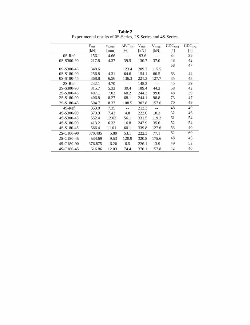
Table 2 Experimental results of 0S-Series, 2S-Series and 4S-Series.
Fmax uLmax ΔF/FRef Vmax Vf(exp) CDCtang. CDCavg.
[kN] [mm] [%] [kN] [kN] [°] [°]
0S-Ref 156.1 4.66 -- 93.6 -- 34 39
0S-S300-90 217.8 4.37 39.5 130.7 37.0 48 42
0S-S300-45 348.6
123.4 209.2 115.5 58 47
0S-S180-90 256.8 4.31 64.6 154.1 60.5 63 44
0S-S180-45 368.8 6.56 136.3 221.3 127.7 35 43
2S-Ref 242.1 4.70 -- 145.2 -- 45 39
2S-S300-90 315.7 5.32 30.4 189.4 44.2 58 42
2S-S300-45 407.1 7.03 68.2 244.3 99.0 48 39
2S-S180-90 406.8 8.27 68.1 244.1 98.8 73 47
2S-S180-45 504.7 8.37 108.5 302.8 157.6 70 49
4S-Ref 353.8 7.35 -- 212.3 -- 48 40
4S-S300-90 370.9 7.43 4.8 222.6 10.3 32 46
4S-S300-45 552.4 12.03 56.1 331.5 119.2 61 54
4S-S180-90 413.2 6.32 16.8 247.9 35.6 52 54
4S-S180-45 566.4 11.01 60.1 339.8 127.6 53 40
2S-C180-90 370.485 5.89 53.1 222.3 77.1 62 60
2S-C180-45 534.69 9.53 120.9 320.8 175.6 48 46
4S-C180-90 376.875 6.20 6.5 226.1 13.9 49 52
4S-C180-45 616.86 12.03 74.4 370.1 157.8 42 40

Table 3
Significant strains measured for 0S- 2S- 4S-Series.
Beam ID | SG Element ε Fmax
[%]
εmax
[%]
(uL/uLmax)
0S-S300-90 1 S1 0.06 0.08 (0.72)
6 S2 -- 0.29 (0.66)
0S-S300-45 3 S2 -- 0.92 (0.62)
8 S3 -- 0.87 (0.99)
0S-S180-90 1 S2 0.16 0.17 (1.03)
4 S3 0.59 1.06 (2.23)
0S-S180-45 3 S3 0.46 0.48 (1.03)
7 S4 -- 0.64 (0.89)
2S-Ref 1 St1 0.17 0.21 (1.49)
2S-S300-90 1 St1 0.14 0.19 (1.26)
2S-S300-45 3 St1 0.30 0.95 (1.07)
5 S1 0.16 0.73 (1.14)
6 S2 0.59 0.84 (0.63)
8 S2 0.30 0.92 (1.06)
2S-S180-90 3 St1 -- 1.00 (0.83)
2S-S180-45 2 St1 0.42 0.56 (1.13)
5 S2 0.30 0.31 (1.07)
8 S3 0.29 0.31 (1.11)
4S-Ref 1 St1 0.47 0.47 (1.00)
2 St2 0.75 0.86 (0.50)
4S-S300-90 6 S2 0.16 0.16 (1.00)
4S-S300-45 1 St1 0.25 0.31 (1.10)
3 St2 -- 0.89 (0.69)
4 S1 -- 0.38 (0.82)
6 S2 -- 0.91 (0.75)
8 S2 -- 0.90 (0.82)
4S-S180-90 2 St2 0.26 0.38 (1.06)
4 S2 0.04 0.05 (1.05)
7 S3 0.88 1.00 (1.02)
4S-S180-45 1 St1 0.41 0.48 (1.18)
3 St2 -- 0.96 (0.92)
5 S2 0.66 0.82 (1.20)
8 S3 0.26 0.27(1.20)
2S-C180-90 2 St1 -- 0.87 (0.79)
1* C2 0.40 0.46 (1.31)
4 C3 0.27 0.38 (0.82)
8 C4 0.67 0.67 (1.00)
2S-C180-45 2 C2 0.66 0.76 (1.20)
1* C2 0.46 0.56 (0.70)
4 C3 0.24 0.61 (0.63)
6 C4 -- 0.97 (0.92)
7 C4 -- 1.00 (0.83)
8 C4 0.86 0.86 (1.00)
4S-C180-90 4 C2 0.15 0.16 (1.05)
6 C3 0.13 0.15 (0.60)
4S-C180-45 3 St2 -- 0.79 (0.78)
5 C2 0.77 0.86 (1.18)
8 C3 0.62 0.89 (1.18)
2 C4 0.86 0.86 (1.00)

Table 4 Experimental results of previous experimental tests on beams strengthened with ETS technique.
Valerio et al 2009 [11] Angle
[θfw] Material
fcm,cube/fcm
[MPa]
ρsw
[%]
ρfw
[%]
ρsw+ ρfw
[%]
ΔF/FRef
[%]
Vf
[kN]
SLB P4d-2S8@d 90° S [55-60]a 0.00 0.09 0.09 18.0 53.2
SSB R3d-C6@0∙7d 90° C [55-60]a 0.00 0.24 0.24 97.0 22.9
SSB R3d-C6@0∙5d 90° C [55-60]a 0.00 0.34 0.34 114.0 27.0
SLB P4d-2C7∙5@d 90° C [55-60]a 0.00 0.08 0.08 14.6 43.2
SLB P4d-C7∙5@d 90° C [55-60]a 0.00 0.04 0.04 6.5 19.1
Chaallal et al 2011 [14]
S0-ETS 90° C 25.00b 0.00 0.64 0.64 112.40 99.50
Dalfré and Barros 2013 [15]
A.3 E300.90 90° S 30.78 b 0.00 0.17 0.17 47.7 31.2
A.4 E300.45 45° S 28.81 b 0.00 0.25 0.25 47.7 57.1
A.5 S300.90/E300.90 90° S 30.78 b 0.13 0.17 0.30 40.8 40.3
B.3 E300.90 90° S 30.78 b 0.00 0.11 0.11 17.5 21.3
B.4 E300.45 45° S 28.81 b 0.00 0.16 0.16 65.3 98.5
B.5 S300.90/E300.90 90° S 30.78 b 0.06 0.11 0.17 67.9 94.7 a fcm,cube. Average concrete cube compressive strength b fcm.. Average concrete cylindrical compressive strength

FIGURE CAPTIONS
Fig. 1. Tested beams: geometry, steel reinforcements applied in all beams (dimensions in mm).
Fig. 2. Reference Beams: (a) 2S-REF(stirrups ϕ6@300), (b) 4S-REF(stirrups ϕ6@180).
Fig. 3. Strengthening configurations of series: (a) 0S, (b) 2S; (c) 4S (dimensions in mm).
Fig. 4. Test set-up.
Fig. 5. Position of the strain gauges (dimensions in mm)
Fig. 6. Force vs deflection at the loaded section for (a) 0S-Series, (b) 2S-Series, (c) 4S-Series.
Fig. 7. Crack Patterns at Maximum Load.
Fig. 8. Load versus strains recorded in strain gauges applied in ETS bars and steel stirrups.
Fig. 9. Failure (a-b) loss of bond in ETS steel bars and CFRP roads, respectively, (c) scratching of the epoxy
adhesive (d) peeling-off of the CFRP road.
Fig. 10. Influence of the ρsw+ ρfw on the ETS effectiveness.
Fig. 11. ETS effectiveness (a) influence of ρsw and ρfw, (b) projection on the plane ΔF/FRef - ρfw.
Fig. 12. Comparison of shear strengthening efficiency between ETS, NSM and EBR techniques [48].

Fig. 1. Tested beams: geometry, steel reinforcements applied in all beams (dimensions in mm).

(a) (b)
Fig. 2. Reference Beams: (a) 2S-REF(stirrups ϕ6@300), (b) 4S-REF(stirrups ϕ6@180)

(a)
(b)
(c)
Fig. 3. Strengthening configurations of series: (a) 0S, (b) 2S; (c) 4S (dimensions in mm).

Fig. 4.Test set-up.

(a)
b)
(c)
Fig. 5. Position of the strain gauges (dimensions in mm).

(a)
(b)
(c)
Fig. 6. Force vs deflection at the loaded seciton for (a) 0S-Series, (b) 2S-Series, (c) 4S-Series.
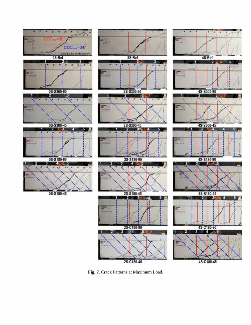
Fig. 7. Crack Patterns at Maximum Load.

(a) (b)
(c) (d)
(e) (f)
Fig. 8. Load versus strains recorded in strain gauges applied in ETS bars and steel stirrups.

Fig.9. Failure (a-b) loss of bond in ETS steel bars and CFRP roads, respectively, (c) scratching of the epoxy
adhesive (d) peeling-off of the CFRP road.

Fig. 10. Influence of the ρsw+ ρfw on the ETS effectiveness.
(a) (b)
Fig. 11. ETS effectiveness (a) influence of ρsw and ρfw, (b) projection on the plane ΔF/FRef - ρfw.

Fig. 12. Comparison of shear strengthening efficiency between ETS, NSM and EBR techniques [48].