Embed Size (px)
Citation preview

Embedded Systems
Programming and Architectures
Dr John Kalomiros
Assis. Professor
Department of Post Graduate studies in Communications and Informatics
Lecture No 7 : PIC 16F series Organization and programming

Essentials of a computer system and organization of memory access
a. Von-Neumann
b. Harvard

Medium PIC MCUs:
16F series
�Program memory (flash
EEPROM) 2K up to 8K
(13-bits Pr. Mem. addr bus)
�Instruction word: 14 bits
�Static RAM data memory
(File Registers 8-bit)=>
�8-bit data bus
�7 bits for direct addressing (128
bytes)+2 bits from STATUS
�Peripheral circuits: I/O Ports,
timers, Interrupts management
and serial interfaces

The programming model of 16F PIC MCUs
Memory matrix:
4 memory banks
each bank: 128 registers
(00h-7Fh)
Part of each bank is SFR
The rest is GPR
SFRs affect hardware functions
GPRs are given to the user
Total GPRs in 16F877: 368 bytes

The programming model of 16F PIC MCUsThe 16F877 STATUS Register
Important bits:
C: CARRY. It is set when addwf or subwf produce Carry
DC: Decimal Carry (useful in BCD arithmetic)
Z: Zero flag. It is set when arithmetic produces zero
RP0 and RP1: They form the 2 MS bits of the data memory address. They are the bank selection bits.

Instruction Set of the 16F series grouped by functi on

Data transfer commands
� movwf Reg
It copies the contents of Working
Register w to Register Reg
� movf Reg, w
It copies the content of register
Reg to the Working register w
� movlw k
It copies literal k to w. k here is a
literal number. It does not represent a memory location, like
Reg above.

� bsf REG, b
sets bit b of REG file register
i.e. bsf 03, 5 ;sets b5 of STATUS register
� bcf REG, b
clears bit b of REG file register
i.e. bcf 03, 5 ;clears b5 of STATUS register
Single bit manipulation
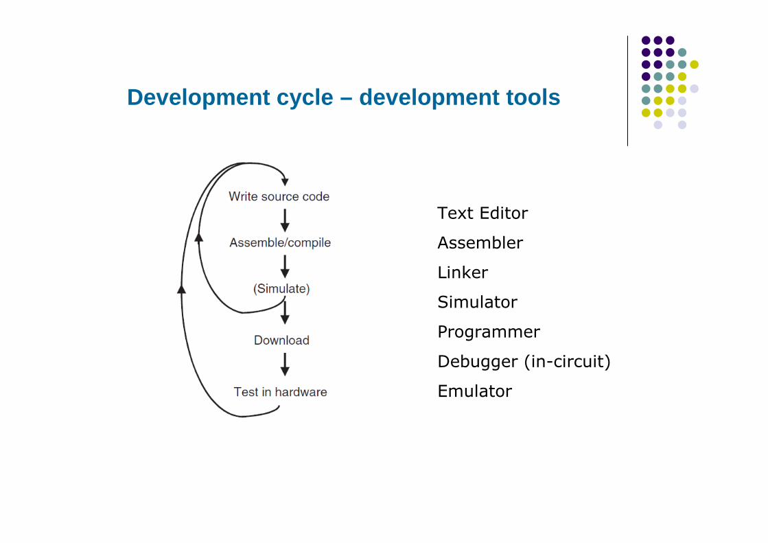
Development cycle – development tools
Text Editor
Assembler
Linker
Simulator
Programmer
Debugger (in-circuit)
Emulator

Microcontroller development boards
One or more MCUs
Standard peripherals for I/O, like LEDs and push buttons
A/D converters
Serial port
USB connectivity
Programming ability

Programmers
PICSTART Plus
Programmer by Microchip
It programs DIP MCUs before they are placed on-circuit

PICkit3 In-Circuit Programmer-debugger
Very cool tool!
Comparatively cheap (~50€)

A possible development circuit

Hardware connections: Understand supply and oscillator

Hardware connections: Understand input hardware

Hardware connections: Understand output hardware
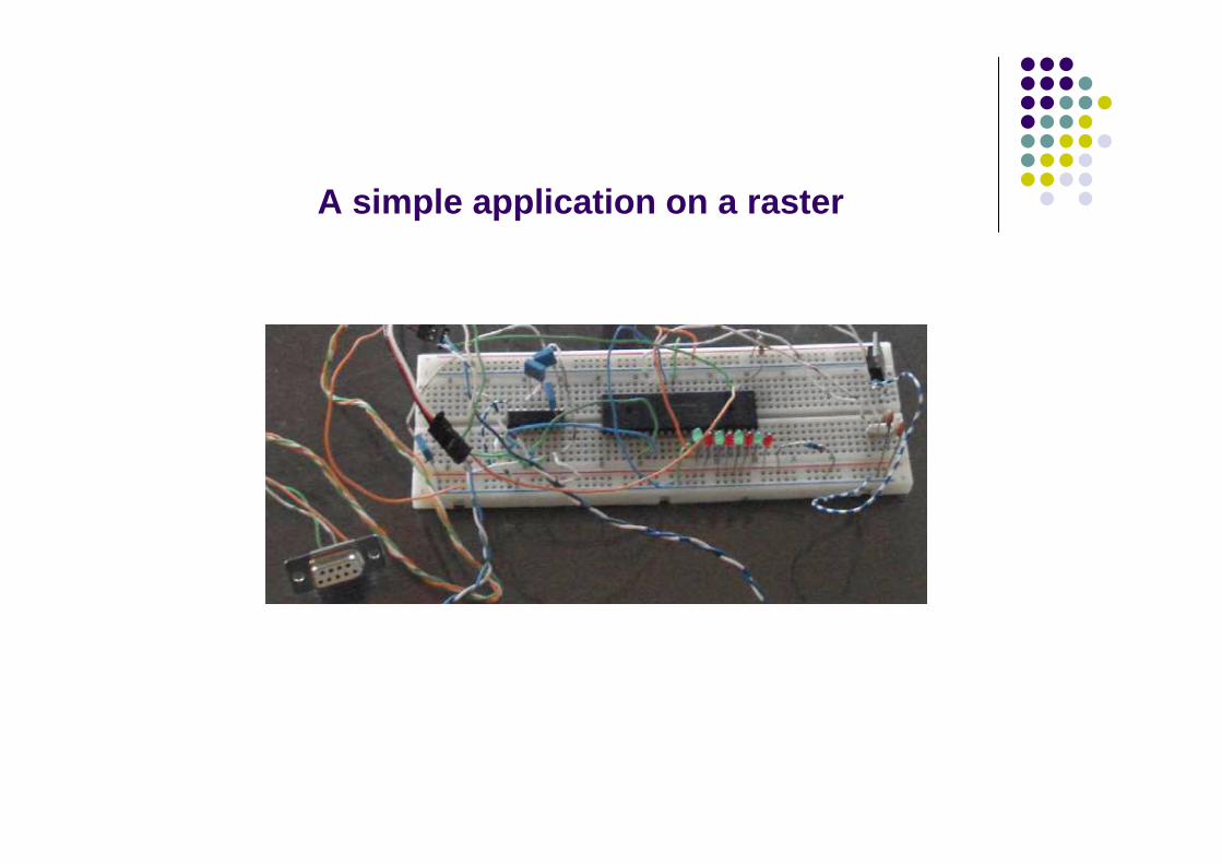
A simple application on a raster

MPLAB IDE: An Integrated tool for Software development

Example program for PIC 16F877� ; project_name: DIR \ test1� ;TITLE: This program reads PORTD and transfers data to PORT B� ;6.10.2012 by John
� ;#include "p16f877.inc" ; You may either include the .inc file OR declare nam es for the SFRs, as below
� ;Optionally set Configuration Word bits: WDT OFF, Pow er-up timer ON, code protect OFF, XT oscillator� list p=16F877 ;This is an optional directive� ;Specify names for SFRs OR include the “pxxxxx.inc” file� status equ 03� portd equ 08� trisd equ 08� portb equ 06� trisb equ 06
� Org 00 ;define the Reset vector� ;Initialization of peripherals� start bsf status, 5 ;select memory bank 1� movlw b'00000111'� movwf trisd ;the three first bits of portA are input� movlw 00� movwf trisb ;all pins of portB are output� bcf status, 5 ;return to bank0� ;main code starts here� main clrf portd� loop movf portd, w� movwf portb� goto loop� end

Example program for PIC 16F877 – with only necessary directives and definitions
� ; project_name: DIR \ test1� ;TITLE: this program reads PORTD and transfers data to PORTB� ;6.10.2012 by John
� #include "p16f877.inc"
� ; In this line we optionally set Configuration Word bits:� ; WDT OFF, Power-up timer ON, code protect OFF, XT oscillator, Low-Voltage Programming OFF
� Org 00 ;define the Reset vector� ;Initialization of peripherals� start bsf STATUS, RP0 ;select memory bank 1� movlw b'00000111'� movwf TRISD ;the three first bits of portA are input� movlw 00� movwf TRISB ;all pins of portB are output� bcf STATUS, RP0 ;return to bank0
� ;main code starts here� main clrf PORTB� loop movf PORTD, w� movwf PORTB� goto loop� end

Assembler directives and number representations

Assembler file structure and the role of the Linker
Simple assembler program development
Advanced assembler program development

Assembler program layout
� ;This program moves switch values � ;from PortD to the leds of PortB� ;project_name: test1, 6.10.2012
� list p=16F877 ;This is an optional directive�
� ;Specify SFRs (optionally)� status equ 03� portd equ 08� trisd equ 08� portb equ 06� trisb equ 06�
� Org 00 � ;Initialization of peripherals� start bsf status, 5
movlw b'00000111'� movwf trisd
movlw 00� movwf trisb
bcf status, 5� ;main code starts here� main clrf portd� loop movf portd, w� movwf portb� goto loop� end

The nature of the embedded application:The control loop

The nature of the embedded application:
The super-loop
Automobile super-loop controller for real-time operation

Flow diagrams and control-loops
Endless loop
The fridge control-loop
(project No 1)

Bit testing and flow control
� btfss Reg, b i.e. btfss STATUS, Z;test bit b of Reg and skip next instruction if bit set
� btfsc Reg, b i.e. btfsc PORTD, 0;test bit b of Reg and skip next instruction if bit 0
� incfsz Reg, decfsz Reg
� goto label or goto addr i.e. goto main or goto 08
� movwf PCL, addwf PCL

Test port pins and branch (example)
#include "p16F877.inc"
;Initialization
Org 0 ;Start from prog memory address 0
bsf STATUS, RP0 ;Change to bank1
movlw b'00000000' ;Make all pins of portB outputs
movwf TRISB
movlw b'11111111' ;Make all pins of portD inputs
movwf TRISD
bcf STATUS, RP0 ;Return to bank0
main movlw b'01010101' ;Output to portB
movwf PORTB
btfss PORTD, 0 ;Wait until pin0 of portD receives 1
goto $-1 ;Go to previous instruction
movlw b'10101010' ;change output combination to portB
movwf PORTB
btfss PORTD, 1 ;Wait until pin1 of portD receives 1
goto $-1
goto main
end

Arithmetic operations (unsigned, 8-bit)
� addlw number w=number+w addlw 05
� sublw number w=number-w sublw 2A
� addwf Reg, w or 0 w=Reg+w addwf 21h,0
� addwf Reg, 1 Reg=Reg+w
� subwf Reg, w or 0 w=Reg-w subwf 20h,w
� subwf Reg, 1 Reg=Reg-w

Example:Write a program to sum all integers in interval [start value, max value]
START
Initialize element
(with start value)
Add element to sum
Is element=max?
No
Yes
Produce next
element
Endless
wait
Initialize sum
(with zero)

;This program adds up all integers in interval [start, max];For example from 1 to 10 [1, 10]
;The sum is stored in memory location 21h;8.10.2012 by John Kalomiros
#include "p16f877.inc"
element equ 20h ;define address to store current added elementsum equ 21h ;define address for sumstart equ d'1' ;start int value (decimal)max equ d'10' ;max int value (decimal)
Org 00;Initialize memory
movlw 00
movwf sum ;initialize sum
movlw start
movwf element ;load first element
;main code starts here
main movf element,w
addwf sum,1 ;add current element to sum
movf element, w
sublw max ;compare element with stop value
btfsc STATUS, Z ;if element exceeds max value, then stop
loop goto loop ;endless loop - wait here
incf element ;otherwise produce next element
goto main ;continue loop
end

Subroutines
Subroutines: useful pieces of reusable code that can be repeatedly called from any program location. Always in pairs of Call…return see also: retlw xx

Delay subroutine (1ms)
� ;With crystal XT and fosc=4MHz, instruction cycle is 1 µs
� ;branch instructions (call, goto) take 2µs
� delay
� movlw 0F9 ;load decimal 249
� nop ;first two instructions take 2µs
� micro4
� addlw 0FF ;add -1 in 2's complement
� btfss STATUS,Z ;no skip: 1µs. With skip: 2µs
� goto micro4 ;2µs
� return ;2µs
Loop micro4 takes 4µs x 249 iterations=996µs
First two instructions of “delay” take 2µs
Call delay instruction takes 2 µs.
Total time from call delay to return =1000µs=1ms

Internal Timing issues
If external frequency is fosc, then Tosc=1/ fosc
For example with fosc=4MHz, Tosc=0,25µs
Execution of one instruction takes 4 cycles of the external clock:
fetch, decode, execute and store = 1 instruction cycle
In other words: Duration of 1 instruction cycle = 4*Tosc
For example with fosc=4MHz, 1 instruction takes 1µs

Timing issues (continued)
Duration of a group of instructions =Number of instructions x duration of instruction cycle
Remember:
Branch instructions like goto, call, take 2 instruction cycles
btfss, btfsc, decfsc, take 2 cycles only when skip is performed

delay_msmovwf msec
loop movlw 0F8 ;decimal 248call micro4 ;248x4+2=994µsnopnopdecfsz msec, fgoto loopreturn
micro4addlw 0FFbtfss STATUS, Z goto micro4return
#include "p16f877.inc"
msec equ 20h
;don’t forget to initialize!
clrf PORTB
main movlw d'100'
call delay_ms
comf PORTB
end
A delay subroutine for up to 255 msec
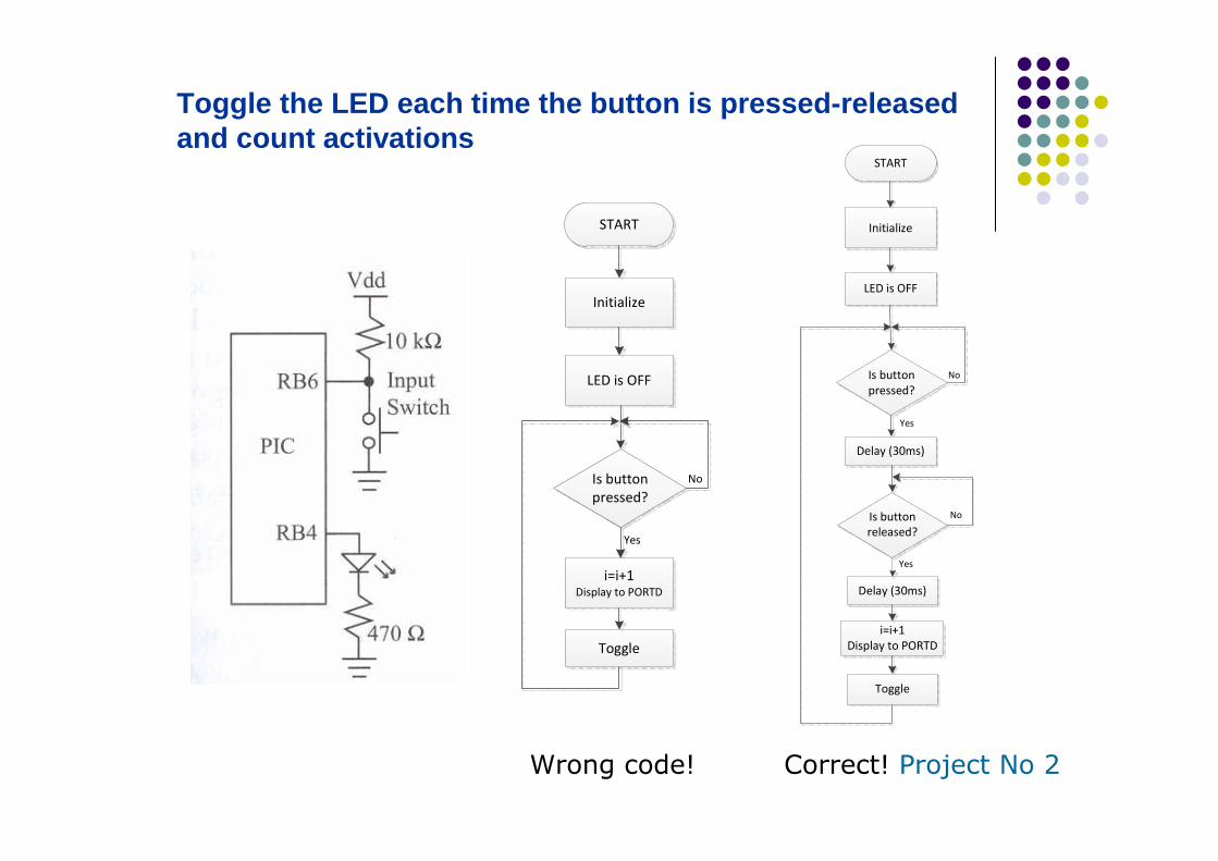
Toggle the LED each time the button is pressed-relea sed and count activations
START
Initialize
LED is OFF
Is button
pressed?
Toggle
No
Yes
i=i+1Display to PORTD
Wrong code! Correct! Project No 2
START
Initialize
LED is OFF
Is button
pressed?
Toggle
No
Yes
Delay (30ms)
Is button
released?
Delay (30ms)
i=i+1
Display to PORTD
No
Yes

;This program adds up all elements of a matrix ;The matrix is held in program memory as a LUT;For example matrix=[2, 10, 20, 3, 8], all decimal values;The sum is projected on the LEDs of PORTB ;9.10.2012 by John Kalomiros
#include "p16f877.inc"
pointer equ 20h ;define address of current pointer value
sum equ 21h ;define address for sum
size equ d'5' ;matrix size (decimal)
Org 00
;Initialize ports
bsf STATUS, RP0
movlw b'00000000'
movwf TRISB
bcf STATUS, RP0
;Initialize memory
movlw 00
movwf sum ;initialize sum
clrf pointer ;initialize pointer(with zero)
clrf PORTB
Access matrix elements in LUT:example: sum up elements in a matrix (1/2)

example: sum up elements in a matrix (continued 2/2 ) Main code and LUT subroutine (with retlw xx)
;main code starts here
main movf pointer,w
call table
addwf sum,1 ;add new element to sum
incf pointer,1 ;increment pointer
movf pointer, w
sublw size ;compare new pointer with size value
btfss STATUS, Z ;if pointer exceeds size, then skip
goto main
movf sum, w
movwf PORTB ;show result on the LEDs of PORTB
loop goto loop
;This subroutine holds LookUp Table
table addwf PCL
retlw d'02‘ ;returns with xx value in WREG
retlw d'10'
retlw d'20'
retlw d'03'
retlw d'08'
end

Find the minimum among N elements in a matrix
First, put values in RAM memory:
Start with the maximum possible min value: min=0xFF
Then, scan all memory locations using FSR and INDF registers
and compare each value with the previous min value.
Update min value at each step.

Find the minimum among N elements in a matrix
Project No 3
START
Load FSR with start
memory address
Put values into
memory
Load min with 0xFF
Find difference
min-INDF
Is Carry=1?
(min<INDF?)
Update min
min INDF min old min
Yes No
Increment FSR
Is current FSR value=
end memory address?
Yes
NoEndless
wait

Find the minimum among N elements in a matrix
;write code to put values into memory
;main routine
find_min clrf PORTB
movlw 0xFFmovwf min ;put in min the maximum possible value
movlw startf
movwf FSR ;start memory location in FSR
loop2 movf INDF,w ;access memory location in FSR
subwf min,w ;compare current memory value with min (min-w)
btfss STATUS,C ;if Carry=1 then result is negative (min<INDF)
movf min,w ;in which case min is minimum
btfsc STATUS,C ;if Carry=0 then sub result is positive (INDF<min)
movf INDF,w ;in which case INDF is minimum
movwf min ;update min
movf FSR,w
sublw endf ;check if current memory is last
btfsc STATUS,Z
goto label
incf FSR,1 ;access next memory location
goto loop2 ;repeat comparison
label movf min,w
movwf PORTB ;project the minimum value on PORTB
endless goto endless
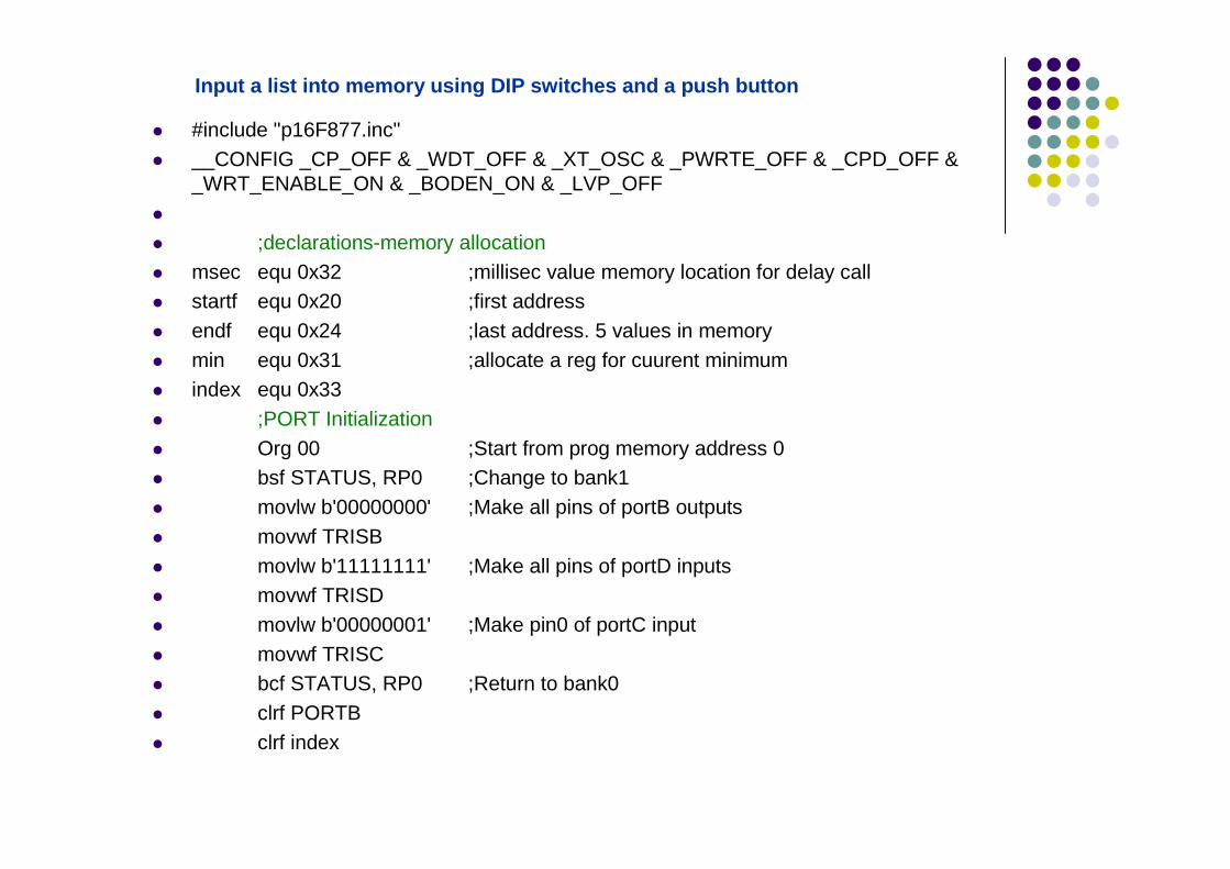
Input a list into memory using DIP switches and a p ush button
� #include "p16F877.inc"� __CONFIG _CP_OFF & _WDT_OFF & _XT_OSC & _PWRTE_OFF & _CPD_OFF &
_WRT_ENABLE_ON & _BODEN_ON & _LVP_OFF�
� ;declarations-memory allocation� msec equ 0x32 ;millisec value memory location for delay call� startf equ 0x20 ;first address� endf equ 0x24 ;last address. 5 values in memory� min equ 0x31 ;allocate a reg for cuurent minimum� index equ 0x33� ;PORT Initialization� Org 00 ;Start from prog memory address 0� bsf STATUS, RP0 ;Change to bank1� movlw b'00000000' ;Make all pins of portB outputs� movwf TRISB� movlw b'11111111' ;Make all pins of portD inputs� movwf TRISD� movlw b'00000001' ;Make pin0 of portC input� movwf TRISC� bcf STATUS, RP0 ;Return to bank0� clrf PORTB� clrf index

Input a list into memory using DIP switches (contin ued)
;part A: Read Input Data from PORTD and put the values in memory
movlw startf
movwf FSR
read btfss PORTC, 0 ;pin C0 p-b pressed?
goto $-1
movlw d'50' ;50 ms delay
call delay_ms ;delay to debounce
btfsc PORTC, 0 ;pin C0 p-b released?
goto $-1
movlw d'50'
call delay_ms ;delay to debounce
movf PORTD,w
movwf INDF ;store datum. Find memory location address in reg FSR
incf index,1
movf index,w
movwf PORTB ;project index on PORTB
movf FSR,w
sublw endf ;Is this the last input value?
btfsc STATUS, Z
goto find_min
incf FSR,1 ;access next input value
goto read ;read next value
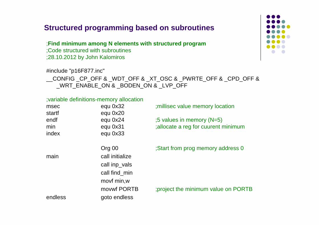
Structured programming based on subroutines
;Find minimum among N elements with structured progra m;Code structured with subroutines;28.10.2012 by John Kalomiros
#include "p16F877.inc"__CONFIG _CP_OFF & _WDT_OFF & _XT_OSC & _PWRTE_OFF & _CPD_OFF &
_WRT_ENABLE_ON & _BODEN_ON & _LVP_OFF
;variable definitions-memory allocationmsec equ 0x32 ;millisec value memory locationstartf equ 0x20endf equ 0x24 ;5 values in memory (N=5)min equ 0x31 ;allocate a reg for cuurent minimumindex equ 0x33
Org 00 ;Start from prog memory address 0main call initialize
call inp_valscall find_minmovf min,wmovwf PORTB ;project the minimum value on PORTB
endless goto endless

CONFIGURATION BITS
These are part of the MCU’s internal memory. They can only be changed during programming (never
during run-time). They set the mode of function of certain internal units, like the oscillator, the WDT,
programming mode, etc.
You may set them in code using the declaration __CONFIG:
__CONFIG _CP_OFF & _WDT_OFF & _XT_OSC & _PWRTE_OFF & _CPD_OFF &
_WRT_ENABLE_ON & _BODEN_ON & _LVP_OFF
OR you may set them in MPLAB selecting Configure=>Configuration Bits in the
main menu
BEWARE: if you omit to set the configuration bits you are bound to run into potentially
serious problems
Required reading:
Designing Embedded Systems with PIC microcontrollersby Tim Wilmshurst, chapters 4 and 5.
Embedded Systems design: A Unified Hardware-software approachby Frank Vahid and Tony Givargis, chapter 1.