Embed Size (px)
Citation preview

8/9/2016
1
ĐẠI HỌC QUỐC GIA TP.HỒ CHÍ MINHTRƯỜNG ĐẠI HỌC BÁCH KHOA
KHOA ĐIỆN-ĐIỆN TỬ BỘ MÔN KỸ THUẬT ĐIỆN TỬ
11
Embedded System Design
5. Software development for an embedded system
1. Software diagram2. C Programming for PIC3. Timer and interrupt
Bộ môn Kỹ Thuật Điện Tử - ĐHBK
1. Software diagram
• Software diagram is a diagram help software developers and program managers to interpret software application relationships, actions, and processes.
– Software architecture diagram: describes the high level structure of a software system
– Program flowchart: demonstrates how a program works within a system
– Data flow diagram: illustrates the flow of information in a process
– State machine diagram: presents decision flows of a state machine
2Chapter 5

8/9/2016
2
Bộ môn Kỹ Thuật Điện Tử - ĐHBK
1. Software diagram
• Draw a software diagram:
– Use a rectangle for a process
– Use a rounded rectangle for a terminator
– Use a diamond shape for a decision
– Use a parallelogram for data
– Use a rectangle with two vertical lines for predefine process
3
Y
N
process terminator decision data predefine process
Chapter 5
Bộ môn Kỹ Thuật Điện Tử - ĐHBK
1. Software diagram• Example for software architecture diagram
– Show the connections between hardware and software
– Show the connections with other systems
– Show the interface with users
4
Examples
Chapter 5

8/9/2016
3
Bộ môn Kỹ Thuật Điện Tử - ĐHBK
1. Software diagram• Software block diagram ‐ Example
5
State machine diagramProgram flowchart
Chapter 5
Bộ môn Kỹ Thuật Điện Tử - ĐHBK
1. Software diagram• Data flow diagram(DFD)
6Chapter 5

8/9/2016
4
Bộ môn Kỹ Thuật Điện Tử - ĐHBK
Group discussion • Discus about below software diagram:
7
Init LCD
Oven control system
START
Read temperature T
T>T_đặt?Turn OFF heater
Turn ON heater
•Decision block must have YES/NO branches•A process block must have 1 input and 1 output
Chapter 5
Bộ môn Kỹ Thuật Điện Tử - ĐHBK
Team work
• Draw a software diagram for your class project
8Chapter 5

8/9/2016
5
Bộ môn Kỹ Thuật Điện Tử - ĐHBK
2. C programming for PIC
• Reference
– Martin Bates, “Programming 8‐bit PIC Microcontrollers in C”, Newnes, 2008
• Many C compilers for PIC:
– MikroC (www.mikroe.com)
– PICC18 (www.htsoft.com)
– MPLAB C18, C30 (www.microchip.com)
– CCS C (www.microchipc.com/reviews/CCS_C/)
9Chapter 5
Bộ môn Kỹ Thuật Điện Tử - ĐHBK
Outline
2.1 PIC16 C Getting Started
● Simple program and test circuit
● Variables, looping, and decisions
● SIREN program
2.2 PIC16 C Program Basics
● Variables
● Looping
● Decisions
2.3 PIC16 C Data Operations
● Variable types
● Floating point numbers
● Characters
● Assignment operators
2.4 PIC16 C Sequence Control●While loops● Break, continue, goto● If, else, switch
2.5 PIC16 C Functions and Structure● Program structure● Functions, arguments● Global and local variables
2.6 PIC16 C Input and Output● RS232 serial data● Serial LCD● Calculator and keypad
2.7 PIC16 C More Data Types● Arrays and strings● Pointers and indirect addressing● Enumeration
10Chapter 5

8/9/2016
6
Bộ môn Kỹ Thuật Điện Tử - ĐHBK
2.1 PIC16 C Getting Started
Microcontroller programs contain three main features:● Sequences of instructions● Conditional repetition of sequences● Selection of alternative sequences
Listing 2.1 A program to output a binary code
/* Source code file: OUTNUM.C Author, date, version: MPB 11-7-07 V1.0 Program function: Outputs an 8-bit codeSimulation circuit: OUTBYTE.DSN
*******************************************************/#include "16F877A.h" // MCU select
void main() // Main block{
output_D(255); // Switch on outputs}
11Chapter 5
Bộ môn Kỹ Thuật Điện Tử - ĐHBK
Figure 2.1 MPLAB IDE Screenshot
12Chapter 5

8/9/2016
7
Bộ môn Kỹ Thuật Điện Tử - ĐHBK
Figure 2.2 ISIS dialogue to attach program
13Chapter 5
Bộ môn Kỹ Thuật Điện Tử - ĐHBK
Setup IO Ports• Port modes
– #use fast_io(port): leaves the state of the port the same unless re‐configured
– #use fixed_io(port_outputs=pin, pin): permanently sets up the data direction register for the port
– #use standard_io(port): default for configuring the port every time it’s used
• Set directions– set_tris_a(value);
– value = get_tris_a();
• Read / write IO ports– value = input_A(); // read value from a port
– value = input(PIN_B0); // read value from a pin
– output_A(value); // write value to a port
– output_high(pin); //set an output to logic 1
– output_low(pin); //set an output to logic 0
– Output_bit(pin, value); // Outputs the specified value to the specified I/O pin14Chapter 5

8/9/2016
8
Bộ môn Kỹ Thuật Điện Tử - ĐHBK
PIC16 C Program Basics● Variables● Looping● Decisions
•The purpose of an embedded program is • to read in data or control inputs, • to process them and operate the outputs as required.
•The program for processing the data usually contains repetitive loops and conditional branching, which depends on an input or calculated value.
2.2 PIC16 C Program Basics
15Chapter 5
Bộ môn Kỹ Thuật Điện Tử - ĐHBK
Variables
• Variables:– is a label attached to the memory location where the variable value is
stored.
– automatically assigned to the next available location or locations (many variable types need more than 1 byte of memory).
– must be declared at the start of the program block, so that the compiler can allocate a corresponding set of locations.
– Only alphanumeric characters (a–z, A–Z, 0–9) can be used for variable names
• Variable values– in decimal by default
– in hexadecimal with the prefix 0x, for example, 0xFF
• By default, the CCS compiler is not case sensitive,
16Chapter 5

8/9/2016
9
Bộ môn Kỹ Thuật Điện Tử - ĐHBK
Listing 2.2 Variables
/* Source code file: VARI.C Author, date, version: MPB 11-7-07 V1.0 Program function: Outputs an 8-bit variableSimulation circuit: OUTBYTE.DSN
*******************************************************/
#include "16F877A.h"
void main(){
int x; // Declare variable and type
x=99; // Assign variable valueoutput_D(x); // Display the value in binary
}
17Chapter 5
Bộ môn Kỹ Thuật Điện Tử - ĐHBK
Looping• Most real‐time applications need to execute continuously until the
processor is turned off or reset.
• In C this can be implemented as a “ while ” loop, as in Listing 2.3 .
/* Source code file: ENDLESS.C Author, date, version: MPB 11-7-07 V1.0 Program function: Outputs variable countSimulation circuit: OUTBYTE.DSN
*******************************************************/#include "16F877A.h”void main(){
int x; // Declare variable
while(1) // Loop endlessly{ output_D(x); // Display value
x++; // Increment value}
}
18Chapter 5

8/9/2016
10
Bộ môn Kỹ Thuật Điện Tử - ĐHBK
Decision Making
•The effect of the program is to switch on the output if the input is high. •The switch needs to be closed before running to see this effect. •The LED cannot be switched off again until the program is restarted.
• The simplest way to illustrate basic decision making is to change an output depending on the state of an input.
• Figure 2.4 show test circuit with input switch
19Chapter 5
Bộ môn Kỹ Thuật Điện Tử - ĐHBK
Listing 2.4 IF statement
/* Source code file: IFIN.C Author, date, version: MPB 11-7-07 V1.0 Program function: Tests an inputSimulation circuit: INBIT.DSN
*******************************************************/#include "16F877A.h"
void main(){
int x; // Declare test var.output_D(0); // Clear all outputs
while(1) // Loop always{ x = input(PIN_C0); // Get inputif(x==1)output_high(PIN_D0); // Change out
}}
20Chapter 5

8/9/2016
11
Bộ môn Kỹ Thuật Điện Tử - ĐHBK
Loop Control• The program can be simplified by combining the input function
with the condition statement as follows:– if (input(PIN_C0)) output_high(PIN_D0);
• The conditional sequence can also be selected by a while condition.
• In Program WHILOOP.C ( Listing 2.5 )– the input is tested in the loop condition statement and the output flashed on
and off while the switch is open (input high).
– If the switch is closed, the flash loop is not executed and the LED is switched off.
21Chapter 5
Bộ môn Kỹ Thuật Điện Tử - ĐHBK
Listing 2.5 Conditional loop
/* Source code file: WHILOOP.C Author, date, version: MPB 11-7-07 V1.0 Program function: Input controls output loopSimulation circuit: INBIT.DSN
*******************************************************/#include "16F877A.h"#use delay (clock=1000000) // MCU clock = 1MHzvoid main(){
while(1){while(input(PIN_C0)); // Repeat while switch open{ output_high(PIN_D0);
delay_ms(300); // Delay 0.3soutput_low(PIN_D0);delay_ms(500); // Delay 0.5s
}output_low(PIN_D0); // Switch off LED
}}
22Chapter 5

8/9/2016
12
Bộ môn Kỹ Thuật Điện Tử - ĐHBK
FOR Loop
• The WHILE loop repeats until some external event or internally modified value satisfies the test condition.
• In other cases, we need a loop to repeat a fixed number of times.
• The FOR loop uses a loop control variable, which is set to an initial value and modified for each iteration while a defined condition is true.
• In the demo program FORLOOP.C ( Listing 2.6 ), the loop control parameters are given within the parentheses that follow the for keyword.
23Chapter 5
Bộ môn Kỹ Thuật Điện Tử - ĐHBK
FOR Loop
24Chapter 5

8/9/2016
13
Bộ môn Kỹ Thuật Điện Tử - ĐHBK
SIREN Program
• A program combining some of these basic features is shown in SIREN.C ( Listing 2.7 ).
• This program outputs to a sounder rather than an LED, operating at a higher frequency.
• The output is generated when the switch is closed (input C0 low).
• The delay picks up the incrementing value of “ step” giving a longer pulse each time the for loop is executed.
• This causes a burst of 255 pulses of increasing length (reducing frequency), repeating while the input is on.
• Note that 255 is the maximum value allowed for “ step, ” as it is an 8‐bit variable.
25Chapter 5
Bộ môn Kỹ Thuật Điện Tử - ĐHBK
Listing 2.7 Siren Program
/* Source code file: SIREN.C Author, date, version: MPB 11-7-07 V1.0 Program function: Outputs a siren soundSimulation circuit: INBIT.DSN
*******************************************************/#include "16F877A.h"#use delay (clock=1000000)void main(){int step;while(1){while(!input(PIN_C0)) // loop while switch ON{
for(step=0;step<255;step++) // Loop control{
output_high(PIN_D0); // Sound sequencedelay_us(step);output_low(PIN_D0);delay_us(step);
}}
}}
26Chapter 5

8/9/2016
14
Bộ môn Kỹ Thuật Điện Tử - ĐHBK
Listing 2.8 Program Blank
/* Source Code Filename: Author/Date/Version: Program Description:Hardware/simulation:
************************************************************/
#include "16F877A.h" // Specify PIC MCU#use // Include library routines
void main() // Start main block{
int // Declare global variables
while(1) // Start control loop{
// Program statements}
} // End main block
27Chapter 5
Bộ môn Kỹ Thuật Điện Tử - ĐHBK
Blank Program
• A blank program is shown in Listing 2.8 , which could be used as a general template.
• We should try to be consistent in the header comment information, so a standard comment block is suggested.
• Compiler directives are preceded by hash marks and placed before the main block.
• Other initialization statements should precede the start of the main control loop. Inclusion of the unconditional loop option while(1) assumes that the system will run continuously until reset.
28Chapter 5

8/9/2016
15
Bộ môn Kỹ Thuật Điện Tử - ĐHBK
Table 2.1 A basic set of CCS C components
Compiler Directives#include source files Include another source code or header file#use functions(parameters) Include library functions
C Blocksmain(condition) {statements } Main program blockwhile(condition) {statements } Conditional loopif(condition) {statements } Conditional sequencefor(condition) {statements } Preset loop
C Functionsdelay_ms(nnn) Delay in millisecondsdelay_us(nnn) Delay in microsecondsoutput_x(n) Output 8-bit code at Port Xoutput_high(PIN_nn) Set output bit highoutput_low(PIN_nn) Set output bit lowinput(PIN_nn) Get input
29Chapter 5
Bộ môn Kỹ Thuật Điện Tử - ĐHBK
● Variable types● Floating point numbers● Characters● Assignment operators
A main function of any computer program is to carry out calculations and other forms of data processing. Data structures are made up of different types of numerical and character variables, and a range of arithmetical and logical operations are needed.
Microcontroller programs do not generally need to process large volumes of data, but processing speed is often important.
2.3 PIC16 C Data Operations
30Chapter 5

8/9/2016
16
Bộ môn Kỹ Thuật Điện Tử - ĐHBK
Table 2.1 Integer Variables
Name Type Min Max
int1 1 bit 0 1
unsigned int8 8 bits 0 255
signed int8 8 bits -127 +127
unsigned int16 16 bits 0 65525
signed int16 16 bits -32767 +32767
unsigned int32 32 bits 0 4294967295
signed int32 32 bits -2147483647 +2147483647
31Chapter 5
Bộ môn Kỹ Thuật Điện Tử - ĐHBK
Table 2.2 Microchip/CCS Floating Point Number Format
Exponent Sign Mantissa
xxxx xxxx x xxx xxxx xxxx xxxx xxxx xxxx
8 bits 1 23 bits
Table 2.4 Example of 32-bit floating point number conversion
Mantissa: 101 0010 0000 0000 0000 0000
Exponent: 1000 0011
Sign: 1 = negative number
FP number: 1000 0011 1101 0010 0000 0000 0000 0000
Floating Point Number Format
Chapter 5 32

8/9/2016
17
Bộ môn Kỹ Thuật Điện Tử - ĐHBK
Figure 2.5 Variable Types
Chapter 5 33
Bộ môn Kỹ Thuật Điện Tử - ĐHBK
Low Bits
High Bits
0010 0011 0100 0101 0110 0111
0000 Space 0 @ P ` p
0001 ! 1 A Q a q
0010 " 2 B R b r
0011 # 3 C S c s
0100 $ 4 D T d t
0101 % 5 E U e u
0110 & 6 F V f v
0111 ' 7 G W g w
1000 ( 8 H X h x
1001 ) 9 I Y i y
1010 * : J Z j z
1011 + ; K [ k {
1100 , < L \ l |
1101 - = M ] m }
1110 . > N ^ n ~
1111 / ? O _ o Del
Table 2.5 ASCII Codes
Chapter 5 34

8/9/2016
18
Table 2.6 Arithmetic and Logical Operations
OPERATION OPERATOR DESCRIPTION SOURCE CODE EXAMPLE RESULT
Single operandIncrement ++ Add one
to integerresult = num1++; 0000 0000 0000
0001
Decrement -- Subtract onefrom integer
result = num1--; 1111 1111 1111 1110
Complement ~ Invert all bitsof integer
result = ~num1; 0000 0000 1111 1111
Arithmetic Operation
Add + Integer orFloat
result = num1 + num2;
0000 1010+ 0000 0011
0000 1101
Subtract - Integer orFloat
result = num1 - num2;
0000 1010- 0000 0011
0000 0111
Multiply * Integer orFloat
result = num1 * num2;
0000 1010* 0000 0011
0001 1110
Divide / Integer orFloat
result = num1 / num2;
0000 1100/ 0000 0011
0000 0100
Logical OperationLogical AND & Integer
Bitwiseresult = num1 & num2;
1001 0011& 0111 0001
0001 0001
Logical OR | IntegerBitwise
result = num1 | num2;
1001 0011| 0111 0001
1111 0011
Exclusive OR ^ IntegerBitwise
result = num1 ^ num2;
1001 0011^ 0111 0001
1110 0010
Chapter 5 35
Bộ môn Kỹ Thuật Điện Tử - ĐHBK
Figure 2.6 Variable Operations
Chapter 5 36

8/9/2016
19
Bộ môn Kỹ Thuật Điện Tử - ĐHBK
Operation Symbol EXAMPLE
Equal to == if(a == 0) b=b+5;
Not equal to != if(a != 1) b=b+4;
Greater than > if(a > 2) b=b+3;
Less than < if(a < 3) b=b+2;
Greater than or equal to >= if(a >= 4) b=b+1;
Less than or equal to <= if(a <= 5) b=b+0;
Table 2.7:Conditional Operators
Chapter 5 37
Bộ môn Kỹ Thuật Điện Tử - ĐHBK
2.4 PIC16 C Sequence Control●While loops
● Break, continue, goto
● If, else, switch
• Conditional branching operations are a basic feature of any program.
• These must be properly organized so that the program structure is maintained and confusion avoided.
• The program then is easy to understand and more readily modified and upgraded.
Chapter 5 38

8/9/2016
20
Bộ môn Kỹ Thuật Điện Tử - ĐHBK
While Loops
The basic while(condition) provides a logical test at the start of a loop, and the statement block is executed only if the condition is true. It may, however, be desirable that the loop block be executed at least once, particularly if the test condition is affected within the loop. This option is provided by the do..while(condition) syntax. The difference between these alternatives is illustrated in Figure 2.7 . The WHILE test occurs before the block and the DO WHILE after.
The program DOWHILE shown in Listing 2.9 includes the same block of statements contained within both types of loop. The WHILE block is not executed because the loop control variable has been set to 0 and is never modified. By contrast, ‘ count ’ is incremented within the DO WHILE loop before being tested, and the loop therefore is executed.
Chapter 5 39
Bộ môn Kỹ Thuật Điện Tử - ĐHBK
Condition True?
StatementBlock Conditio
n True?
StatementBlock
(a) While loop (b) Do..While loop
Figure 2.3.1 Comparison of While and Do..While Loop
Chapter 5 40

8/9/2016
21
Bộ môn Kỹ Thuật Điện Tử - ĐHBK
// DOWHILE.C// Comparison of WHILE and DO WHILE loops #include "16F877A.H”main(){int outbyte1=0;
int outbyte2=0;int count;count=0; // This loop is not
while (count!=0) // executed{ output_C(outbyte1);
outbyte1++;count--;}count=0; // This loop isdo // executed{ output_C(outbyte2);outbyte2++;count--;} while (count!=0);while(1){};
}
Listing 2.9 DOWHILE.C contains both types of ‘while’ loop
Chapter 5 41
Bộ môn Kỹ Thuật Điện Tử - ĐHBK
Break, Continue, and Goto
It may sometimes be necessary to break the execution of a loop or block in the middle of its sequence ( Figure 2.8 ). The block must be exited in an orderly way, and it is useful to have the option of restarting the block (continue) or proceeding to the next one (break).
Occasionally, an unconditional jump may be needed, but this should be regarded as a last resort, as it tends to threaten the program stability. It is achieved by assigning a label to the jump destination and executing a goto..label.
The use of these control statements is illustrated in Listing 2.10 . The events that trigger break and continue are asynchronous (independent of the program timing) inputs from external switches, which allows the counting loop to be quit or restarted at any time.
Chapter 5 42

8/9/2016
22
Bộ môn Kỹ Thuật Điện Tử - ĐHBK
label
StatementBlock
ContinueGoto
Break
Figure 2.8 Break, continue and goto
Chapter 5 43
Bộ môn Kỹ Thuật Điện Tử - ĐHBK
// CONTINUE.C// Continue, break and goto jumps #include "16F877A.H"#use delay(clock=4000000)main(){
int outbyte;again: outbyte=0; // Goto destinationwhile(1){
output_C(outbyte); // Loop operationdelay_ms(10);outbyte++; if (!input(PIN_D0)) continue; // Restart loopif (!input(PIN_D1)) break; // Terminate loopdelay_ms(100);if (outbyte==100) goto again; // Unconditional jump
}}
Listing 2.10 Continue, Break & Goto
Chapter 5 44

8/9/2016
23
Bộ môn Kỹ Thuật Điện Tử - ĐHBK
If block
ConditionTrue?
YES
NO
ConditionTrue?
If block
Elseblock
YES NO
Figure 2.9 Comparison of If and If..Else
Chapter 5 45
Bộ môn Kỹ Thuật Điện Tử - ĐHBK
Test Variable
Value = 3? Procedure 3YES
NO
Value = n? Procedure nYES
NO
Default Procedure
Value = 2? Procedure 2YES
NO
Value = 1? Procedure 1YES
NO
Figure 2.10 Switch..case branching structure
Chapter 5 46

8/9/2016
24
Listing 2.11 Comparison of Switch and If..Else control// SWITCH.C// Switch and if..else sequence control// Same result from both sequences#include "16F877A.h”void main(){
int8 inbits;while(1){
inbits = input_D(); // Read input byte// Switch..case option................................................
switch(inbits) // Test input byte{
case 1: output_C(1); // Input = 0x01, output = 0x01break; // Quit block
case 2: output_C(3); // Input = 0x02, output = 0x03break; // Quit block
case 3: output_C(7); // Input = 0x03, output = 0x07break; // Quit block
default:output_C(0); // If none of these, output = 0x00}
// If..else option....................................................if (input(PIN_D0)) output_C(1); // Input RD0 highif (input(PIN_D1)) output_C(2); // Input RD1 highif (input(PIN_D0) && input(PIN_D1)) output_C(7); // Both high else output_C(0); // If none of these, output = 0x00
}} Chapter 5 47
Bộ môn Kỹ Thuật Điện Tử - ĐHBK
Class Assignments1. Write a C function to convert a BCD code to a
common‐anode 7‐segment LED code
2. Write a C program to read 8‐bit value from Port B, then add 5 to them and output the result to Port D.
3. Write a C statement to convert numbers 0 to 9 to their ASCII hex code.
4. Write a function to detect a button press and button release with de‐bouncing ability
5. Write a C program to create a chasing LED effect with 8 single LEDs at port D.
48Chapter 5

8/9/2016
25
Bộ môn Kỹ Thuật Điện Tử - ĐHBK
2.5 PIC16 C Functions and Structure
● Program structure
● Functions, arguments
● Global and local variables
• The structure of a C program is created using functions ( Figure 2.11 ). This is a block of code written and executed as a self‐contained process, receiving the required parameters (data to be processed) from the calling function and returning results to it. Main() is the primary function in all C programs, within which the rest of the program is constructed.
• When running on a PC, main() is called by the operating system, and control is returned to the OS when the C program is terminated. In the microcontroller, main() is simply used to indicate the start of the main control sequence, and more care needs to be taken in terminating the program.
• Normally, the program runs in a continuous loop, but if not, the final Chapter 5 49
Bộ môn Kỹ Thuật Điện Tử - ĐHBK
Main(){
statementsfun1() statementsstatements................statements
fun2(arg)statements
}
void fun1(){
statements......
}
void fun2(arg){
statements...
fun3...return(val)
}
void fun3{
statements......
}
LEVEL 0 LEVEL 1 LEVEL 2
Figure 2.11 Hierarchical C program structure
Chapter 5 50

8/9/2016
26
Bộ môn Kỹ Thuật Điện Tử - ĐHBK
Basic Functions• A simple program using a function is shown in FUNC1.C, Listing 2.12 . The
main block is very short, consisting of the function call out() and a while statement, which provides the wait state at the end of main().
• In this case, the variables are declared before the main block. This makes them global in scope; that is, they are recognized throughout the whole program and within all function blocks. The function out() is also defined before main() , so that, when it is called, the function name is recognized. The function starts with the keyword void , which indicates that no value is returned by the function. The significance of this is explained shortly.
• The function itself simply increments Port C from 0 to 255. It contains a for loop to provide a delay, so that the output count is visible. This is a simple alternative to the built‐in delay functions seen in previous examples and is used here to avoid the inclusion of such functions while we study user‐defined functions. It simply counts up to a preset value to waste time. The delay time is controlled by this set value.
Chapter 5 51
Bộ môn Kỹ Thuật Điện Tử - ĐHBK
// FUNC1.C// Function call structure#include "16F877A.H”int8 outbyte=1;int16 n;void out() // Start of function block{
while (outbyte!=0) // Start loop, quit when output =0{
output_C(outbyte);// Output code 1 – 0xFFoutbyte++; // Increment outputfor(n=1;n<500;n++); // Delay so output is visible
} }main(){
out(); // Function callwhile(1); // Wait until reset
}
Listing 2.12 Basic function call
Chapter 5 52

8/9/2016
27
Bộ môn Kỹ Thuật Điện Tử - ĐHBK
Global and Local Variables• Now, assume that we wish to pass a value to the function for local. The
simplest way is to define it as a global variable, which makes it available throughout the program. In program FUNC2.C, Listing 2.13 , the variable count, holding the delay count, hence the delay time, is global.
• If there is no significant restriction on program memory, global variables may be used. However, microcontrollers, by definition, have limited memory, so it is desirable to use local variables whenever possible within the user functions. This is because local variables exist only during function execution, and the locations used for them are freed up on completion of function call. This can be confirmed by watching the values of C program variables when the program is executed in simulation mode — the local ones become undefined once the relevant function block is terminated.
• If only global variables are used and the functions do not return results to the calling block, they become procedures. Program FUNC3.C, Listing 2.14 , shows how local variables are used.
Chapter 5 53
Bộ môn Kỹ Thuật Điện Tử - ĐHBK
// FUNC2.C#include "16F877A.H”int8 outbyte=1; // Declare global variablesint16 n,count;
void out() // Function block{
while (outbyte!=0){ output_C(outbyte);
outbyte++;for(n=1;n<count;n++);
} }
main(){
count=2000;out(); // Call functionwhile(1);
}
Listing 2.13 Passing a parameter to the function
Chapter 5 54

8/9/2016
28
Bộ môn Kỹ Thuật Điện Tử - ĐHBK
// FUNC3.C// Use of local variables
#include "16F877A.H"
int8 outbyte=1; // Declare global variablesint16 count;
int out(int16 t) // Declare argument types{
int16 n; // Declare local variable
while (input(PIN_D0)) // Run output at speed t{ outbyte++;
for(n=1;n<t;n++);}return outbyte; // Return output when loop stops
}
main(){
count=50000;out(count); // Pass count value to functionoutput_C(outbyte); // Display returned valuewhile(1);
}
Listing 2.14 Local variables
Chapter 5 55
Bộ môn Kỹ Thuật Điện Tử - ĐHBK
● Arrays and strings● Pointers and indirect addressing● Enumeration
The data in a C program may be most conveniently handled as sets of associated variables. These occur more frequently as the program data becomes more complex, but only the basics are mentioned here.
2.6 PIC16 C More Data Types
Chapter 5 56
8/9/2016
29
Chapter 5 57
Bộ môn Kỹ Thuật Điện Tử - ĐHBK
● Include and use directives● Header file listing and directives
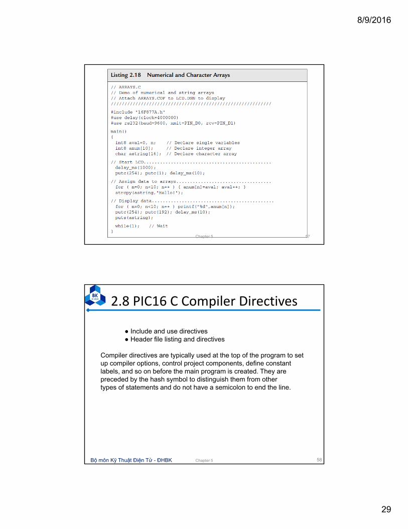
Compiler directives are typically used at the top of the program to set up compiler options, control project components, define constant labels, and so on before the main program is created. They are preceded by the hash symbol to distinguish them from othertypes of statements and do not have a semicolon to end the line.
2.8 PIC16 C Compiler Directives
Chapter 5 58

8/9/2016
30
Chapter 5 59
Chapter 5 60

8/9/2016
31
Chapter 5 61
Chapter 5 62

8/9/2016
32
Chapter 5 63
Chapter 5 64

8/9/2016
33
Chapter 5 65
Bộ môn Kỹ Thuật Điện Tử - ĐHBK
3. Timer and Interrupt• Interrupt:
– Interrupts allow an external event to initiate a control sequence that takes priority over the current MCU activity.
– The interrupt service routine (ISR) carries out some operation associated with the port or internal device that requested the interrupt.
– Interrupts are frequently used with hardware timers, which provide delays, timed intervals and measurement.
66Chapter 5

8/9/2016
34
Bộ môn Kỹ Thuật Điện Tử - ĐHBK
3. Timer and Interrupt
• PIC16F877 has 14 interrupt sources
67
No Interrupt Label Interrupt Source
1 INT_EXT External interrupt detect on RB0
2 INT_RB Change on Port B detect
3 INT_TIMER0 (INT_RTCC)
Timer 0 overflow
4 INT_TIMER1 Timer 1 overflow
5 INT_TIMER2 Timer 2 overflow
6 INT_CCP1 Timer 1 capture or compare detect
7 INT_CCP2 Timer 2 capture or compare detect
Chapter 5
Bộ môn Kỹ Thuật Điện Tử - ĐHBK
3. Timer and Interrupt
• PIC16F877 has 14 interrupt sources
68
No Interrupt Label Interrupt Source
8 INT_TBE USART transmit data done
9 INT_RDA USART receive data ready
10 INT_SSP Serial data received at SPI or I2C
11 INT_BUSCOL I2C collision detected
12 INT_PSP Data ready at parallel serial port
13 INT_AD Analog‐to‐digital converter complete
14 INT_EEPROM EEPROM write completion
Chapter 5

8/9/2016
35
Bộ môn Kỹ Thuật Điện Tử - ĐHBK
C Interrupts
• CCS C Interrupt Functions
69Chapter 5
Bộ môn Kỹ Thuật Điện Tử - ĐHBK
Interrupt example
70
RA0/AN02
RA1/AN13
RA2/AN2/VREF-4
RA4/T0CKI6
RA5/AN4/SS7
RE0/AN5/RD8
RE1/AN6/WR9
RE2/AN7/CS10
OSC1/CLKIN13
OSC2/CLKOUT14
RC1/T1OSI/CCP2 16
RC2/CCP1 17
RC3/SCK/SCL18
RD0/PSP0 19
RD1/PSP1 20
RB7/PGD40
RB6/PGC39
RB538
RB437
RB3/PGM 36RB2 35RB1 34
RB0/INT33
RD7/PSP730
RD6/PSP629
RD5/PSP528
RD4/PSP427
RD3/PSP322
RD2/PSP221
RC7/RX/DT26
RC6/TX/CK25
RC5/SDO24
RC4/SDI/SDA23
RA3/AN3/VREF+5
RC0/T1OSO/T1CKI 15
MCLR/Vpp/THV1
U1
PIC16F877
R110k
X1
4MHz
12345678
2019181716151413
910
1211
U2
23456789
1
RP1
220R
C1
15pF
C2
15pF
Chapter 5

8/9/2016
36
Bộ môn Kỹ Thuật Điện Tử - ĐHBK
Interrupt example
71
#include " 16F877A.h "#use delay(clock = 4000000)#int_ext // Interrupt namevoid isrext() { // Interrupt service routine
output_D(255); // ISR actiondelay_ms(1000);
}void main() {
int x;enable_interrupts(int_ext); // Enable named interruptenable_interrupts(global); // Enable all interruptsext_int_edge(H_TO_L); // Interrupt signal polaritywhile(1) { // Foreground loop
output_D(x); x + + ;delay_ms(100);
}}
Chapter 5
Bộ môn Kỹ Thuật Điện Tử - ĐHBK
Interrupt statements• #int_xxx
– Tells the compiler that the code immediately following is the service routine for this particular interrupt
– The interrupt name is preceded by #(hash) to mark the start of the ISR definition and to differentiate it from a standard function block.
– An interrupt name is defined for each interrupt source.
• enable_interrupts(int_ext);– Enables the named interrupt by loading the necessary codes into the interrupt control registers
72Chapter 5

8/9/2016
37
Bộ môn Kỹ Thuật Điện Tử - ĐHBK
Interrupt statements• enable_interrupts(level);
– Enables the interrupt at the given level.
– Examples: enable_interrupts(GLOBAL);
enable_interrupts(INT_TIMER0);
enable_interrupts(INT_TIMER1);
• Disable_interrupts(level)– Disable interrupt at the given level
• ext_int_edge(H_TO_L);– Enables the edge on which the edge interrupt should trigger. This can be either rising or falling edge.
73Chapter 5
Bộ môn Kỹ Thuật Điện Tử - ĐHBK
Class Assignment1. Write C code to enable an external interrupt
at RB0 with the trigger low to high
2. Write a C program to control 4 output pins RC0‐RC3 from 4 input pins RB4‐RB7 using port interrupt.
74Chapter 5

8/9/2016
38
Bộ môn Kỹ Thuật Điện Tử - ĐHBK
3. PIC16 Hardware Timers• The PIC 16F877 has three hardware timers built in:
– Timer0: 8‐bit, originally called RTCC, the real‐time counter clock
– Timer1: 16‐bit
– Timer2: 8‐bit
• The principal modes of operation
– Counters for external events
– Timers using the internal clock.
75Chapter 5
Bộ môn Kỹ Thuật Điện Tử - ĐHBK
Counter/Timer Operation• A counter/timer register consists of a set of bistable stages
(flip‐flops) connected in cascade (8, 16, or 32 bits).
• An 8‐bit counter counts up from 0x00 to 0xFF
76
Flag is set to 1 when overflow (7 to 0)
Chapter 5

8/9/2016
39
Bộ môn Kỹ Thuật Điện Tử - ĐHBK
Counter/Timer Operation
• Timer0 is an 8‐bit register that can count pulses at RA4; for this purpose, the input is called T0CKI (Timer0 clock input).
• Timer1 is a 16‐bit register that can count up to 0xFFFF (65,535) connected to RC0 (T1CKI) .
• The count can be recorded at any chosen point in time; alternatively, an interrupt can be generated on overflow to notify the processor that the maximum count has been exceeded.
• If the register is preloaded with a suitable value, the interrupt occurs after a known count.
• Timer0 has a prescaler that divides by up to 128;
• Timer1 has one that divides by 2, 4, or 8;
• Timer2 has a prescaler and postscaler that divide by up to 16.
77Chapter 5
Bộ môn Kỹ Thuật Điện Tử - ĐHBK
Timer Functions
Functions Description Examples
Setup_timer_x Setup timer setup_timer_0(RTCC_INTERNAL | RTCC_DIV_8);
Set_timerx(value) Set the value of the timer
Set_timer0(81);
Get_timerx() Get the value of the timer
int x = get_timer0();
Setup_ccpx(mode) Set PWM, capture, or compare mode
setup_ccp1(ccp_pwm);
Set_pwmx_duty(value) Set PWM duty cycle set_pwm1_duty(512);
78Chapter 5

8/9/2016
40
Bộ môn Kỹ Thuật Điện Tử - ĐHBK
Timer Functions• Setup_timer_0(mode)
– RTCC_INTERNAL, RTCC_EXT_L_TO_H or RTCC_EXT_H_TO_L
– RTCC_DIV_2, RTCC_DIV_4, RTCC_DIV_8, RTCC_DIV_16, RTCC_DIV_32, RTCC_DIV_64, RTCC_DIV_128, RTCC_DIV_256
• Setup_timer_1(mode)– T1_DISABLED, T1_INTERNAL, T1_EXTERNAL, T1_EXTERNAL_SYNC
– T1_CLK_OUT
– T1_DIV_BY_1, T1_DIV_BY_2, T1_DIV_BY_4, T1_DIV_BY_8
• Example:– setup_timer_0(RTCC_INTERNAL | RTCC_DIV_8)
– setup_timer_1 ( T1_DISABLED ); //disables timer1
– setup_timer_1 ( T1_INTERNAL | T1_DIV_BY_4 );
– setup_timer_1 ( T1_INTERNAL | T1_DIV_BY_8 );
79Chapter 5
Bộ môn Kỹ Thuật Điện Tử - ĐHBK
Timer Functions• setup_timer_2 (mode, period, postscale)
– modemay be one of T2_DISABLED, T2_DIV_BY_1, T2_DIV_BY_4, T2_DIV_BY_16
– period is a int 0‐255 that determines when the clock value is reset,
– postscale is a number 1‐16 that determines how many timer overflows before an interrupt: (1 means once, 2 means twice, and so on).
80Chapter 5
8/9/2016
41
Bộ môn Kỹ Thuật Điện Tử - ĐHBK
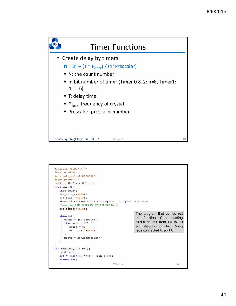
Timer Functions• Create delay by timers
N = 2n – (T * Fclock) / (4*Prescaler)
N: the count number
n: bit number of timer (Timer 0 & 2: n=8, Timer1: n = 16)
T: delay time
Fclock: frequency of crystal
Prescaler: prescaler number
81Chapter 5
82
The program that carries outthe function of a countingcircuit counts from 00 to 19and displays on two 7-segleds connected to port C
Chapter 5

8/9/2016
42
Bộ môn Kỹ Thuật Điện Tử - ĐHBK
PWM mode• In Pulse Width Modulation mode, a CCP module can be used to generate a timed output signal.
• This provides an output pulse waveform with an adjustable high (mark) period.
• CCS C functions:
Set_pwm1_duty(value);
Set_pwm2_duty(value);
duty cycle = value / [ 4 * (PR2 +1 ) ]
PR2 is the count value of timer 2
83Chapter 5
Bộ môn Kỹ Thuật Điện Tử - ĐHBK
PWM mode ‐ Example
#include " 16F877A.h "
void main()
{
setup_ccp1(ccp_pwm); // Select timer and mode
set_pwm1_duty(500); // Set on time
setup_timer_2(T2_DIV_BY_16,249,1); // Clock rate & output //period
while(1) { } // Wait until reset
}
84
Produce an output at CCP1 of 250Hz (4ms) and a mark-space ratio of 50% with a 4-MHz MCU clock. Explain?
Chapter 5

8/9/2016
43
Bộ môn Kỹ Thuật Điện Tử - ĐHBK
Compare Mode
• Generate a timed output in conjunction with Timer1.
• The 16‐bit CCPR register is preloaded with a set value, which is continuously compared with the Timer1 count. When the count matches the CCPR value, the output pin toggles and a CCP interrupt is generated. If this operation is repeated, an interrupt and output change with a known period can be obtained.
85Chapter 5
Bộ môn Kỹ Thuật Điện Tử - ĐHBK
Capture mode• The CCP pin is set to input and monitored for a change of state.
• When a rising or falling edge (selectable) is detected, the timer register is cleared to 0 and starts counting at the internal clock rate.
• When the next active edge is detected at the input, the timer register value is copied to the CCP register. The count therefore corresponds to the period of the input signal. With a 1MHz instruction clock, the count is in microseconds
86Chapter 5

8/9/2016
44
Bộ môn Kỹ Thuật Điện Tử - ĐHBK
Exercise – Timer Interrupt
87
1) Calculate the frequency of the pulse on PIN B0 created by the program on the right figure, given that FOSC = 4MHz
2) Write the program that create a 2Hz pulse on PIN_B1, given that FOSC = 4MHz and dutycycle = 20%
Chapter 5
Bộ môn Kỹ Thuật Điện Tử - ĐHBK
Class Assignment1. Write a program for PIC16F877 to create
rectangle pulses 2KHz at RB1 using interrupt Timer 0.
2. Write a C program for PIC16F877 to create rectangle pulses 0.5KHz and 1KHz at RC0 and RC1 with duty cycle 50%. Use Timer1 interrupt with 4MHz OSC.
3. Write the program that create a 2Hz pulse on PIN_B1, given that FOSC = 4MHz and dutycycle= 20%
88Chapter 5


![“Embedded Systems Design [ESD]“€¦ · Embedded Systems Design [ESD] Page C-6 University of Applied Sciences Bremerhaven Mechatronics As of: January 2016 F. Cellier: Continuous](https://img.dokumen.tips/doc/110x75/5f210f8391e61a479c690085/aoeembedded-systems-design-esdaoe-embedded-systems-design-esd-page-c-6-university.jpg)


![EC6101 DIGITAL COMMUNICATION TECHNIQUES1].pdfECB 692 SYSTEM DESIGN USING EMBEDDED PROCESSORS LAB L T ... ESD protection in equipment design, software and ESD ... E. Boyce, CMOS - Circuit](https://img.dokumen.tips/doc/110x75/5aae0cf97f8b9a07498b9809/ec6101-digital-communication-1pdfecb-692-system-design-using-embedded-processors.jpg)