Embed Size (px)
Citation preview

ĐẠI HỌC QUỐC GIA TP.HỒ CHÍ MINH
TRƯỜNG ĐẠI HỌC BÁCH KHOAKHOA ĐIỆN-ĐIỆN TỬ
BỘ MÔN KỸ THUẬT ĐIỆN TỬ
Bùi Minh Thành – Bộ Môn Kỹ Thuật Điện Tử - ĐHBK 11
Embedded System Design
Chapter 5: C Peripheral Interfaces
(Part 2)
Bùi Minh Thành - Bộ môn Kỹ Thuật Điện Tử - ĐHBK
References
• Martin Bates, “Programming 8-bit PIC Microcontrollers in C”, Newnes, 2008
• PIC 16F877A datasheet
• PIC C Help
2

Bùi Minh Thành - Bộ môn Kỹ Thuật Điện Tử - ĐHBK
Outline
1.PIC16 C Analog Input
2.PIC16 C Interrupts
3.PIC16 Hardware Timers
3

Bùi Minh Thành - Bộ môn Kỹ Thuật Điện Tử - ĐHBK
Outline
1.PIC16 C Analog Input
2.PIC16 C Interrupts
3.PIC16 Hardware Timers
4

Bùi Minh Thành - Bộ môn Kỹ Thuật Điện Tử - ĐHBK
1. PIC16 C Analog Input
• Allows an external voltage to be converted to digital form, stored and processed
• This type of input occurs in data loggers, control systems, digital audio and signal processors…
• The dsPIC range is designed specifically for high-speed analog signal processing
5
Bùi Minh Thành - Bộ môn Kỹ Thuật Điện Tử - ĐHBK
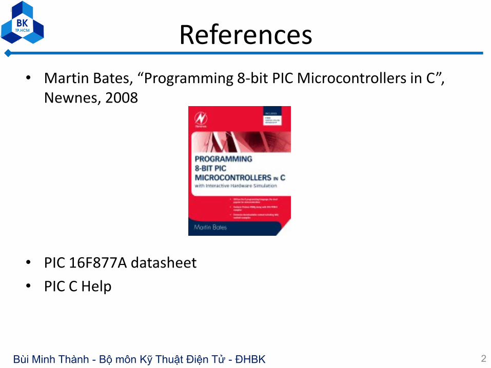
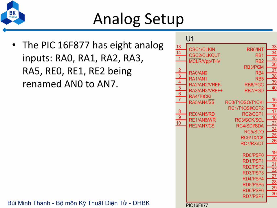
Analog Setup
• The PIC 16F877 has eight analog inputs: RA0, RA1, RA2, RA3, RA5, RE0, RE1, RE2 being renamed AN0 to AN7.
6
RA0/AN02
RA1/AN13
RA2/AN2/VREF-4
RA4/T0CKI6
RA5/AN4/SS7
RE0/AN5/RD8
RE1/AN6/WR9
RE2/AN7/CS10
OSC1/CLKIN13
OSC2/CLKOUT14
RC1/T1OSI/CCP216
RC2/CCP117
RC3/SCK/SCL18
RD0/PSP019
RD1/PSP120
RB7/PGD40
RB6/PGC39
RB538
RB437
RB3/PGM36
RB235
RB134
RB0/INT33
RD7/PSP730
RD6/PSP629
RD5/PSP528
RD4/PSP427
RD3/PSP322
RD2/PSP221
RC7/RX/DT26
RC6/TX/CK25
RC5/SDO24
RC4/SDI/SDA23
RA3/AN3/VREF+5
RC0/T1OSO/T1CKI15
MCLR/Vpp/THV1
U1
PIC16F877

Bùi Minh Thành - Bộ môn Kỹ Thuật Điện Tử - ĐHBK
A/D Block diagram
7
Bùi Minh Thành - Bộ môn Kỹ Thuật Điện Tử - ĐHBK
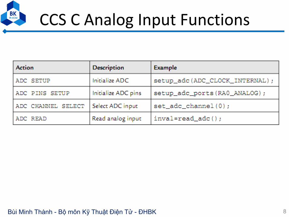
CCS C Analog Input Functions
8
Bùi Minh Thành - Bộ môn Kỹ Thuật Điện Tử - ĐHBK
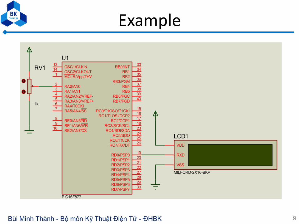
Example
9
RA0/AN02
RA1/AN13
RA2/AN2/VREF-4
RA4/T0CKI6
RA5/AN4/SS7
RE0/AN5/RD8
RE1/AN6/WR9
RE2/AN7/CS10
OSC1/CLKIN13
OSC2/CLKOUT14
RC1/T1OSI/CCP216
RC2/CCP117
RC3/SCK/SCL18
RD0/PSP019
RD1/PSP120
RB7/PGD40
RB6/PGC39
RB538
RB437
RB3/PGM36
RB235
RB134
RB0/INT33
RD7/PSP730
RD6/PSP629
RD5/PSP528
RD4/PSP427
RD3/PSP322
RD2/PSP221
RC7/RX/DT26
RC6/TX/CK25
RC5/SDO24
RC4/SDI/SDA23
RA3/AN3/VREF+5
RC0/T1OSO/T1CKI15
MCLR/Vpp/THV1
U1
PIC16F877
VSS
RXD
VDD
LCD1
MILFORD-2X16-BKP
RV1
1k

Bùi Minh Thành - Bộ môn Kỹ Thuật Điện Tử - ĐHBK
Example
10

Bùi Minh Thành - Bộ môn Kỹ Thuật Điện Tử - ĐHBK
Voltage measurement
11
RA0/AN02
RA1/AN13
RA2/AN2/VREF-4
RA4/T0CKI6
RA5/AN4/SS7
RE0/AN5/RD8
RE1/AN6/WR9
RE2/AN7/CS10
OSC1/CLKIN13
OSC2/CLKOUT14
RC1/T1OSI/CCP216
RC2/CCP117
RC3/SCK/SCL18
RD0/PSP019
RD1/PSP120
RB7/PGD40
RB6/PGC39
RB538
RB437
RB3/PGM36
RB235
RB134
RB0/INT33
RD7/PSP730
RD6/PSP629
RD5/PSP528
RD4/PSP427
RD3/PSP322
RD2/PSP221
RC7/RX/DT26
RC6/TX/CK25
RC5/SDO24
RC4/SDI/SDA23
RA3/AN3/VREF+5
RC0/T1OSO/T1CKI15
MCLR/Vpp/THV1
U1
PIC16F877
VSS
RXD
VDD
LCD1
MILFORD-2X16-BKP
D1
BZX79C2V7
R1680R
RV2
1k
R24k7
RV1
1k
RV3
1k
RV4
1k
RV5
1k
RV6
1k
RV7
1k
RV8
1k
R3
120R
U1(RA3/AN3/VREF+)V=2.55838
RV5(1)V=2.71739

Bùi Minh Thành - Bộ môn Kỹ Thuật Điện Tử - ĐHBK
Voltage measurement
12

Bùi Minh Thành - Bộ môn Kỹ Thuật Điện Tử - ĐHBK
Outline
1.PIC16 C Analog Input
2.PIC16 C Interrupts
3.PIC16 Hardware Timers
13

Bùi Minh Thành - Bộ môn Kỹ Thuật Điện Tử - ĐHBK
2. PIC16 C Interrupts
• Interrupts allow an external event to initiate a control sequence that takes priority over the current MCU activity.
• The interrupt service routine (ISR) carries out some operation associated with the port or internal device that requested the interrupt.
• Interrupts are frequently used with hardware timers, which provide delays, timed intervals and measurement.
• PIC16F877 has 14 interrupt sources
14

Bùi Minh Thành - Bộ môn Kỹ Thuật Điện Tử - ĐHBK
C Interrupts
• CCS C Interrupt Functions
15

Bùi Minh Thành - Bộ môn Kỹ Thuật Điện Tử - ĐHBK
C Interrupts – Interrupt sourcesPIC16 F877 Primary Interrupt
16
PIC16 F877 Peripheral Interrupts

Bùi Minh Thành - Bộ môn Kỹ Thuật Điện Tử - ĐHBK
Interrupt Sources
17

Bùi Minh Thành - Bộ môn Kỹ Thuật Điện Tử - ĐHBK
Interrupt example
18
RA0/AN02
RA1/AN13
RA2/AN2/VREF-4
RA4/T0CKI6
RA5/AN4/SS7
RE0/AN5/RD8
RE1/AN6/WR9
RE2/AN7/CS10
OSC1/CLKIN13
OSC2/CLKOUT14
RC1/T1OSI/CCP216
RC2/CCP117
RC3/SCK/SCL18
RD0/PSP019
RD1/PSP120
RB7/PGD40
RB6/PGC39
RB538
RB437
RB3/PGM36
RB235
RB134
RB0/INT33
RD7/PSP730
RD6/PSP629
RD5/PSP528
RD4/PSP427
RD3/PSP322
RD2/PSP221
RC7/RX/DT26
RC6/TX/CK25
RC5/SDO24
RC4/SDI/SDA23
RA3/AN3/VREF+5
RC0/T1OSO/T1CKI15
MCLR/Vpp/THV1
U1
PIC16F877
R110k
X1
4MHz
1
2
3
4
5
6
7
8
20
19
18
17
16
15
14
13
9
10
12
11
U2
2
3
4
5
6
7
8
9
1
RP1
220R
C1
15pF
C2
15pF

Bùi Minh Thành - Bộ môn Kỹ Thuật Điện Tử - ĐHBK
Interrupt example
19

Bùi Minh Thành - Bộ môn Kỹ Thuật Điện Tử - ĐHBK
Interrupt statements
• #int_xxx– Tells the compiler that the code immediately following is the
service routine for this particular interrupt
– The interrupt name is preceded by #(hash) to mark the start of the ISR definition and to differentiate it from a standard function block.
– An interrupt name is defined for each interrupt source.
• enable_interrupts(int_ext);– Enables the named interrupt by loading the necessary codes
into the interrupt control registers
20

Bùi Minh Thành - Bộ môn Kỹ Thuật Điện Tử - ĐHBK
Interrupt statements
• enable_interrupts(level);– Enables the interrupt at the given level.
– Examples: enable_interrupts(GLOBAL);
enable_interrupts(INT_TIMER0);
enable_interrupts(INT_TIMER1);
• Disable_interrupts(level)– Disable interrupt at the given level
• ext_int_edge(H_TO_L);– Enables the edge on which the edge interrupt should trigger.
This can be either rising or falling edge.
21
Bùi Minh Thành - Bộ môn Kỹ Thuật Điện Tử - ĐHBK
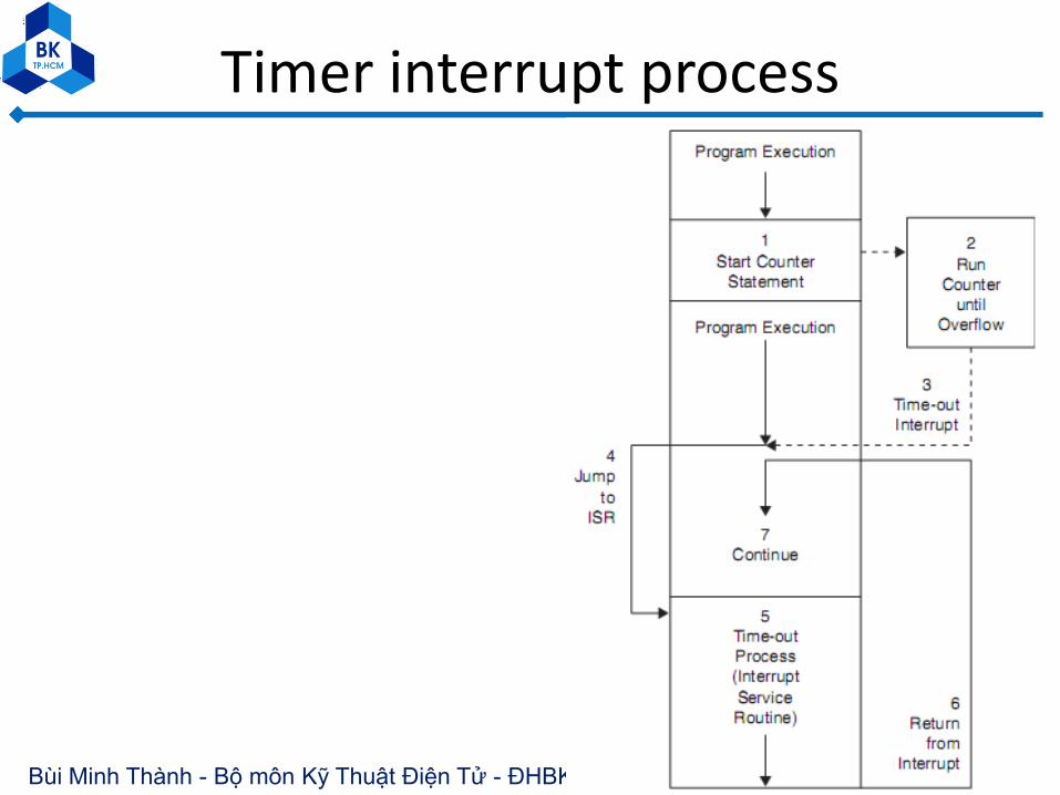
Timer interrupt process
22
Bùi Minh Thành - Bộ môn Kỹ Thuật Điện Tử - ĐHBK
Outline
1.PIC16 C Analog Input
2.PIC16 C Interrupts
3.PIC16 Hardware Timers
23

Bùi Minh Thành - Bộ môn Kỹ Thuật Điện Tử - ĐHBK
3. PIC16 Hardware Timers
• The PIC 16F877 has three hardware timers built in: Timer0 (8-bit) (originally called RTCC, the real-time counter clock), Timer1 (16-bit), and Timer2 (8-bit).
• The principal mode of operation of these registers are as counters for external events or timers using the internal clock.
• Additional registers are used to provide Capture, Compare, and Pulse Width Modulation (PWM) modes
24

Bùi Minh Thành - Bộ môn Kỹ Thuật Điện Tử - ĐHBK
Counter/Timer Operation
• A counter/timer register consists of a set of bistable stages (flip-flops) connected in cascade (8, 16, or 32 bits).
• An 8-bit counter counts up from 0x00 to 0xFF 25
Flag is set to 1 when overflow (7 to 0)

Bùi Minh Thành - Bộ môn Kỹ Thuật Điện Tử - ĐHBK
Counter/Timer Operation
• Timer0 is an 8-bit register that can count pulses at RA4; for this purpose, the input is called T0CKI (Timer0 clock input).
• Timer1 is a 16-bit register that can count up to 0xFFFF (65,535) connected to RC0 (T1CKI) .
• The count can be recorded at any chosen point in time; alternatively, an interrupt can be generated on overflow to notify the processor that the maximum count has been exceeded.
• If the register is preloaded with a suitable value, the interrupt occurs after a known count.
• Timer0 has a prescaler that divides by up to 128;
• Timer1 has one that divides by 2, 4, or 8;
• Timer2 has a prescaler and postscaler that divide by up to 16.
26

Bùi Minh Thành - Bộ môn Kỹ Thuật Điện Tử - ĐHBK
Timer Functions
27

Bùi Minh Thành - Bộ môn Kỹ Thuật Điện Tử - ĐHBK
Exercise
28
A7
A7
L0
L7
A6
A4
A3
A1
A2
A0
A0
A1
A2
A3
A4
A5
A6
L1
L2
L3
L4
L5
L6
L7
L0
L1
L2
L3
L4
L5
L6
C7
C3
C0
C1
C2
C4
C5
C6
C7
C6 C
5
C4 C
3 C1
A5
C0
C2
RA0/AN02
RA1/AN13
RA2/AN2/VREF-/CVREF4
RA4/T0CKI/C1OUT6
RA5/AN4/SS/C2OUT7
RE0/AN5/RD8
RE1/AN6/WR9
RE2/AN7/CS10
OSC1/CLKIN13
OSC2/CLKOUT14
RC1/T1OSI/CCP216
RC2/CCP117
RC3/SCK/SCL18
RD0/PSP019
RD1/PSP120
RB7/PGD40
RB6/PGC39
RB538
RB437
RB3/PGM36
RB235
RB134
RB0/INT33
RD7/PSP730
RD6/PSP629
RD5/PSP528
RD4/PSP427
RD3/PSP322
RD2/PSP221
RC7/RX/DT26
RC6/TX/CK25
RC5/SDO24
RC4/SDI/SDA23
RA3/AN3/VREF+5
RC0/T1OSO/T1CKI15
MCLR/Vpp/THV1
U1
PIC16F877A
R110k
2
3
4
5
6
7
8
9
1
RP1
RESPACK-8
D1LED-BIRY
D2LED-BIRY
D3LED-BIRY
D4LED-BIRY
D5LED-BIRY
D6LED-BIRY
D7LED-BIRY
D8
LED-BIRY
A7
QA13
B1
QB12
C2
QC11
D6
QD10
BI/RBO4
QE9
RBI5
QF15
LT3
QG14
U2
74LS47
100%
RV1
1k
+88.8
Volts
+88.8
Volts

Bùi Minh Thành - Bộ môn Kỹ Thuật Điện Tử - ĐHBK 29
The program that carries out
the function of a counting
circuit counts from 00 to 19
and displays on two 7-seg
leds connected to port C

Bùi Minh Thành - Bộ môn Kỹ Thuật Điện Tử - ĐHBK
C source code with Assembly block
30
If the MCU clock
is 20MHz
the output
frequency is
1.25MHz.

Bùi Minh Thành - Bộ môn Kỹ Thuật Điện Tử - ĐHBK
PWM mode
• In Pulse Width Modulation mode, a CCP module can be used to generate a timed output signal.
• This provides an output pulse waveform with an adjustable high (mark) period.
31

Bùi Minh Thành - Bộ môn Kỹ Thuật Điện Tử - ĐHBK
PWM mode - Example
32
Produce an output at CCP1 of 250Hz (4ms) and a mark-space ratio of 50%
with a 4-MHz MCU clock. Explain?

Bùi Minh Thành - Bộ môn Kỹ Thuật Điện Tử - ĐHBK
Compare Mode
• Generate a timed output in conjunction with Timer1.
• The 16-bit CCPR register is preloaded with a set value, which is continuously compared with the Timer1 count. When the count matches the CCPR value, the output pin toggles and a CCP interrupt is generated. If this operation is repeated, an interrupt and output change with a known period can be obtained.
33

Bùi Minh Thành - Bộ môn Kỹ Thuật Điện Tử - ĐHBK
Capture mode• The CCP pin is set to input and monitored for a change of state.
• When a rising or falling edge (selectable) is detected, the timer register is cleared to 0 and starts counting at the internal clock rate.
• When the next active edge is detected at the input, the timer register value is copied to the CCP register. The count therefore corresponds to the period of the input signal. With a 1MHz instruction clock, the count is in microseconds
34
Bùi Minh Thành - Bộ môn Kỹ Thuật Điện Tử - ĐHBK
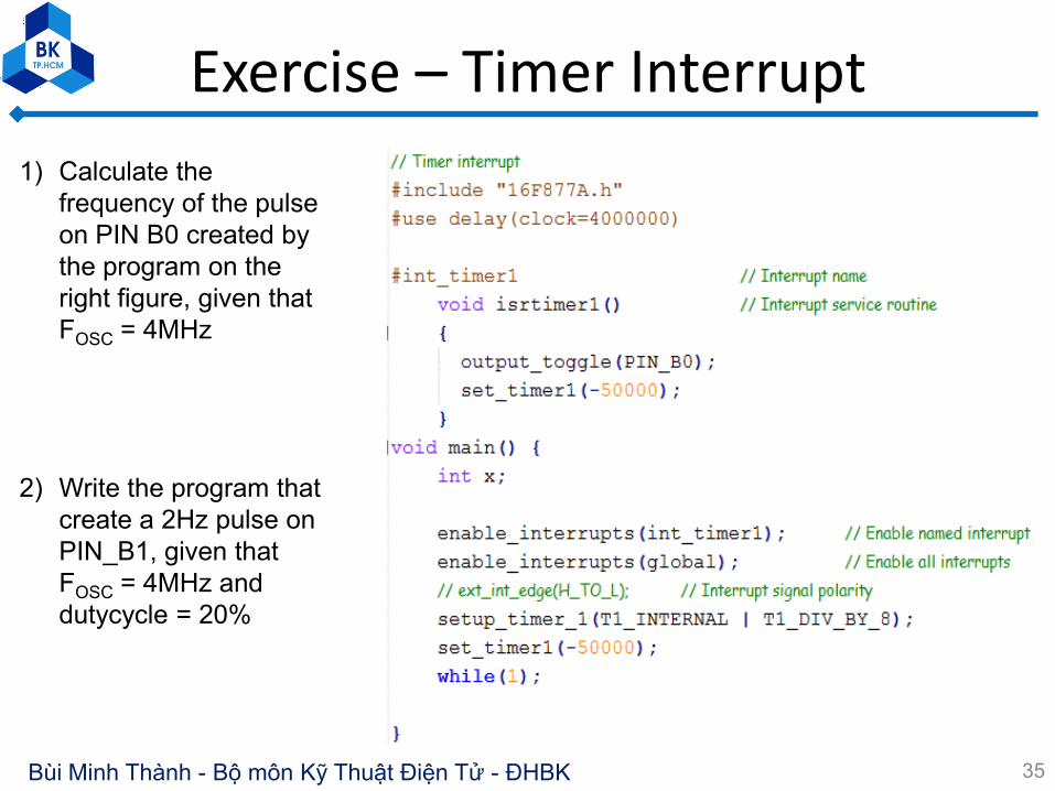
Exercise – Timer Interrupt
35
1) Calculate the
frequency of the pulse
on PIN B0 created by
the program on the
right figure, given that
FOSC = 4MHz
2) Write the program that
create a 2Hz pulse on
PIN_B1, given that
FOSC = 4MHz and
dutycycle = 20%