Embed Size (px)
Citation preview

Embedded Intel® Atom™ Processor
N2800 with Intel® NM10 Express
Chipset
Development Kit User’s Manual
February 2012
Document Number: 326570

Embedded Intel® Atom™ Processor N2800 with Intel® NM10 Express Chipset Development Kit User‘s Manual
2
Revision History
Revision Revision History Date
001 First release of the Intel® Atom™ Processor N2800 with Intel® NM10
Express Chipset Development Kit User Guide
January 2012
002 Updated link in Section 7 February 2012
Disclaimer
This product specification applies to only the standard Intel® Embedded Board N2800 with BIOS
identifier MTCDT10N.86A.
INFORMATION IN THIS DOCUMENT IS PROVIDED IN CONNECTION WITH INTEL PRODUCTS. NO LICENSE,
EXPRESS OR IMPLIED, BY ESTOPPEL OR OTHERWISE, TO ANY INTELLECTUAL PROPERTY RIGHTS IS
GRANTED BY THIS DOCUMENT. EXCEPT AS PROVIDED IN INTEL'S TERMS AND CONDITIONS OF SALE FOR
SUCH PRODUCTS, INTEL ASSUMES NO LIABILITY WHATSOEVER AND INTEL DISCLAIMS ANY EXPRESS OR
IMPLIED WARRANTY, RELATING TO SALE AND/OR USE OF INTEL PRODUCTS INCLUDING LIABILITY OR
WARRANTIES RELATING TO FITNESS FOR A PARTICULAR PURPOSE, MERCHANTABILITY, OR
INFRINGEMENT OF ANY PATENT, COPYRIGHT OR OTHER INTELLECTUAL PROPERTY RIGHT.
A "Mission Critical Application" is any application in which failure of the Intel Product could result, directly or
indirectly, in personal injury or death. SHOULD YOU PURCHASE OR USE INTEL'S PRODUCTS FOR ANY
SUCH MISSION CRITICAL APPLICATION, YOU SHALL INDEMNIFY AND HOLD INTEL AND ITS
SUBSIDIARIES, SUBCONTRACTORS AND AFFILIATES, AND THE DIRECTORS, OFFICERS, AND EMPLOYEES
OF EACH, HARMLESS AGAINST ALL CLAIMS COSTS, DAMAGES, AND EXPENSES AND REASONABLE
ATTORNEYS' FEES ARISING OUT OF, DIRECTLY OR INDIRECTLY, ANY CLAIM OF PRODUCT LIABILITY,
PERSONAL INJURY, OR DEATH ARISING IN ANY WAY OUT OF SUCH MISSION CRITICAL APPLICATION,
WHETHER OR NOT INTEL OR ITS SUBCONTRACTOR WAS NEGLIGENT IN THE DESIGN, MANUFACTURE, OR
WARNING OF THE INTEL PRODUCT OR ANY OF ITS PARTS.
Intel may make changes to specifications and product descriptions at any time, without notice. Designers
must not rely on the absence or characteristics of any features or instructions marked "reserved" or
"undefined". Intel reserves these for future definition and shall have no responsibility whatsoever for
conflicts or incompatibilities arising from future changes to them. The information here is subject to change
without notice. Do not finalize a design with this information.
The products described in this document may contain design defects or errors known as errata which may
cause the product to deviate from published specifications. Current characterized errata are available on
request.
Contact your local Intel sales office or your distributor to obtain the latest specifications and before placing
your product order.
Copies of documents which have an order number and are referenced in this document, or other Intel
literature, may be obtained by calling 1-800-548-4725, or go to:
http://www.intel.com/design/literature.htm
Intel, the Intel logo, and Intel Atom are trademarks of Intel Corporation in the U.S. and/or other countries.
* Other names and brands may be claimed as the property of others.
Copyright © 2012, Intel Corporation. All rights reserved..

Embedded Intel® Atom™ Processor N2800 with Intel® NM10 Express Chipset Development Kit User‘s Manual
3
Component Information
The Intel® AtomTM Processor N2800 and Intel® NM10 Express Chipset used on the Intel® Embedded Board N2800 include the following component steppings, identifiable by associated S-Spec numbers:
Device Stepping S-Spec Number
N2800 B2 SR0DA
NM10 B0 SLGXX
Ordering Information The name of this Development Kit is the Intel® Atom™ Processor N2800 with Intel® NM10
Express Chipset Development Kit. This document is the user guide for this Kit. For ordering purposes, the Part Number of this Kit is EMBCDTNMMTDVK and the Kit‘s product code is MM# 920354. The product brief and other collaterals for the platform can be downloaded at: http://www.intel.com/p/en_US/embedded/hwsw/hardware/atom-n2000-d2000/hardware This kit comprises a chassis, peripherals, cables, and an Intel mini-ITX sized N2800 Embedded Board which includes the two Intel devices which comprise the platform - the Intel® Atom™ processor N2800 and Intel® NM10 Express chipset. In addition, this kit includes several adapter boards and a Solid State Disk (SSD) for the Operating System Image, and a USB Stick for additional components, and tools.

Embedded Intel® Atom™ Processor N2800 with Intel® NM10 Express Chipset Development Kit User‘s Manual
4
Preface This User‘s Manual describes the typical hardware set-up procedures, features, and
use of the evaluation board and other components included in the Intel® Atom™
Processor N2800 with Intel® NM10 Express Development Kit. The Intel® Embedded
Board N2800 is mounted inside the Development Kit and functions as the mainboard
for the entire mini-ITX chassis.
Intended Audience
This manual is written for OEMs, system evaluators, and embedded system
developers. The manual is intended to provide detailed, technical information about
the development kit and its components. It is not intended for general audiences and
assumes the reader has basic familiarity with the fundamental concepts involved
with installing and configuring hardware for a personal computer system.
What This Document Contains
Chapter Description
1 Development kit contents
2 Embedded Board hardware and contents
3 A map of the resources of the Intel Embedded Board
4 The features supported by the BIOS
5 A description of the BIOS error messages, beep codes, and POST codes
6 Disassembling/Assembling the development kit
7 Operating System references
8 Battery disposal information
Typographical Conventions
This section contains information about the conventions used in this specification.
Not all of these symbols and abbreviations appear in all specifications of this type.
Notes, Cautions, and Warnings
NOTE
Notes call attention to important information.
CAUTION
Cautions are included to help you avoid damaging hardware or losing data.

Embedded Intel® Atom™ Processor N2800 with Intel® NM10 Express Chipset Development Kit User‘s Manual
5
Other Common Notation
# Used after a signal name to identify an active-low signal (such as USBP0#)
GB Gigabyte (1,073,741,824 bytes)
GB/s Gigabytes per second
Gb/s Gigabits per second
KB Kilobyte (1024 bytes)
Kbit Kilobit (1024 bits)
kbits/s 1000 bits per second
MB Megabyte (1,048,576 bytes)
MB/s Megabytes per second
Mbit Megabit (1,048,576 bits)
Mbits/s Megabits per second
TDP Thermal Design Power
xxh An address or data value ending with a lowercase h indicates a hexadecimal value.
x.x V Volts. Voltages are DC unless otherwise specified.
* This symbol is used to indicate third-party brands and names that are the property of their
respective owners.

Embedded Intel® Atom™ Processor N2800 with Intel® NM10 Express Chipset Development Kit User‘s Manual
6
Contents
1 Development Kit Contents ................................................... 12
1.1 Included Hardware and Documentation ............................................... 12 1.2 Development Kit Preview ................................................................... 13
2 Intel® Embedded Board N2800 Overview ............................ 14
2.1 Overview ......................................................................................... 14 2.1.1 Feature Summary ................................................................. 14 2.1.2 Embedded Board Layout (Top) ................................................ 16 2.1.3 Embedded Board Layout (Bottom) ........................................... 18 2.1.4 Block Diagram ...................................................................... 19
2.2 Online Support ................................................................................. 20 2.3 Supported Operating Systems ............................................................ 20 2.4 BIOS vendors ................................................................................... 21 2.5 Processor ........................................................................................ 21
2.5.1 Intel® Embedded Board N2800 Graphics Subsystem .................. 22 2.6 System Memory ............................................................................... 24 2.7 Intel® NM10 Express Chipset .............................................................. 27 2.8 Graphics Subsystem ......................................................................... 27
2.8.1 Integrated Graphics ............................................................... 27 2.8.2 Flat Panel Display Interfaces ................................................... 29 2.8.3 USB ..................................................................................... 33
2.9 SATA Interfaces ............................................................................... 34 2.9.1 AHCI Mode ........................................................................... 34
2.10 Real-Time Clock Subsystem ............................................................... 35 2.11 Legacy I/O Controller ........................................................................ 35
2.11.1 Serial Ports ........................................................................... 35 2.11.2 Parallel Port .......................................................................... 36
2.12 Audio Subsystem .............................................................................. 37 2.12.1 Audio Subsystem Software ..................................................... 38 2.12.2 Audio Subsystem Components ................................................ 38
2.13 LAN Subsystem ................................................................................ 40 2.13.1 Intel® 82574L Gigabit Ethernet Controller ................................. 40 2.13.2 LAN Subsystem Software & Drivers ......................................... 41 2.13.3 RJ-45 LAN Connector with Integrated LEDs .............................. 41
2.14 Hardware Management Subsystem ..................................................... 42 2.14.1 Hardware Monitoring ............................................................. 42 2.14.2 Fan Monitoring ...................................................................... 42 2.14.3 Thermal Monitoring ............................................................... 43
2.15 Power Management .......................................................................... 44

Embedded Intel® Atom™ Processor N2800 with Intel® NM10 Express Chipset Development Kit User‘s Manual
7
2.15.1 ACPI ............................................................................. 44 2.15.2 Hardware Support ................................................................. 46
2.16 Debug Interfaces .............................................................................. 49
3 Technical Reference ............................................................ 50
3.1 Memory Resources ........................................................................... 50 3.1.1 Addressable Memory ............................................................. 50 3.1.2 Memory Map ......................................................................... 52
3.2 Connectors and Headers .................................................................... 52 3.2.1 Back Panel Connectors ........................................................... 53 3.2.2 Connectors and Headers (Top) ................................................ 54 3.2.3 Connectors and Headers (Bottom) ........................................... 56
3.3 I/O Shields ...................................................................................... 70 3.4 Jumper Block ................................................................................... 71 3.5 Mechanical Considerations ................................................................. 73
3.5.1 Form Factor .......................................................................... 73 3.6 Electrical Considerations .................................................................... 75
3.6.1 Power Supply Considerations .................................................. 75 3.6.2 Connecting a System Fan & Fan Header Current Capability ......... 76 3.6.3 PCI Express* Add-in Card Considerations ................................. 76 3.6.4 Connecting to SATA Drive Considerations ................................. 79
3.7 Reliability......................................................................................... 81 3.8 Environmental .................................................................................. 81
4 Overview of BIOS Features ................................................. 82
4.1 Introduction ..................................................................................... 82 4.2 BIOS Flash Memory Organization ........................................................ 83 4.3 System Management BIOS (SMBIOS) ................................................. 84 4.4 Legacy USB Support ......................................................................... 84 4.5 BIOS Updates .................................................................................. 85
4.5.1 Updating the BIOS with the Intel® Express BIOS Update Utility .. 85 4.5.2 Updating the BIOS Using the F7 Function Key ........................... 86 4.5.3 Updating the BIOS with the Intel® Flash Memory Update Utility .. 86 4.5.4 Language Support ................................................................. 87 4.5.5 Custom Splash Screen ........................................................... 87
4.6 BIOS Recovery ................................................................................. 87 4.7 Boot Options .................................................................................... 88
4.7.1 Optical Drive Boot ................................................................. 88 4.7.2 Network Boot ........................................................................ 88 4.7.3 Booting Without Attached Devices ........................................... 89 4.7.4 Changing the Default Boot Device During POST ......................... 89
4.8 Adjusting Boot Speed ........................................................................ 89 4.8.1 Peripheral Selection and Configuration ..................................... 89
4.9 Hard Disk Drive Password Security Feature .......................................... 89 4.10 BIOS Security Features ..................................................................... 90

Embedded Intel® Atom™ Processor N2800 with Intel® NM10 Express Chipset Development Kit User‘s Manual
8
5 Error Messages and Beep Codes .......................................... 92
5.1 Speaker .......................................................................................... 92 5.2 BIOS Beep Codes ............................................................................. 92 5.3 Front-panel Power LED Blink Codes ..................................................... 93 5.4 BIOS Error Messages ........................................................................ 93 5.5 Port 80h POST Codes ........................................................................ 94
6 Assembly/Disassembly Guide ............................................. 99
6.1 Introduction ..................................................................................... 99 6.2 Required tools .................................................................................. 99 6.3 Board Installation Steps .................................................................... 99 6.4 Installing USB devices under the front plate ........................................ 100 6.5 Installing SSD and Fans .................................................................... 102
7 Operating System Reference ............................................. 103
7.1 Installing Windows* 7 ...................................................................... 103 7.1.1 Downloading and installing Windows 7 onto the Target SSD/HDD103 7.1.2 Downloading and installing processor, graphics, chipset and other
optional drivers .................................................................... 105 7.2 Installing Windows* Embedded Standard 7 ......................................... 105
7.2.1 Downloading, burning, and installing the WES7 DVD image ....... 106 7.2.2 Install WES7 ........................................................................ 106 7.2.3 Downloading and installing processor, graphics, chipset and other
optional drivers .................................................................... 110 7.3 Installing Windows Embedded Compact 7* ......................................... 111 7.4 Installing Windows XP* .................................................................... 111
7.4.1 Overview ............................................................................. 111 7.4.2 F6 install with floppy ............................................................. 112 7.4.3 Slipstream install .................................................................. 116 7.4.4 Install Device Drivers ............................................................ 119 7.4.5 Install and configure EMGD .................................................... 119
7.5 Using MeeGo* ................................................................................. 120 7.5.1 Booting MeeGo* ................................................................... 120 7.5.2 Live Image on USB stick ........................................................ 120 7.5.3 Install with USB stick ............................................................ 121 7.5.4 Graphics Driver .................................................................... 122 7.5.5 Flash .................................................................................. 122
7.6 Using Yocto Project* ........................................................................ 122 7.6.1 Booting Yocto Project* .......................................................... 123 7.6.2 Live Image on USB stick ........................................................ 123 7.6.3 Install with USB stick ............................................................ 124 7.6.4 Install with CD or DVD .......................................................... 125 7.6.5 Graphics Driver .................................................................... 125
8 Battery Disposal Information ............................................ 126

Embedded Intel® Atom™ Processor N2800 with Intel® NM10 Express Chipset Development Kit User‘s Manual
9
Figures
Figure 1. Major Board Components (Top) ................................................... 16 Figure 2. Major Board Components (Bottom) .............................................. 18 Figure 3. Block Diagram of Development Kit ............................................... 19 Figure 4. SO-DIMM Configuration .............................................................. 26 Figure 5. Flat Panel Connectors ................................................................. 29 Figure 6. Back Panel Audio Connectors ...................................................... 38 Figure 7. Internal Audio Headers ............................................................... 39 Figure 8. LAN Connector LED Locations ...................................................... 41 Figure 9. Thermal Sensor and Fan Header .................................................. 43 Figure 10. Location of the Standby Power LED ............................................ 49 Figure 11. Detailed System Memory Address Map ....................................... 51 Figure 12. Back Panel Connectors ............................................................. 53 Figure 13. Connectors and Headers (Top) .................................................. 54 Figure 14. Connectors and Headers (Bottom) ............................................. 56 Figure 15. Connection Diagram for Front Panel Header ................................ 66 Figure 16. Connection Diagram for Front Panel USB Dual-Port Header ........... 68 Figure 17. Connection Diagram for Front Panel USB Dual-Port Header (with Intel
Z-U130 USB Solid-State Drive, or Compatible SSD, Support) ................... 68 Figure 18. Half-Height Back Panel I/O Shield .............................................. 70 Figure 19. Standard-Height Back Panel I/O Shield ....................................... 71 Figure 20. Location of the Jumper Block ..................................................... 72 Figure 21. Board Dimensions .................................................................... 74 Figure 22. Location of the Chassis Fan Header ............................................ 76 Figure 23. Installing a PCI Express Mini Card in the Full-/Half-Mini Card Slot .... 78 Figure 24. Installing a PCI Express Mini Card in the Half-Mini Card Slot ........... 79 Figure 25. Connecting the SATA Data and Power Cables ............................... 80 Figure 26. Removing the top lid ................................................................. 99 Figure 27. Install Motherboard .................................................................. 100 Figure 28. J2 (USB Header) and J3 (2x3) pin header, view from the back of
Enclosure ......................................................................................... 100 Figure 29. Removing the front plate by pressing the left and right plastic lids . 101 Figure 30. JP1, JP2 pin header and 2 x USB slots ........................................ 101 Figure 31. Mounting Bracket for SDD, HDD, or Fan ...................................... 102 Figure 32: Build an image ........................................................................ 107 Figure 33: Accept the license terms ........................................................... 107 Figure 34: View template ......................................................................... 108 Figure 35: Template details ...................................................................... 108 Figure 36: Choose a language and other preferences ................................... 109 Figure 37: Where do you want to install Windows? ...................................... 109 Figure 38: Installing Windows ................................................................... 110 Figure 39: Set up Windows - Login ............................................................ 110
Embedded Intel® Atom™ Processor N2800 with Intel® NM10 Express Chipset Development Kit User‘s Manual
10
Tables
Table 1. Feature Summary ....................................................................... 14 Table 2. Components Shown in Figure 1 .................................................... 17 Table 3. Components Shown in Figure 2 .................................................... 18 Table 4. Maximum Resolutions Supported by the Intel® Atom™ Processor N2800
with Intel® NM10 Express Chipset Graphic interfaces ............................. 23 Table 5. Supported Memory Configurations ................................................ 25 Table 6. HDMI Port Status Conditions ........................................................ 28 Table 7. Audio Jack Support ..................................................................... 37 Table 8. LAN Connector LED States ........................................................... 41 Table 9. Effects of Pressing the Power Switch ............................................. 44 Table 10. Power States and Targeted System Power .................................... 45 Table 11. Wake-up Devices and Events ...................................................... 46 Table 12. System Memory Map ................................................................. 52 Table 13. Connectors and Headers Shown in Figure 13 ................................ 55 Table 14. Connectors and Headers Shown in Figure 14 ................................ 56 Table 15. Front Panel Audio Header for Intel HD Audio ................................. 57 Table 16. Front Panel Audio Header for AC‘97 Audio .................................... 57 Table 17. Internal Stereo Speakers Header ................................................ 58 Table 18. Internal S/PDIF Header .............................................................. 58 Table 19. Internal DMIC Header ................................................................ 58 Table 20. Front Panel USB Dual-Port Header ............................................... 58 Table 21. Front Panel USB Dual-Port Header (with support for Intel Z-U130 USB
Solid-State Drive or compatible SSD) .................................................... 58 Table 22. Serial Port Headers ................................................................... 59 Table 23. Parallel Port Header ................................................................... 59 Table 24. SATA Connectors ...................................................................... 60 Table 25. SATA Power Connector .............................................................. 60 Table 26. Custom Solutions Header ........................................................... 60 Table 27. System Fan Header ................................................................... 61 Table 28. Flat Panel Voltage Selection Header ............................................. 61 Table 29. Backlight Inverter Voltage Selection Header ................................. 61 Table 30. 40-Pin LVDS Connector .............................................................. 62 Table 31. 40-Pin eDP Connector ................................................................ 63 Table 32. 8-Pin FPD Brightness Connector .................................................. 63 Table 33. PCI Express Full-/Half-Mini Card Connector .................................. 64 Table 34. Internal Power Supply Connector Pinout ....................................... 66 Table 35. Front Panel Header .................................................................... 66 Table 36. States for a One-Color Power LED ............................................... 67 Table 37. Debug Header .......................................................................... 69 Table 38. BIOS Setup Configuration Jumper Settings ................................... 72 Table 39. Fan Header Current Capability .................................................... 76 Table 40. Embedded Board Environmental Specifications ............................. 81 Table 41. BIOS Setup Program Menu Bar ................................................... 83 Table 42. BIOS Setup Program Function Keys ............................................. 83 Table 43. Acceptable Drives/Media Types for BIOS Recovery ........................ 88

Embedded Intel® Atom™ Processor N2800 with Intel® NM10 Express Chipset Development Kit User‘s Manual
11
Table 44. Boot Device Menu Options .......................................................... 89 Table 45. Master Key and User Hard Drive Password Functions ..................... 90 Table 46. Supervisor and User Password Functions ...................................... 91 Table 47. BIOS Beep Codes ...................................................................... 92 Table 48. Front-panel Power LED Blink Codes ............................................. 93 Table 49. BIOS Error Messages ................................................................. 93 Table 50. Port 80h POST Code Ranges ....................................................... 94 Table 51. Port 80h POST Codes ................................................................. 95 Table 52. Typical Port 80h POST Sequence ................................................. 98 Table 53. Windows 7 Installation Options .................................................. 104

Embedded Intel® Atom™ Processor N2800 with Intel® NM10 Express Chipset Development Kit User‘s Manual
12
1 Development Kit Contents
1.1 Included Hardware and Documentation Each development kit ships as a complete system in a mini-ITX chassis (Size: 192 x 210 x
62mm.)
Intel Embedded Board N2800 with Intel® Atom™ Processor N2800 with Intel® NM10 Express
Chipset
2GB DDR3- 1066 MT/s non-ECC memory SODIMM
SSD (Solid State Disk), with a Yocto Project* based Linux Operating System pre-installed, with
power and SATA extension cable
Power supply-60W Desktop type AC/DC switching mode power supply
USB Stick with documentation and software

Embedded Intel® Atom™ Processor N2800 with Intel® NM10 Express Chipset Development Kit User‘s Manual
13
1.2 Development Kit Preview
1.2.1.1 Front
1.2.1.2 Inside
1.2.1.3 Back

Embedded Intel® Atom™ Processor N2800 with Intel® NM10 Express Chipset Development Kit User‘s Manual
14
2 Intel® Embedded Board N2800 Overview
2.1 Overview
2.1.1 Feature Summary
Table 1 summarizes the major features of the development kit.
Table 1. Feature Summary
Form Factor of
2800 Embedded
Board
Mini-ITX (6.7 inches by 6.7 inches [170.18 millimeters by 170.18 millimeters])
Processor Fanlessly-cooled, soldered-down Dual-Core Intel® Atom™ Processor N2800 with
integrated graphics and integrated memory controller
Memory Two 204-pin DDR3 SDRAM Small Outline Dual Inline Memory Module (SO-DIMM) sockets
Non-ECC memory
Support for DDR3 800 MHz and DDR3 1066 MHz SO-DIMMs
Note: Higher speed SO-DIMMs such as DDR3 1600 MHz memory will work but will run at 1066 MHz
Support for up to 4 GB of system memory on a single SO-DIMM (or two 2 GB SO-DIMMs)
Chipset Intel® NM10 Express Chipset
Graphics Integrated graphics:
― Digital displays (High Definition Multimedia Interface* (HDMI*))
― Analog displays (VGA)
― Flat panel displays:
LVDS
eDP (Embedded DisplayPort*)
External graphics:
― One PCI Express 1.0a x1 graphics add-in card connector
Audio 2+2 Intel® High Definition (Intel® HD) audio via the Realtek* ALC888S audio codec (with multi-streaming)
― Analog stereo line-out (back panel jack)
― In-chassis stereo speakers support (3 W/3 via internal header)
― S/PDIF digital audio output (internal header)
― DMIC digital microphone input (internal header)
― Analog line-in (back panel jack)
― Front panel Intel HD Audio/AC‘97 headphones/mic support (internal
header)
8-channel (7.1) Intel High Definition Audio via the HDMI interface
continued

Embedded Intel® Atom™ Processor N2800 with Intel® NM10 Express Chipset Development Kit User‘s Manual
15
Table 1. Feature Summary (continued)
Legacy I/O Control Nuvoton* Legacy I/O Controller (Nuvoton* W83677DHG) that provides:
• Hardware management support
• Multiple serial ports via onboard headers
• One parallel port via an onboard header
Peripheral
Interfaces
Ten USB 2.0 ports:
― Four front panel ports (via two internal headers; one header supports an
Intel® Z-U130 USB Solid-State Drive (or compatible SSD))
― Two ports are implemented with stacked back panel connectors (black)
― Two high-current/fast-charging ports implemented through stacked back
panel connectors (yellow)
― One port implemented in the PCI Express Half-Mini Card slot
― One port implemented in the PCI Express Full-/Half-Mini Card slot
Two SATA ports:
― One internal SATA connector (black)
― One internal SATA connector (multiplexed with mSATA port , routed to PCI
Express Full-/Half-Mini Card slot) (gray)
LAN Support Intel® 82579L Gigabit (10/100/1000 Mb/s) Ethernet LAN controller including an RJ-45 back panel connector
BIOS Intel® BIOS resident in the Serial Peripheral Interface (SPI) Flash device
Support for Advanced Configuration and Power Interface (ACPI), Plug and Play, and System Management BIOS (SMBIOS)
Instantly Available
PC Technology
Suspend to RAM support
Wake on PCI Express, LAN, front panel, serial, and USB ports
Expansion
Capabilities
One PCI Express 1.0a x1 add-in card connector
One PCI Express Half-Mini Card slot
One PCI Express Full-/Half-Mini Card slot
Hardware Monitor
Subsystem
Nuvoton* W83677DHG based subsystem, including:
Hardware monitoring through the Nuvoton I/O controller
Voltage sense to detect out of range power supply voltages
Thermal sense to detect out of range thermal values
One 3-wire system fan header
One fan sense input used to monitor fan activity
Fan speed control
Support for Platform Environmental Control Interface (PECI)

Embedded Intel® Atom™ Processor N2800 with Intel® NM10 Express Chipset Development Kit User‘s Manual
16
2.1.2 Embedded Board Layout (Top)
Figure 1 shows the location of the major components on the top-side of the Intel
N2800 Embedded Board.
Figure 1. Major Board Components (Top)

Embedded Intel® Atom™ Processor N2800 with Intel® NM10 Express Chipset Development Kit User‘s Manual
17
Table 2 lists the components identified in Figure 1.
Table 2. Components Shown in Figure 1
Item/callout
from Figure 1
Description
A Debug connector
B Battery
C Back panel connectors (refer to Section 3.2.1)
D System fan header
E Internal power connector
F Intel NM10 Express Chipset
G BIOS Setup configuration jumper block
H SATA data connector
I SATA power connector
J PCI Express Half-Mini card slot
K SATA data connector
L Intel Atom™ processor N2800 and heatsink
M Flat panel display connectors
N DDR3 SO-DIMM 0 socket
O DDR3 SO-DIMM 1 socket (Populate DIMM 1 when using a single SO-DIMM)
P Front panel header
Q Front panel audio header
R Front panel dual-port USB headers
S Standby power LED
T Serial port headers
U Parallel port header
V DMIC header
W PCI Express Full-/Half-Mini Card slot
X Custom Solutions header
Y PCI Express 1.0a x1 connector
Z S/PDIF header
AA Internal stereo speakers connector
Not marked in
diagram
Intel Z-U130 USB Solid-State Drive or compatible SSD

Embedded Intel® Atom™ Processor N2800 with Intel® NM10 Express Chipset Development Kit User‘s Manual
18
2.1.3 Embedded Board Layout (Bottom)
Figure 2 shows the location of the major components on the bottom-side of the
Intel Embedded Board N2800.
Figure 2. Major Board Components (Bottom)
Table 3. Components Shown in Figure 2
Item/callout
from Figure 2
Description
A Embedded DisplayPort (eDP) connector
Embedded Intel® Atom™ Processor N2800 with Intel® NM10 Express Chipset Development Kit User‘s Manual
19
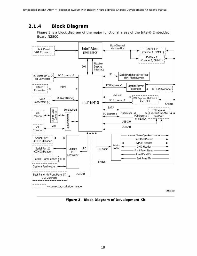
2.1.4 Block Diagram
Figure 3 is a block diagram of the major functional areas of the Intel® Embedded
Board N2800.
Figure 3. Block Diagram of Development Kit

Embedded Intel® Atom™ Processor N2800 with Intel® NM10 Express Chipset Development Kit User‘s Manual
20
2.2 Online Support For information about… Visit this web site:
Intel®
AtomTM Processor N2800 and
NM10 Express Chipset Platform
Overview
http://www.intel.com/p/en_US/embedded/hwsw/hardware/atom
-n2000-d2000/overview
Chipset information http://www.intel.com/products/desktop/chipsets/index.htm
(Search for NM10 Express Chipset)
BIOS and driver updates http://downloadcenter.intel.com
(Search for 'NM10 Express Chipset' & 'N2800')
http://www.intel.com/p/en_US/embedded/hwsw/hardware/atom
-n2000-d2000/software
Tested memory http://www.intel.com/support/motherboards/desktop/sb/CS-
025414.htm
(Search for NM10)
Solid State Drives (SSD) http://ark.intel.com/
(Click on SOLID STATE DRIVES link on the left)
Integration information http://www.intel.com/support/go/buildit
Roadmap information, tools,
software, technical documents
Intel Embedded Design Center:
http://www.intel.com/p/en_US/embedded/hwsw/hardware/atom
-n2000-d2000/hardware
2.3 Supported Operating Systems
The following independent operating systems are supported for this platform:
Operating System - Driver Support
Microsoft Windows* 7 - Intel provides drivers
Microsoft Windows* Embedded Standard 7- Intel provides drivers
Microsoft Windows* XP - Intel provides drivers
Microsoft Windows* Embedded CE 7 - Intel provides drivers
MeeGo* 1.2 - Intel provides drivers
Yocto Project* - Intel provides drivers
Wind River* VxWorks* – Wind River provides drivers
Intel strives to provide customers with a complete development environment supporting
customer applications and operating systems. Any software provided in these development
kits is subject to change without notice.
For the latest information on operating system and BIOS support refer to the Intel
Embedded Design Center: http://www.intel.com/p/en_US/embedded/hwsw/hardware/atom-
n2000-d2000/software
Embedded Intel® Atom™ Processor N2800 with Intel® NM10 Express Chipset Development Kit User‘s Manual
21
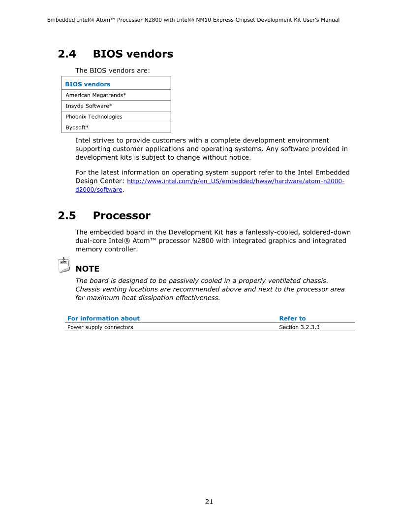
2.4 BIOS vendors
The BIOS vendors are:
BIOS vendors
American Megatrends*
Insyde Software*
Phoenix Technologies
Byosoft*
Intel strives to provide customers with a complete development environment
supporting customer applications and operating systems. Any software provided in
development kits is subject to change without notice.
For the latest information on operating system support refer to the Intel Embedded
Design Center: http://www.intel.com/p/en_US/embedded/hwsw/hardware/atom-n2000-
d2000/software.
2.5 Processor
The embedded board in the Development Kit has a fanlessly-cooled, soldered-down
dual-core Intel® Atom™ processor N2800 with integrated graphics and integrated
memory controller.
NOTE
The board is designed to be passively cooled in a properly ventilated chassis.
Chassis venting locations are recommended above and next to the processor area
for maximum heat dissipation effectiveness.
For information about Refer to
Power supply connectors Section 3.2.3.3

Embedded Intel® Atom™ Processor N2800 with Intel® NM10 Express Chipset Development Kit User‘s Manual
22
2.5.1 Intel® Embedded Board N2800 Graphics Subsystem
2.5.1.1 Intel® Graphics Media Accelerator 3600 Graphics Controller (Intel® GMA)
The Intel® Atom™ Processor N2800 contains an integrated graphics core, the
Intel® GMA 3600 graphics controller, which features the following functionalities:
High quality texture engine
DirectX* 9.0c and OpenGL* 3.0 compliant
Hardware Pixel Shader 4.1
Vertex Shader Model 4.1
640 MHz graphic core frequency 200 MHz render clock frequency Seven display planes, Display Plane A, B, Display Sprite C (can be
connected to either pipe), Display OV (can be connected to either pipe), Cursor A, Cursor B, and VGA
Two display pipes, Pipe A and B support the dual independent displays Max Pixel Clock: SC LVDS: 112 MHz, 18bpp (N2000 series); DDI: 2x 4,
1.62GHz, 2.7GHz; VGA: up to 350MHz Display
Supports VGA displays up to 1920 x 1200 at 60 Hz refresh (WUXGA)
Supports HDMI digital displays up to 1900 x 1200 at 60 Hz refresh rate
and analog (VGA) displays via a converter
Supports LVDS flat panel displays up to 1366 x 768 at 60Hz refresh
Supports Embedded DisplayPort (eDP) flat panel displays up to 1366 x
768 at 60Hz refresh
• Display Ports: eDP/DP x4, HDMI, LVDS (single channel), CRT/DAC Embedded panel: eDP1.1 or LVDS
• External panel: DP1.1, HDMI1.3a, LVDS, CRT/DAC
• Supports HDCP 1.3 & PAVP1.1c (N2800 processor) for Bluray playback
— PAVP: Collection of HW-based security mechanisms designed to
provide a secure path for content from a media player application to the
graphics hardware
— HDCP: Specification developed by Intel Corporation to protect digital
entertainment content across the DVI interface
— Subsequently ported to HDMI and Display Port
• Supports HDMI 1.3a through SW lip-sync • Supports DX*9 • Supports NV12 data format • 3x3 Panel Fitter shared by two pipes • Support Intel® HD Audio Codec • Support Intel® Display Power Saving Technology (Intel® DPST) 4.0 • No Frame Buffer Compensation (FBC) • No TVOut

Embedded Intel® Atom™ Processor N2800 with Intel® NM10 Express Chipset Development Kit User‘s Manual
23
Table 4. Maximum Resolutions Supported by the Intel® Atom™ Processor N2800 with Intel® NM10 Express Chipset Graphic interfaces
Interfaces Max resolution Remark
LVDS (Dual channel) 1366 x 768 60 Hz; 18bpps
eDP 1366 x 768 60 Hz
VGA (CRT/DAC) 1920 x 1200 60 Hz at 267 Mhz Max
HDMI 1920 x 1200 60 Hz; up to 165 MHz
2.5.1.2 Video
The Intel® Atom™ Processor N2800 supports the following video output functionalities
over its display interfaces:
• The Intel® Atom™ Processor N2000 series supports full MPEG2 (VLD/
iDCT/MC), WMV, Fast video Composing, HW decode/ acceleration for MPEG4
Part 10 (AVC/H.264) & VC-1; 720p60, 1080i60, 1080p@24 up to 20 Mps
• MPEG4 part2 does not utilize Next Generation Intel® Atom™ Processor based
Platform H/W
• No hardware assist for Flash Decode from Adobe 11.0 and onwards
• D2700 processor supports Blu-Ray* 2.0 playback (Windows* only) - 1 x HD
and 1 x SD streaming
• Video image Enhancement: Hue, Saturation, Brightness, Contrast (HSBC)
adjust, Bob De-Interlacing
Embedded Intel® Atom™ Processor N2800 with Intel® NM10 Express Chipset Development Kit User‘s Manual
24
2.6 System Memory
The board has two 204-pin SO-DIMM sockets and supports the following memory
features:
1.5V DDR3-800 and DDR3-1066 SO-DIMMs with gold-plated contacts
Unbuffered, non-ECC, Raw Card B (1Rx8) and Raw Card-F (2Rx8) SO-DIMMs only
Single-sided or double-sided modules
4 GB maximum total system memory
Serial Presence Detect
DDR3 800 MHz and DDR3 1066 MHz SO-DIMMs (Higher speed SO-DIMMs
supported at 1066 MHz if supported by the memory module.)
When only using one SO-DIMM, DIMM 1 must be used
NOTE
Due to passively-cooled thermal constraints, system memory must have an operating
temperature rating of 85oC.
The board is designed to be passively cooled in a properly ventilated chassis. Chassis
venting locations are recommended above the system memory area for maximum heat
dissipation effectiveness.
NOTE
To be fully compliant with all applicable DDR3 SDRAM memory specifications, the
board should be populated with SO-DIMMs that support the Serial Presence Detect
(SPD) data structure. This allows the BIOS to read the SPD data and program the
chipset to accurately configure memory settings for optimum performance. If non-SPD
memory is installed, the BIOS will attempt to correctly configure the memory settings,
but performance and reliability may be impacted or the SO-DIMMs may not function
under the determined frequency.

Embedded Intel® Atom™ Processor N2800 with Intel® NM10 Express Chipset Development Kit User‘s Manual
25
Table 5 lists the supported SO-DIMM configurations.
Table 5. Supported Memory Configurations
Raw Card
Version
SO-DIMM
Capacity
DRAM Device
Technology
DRAM
Organization
# of DRAM
Devices
B 1 GB 1 Gb 128 M x 8 8
2 GB 2 Gb 256 M x 8 8
F 2 GB 1 Gb 128 M x 8 16
4 GB 2 Gb 256 M x 8 16
Notes:
1. System memory configurations are based on availability and are subject to change.
2. Support for one 4 GB SO-DIMM installed in slot 1. Slot 0 must be left empty.

Embedded Intel® Atom™ Processor N2800 with Intel® NM10 Express Chipset Development Kit User‘s Manual
26
Figure 4 illustrates the SO-DIMM locations.
Figure 4. SO-DIMM Configuration

Embedded Intel® Atom™ Processor N2800 with Intel® NM10 Express Chipset Development Kit User‘s Manual
27
2.7 Intel® NM10 Express Chipset
The Intel® NM10 Express Chipset with Direct Media Interface (DMI) interconnect
provides interfaces to the processor and the USB, SATA, LPC, LAN, and PCI Express
interfaces. The Intel NM10 Express Chipset is a centralized controller for the board‘s
I/O paths.
For information about Refer to
The Intel NM10 chipset http://www.intel.com/products/desktop/chipsets/index.htm
In Find Content field, enter ―NM10‖
Resources used by the chipset Section 2.1.4
2.8 Graphics Subsystem
The board supports graphics through Intel Graphics Technology.
2.8.1 Integrated Graphics
The board supports integrated graphics through the Intel® Flexible Display Interface
(Intel® FDI) for processors with Intel Graphics Technology.
NOTE
The board can simultaneously support up to two of these three integrated graphics
interfaces: VGA, HDMI, and Flat Panel Display.
Flat Panel Display is supported by eDP and LVDS interfaces, however only one can be
used at a time.
2.8.1.1 Video Memory Allocation
Intel® Dynamic Video Memory Technology (DVMT) is a method for dynamically
allocating system memory for use as graphics memory to balance 2D/3D graphics and
system performance. If your computer is configured to use DVMT, graphics memory is
allocated based on system requirements and application demands (up to the
configured maximum amount). When memory is no longer needed by an application,
the dynamically allocated portion of memory is returned to the operating system for
other uses.
Dynamic allocation of system memory to video memory is as follows:
256 MB total RAM results in 32 MB video RAM
512 MB total RAM results in 64 MB video RAM
1 GB total RAM results in 128 MB video RAM
2 GB total RAM results in 224 MB video RAM

Embedded Intel® Atom™ Processor N2800 with Intel® NM10 Express Chipset Development Kit User‘s Manual
28
2.8.1.2 High Definition Multimedia Interface* (HDMI*)
The HDMI port supports standard, enhanced, or high definition video, plus multi-
channel digital audio on a single cable. It is compatible with all ATSC and DVB HDTV
standards and supports eight full range channels at 24-bit/96 kHz audio. The
maximum supported resolution is 1920 x 1200 (WUXGA). The HDMI port is compliant
with the HDMI 1.3a specification.
Depending on the type of add-in card installed in the PCI Express x1 connector, the
HDMI port will behave as described in Table 6.
Table 6. HDMI Port Status Conditions
PCI Express x1 Connector Status HDMI Port Status
No add-in card installed Enabled
Non-video PCI Express x1 add-in card installed Enabled
Video PCI Express x1 add-in card installed Disabled
2.8.1.3 Analog Display (VGA)
The VGA port supports analog displays. The maximum supported resolution is 1920 x
1200 (WUXGA) at a 60 Hz refresh rate.

Embedded Intel® Atom™ Processor N2800 with Intel® NM10 Express Chipset Development Kit User‘s Manual
29
2.8.2 Flat Panel Display Interfaces
The Kit supports flat panel display via the LVDS and Embedded DisplayPort interfaces.
Figure 5 shows the flat panel connectors.
Item Description
A Backlight inverter voltage selection header
B Flat panel voltage selection header
C FPD brightness connector
D LVDS connector
E Embedded DisplayPort connector
Figure 5. Flat Panel Connectors

Embedded Intel® Atom™ Processor N2800 with Intel® NM10 Express Chipset Development Kit User‘s Manual
30
2.8.2.1 LVDS Interface
The LVDS flat panel display interface supports the following:
1366 x 768 @ 60 Hz resolution
Single-channel and dual-channel interface, up to 135 MHz clock rate 18 bpp and
24 bpp (VESA* and JEIDA mappings) color depth support
Multiple EDID data source capability (panel, predefined, and custom payloads)
3.3 V, 5 V, and 12 V flat panel display voltage flexibility, with up to 3 A current
5V, 12 V and Vin backlight inverter voltage flexibility, with up to 3 A current
Backlight inverter signal redundancy on dedicated header as well as on LVDS
connector (for discrete inverter or panel-integrated inverter support using a single
cable)
Flat panel brightness control via front panel button input as well as Windows* 7
―Screen brightness‖ adjustment slider
Spread-spectrum control
NOTE
Backlight inverter voltage option “Vin” refers to board input voltage as provided to
board power input connector.
NOTE
Support for flat panel display configuration complies with the following:
1. Internal flat panel display settings are not exposed through Intel® Integrator
Toolkit or Intel® Integrator Assistant GUIs.
2. Internal flat panel display settings will not be overwritten by loading BIOS setup
defaults.
3. Internal flat panel display settings will be preserved across BIOS updates.
2.8.2.2 Embedded DisplayPort (eDP) Interface
The eDP (Embedded DisplayPort) flat panel display interface supports the following:
1366 x 768 @ 60 Hz resolution
1-lane, 2-lane, and 4-lane bandwidth at 1.62 Gb/s or 2.7 Gb/s
Multiple EDID data source capability (panel, predefined, and custom payloads)
3.3 V, 5 V, and 12 V flat panel display voltage flexibility, with up to 3 A current
5V, 12 V and Vin backlight inverter voltage flexibility, with up to 3 A current
Backlight inverter signal redundancy on a dedicated header as well as on eDP
connector (for discrete inverter or panel-integrated inverter support using a single
cable)
Flat panel brightness control via front panel button input as well as Windows 7
―Screen brightness‖ adjustment slider

Embedded Intel® Atom™ Processor N2800 with Intel® NM10 Express Chipset Development Kit User‘s Manual
31
NOTE
Backlight inverter voltage option “Vin” refers to board input voltage as provided to
board power input connector.
2.8.2.3 Configuration Modes
Video mode configuration for eDP/LVDS displays is supported as follows:
Automatic panel identification via Extended Display Identification Data (EDID) for
panels with onboard EDID support
Panel selection from common predefined panel types (without onboard EDID)
Custom EDID payload installation for ultimate parameter flexibility, allowing
custom definition of EDID data on panels without onboard EDID
In addition, BIOS setup provides the following configuration parameters for internal
flat panel displays:
Screen Brightness: allows the end user to set the screen brightness for the display
effective through the Power-On Self Test stage (such as while showing the splash
screen image and BIOS setup). Windows 7 ignores this setting in favor of the
native ―screen brightness‖ control provided by the operating system.
Flat Panel Configuration Changes Lock: allows the system integrator to ―lock‖
critical settings of the LVDS configuration to avoid end users potentially rendering
the display unusable.
Brightness Steps: allows the system integrator to configure the brightness steps for
the operating system‘s ―screen brightness‖ control (such as the ―Screen brightness‖
adjustment slider under the Windows 7 ―Power Options‖ control panel).
LVDS Interface Type: allows the system integrator to select whether the LVDS
panel is a single-channel or dual-channel display.
Swap LVDS Channels 0/1: allows the system integrator to swap the EVEN/ODD
LVDS channel assignments shall the cable be wired opposite the panel pinout.
Color Depth: allows the system integrator to select whether the panel is 24 bpp
with VESA color mapping (eDP and LVDS), 24 bpp with JEIDA color mapping (LVDS
only), or 18 bpp (eDP and LVDS).
eDP Interface Type: allows the system integrator to select whether the eDP panel is
a 1-lane, 2-lane, or 4-lane display.
eDP Data Rate: allows the system integrator to select whether the eDP panel runs
at 1.62 Gb/s or 2.7 Gb/s.
Inverter Frequency and Polarity: allows the system integrator to set the operating
frequency and polarity of the panel inverter board.
Maximum and Minimum Inverter Current Limit (%): allows the system integrator to
set maximum PWM%, as appropriate, according to the power requirements of the
internal flat panel display and the selected inverter board.
Panel Power Sequencing: allows the system integrator to adjust panel sequencing
parameters, if necessary.
LVDS Spread Spectrum Control: allows the system integrator to adjust spread
spectrum for the LVDS interface.

Embedded Intel® Atom™ Processor N2800 with Intel® NM10 Express Chipset Development Kit User‘s Manual
32
NOTE
Support for flat panel display configuration complies with the following:
1. Internal flat panel display connectivity is disabled (and all parameters hidden) by
default.
2. Internal flat panel display settings are not exposed through Intel® Integrator
Toolkit or Intel® Integrator Assistant GUIs.
3. Internal flat panel display settings will not be overwritten by loading BIOS setup
defaults.
4. Internal flat panel display settings will be preserved across BIOS updates.
2.8.2.4 Multiple Display Configurations under Microsoft* Windows* 7
Microsoft* Windows* 7 operating systems support multi-monitor display. Since the
Intel® Atom™ Processor N2000 series has several display ports available for its two
pipes, it can support up to two different images on different display devices.
Timings and resolutions for these two images may be different. The Intel® Atom™
Processor N2000 series supports Dual Display Clone and Extended Desktop.
Dual Display Clone uses both display pipes to drive the same content, at the same
resolution and color depth to two different displays. This configuration allows for
different refresh rates on each display.
Extended Desktop uses both display pipes to drive different content, at potentially
different resolutions, refresh rates, and color depths to two different displays. This
configuration allows for a larger Windows Desktop by utilizing both displays as a work
surface.

Embedded Intel® Atom™ Processor N2800 with Intel® NM10 Express Chipset Development Kit User‘s Manual
33
2.8.3 USB
The Kit supports up to ten USB ports. The port arrangement is as follows:
Four front panel ports (via two internal headers; one header supports an Intel®
Z-U130 USB Solid-State Drive (or compatible SSD))
Two ports are implemented with stacked back panel connectors (black)
Two high-current/fast-charging ports are implemented through stacked back panel
connectors (yellow)
One port implemented in the PCI Express Half–Mini Card slot
One port implemented in the PCI Express Full-/Half-Mini Card slot
The USB controller on the Intel NM10 Express Chipset provides a direct logical
connection to the USB ports on the back panel as well as on the PCI Express Mini Card
slots, and an indirect connection (through onboard USB hub) to the internal USB
headers. All ten USB ports are high-speed, full-speed, and low-speed capable.
NOTE
Computer systems that have an unshielded cable attached to a USB port may not meet
FCC Class B requirements, even if no device is attached to the cable. Use a shielded
cable that meets the requirements for full-speed devices.
For information about Refer to
The location of the USB connectors on the back panel Figure 12
The location of the front panel USB headers Figure 13

Embedded Intel® Atom™ Processor N2800 with Intel® NM10 Express Chipset Development Kit User‘s Manual
34
2.9 SATA Interfaces
The Kit provides two SATA ports through the Intel® NM10 Express Chipset PCH
(Platform Controller Hub), which supports one device per port:
One internal SATA connector (black)
One internal SATA connector (multiplexed with mSATA port, routed to PCI Express
Full-/Half-Mini Card slot) (gray)
The PCH provides independent SATA ports with a theoretical maximum transfer rate of
3 Gb/s. A point-to-point interface is used for host to device connections.
The underlying SATA functionality is transparent to the operating system. The SATA
controller can operate in both legacy and native modes. In legacy mode, standard IDE
I/O and IRQ resources are assigned (IRQ 14 and 15). In Native mode, standard PCI
Conventional bus resource steering is used. Native mode is the preferred mode for
configurations using Windows operating systems.
The board has an internal SATA power connector and ships with a power cable for
powering internal SATA storage devices. The power cable includes:
Right-angled 15-pin SATA female connector (for motherboard connectivity)
1 x 4 Molex female connector (for slim optical drive adapter connectivity)
15-pin SATA female connector (for storage connectivity)
Vertical 15-pin SATA female connector (for storage connectivity)
NOTE
Board power supplied through the SATA power connector is rated at a maximum of:
1.0 A from 12 V rail
2.5 A from 5 V rail
0.5 A from 3.3 V rail
For information about Refer to
The location of the SATA connectors Figure 13
2.9.1 AHCI Mode
The board supports AHCI storage mode via the Intel NM10 Express Chipset.
NOTE
In order to use AHCI mode, AHCI must be enabled in the BIOS. Microsoft Windows 7
includes the necessary AHCI drivers without the need to install separate AHCI drivers
during the operating system installation process, however, it is always good practice to
update the AHCI drivers to the latest available release.

Embedded Intel® Atom™ Processor N2800 with Intel® NM10 Express Chipset Development Kit User‘s Manual
35
2.10 Real-Time Clock Subsystem
A coin-cell battery (CR2032) powers the real-time clock and CMOS memory. When the
computer is not plugged into a wall socket, the battery has an estimated life of three
years. When the computer is plugged in, the standby current from the power supply
extends the life of the battery. The clock is accurate to 13 minutes/year at 25 ºC
with 3.3 VSB applied via the power supply 5 V STBY rail.
NOTE
If the battery and AC power fail, date and time values will be reset and the user will be
notified during the POST.
When the voltage drops below a certain level, the BIOS Setup program settings stored
in CMOS RAM (for example, the date and time) might not be accurate. Replace the
battery with an equivalent one. Figure 1 shows the location of the battery.
2.11 Legacy I/O Controller The I/O controller provides the following features:
Two serial port headers
One parallel port header with output only, bi-directional and Enhanced Parallel Port
(EPP) support
Serial IRQ interface compatible with serialized IRQ support for PCI systems
Intelligent power management, including a programmable wake-up event interface
PS/2-style keyboard and mouse interfaces
PS/2 ports are NOT exposed by the N2800-based Development Kit
Conventional PCI bus power management support
The BIOS Setup program provides configuration options for the I/O controller.
2.11.1 Serial Ports
The serial ports, are implemented as two 10-pin headers on the board. The serial
ports support data transfers at speeds up to 115.2 kbits/sec with BIOS support.
For information about Refer to
The location of the serial port headers Figure 13

Embedded Intel® Atom™ Processor N2800 with Intel® NM10 Express Chipset Development Kit User‘s Manual
36
2.11.2 Parallel Port
The parallel port is implemented as a 26-pin header on the board. Use the BIOS Setup
program to set the parallel port mode.
For information about Refer to
The location of the parallel port header Figure 13

Embedded Intel® Atom™ Processor N2800 with Intel® NM10 Express Chipset Development Kit User‘s Manual
37
2.12 Audio Subsystem
The board supports Intel® High Definition Audio (Intel® HD Audio) subsystem via the
Realtek ALC888S audio codec and the HDMI interface. The audio subsystem supports
the following features:
Analog line-out (back panel jack)
Analog line-in (back panel jack)
In-chassis stereo speakers support (3 W/3 via internal header)
Signal-to-noise ratios (SNR) of 97 dB for the DACs and 90 dB for the ADCs
Support for 44.1 kHz/48 kHz/96 kHz/192 kHz sample rates on all analog outputs
Support for 44.1 kHz/48 kHz/96 kHz sample rates on all analog inputs
S/PDIF digital audio output (internal header)
Support for 44.1 kHz/48 kHz/88.2 kHz/96 kHz/192 kHz sample rates at 16-bit, 20-
bit or 24-bit resolution on SPDIF outputs
DMIC interface (internal header), with support for mono and stereo digital
microphones
Front panel HD Audio/AC‘97 headphones/microphone support (internal header)
Advanced jack sense for the back panel line-out jack that enables the audio codec
to recognize the connected device. The back panel audio jacks are capable of
retasking according to the user‘s definition, or can be automatically switched
depending on the recognized device type.
Microphone input jack that supports a single dynamic, condenser, or electret
microphone
Windows 7 Ultimate certification
Table 7 lists the supported functions of the front panel and back panel audio jacks.
Table 7. Audio Jack Support
Audio Jack Microphone Headphones Line Out Line In
FP Green Jack Default
FP Pink Jack Default
Rear Green Jack Jack detect
Rear Pink Jack Default
Internal Stereo Speaker Default

Embedded Intel® Atom™ Processor N2800 with Intel® NM10 Express Chipset Development Kit User‘s Manual
38
2.12.1 Audio Subsystem Software
The latest audio software and drivers are available from Intel‘s World Wide Web site.
For information about Refer to
Obtaining audio software and drivers Section 2.2
2.12.2 Audio Subsystem Components
The audio subsystem includes the following components:
Intel NM10 Express Chipset
Realtek ALC888S audio codec
Two ports for analog line-in and analog line-out on the back panel
Front panel audio header that supports Intel HD audio and AC‘97 audio (a 2 x 5-pin
header that provides microphone in and headphones signals for front panel audio
connectors)
Internal S/PDIF header (1 x 4-pin header)
Internal DMIC header (1 x 5-pin header)
Internal stereo speakers connector (1 x 4-pin, shrouded)
The back panel audio connectors are configurable through the audio device drivers.
The available configurable back panel audio connectors are shown in Figure 6.
Item Description
A Analog line out
B Analog line-in
Figure 6. Back Panel Audio Connectors
NOTE
The analog circuit of the back panel audio line out connector is designed to power
headphones or amplified speakers only. Poor audio quality occurs if passive (non-
amplified) speakers are connected to this output.

Embedded Intel® Atom™ Processor N2800 with Intel® NM10 Express Chipset Development Kit User‘s Manual
39
Figure 7 shows the location of the internal audio headers.
Item Description
A Front panel audio header
B DMIC header
C S/PDIF header
D Internal stereo speakers connector
Figure 7. Internal Audio Headers
For information about Refer to
The signal names of the audio headers Section 3.2.3.1

Embedded Intel® Atom™ Processor N2800 with Intel® NM10 Express Chipset Development Kit User‘s Manual
40
2.13 LAN Subsystem
The LAN subsystem consists of the following:
Intel 82574L Gigabit Ethernet Controller (10/100/1000 Mbits/s)
Intel NM10 Express Chipset
RJ-45 LAN connector with integrated status LEDs
Additional features of the LAN subsystem include:
CSMA/CD protocol engine
LAN connect interface that supports the Ethernet controller
Conventional PCI bus power management
⎯ Supports ACPI technology
⎯ Supports LAN wake capabilities
For information about Refer to
LAN software and drivers http://downloadcenter.intel.com
2.13.1 Intel® 82574L Gigabit Ethernet Controller
The Intel 82574L Gigabit Ethernet Controller supports the following features:
10/100/1000 BASE-T (IEEE 802.3, 802.3u and 802.3ab) compliant
IEEE 802.3ab auto negotiation support
IEEE 802.3x flow control and Auto MDI, MDI-X crossover at all speeds
Full wake-up support (APM and ACPI 2.0) (Magic Packet* wake-up capable)
Smart power down at S0 no link and Sx no link
Jumbo (9kB) frame support
PCI Express power management support
TimeSync offload (IEEE1588 and 802.1as) compliant
Quality of Service (QoS) (802.1p) compliant
VLAN (802.1q) compliant
TCP, IP, and UDP checksum offload (for IPv4 and IPv6)
Transmit TCP segmentation
Full device driver compatibility

Embedded Intel® Atom™ Processor N2800 with Intel® NM10 Express Chipset Development Kit User‘s Manual
41
2.13.2 LAN Subsystem Software & Drivers
LAN software and drivers are available from Intel‘s web site.
For information about Refer to
Obtaining LAN software and drivers http://downloadcenter.intel.com
2.13.3 RJ-45 LAN Connector with Integrated LEDs
Two LEDs are built into the RJ-45 LAN connector (shown in Figure 8).
Item Description
A Link LED (Green)
B Data Rate LED (Green/Yellow)
Figure 8. LAN Connector LED Locations
Table 8 describes the LED states when the board is powered up and the LAN
subsystem is operating.
Table 8. LAN Connector LED States
LED LED Color LED State Condition
Link Green
Off LAN link is not established.
On LAN link is established.
Blinking LAN activity is occurring.
Data Rate Green/Yellow
Off 10 Mbits/s data rate is selected.
Green 100 Mbits/s data rate is selected.
Yellow 1000 Mbits/s data rate is selected.

Embedded Intel® Atom™ Processor N2800 with Intel® NM10 Express Chipset Development Kit User‘s Manual
42
2.14 Hardware Management Subsystem
The hardware management features enable the board to be compatible with the Wired
for Management (WfM) specification. The board has several hardware management
features, including thermal and voltage monitoring.
For information about Refer to
Wired for Management (WfM) Specification www.intel.com/design/archives/wfm/
2.14.1 Hardware Monitoring
The hardware monitoring and fan control subsystem is based on the Nuvoton
W83627DHG device, which supports the following:
Processor and system ambient temperature monitoring
System fan speed monitoring
Voltage monitoring of +12 V, +5 V, +3.3 V, PCH Vcc, Memory Vcc, Processor Vcc
and +3.3V Standby
SMBus interface
2.14.2 Fan Monitoring
Fan monitoring can be implemented using Intel® Desktop Utilities or third-party
software.
For information about Refer to
The functions of the fan header Section 2.15.2.2

Embedded Intel® Atom™ Processor N2800 with Intel® NM10 Express Chipset Development Kit User‘s Manual
43
2.14.3 Thermal Monitoring
Figure 9 shows the locations of the thermal sensor and fan header.
Item Description
A System fan header
B Thermal diode, located on the processor die
Figure 9. Thermal Sensor and Fan Header

Embedded Intel® Atom™ Processor N2800 with Intel® NM10 Express Chipset Development Kit User‘s Manual
44
2.15 Power Management
Power management is implemented at several levels, including:
Software support through Advanced Configuration and Power Interface (ACPI)
Hardware support:
Power connector
Fan header
LAN wake capabilities
Instantly Available PC technology
Wake from USB
Wake from serial port
PCI Express WAKE# signal support
2.15.1 ACPI
ACPI gives the operating system direct control over the power management and Plug
and Play functions of a computer. The use of ACPI with this board requires an
operating system that provides full ACPI support. ACPI features include:
Plug and Play (including bus and device enumeration)
Power management control of individual devices, add-in boards (some add-in
boards may require an ACPI-aware driver), video displays, and hard disk drives
Methods for achieving less than 15-watt system operation in the power-on/standby
sleeping state
A Soft-off feature that enables the operating system to power-off the computer
Support for multiple wake-up events (see Table 11)
Support for a front panel power and sleep mode switch
Table 9 lists the system states based on how long the power switch is pressed,
depending on how ACPI is configured with an ACPI-aware operating system.
Table 9. Effects of Pressing the Power Switch
If the system is in this
state…
…and the power switch is
pressed for
…the system enters this state
Off
(ACPI G2/G5 – Soft off)
Less than four seconds Power-on
(ACPI G0 – working state)
On
(ACPI G0 – working state)
Less than four seconds Soft-off/Standby
(ACPI G1 – sleeping state) Note
On
(ACPI G0 – working state)
More than six seconds Fail safe power-off
(ACPI G2/G5 – Soft off)
Sleep
(ACPI G1 – sleeping state)
Less than four seconds Wake-up
(ACPI G0 – working state)
Sleep
(ACPI G1 – sleeping state)
More than six seconds Power-off
(ACPI G2/G5 – Soft off)
Note: Depending on power management settings in the operating system.
Embedded Intel® Atom™ Processor N2800 with Intel® NM10 Express Chipset Development Kit User‘s Manual
45
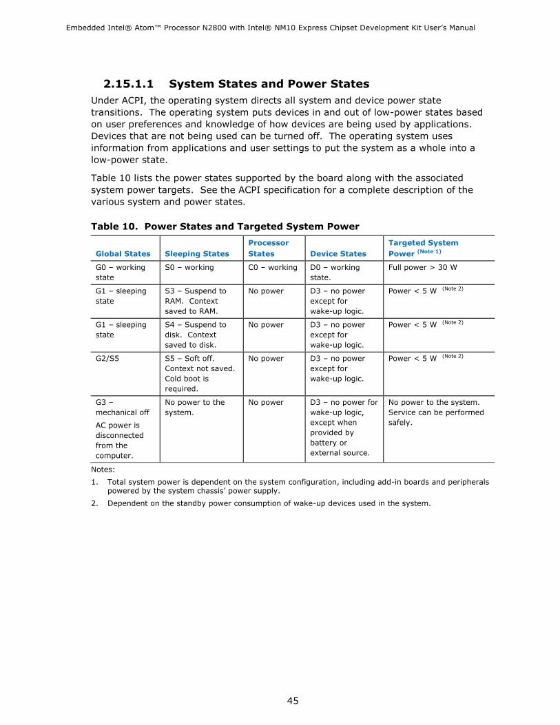
2.15.1.1 System States and Power States
Under ACPI, the operating system directs all system and device power state
transitions. The operating system puts devices in and out of low-power states based
on user preferences and knowledge of how devices are being used by applications.
Devices that are not being used can be turned off. The operating system uses
information from applications and user settings to put the system as a whole into a
low-power state.
Table 10 lists the power states supported by the board along with the associated
system power targets. See the ACPI specification for a complete description of the
various system and power states.
Table 10. Power States and Targeted System Power
Global States
Sleeping States
Processor
States
Device States
Targeted System
Power (Note 1)
G0 – working
state
S0 – working C0 – working D0 – working
state.
Full power > 30 W
G1 – sleeping
state
S3 – Suspend to
RAM. Context
saved to RAM.
No power D3 – no power
except for
wake-up logic.
Power < 5 W (Note 2)
G1 – sleeping
state
S4 – Suspend to
disk. Context
saved to disk.
No power D3 – no power
except for
wake-up logic.
Power < 5 W (Note 2)
G2/S5 S5 – Soft off.
Context not saved.
Cold boot is
required.
No power D3 – no power
except for
wake-up logic.
Power < 5 W (Note 2)
G3 –
mechanical off
AC power is
disconnected
from the
computer.
No power to the
system.
No power D3 – no power for
wake-up logic,
except when
provided by
battery or
external source.
No power to the system.
Service can be performed
safely.
Notes:
1. Total system power is dependent on the system configuration, including add-in boards and peripherals powered by the system chassis‘ power supply.
2. Dependent on the standby power consumption of wake-up devices used in the system.

Embedded Intel® Atom™ Processor N2800 with Intel® NM10 Express Chipset Development Kit User‘s Manual
46
2.15.1.2 Wake-up Devices and Events
Table 11 lists the devices or specific events that can wake the development kit from
specific states.
Table 11. Wake-up Devices and Events
Devices/events that wake up the system… …from this sleep state …from this global state
Power switch S3, S4, S5 (Note 1)
G1, G2, G3
RTC alarm S3, S4, S5 (Note 1)
G1, G2 (Note 3)
LAN S3, S4, S5 (Note 1)
G1, G2 (Note 3)
USB S3 G1
WAKE# S3, S4, S5 (Note 1)
G1, G2 (Note 3)
Serial port S3 G1
Notes:
1. S4 implies operating system support only.
2. Wake from S4 and S5 is recommended by Microsoft.
3. Wake from device/event not supported immediately upon return from AC loss.
NOTE
The use of these wake-up events from an ACPI state requires an operating system that
provides full ACPI support. In addition, software, drivers, and peripherals must fully
support ACPI wake events.
2.15.2 Hardware Support
The board provides several power management hardware features, including:
Instantly Available PC technology
Fan headers
LAN wake capabilities
Wake from USB
WAKE# signal wake-up support
Wake from serial port
Wake from Power Button signal
Standby Power Indicator LED
NOTE
The use of Wake from USB from an ACPI state requires an operating system that
provides full ACPI support.
Embedded Intel® Atom™ Processor N2800 with Intel® NM10 Express Chipset Development Kit User‘s Manual
47
2.15.2.1 Power Input
When resuming from an AC power failure, the computer returns to the power state it
was in before power was interrupted (on or off). The computer‘s response can be set
using the Last Power State feature in the BIOS Setup program‘s Boot menu.
For information about Refer to
The location of the internal power connector Figure 13
The signal names of the internal power connector Table 34
2.15.2.2 Fan Header
The function/operation of the fan header is as follows:
The fan is on when the board is in the S0 state
The fan is off when the board is off or in the S3, S4, or S5 state.
The fan header is wired to a fan tachometer input of the hardware monitoring and
fan control ASIC.
The fan header supports closed-loop fan control that can adjust the fan speed as
needed.
The fan header has a +12 V DC connection.
The fan header supports 3-wire (voltage controlled) fans.
For information about Refer to
The location of the fan header Figure 13
The location of the fan header and sensor for thermal monitoring Figure 9

Embedded Intel® Atom™ Processor N2800 with Intel® NM10 Express Chipset Development Kit User‘s Manual
48
2.15.2.3 LAN Wake Capabilities
LAN wake capabilities enable remote wake-up of the computer through a network. The
LAN subsystem monitors network traffic at the Media Independent Interface. Upon
detecting a Magic Packet* frame, the LAN subsystem asserts a wake-up signal that
powers up the development kit.
2.15.2.4 Instantly Available PC Technology
Instantly Available PC technology enables the board to enter the ACPI S3 (Suspend-to-
RAM) sleep-state. While in the S3 sleep-state, the computer will appear to be off (the
power supply is off, and the front panel LED is amber if dual colored, or off if single
colored.) When signaled by a wake-up device or event, the system quickly returns to
its last known wake state. Table 11 lists the devices and events that can wake the
computer from the S3 state.
The use of Instantly Available PC technology requires operating system support and
drivers for any installed PCI Express add-in card.
2.15.2.5 Wake from USB
USB bus activity wakes the computer from an ACPI S3 state.
NOTE
Wake from USB requires the use of a USB peripheral that supports Wake from USB.
2.15.2.6 WAKE# Signal Wake-up Support
When the WAKE# signal on the PCI Express bus is asserted, the computer wakes from
an ACPI S3, S4, or S5 state.
2.15.2.7 Wake from Serial Port
Serial Port activity wakes the computer from an ACPI S3 state.
2.15.2.8 Wake from S5
When the RTC Date and Time is set in the BIOS, the computer will automatically wake
from an ACPI S5 state.

Embedded Intel® Atom™ Processor N2800 with Intel® NM10 Express Chipset Development Kit User‘s Manual
49
2.15.2.9 Standby Power Indicator LED
The standby power indicator LED shows that power is still present even when the
computer appears to be off. Figure 10 shows the location of the standby power LED.
CAUTION
If AC power has been switched off and the standby power indicator is still lit,
disconnect the power cord before installing or removing any devices connected to the
board. Failure to do so could damage the board and any attached devices.
Figure 10. Location of the Standby Power LED
2.16 Debug Interfaces
The following debug support is provided on the Intel Embedded Board N2800:
XDP (Extended Debug Port) connector supporting 3.3V JTAG is provided at J20 (on the reverse side of the board) for processor run control debug support.
The 10-pin serial ports provide UART connectivity (see Section 2.8.1)

Embedded Intel® Atom™ Processor N2800 with Intel® NM10 Express Chipset Development Kit User‘s Manual
50
3 Technical Reference
3.1 Memory Resources
3.1.1 Addressable Memory
The board utilizes 4 GB of addressable system memory. Typically the address space
that is allocated for PCI Conventional bus add-in cards, PCI Express configuration
space, BIOS (SPI Flash device), and chipset overhead resides above the top of DRAM
(total system memory). On a system that has 4 GB of system memory installed, it is
not possible to use all of the installed memory due to system address space being
allocated for other system critical functions. These functions include the following:
BIOS/SPI Flash device (2 Mbit)
Local APIC (19 MB)
Direct Media Interface (40 MB)
PCI Express configuration space (256 MB)
PCH base address registers
PCI Express ports (up to 256 MB)
Memory-mapped I/O that is dynamically allocated for PCI Express add-in cards
(256 MB)
The board provides the capability to reclaim the physical memory overlapped by the
memory mapped I/O logical address space. The board remaps physical memory from
the top of usable DRAM boundary to the 4 GB boundary to an equivalent sized logical
address range located just above the 4 GB boundary. Figure 11 shows a schematic of
the system memory map. All installed system memory can be used when there is no
overlap of system addresses.

Embedded Intel® Atom™ Processor N2800 with Intel® NM10 Express Chipset Development Kit User‘s Manual
51
Figure 11. Detailed System Memory Address Map

Embedded Intel® Atom™ Processor N2800 with Intel® NM10 Express Chipset Development Kit User‘s Manual
52
3.1.2 Memory Map
Table 12 lists the system memory map.
Table 12. System Memory Map
Address Range
(decimal)
Address Range
(hex)
Size
Description
1024 K - 4194304 K 100000 - FFFFFFFF 4095 MB Extended memory
960 K - 1024 K F0000 - FFFFF 64 KB Runtime BIOS
896 K - 960 K E0000 - EFFFF 64 KB Reserved
800 K - 896 K C8000 - DFFFF 96 KB Potential available high DOS
memory (open to the PCI bus).
Dependent on video adapter used.
640 K - 800 K A0000 - C7FFF 160 KB Video memory and BIOS
639 K - 640 K 9FC00 - 9FFFF 1 KB Extended BIOS data (movable by
memory manager software)
512 K - 639 K 80000 - 9FBFF 127 KB Extended conventional memory
0 K - 512 K 00000 - 7FFFF 512 KB Conventional memory
3.2 Connectors and Headers
CAUTION
Only the following connectors and headers have overcurrent protection: back panel and front panel USB.
The other internal connectors and headers are not overcurrent protected and should connect only to devices inside the computer’s chassis, such as fans and internal peripherals. Do not use these connectors or headers to power devices external to the computer’s chassis. A fault in the load presented by the external devices could cause damage to the computer, the power cable, and the external devices themselves.
Furthermore, improper connection of USB header single wire connectors may eventually overload the overcurrent protection and cause damage to the board.
This section describes the board‘s connectors and headers. The connectors and
headers can be divided into these groups:
Back panel I/O connectors
On-board I/O connectors and headers
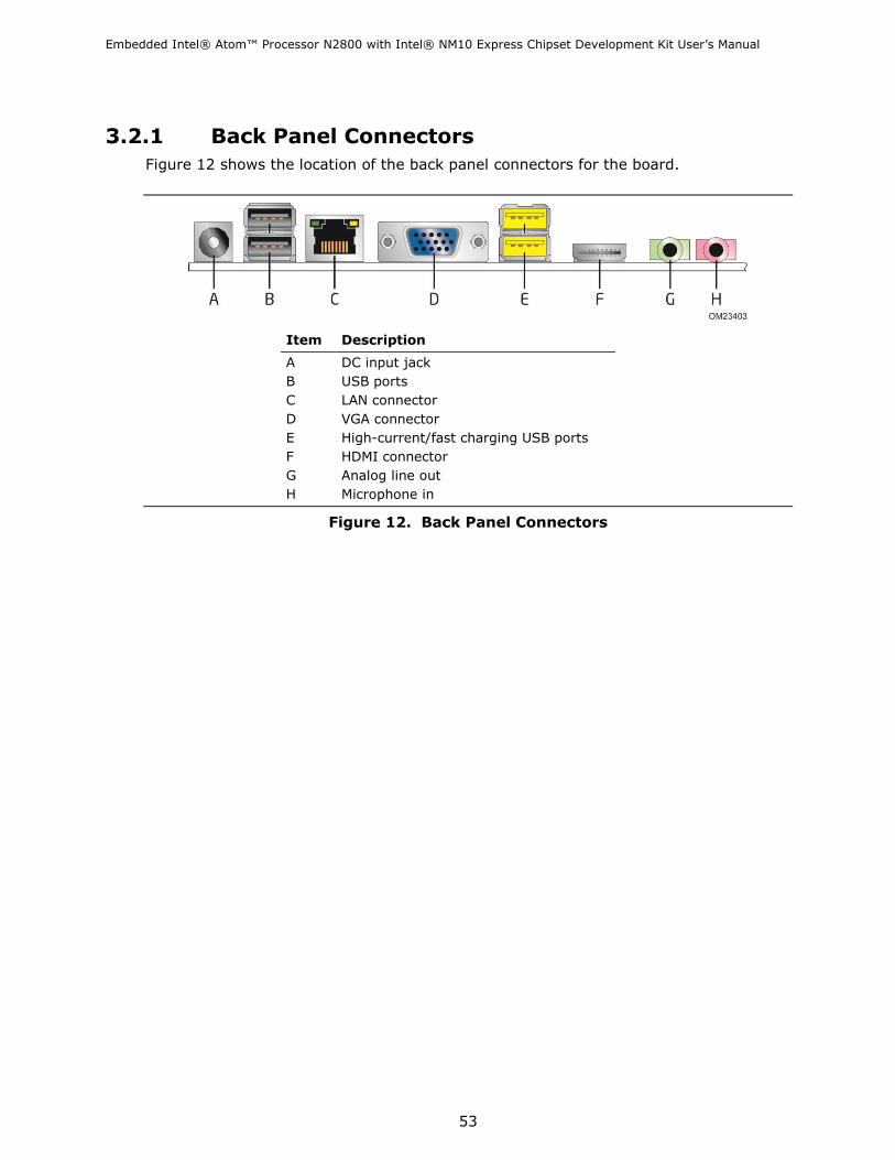
Embedded Intel® Atom™ Processor N2800 with Intel® NM10 Express Chipset Development Kit User‘s Manual
53
3.2.1 Back Panel Connectors
Figure 12 shows the location of the back panel connectors for the board.
Item Description
A DC input jack
B USB ports
C LAN connector
D VGA connector
E High-current/fast charging USB ports
F HDMI connector
G Analog line out
H Microphone in
Figure 12. Back Panel Connectors

Embedded Intel® Atom™ Processor N2800 with Intel® NM10 Express Chipset Development Kit User‘s Manual
54
3.2.2 Connectors and Headers (Top)
Figure 13 shows the locations of the connectors and headers on the top-side of the
board.
Figure 13. Connectors and Headers (Top)

Embedded Intel® Atom™ Processor N2800 with Intel® NM10 Express Chipset Development Kit User‘s Manual
55
Table 13 lists the connectors and headers identified in Figure 13.
Table 13. Connectors and Headers Shown in Figure 13
Item/callout
from Figure 13
Description
Connector Information
Board Connector Mating Plug
A Debug connector 1x11, 1.25mm-pitch
B System fan header 3-wire fan
C Internal power connector Molex* 5566-2 Molex 5557-02R
D SATA data connector 7-pin SATA (male) 7-pin SATA (female)
E SATA power connector 15-pin SATA (male) 15-pin SATA (female)
F PCI Express Half-Mini Card slot
G SATA data connector 7-pin SATA (male) 7-pin SATA (female)
H LVDS connector ACES* 88341-40 ACES 88441-40
Starconn* 107F40
I FPD brightness connector Foxconn* HF5508 JWT* A2001H02-8P
J Flat panel voltage selection header 2x3, 2.54mm-pitch Jumper
K Backlight inverter voltage selection
header
2x3, 2.54mm-pitch Jumper
L Front panel header 2x5, 2.54mm-pitch
M Front panel audio header 2x5, 2.54mm-pitch
N Front panel dual-port USB header 2x5, 2.54mm-pitch
O Front panel dual-port USB header 2x5, 2.54mm-pitch
P Serial port header 2x5, 2.54mm-pitch
Q Serial port header 2x5, 2.54mm-pitch
R Parallel port header 2x13, 2.54mm-pitch
S DMIC header 1x5, 2.54mm-pitch
T PCI Express Full-/Half-Mini Card slot
U Custom Solutions header 2x4, 2.00mm-pitch
V PCI Express 1.0a x1 connector
W S/PDIF header 1x4, 2.54mm-pitch
X Internal stereo speakers header JS*-1125-04 JWT* A2001H02-4P

Embedded Intel® Atom™ Processor N2800 with Intel® NM10 Express Chipset Development Kit User‘s Manual
56
3.2.3 Connectors and Headers (Bottom)
Figure 14 shows the locations of the connectors and headers on the bottom-side of the
board.
Figure 14. Connectors and Headers (Bottom)
Table 14 lists the connectors and headers identified in Figure 14.
Table 14. Connectors and Headers Shown in Figure 14
Item/callout
from Figure 14
Description
Connector Information
Board Connector Mating Plug
A eDP connector ACES 50203-040 ACES 88441-40
Starconn 107F40

Embedded Intel® Atom™ Processor N2800 with Intel® NM10 Express Chipset Development Kit User‘s Manual
57
3.2.3.1 Signal Tables for the Connectors and Headers
Table 15. Front Panel Audio Header for Intel HD Audio
Pin Signal Name Description
1 PORT_1L Analog Port 1 – Left channel (Microphone)
2 GND Ground
3 PORT_1R Analog Port 1 – Right channel (Microphone)
4 PRESENCE# Active low signal that signals BIOS that an Intel HD Audio
dongle is connected to the analog header. PRESENCE#=0
when an Intel HD Audio dongle is connected
5 PORT_2R Analog Port 2 – Right channel (Headphone)
6 SENSE1_RETURN Jack detection return for front panel (JACK1)
7 SENSE_SEND Jack detection sense line from the Intel HD Audio CODEC
jack detection resistor network
8 KEY No pin
9 PORT_2L Analog Port 2 – Left channel (Headphone)
10 SENSE2_RETURN Jack detection return for front panel (JACK2)
Table 16. Front Panel Audio Header for AC’97 Audio
Pin Signal Name Description
1 MIC Front panel microphone input signal (biased when
supporting stereo microphone)
2 AUD_GND Ground used by analog audio circuits
3 MIC_BIAS Microphone power / additional MIC input for stereo
microphone support
4 PRESENCE# Active low signal that signals BIOS that an Intel HD Audio
dongle is connected to the analog header. PRESENCE#=0
when an Intel HD Audio dongle is connected
5 FP_OUT_R Right channel audio signal to front panel (headphone drive
capable)
6 AUD_GND Ground used by analog audio circuits
7 RESERVED Reserved
8 KEY No pin
9 FP_OUT_L Left channel audio signal to front panel (headphone drive
capable)
10 AUD_GND Ground used by analog audio circuits

Embedded Intel® Atom™ Processor N2800 with Intel® NM10 Express Chipset Development Kit User‘s Manual
58
Table 17. Internal Stereo Speakers Header
Pin Signal Name Description
1 Front_L− Analog front left (differential negative)
2 Front_L+ Analog front left (differential positive)
3 Front_R+ Analog front right (differential positive)
4 Front_R− Analog front right (differential negative)
Table 18. Internal S/PDIF Header
Pin Signal Name Description
1 GND Ground
2 SPDIF_OUT SPDIF signal from the codec
3 Key (no pin) Key (no pin)
4 +5V_DC 5 V power (for optical/TOSLINK module)
Table 19. Internal DMIC Header
Pin Signal Name Description
1 +3.3 V 3.3 V power (for DMIC module)
2 DMIC_DATA DMIC data signal
3 GND Ground
4 DMIC_CLK DMIC clock signal
5 Key (no pin) Key (no pin)
Table 20. Front Panel USB Dual-Port Header
Pin Signal Name Pin Signal Name
1 +5 V DC 2 +5 V DC
3 D− 4 D−
5 D+ 6 D+
7 Ground 8 Ground
9 KEY (no pin) 10 No Connect
Table 21. Front Panel USB Dual-Port Header (with support for Intel Z-U130 USB Solid-State Drive or compatible SSD)
Pin Signal Name Pin Signal Name
1 +5 V DC 2 +5 V DC
3 D− 4 D−
5 D+ 6 D+
7 Ground 8 Ground
9 KEY (no pin) 10 LED#

Embedded Intel® Atom™ Processor N2800 with Intel® NM10 Express Chipset Development Kit User‘s Manual
59
Table 22. Serial Port Headers
Pin Signal Name Pin Signal Name
1 DCD (Data Carrier Detect) 2 RXD# (Receive Data)
3 TXD# (Transmit Data) 4 DTR (Data Terminal Ready)
5 Ground 6 DSR (Data Set Ready)
7 RTS (Request To Send) 8 CTS (Clear To Send)
9 RI (Ring Indicator) 10 Key (no pin)
Table 23. Parallel Port Header
Pin Standard Signal Name EPP Signal Name
1 STROBE# WRITE#
2 AUTOFD# DATASTB#
3 PD0 PD0
4 FAULT# FAULT#
5 PD1 PD1
6 INT# RESET#
7 PD2 PD2
8 SLCTIN# ADDRSTB#
9 PD3 PD3
10 GROUND GROUND
11 PD4 PD4
12 GROUND GROUND
13 PD5 PD5
14 GROUND GROUND
15 PD6 PD6
16 GROUND GROUND
17 PD7 PD7
18 GROUND GROUND
19 ACK# INTR
20 GROUND GROUND
21 BUSY WAIT#
22 GROUND GROUND
23 PERROR PE
24 GROUND GROUND
25 SELECT SELECT
26 KEY (no pin) KEY (no pin)
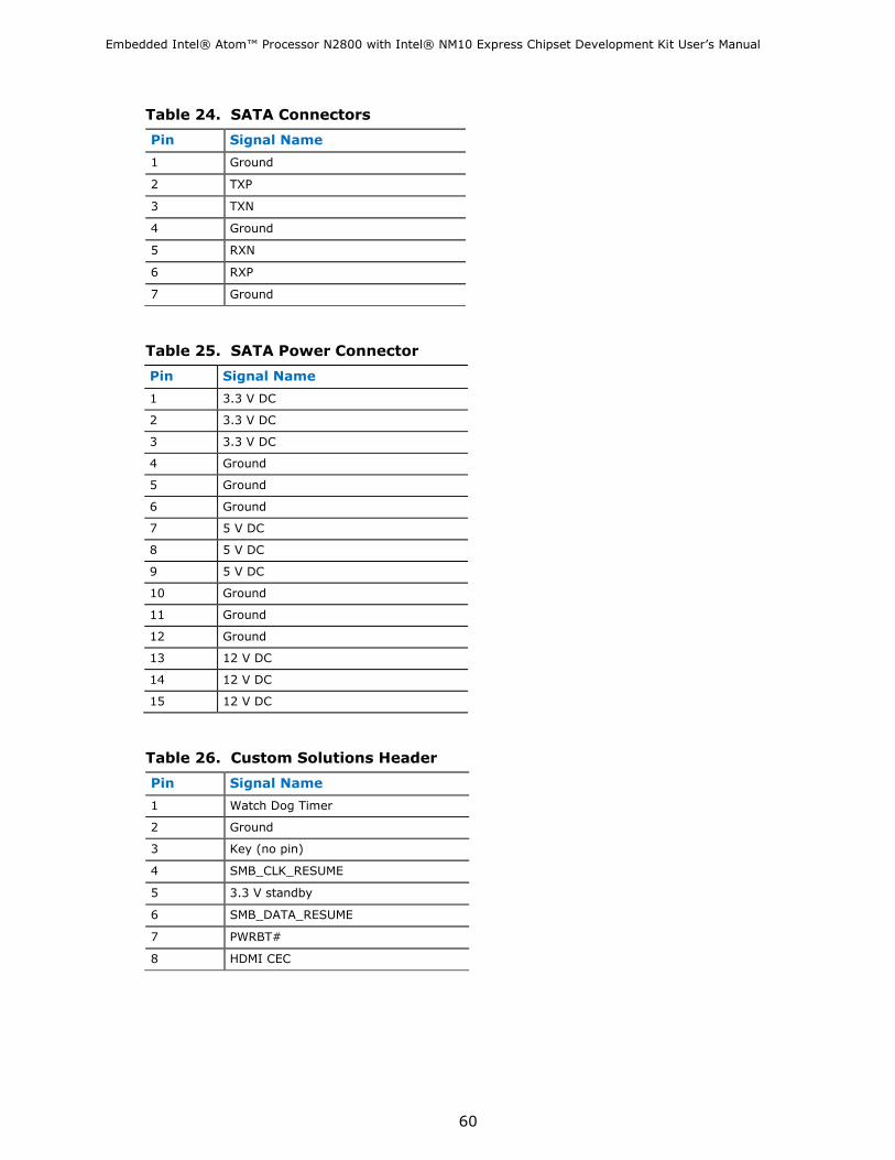
Embedded Intel® Atom™ Processor N2800 with Intel® NM10 Express Chipset Development Kit User‘s Manual
60
Table 24. SATA Connectors
Pin Signal Name
1 Ground
2 TXP
3 TXN
4 Ground
5 RXN
6 RXP
7 Ground
Table 25. SATA Power Connector
Pin Signal Name
1 3.3 V DC
2 3.3 V DC
3 3.3 V DC
4 Ground
5 Ground
6 Ground
7 5 V DC
8 5 V DC
9 5 V DC
10 Ground
11 Ground
12 Ground
13 12 V DC
14 12 V DC
15 12 V DC
Table 26. Custom Solutions Header
Pin Signal Name
1 Watch Dog Timer
2 Ground
3 Key (no pin)
4 SMB_CLK_RESUME
5 3.3 V standby
6 SMB_DATA_RESUME
7 PWRBT#
8 HDMI CEC

Embedded Intel® Atom™ Processor N2800 with Intel® NM10 Express Chipset Development Kit User‘s Manual
61
Table 27. System Fan Header
Pin Signal Name
1 Ground
2 +12 V (PWM controlled pulses)
3 Tach
Table 28. Flat Panel Voltage Selection Header
Pin Signal Name Description
1 Key No pin
2 3.3 V 3.3 V option (default)
3 12 V 12 V option
4 LCD_VCC Send voltage to connector
5 Key No pin
6 5 V 5 V option
Table 29. Backlight Inverter Voltage Selection Header
Pin Signal Name Description
1 Key No pin
2 5 V 5 V option
3 Vin Board input voltage option
4 BKLT_PWR Send voltage to connector
5 Key No pin
6 12 V 12 V option

Embedded Intel® Atom™ Processor N2800 with Intel® NM10 Express Chipset Development Kit User‘s Manual
62
Table 30. 40-Pin LVDS Connector
Pin Signal Name Pin Signal Name
1 ODD_Lane3_P 21 N/C
2 ODD_Lane3_N 22 EDID_3.3 V
3 ODD_Lane2_P 23 LCD_GND
4 ODD_Lane2_N 24 LCD_GND
5 ODD_Lane1_P 25 LCD_GND
6 ODD_Lane1_N 26 ODD_CLK_P
7 ODD_Lane0_P 27 ODD_CLK_N
8 ODD_Lane0_N 28 BKLT_GND
9 EVEN_Lane3_P 29 BKLT_GND
10 EVEN_Lane3_N 30 BKLT_GND
11 EVEN_Lane2_P 31 EDID_CLK
12 EVEN_Lane2_N 32 BKLT_ENABLE
13 EVEN_Lane1_P 33 BKLT_PWM_DIM
14 EVEN_Lane1_N 34 EVEN_CLK_P
15 EVEN_Lane0_P 35 EVEN_CLK_N
16 EVEN_Lane0_N 36 BKLT_PWR
17 EDID_GND 37 BKLT_PWR
18 LCD_VCC 38 BKLT_PWR
19 LCD_VCC 39 N/C
20 LCD_VCC 40 EDID_DATA
NOTE
LVDS single-channel output is driven from the EVEN signals.

Embedded Intel® Atom™ Processor N2800 with Intel® NM10 Express Chipset Development Kit User‘s Manual
63
Table 31. 40-Pin eDP Connector
Pin Signal Name Pin Signal Name
1 NC_Reserved 21 LCD_VCC
2 High-speed_GND 22 LCD_Self_Test-or-NC
3 Lane3_N (DDPD_[3]N) 23 LCD_GND
4 Lane3_P (DDPD_[3]P) 24 LCD_GND
5 High-speed_GND 25 LCD_GND
6 Lane2_N (DDPD_[2]N) 26 LCD_GND
7 Lane2_P (DDPD_[2]P) 27 HPD (DDPD_HPD)
8 High-speed_GND 28 BKLT_GND
9 Lane1_N (DDPD_[1]N) 29 BKLT_GND
10 Lane1_P (DDPD_[1]P) 30 BKLT_GND
11 High-speed_GND 31 BKLT_GND
12 Lane0_N (DDPD_[0]N) 32 BKLT_ENABLE
13 Lane0_P (DDPD_[0]P) 33 BKLT_PWM_DIM
14 High-speed_GND 34 NC_Reserved
15 AUX_CH_P (DDPD_AUXP) 35 NC_Reserved
16 AUX_CH_N (DDPD_AUXN) 36 BKLT_PWR
17 High-speed_GND 37 BKLT_PWR
18 LCD_VCC 38 BKLT_PWR
19 LCD_VCC 39 BKLT_PWR
20 LCD_VCC 40 NC_Reserved
Table 32. 8-Pin FPD Brightness Connector
Pin Signal Name Description
1 BKLT_EN Backlight enable
2 BKLT_PWM Backlight control
3 BKLT_PWR Backlight inverter power
4 BKLT_PWR Backlight inverter power
5 BKLT_GND/Brightness_GND Ground (shared)
6 BKLT_GND/Brightness_GND Ground (shared)
7 Brightness_Up Panel brightness increase
8 Brightness_Down Panel brightness decrease

Embedded Intel® Atom™ Processor N2800 with Intel® NM10 Express Chipset Development Kit User‘s Manual
64
Table 33. PCI Express Full-/Half-Mini Card Connector
Pin Signal Name Additional Signal Name
1 WAKE#
2 +3.3 V aux
3 Reserved
4 GND
5 Reserved
6 1.5 V
7 CLKREQ#
8 Reserved
9 GND
10 Reserved
11 REFCLK-
12 Reserved
13 REFCLK+
14 Reserved
15 GND
16 Reserved
17 Reserved
18 GND
19 Reserved
20 Reserved
21 GND
22 PERST#
23 PERn0
24 +3.3 V aux
25 PERp0
26 GND
27 GND
28 +1.5 V
29 GND
30 SMB_CLK
31 PETn0
32 SMB_DATA
33 PETp0
34 GND
35 GND
36 USB_D-
37 GND (mSATA) GND
38 USB_D+
continued

Embedded Intel® Atom™ Processor N2800 with Intel® NM10 Express Chipset Development Kit User‘s Manual
65
Table 33. PCI Express Full-/Half-Mini Card Connector (continued)
Pin Signal Name Additional Signal Name
39 +3.3 V aux (mSATA) 3.3 V
40 GND
41 +3.3 V aux (mSATA) 3.3 V
42 LED_WWAN#
43 Reserved NC (mSATA indicator)
44 LED_WLAN#
45 Reserved (mSATA) Vendor
46 LED_WPAN#
47 Reserved (mSATA) Vendor
48 +1.5V
49 Reserved (mSATA) DA/DSS
50 GND
51 Reserved (mSATA) Presence Detection
52 +3.3 V aux
3.2.3.2 Add-in Card Connectors
The board has the following add-in card connectors:
One PCI Express 1.0a x1 connector. The x1 interface supports simultaneous
transfer speeds up to 250 MB/s of peak bandwidth per lane, per direction, for up to
500 MB/s concurrent and bi-directional bandwidth.
One PCI Express Half-Mini Card slot
One PCI Express Full-/Half-Mini Card slot (removable stand-offs in full-length keep
out zone allows repurposing of Full-Mini Card slot into Half-Mini Card slot)
3.2.3.3 Power Supply Connectors
This development kit is shipped with a 60W AC/DC switching mode power supply. It is
recommended to use this power supply.
The kit supports a wide-range voltage input that can also be driven by either of the
following alternate power supply types:
External Power Supply – the board can be powered with an 8 - 19 VDC external
power supply though the DC jack on the back panel. This connector accepts dual-
barrel plugs with an inner diameter (ID) of 2.5 mm and an outer diameter (OD) of
5.5 mm, where the inner contact is +8 (±10%) through +19 (±10%) VDC and the
shell is GND. The maximum current rating for this connector is 8 A.
Internal Power Supply – the board can alternatively be powered via the internal
1 x 2 power connector, where pin 1 is GND and pin 2 is +8 (±10%) through +19
(±10%) VDC. The maximum current rating for this connector is 10 A.

Embedded Intel® Atom™ Processor N2800 with Intel® NM10 Express Chipset Development Kit User‘s Manual
66
Table 34. Internal Power Supply Connector Pinout
Pin Signal Name
1 Ground
2 DC input: +8 (±10%) through +19 (±10%) VDC
For information about Refer to
Power supply considerations Section 3.6.1
3.2.3.4 Front Panel Header
This section describes the functions of the front panel header. Table 35 lists the signal
names of the front panel header. Figure 15 is a connection diagram for the front panel
header.
Table 35. Front Panel Header
Pin Signal Name Description Pin Signal Name Description
1 HDD_POWER_LED Pull-up resistor
(750 Ω) to +5V
2 POWER_LED_MAIN [Out] Front panel LED
(main color)
3 HDD_LED# [Out] Hard disk
activity LED
4 POWER_LED_ALT [Out] Front panel LED
(alt color)
5 GROUND Ground 6 POWER_SWITCH# [In] Power switch
7 RESET_SWITCH# [In] Reset switch 8 GROUND Ground
9 +5V_DC Power 10 Key No pin
Figure 15. Connection Diagram for Front Panel Header

Embedded Intel® Atom™ Processor N2800 with Intel® NM10 Express Chipset Development Kit User‘s Manual
67
3.2.3.4.1 Hard Drive Activity LED Header
Pins 1 and 3 of the Front Panel Header can be connected to an LED to provide a visual
indicator that data is being read from or written to a hard drive. Proper LED function
requires a SATA hard drive or optical drive connected to an onboard SATA connector.
3.2.3.4.2 Reset Switch Header
Pins 5 and 7 of the Front Panel Header can be connected to a momentary single pole,
single throw (SPST) type switch that is normally open. When the switch is closed, the
board resets and runs the POST.
3.2.3.4.3 Power/Sleep LED Header
Pins 2 and 4 of the Front Panel Header can be connected to a one- or two-color LED.
Table 36 shows the possible LED states.
Table 36. States for a One-Color Power LED
LED State Description
Off Power off
Blinking Standby
Steady Normal operation
NOTE
The LED behavior shown in Table 36 is default – other patterns may be set via BIOS
setup.
3.2.3.4.4 Power Switch Header
Pins 6 and 8 of the Front Panel Header can be connected to a front panel momentary-
contact power switch. The switch must pull the SW_ON# pin to ground for at least 50
ms to signal the switch on or off. (The time requirement is due to internal debounce
circuitry on the board.) At least two seconds must pass before the board will recognize
another on/off signal.

Embedded Intel® Atom™ Processor N2800 with Intel® NM10 Express Chipset Development Kit User‘s Manual
68
3.2.3.5 Front Panel USB Headers
Figure 16 is a connection diagram for the front panel USB headers.
NOTE The +5 V DC power on the USB headers is fused.
Use only a front panel USB connector that conforms to the USB 2.0 specification for
high-speed USB devices.
Figure 16. Connection Diagram for Front Panel USB Dual-Port Header
Figure 17. Connection Diagram for Front Panel USB Dual-Port Header (with Intel Z-U130 USB Solid-State Drive, or Compatible SSD, Support)
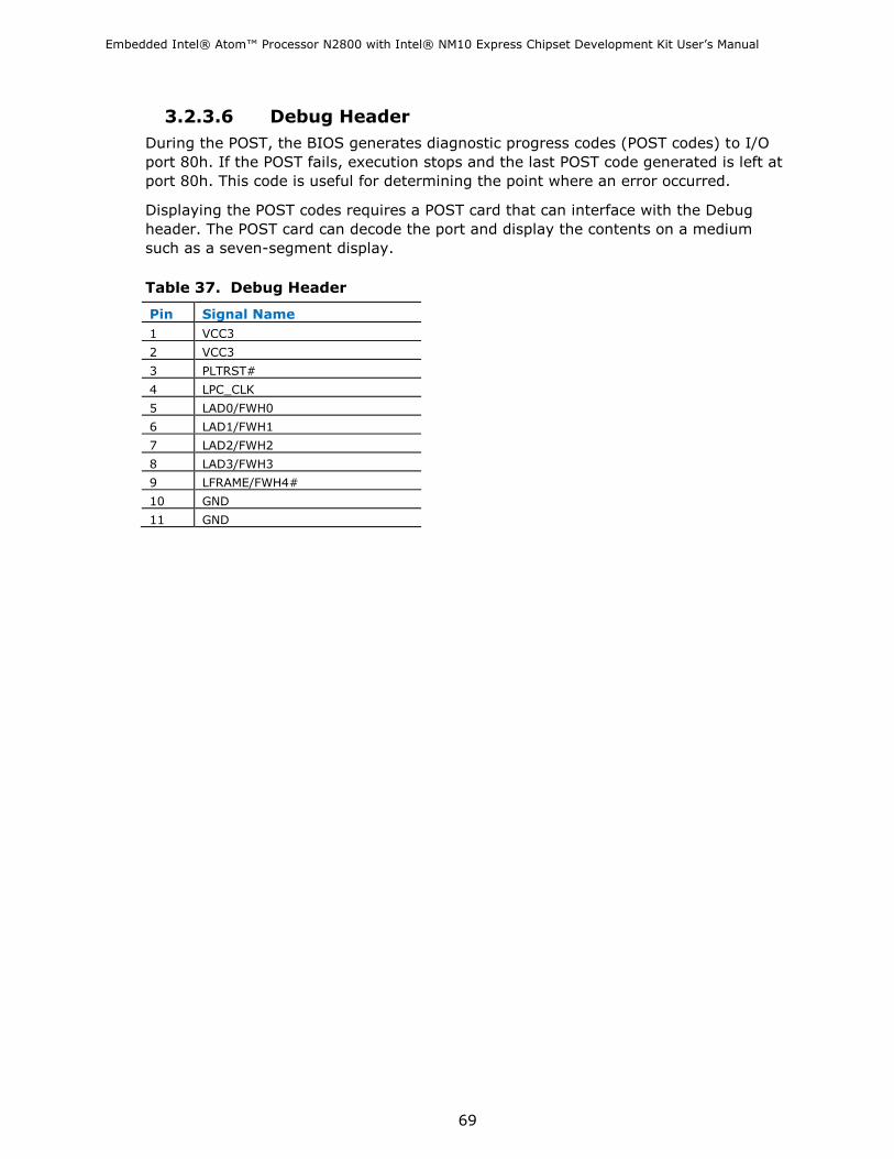
Embedded Intel® Atom™ Processor N2800 with Intel® NM10 Express Chipset Development Kit User‘s Manual
69
3.2.3.6 Debug Header
During the POST, the BIOS generates diagnostic progress codes (POST codes) to I/O
port 80h. If the POST fails, execution stops and the last POST code generated is left at
port 80h. This code is useful for determining the point where an error occurred.
Displaying the POST codes requires a POST card that can interface with the Debug
header. The POST card can decode the port and display the contents on a medium
such as a seven-segment display.
Table 37. Debug Header
Pin Signal Name
1 VCC3
2 VCC3
3 PLTRST#
4 LPC_CLK
5 LAD0/FWH0
6 LAD1/FWH1
7 LAD2/FWH2
8 LAD3/FWH3
9 LFRAME/FWH4#
10 GND
11 GND

Embedded Intel® Atom™ Processor N2800 with Intel® NM10 Express Chipset Development Kit User‘s Manual
70
3.3 I/O Shields When installed in the chassis, the I/O shield blocks radio frequency transmissions, protects internal components from dust and foreign objects, and promotes correct airflow within the chassis.
Two I/O shields are provided inside the chassis to house the embedded board:
Half-height I/O shield
Standard-height I/O shield
The half-height I/O shield allows access to all back panel connectors while being
specifically designed for thin mini-ITX chassis, compliant with version 2.0 of the Mini-
ITX Addendum to the microATX Motherboard Interface Specification.
The standard-height I/O shield provides access to all the same connectors as the half-
height I/O shield while being compatible with standard mini-ITX and microATX chassis.
In addition to the F-type pre-cut hole, the standard-height I/O shield also provides
pre-cut holes for user installation of two external wireless antennas for system
configurations with wireless PCI Express Mini Card solutions.
Figure 18 and Figure 19 are I/O shield reference diagrams.
Figure 18. Half-Height Back Panel I/O Shield

Embedded Intel® Atom™ Processor N2800 with Intel® NM10 Express Chipset Development Kit User‘s Manual
71
Figure 19. Standard-Height Back Panel I/O Shield
For more information about Refer to
Thin mini-ITX form factor http://www.formfactors.org/developer%5Cspecs%5CMini_ITX_
Spec_V2_0.pdf
3.4 Jumper Block
CAUTION
Do not move the jumper with the power on. Always turn off the power and unplug the
power cord from the computer before changing a jumper setting. Otherwise, the board
could be damaged.
Figure 20 shows the location of the jumper block. The 3-pin jumper block determines
the BIOS Setup program‘s mode. Table 38 describes the jumper settings for the three
modes: Normal, Configure, and Recovery. When the jumper is set to Configure mode
and the computer is powered-up, the BIOS compares the processor version and the
microcode version in the BIOS and reports if the two match.

Embedded Intel® Atom™ Processor N2800 with Intel® NM10 Express Chipset Development Kit User‘s Manual
72
Figure 20. Location of the Jumper Block
Table 38. BIOS Setup Configuration Jumper Settings
Function/Mode Jumper Setting Configuration
Normal 1-2 The BIOS uses current configuration information and passwords
for booting.
Configure 2-3 After the POST runs, Setup runs automatically. The maintenance
menu is displayed.
Note that this Configure mode is the only way to clear the
BIOS/CMOS settings. Press F9 (restore defaults) while in
Configure mode to restore the BIOS/CMOS settings to their
default values.
Recovery None The BIOS attempts to recover the BIOS configuration. A
recovery CD or flash drive is required.

Embedded Intel® Atom™ Processor N2800 with Intel® NM10 Express Chipset Development Kit User‘s Manual
73
3.5 Mechanical Considerations
3.5.1 Form Factor
The N2800 embedded board is installed into the Development Kit‘s Mini-ITX form-
factor chassis. Figure 21 illustrates the mechanical form factor of the inside of the
chassis. Dimensions are given in inches [millimeters]. The outer dimensions are 6.7
inches by 6.7 inches [170.18 millimeters by 170.18 millimeters]. Location of the I/O
connectors and mounting holes are in compliance with the ATX specification.
NOTE
The embedded board is designed to have a total height of less than 20 mm from the
underside of the board to the top of its tallest components, including all back panel I/O
ports, internal connectors, installed system memory, and factory-installed thermal
solutions, in compliance with thin mini-ITX requirements per version 2 of the Mini-ITX
Addendum to the microATX Motherboard Interface Specification.
For more information about Refer to
Thin mini-ITX form factor http://www.formfactors.org/developer%5Cspecs%5CMini_ITX_
Spec_V2_0.pdf
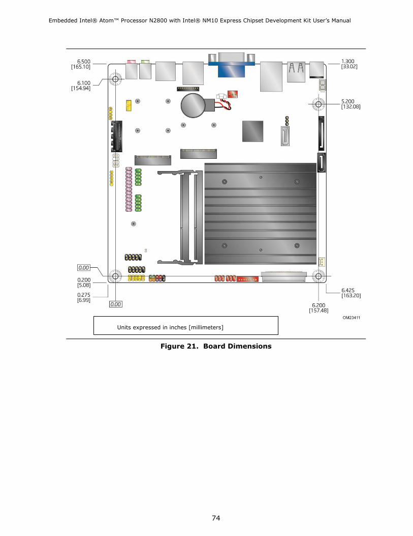
Embedded Intel® Atom™ Processor N2800 with Intel® NM10 Express Chipset Development Kit User‘s Manual
74
Figure 21. Board Dimensions
Units expressed in inches [millimeters]

Embedded Intel® Atom™ Processor N2800 with Intel® NM10 Express Chipset Development Kit User‘s Manual
75
3.6 Electrical Considerations
3.6.1 Power Supply Considerations
CAUTION
The external DC jack is the primary power input connector of Intel Embedded Board
N2800. However, the Embedded Board also provides an internal 1 x 2 power connector
that can be used in custom-developed systems that have an internal power supply.
There is no isolation circuitry between the external DC jack and the internal 1 x 2
power connector. It is the system integrator’s responsibility to ensure no more than
one power supply unit is or can be attached to the board at any time and to ensure the
external DC jack is covered if the internal 1 x 2 power connector is to be used. A
plastic lid for the external DC jack is provided in the accessories box shall it be useful
to the system integrator for this purpose.
Simultaneous connection of both external and internal power supply units could result
in potential damage to the Embedded Board, power supplies, or other hardware.
System power requirements will depend on actual system configurations chosen by the
integrator, as well as end user expansion preferences. It is the system integrator‘s
responsibility to ensure an appropriate power budget for the system configuration is
properly assessed based on the system-level components chosen.

Embedded Intel® Atom™ Processor N2800 with Intel® NM10 Express Chipset Development Kit User‘s Manual
76
3.6.2 Connecting a System Fan & Fan Header Current
Capability
Table 39 lists the current capability of the fan header.
Table 39. Fan Header Current Capability
Fan Header Maximum Available Current
System fan 1.5 A
You can connect a 3-wire system fan cable to the system fan header on the N2800 Embedded Board. Use Figure 22 for guidance.
Figure 22. Location of the Chassis Fan Header
3.6.3 PCI Express* Add-in Card Considerations
The motherboard is designed to provide up to 10 W to the PCI Express x1 slot. The
total power consumption from add-in boards on this slot must not exceed this rating.

Embedded Intel® Atom™ Processor N2800 with Intel® NM10 Express Chipset Development Kit User‘s Manual
77
3.6.3.1 Installing a PCI Express Mini & Full Card in the PCI Express Full-/Half-Mini Card Slot
A PCI Express Full-Mini or Half-Mini Card can be installed in the Embedded Board‘s PCI
Express Full and/or Half-Mini Card slot.
To install a PCI Express Full-Mini Card in this slot, see Figure 23 and follow these
steps:
1. Observe common sense ESD precautions 2. Locate the PCI Express Full-/Half-Mini Card slot 3. Insert the card into the PCI Express Mini Card connector (see Figure 23 A) at a
slightly upward angle. 4. Align the mounting holes and secure the card in place (see Figure 23 B).
To install a PCI Express Half-Mini Card in this slot, see Figure 23 and follow these steps: 1. Observe the precautions in "Before You Begin" on page 15. 2. Locate the PCI Express Full-/Half-Mini Card slot 3. If necessary, move the mounting standoffs to the location shown in Figure 23 C.
4. Insert the card into the PCI Express Mini Card connector (see Figure 23 D) at a
slightly upward angle. 5. Align the mounting holes and secure the card in place (see Figure 23 E).

Embedded Intel® Atom™ Processor N2800 with Intel® NM10 Express Chipset Development Kit User‘s Manual
78
Figure 23. Installing a PCI Express Mini Card in the Full-/Half-Mini Card Slot
A PCI Express Half-Mini Card can be installed in the Embedded Board‘s PCI Express Half-Mini Card slot. To install a PCI Express card in this slot, see Figure 24 and follow these steps: 1. Observe common sense ESD precautions 2. Locate the PCI Express Half-Mini Card slot 3. Insert the card into the PCI Express Mini Card connector (see Figure 24 A) at a slightly
upward angle. 4. Align the mounting holes and secure the card in place (see Figure 24 B).

Embedded Intel® Atom™ Processor N2800 with Intel® NM10 Express Chipset Development Kit User‘s Manual
79
Figure 24. Installing a PCI Express Mini Card in the Half-Mini Card Slot
3.6.4 Connecting to SATA Drive Considerations This Development Kit supports two SATA drives with two data connectors and one power connector. To enable low-profile connectivity, the board ships with two SATA data cables with right-angled connectors and an in-line power cable that provides:
• a right-angled female-gender 15-pin SATA power connector for low-profile board
connectivity • a female-gender 1 x 4 Molex-type power connector for system component power
flexibility • a 15-pin female-gender SATA power connector for SATA drive power
• a vertical 15-pin female-gender SATA power connector for SATA drive power
NOTE: If you install an mSATA drive in the board’s PCI Express Full-/Half-Mini Card slot, SATA port 1 (gray) will be disabled.
To connect a SATA drive to the Embedded Board N2800: 1. Observe common sense ESD precautions 2. Attach the right angled connector on the SATA data cable to one of the SATA
connectors on the board (see Figure 25 A).
3. Attach the other end of the SATA data cable to the SATA drive (see Figure 25 B).
4. Attach the right-angled 15-pin SATA power connector on the power cable to the 15-pin SATA power connector on the Desktop Board (see Figure 25 C).
5. Attach the 15-pin SATA power connector (see Figure 25 D)
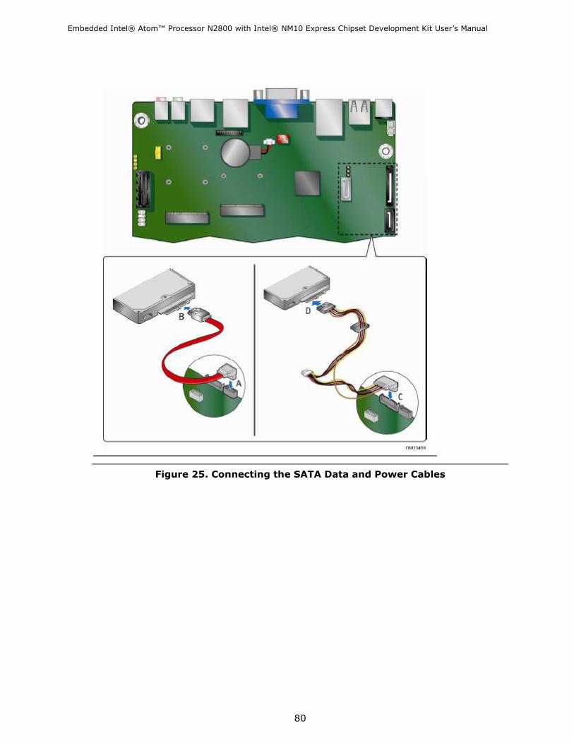
Embedded Intel® Atom™ Processor N2800 with Intel® NM10 Express Chipset Development Kit User‘s Manual
80
Figure 25. Connecting the SATA Data and Power Cables

Embedded Intel® Atom™ Processor N2800 with Intel® NM10 Express Chipset Development Kit User‘s Manual
81
3.7 Reliability
The Mean Time Between Failures (MTBF) prediction is calculated using component and
subassembly random failure rates. The calculation is based on the Telcordia SR-332
Issue 2, Method I, Case 3, 55 ºC ambient. The MTBF prediction is used to estimate
repair rates and spare parts requirements. The MTBF for the board is 319,009 hours.
3.8 Environmental
Table 40 lists the environmental specifications for the N2800 Embedded Board that
contains the Intel® Atom™ Processor N2800 and Intel® NM10 Express Chipset.
Table 40. Embedded Board Environmental Specifications
Parameter Specification
Temperature
Non-Operating -20 C to +70 C
Operating (ambient,
outside chassis)
0 C to +35 C
Operating
(inside chassis)
0 C to +55 C
Shock
Unpackaged 50 g trapezoidal waveform
Velocity change of 170 inches/s²
Packaged Half sine 2 millisecond
Product Weight (pounds) Free Fall (inches) Velocity Change (inches/s²)
<20 36 167
21-40 30 152
41-80 24 136
81-100 18 118
Vibration
Unpackaged 5 Hz to 20 Hz: 0.01 g² Hz sloping up to 0.02 g² Hz
20 Hz to 500 Hz: 0.02 g² Hz (flat)
Packaged 5 Hz to 40 Hz: 0.015 g² Hz (flat)
40 Hz to 500 Hz: 0.015 g² Hz sloping down to 0.00015 g² Hz
NOTE
Maximum operating temperatures based on fanless chassis configuration
(tests performed with Morex* T-1620 thin-mITX chassis).

Embedded Intel® Atom™ Processor N2800 with Intel® NM10 Express Chipset Development Kit User‘s Manual
82
4 Overview of BIOS Features
4.1 Introduction
This chapter describes the BIOS features of the Development Kit. Several subsections
also tell you how to update the BIOS by either using the Intel Express BIOS Update
utility or the Intel® Flash Memory Update Utility, and how to recover the BIOS if an
update fails.
The board uses an Intel BIOS that is stored in the Serial Peripheral Interface Flash
Memory (SPI Flash) and can be updated using a disk-based program. The SPI Flash
contains the BIOS Setup program, POST, the PCI auto-configuration utility, LAN
EEPROM information, and Plug and Play support.
The BIOS displays a message during POST identifying the type of BIOS and a revision
code.
When the BIOS Setup configuration jumper is set to configure mode and the computer
is powered-up, the BIOS compares the CPU version and the microcode version in the
BIOS and reports if the two match.
The BIOS Setup program can be used to view and change the BIOS settings for the
computer. The BIOS Setup program is accessed by pressing the <F2> key after the
Power-On Self-Test (POST) memory test begins and before the operating system boot
begins. The menu bar is shown below.
Maintenance Main Configuration Security Power Boot Exit
NOTE
The maintenance menu is displayed only when the board is in configure mode.
Section 3.4 shows how to put the board in configure mode.

Embedded Intel® Atom™ Processor N2800 with Intel® NM10 Express Chipset Development Kit User‘s Manual
83
Table 41 lists the BIOS Setup program menu features.
Table 41. BIOS Setup Program Menu Bar
Maintenance Main Configuration Security Power Boot Exit
Clears
passwords and
displays
processor
information
Displays
processor
and memory
configuration
Configures
advanced features
available through
the chipset
Sets
passwords
and
security
features
Configures power
management
features and
power supply
controls
Selects
boot
options
Saves or
discards changes
to Setup
program options
Table 42 lists the function keys available for menu screens.
Table 42. BIOS Setup Program Function Keys
BIOS Setup Program
Function Key
Description
<> or <> Selects a different menu screen (Moves the cursor left or right)
<> or <> Selects an item (Moves the cursor up or down)
<Tab> Selects a field (Not implemented)
<Enter> Executes command or selects the submenu
<F9> Load the default configuration values for the current menu
<F10> Save the current values and exits the BIOS Setup program
<Esc> Exits the menu
4.2 BIOS Flash Memory Organization
The Serial Peripheral Interface Flash Memory (SPI Flash) includes a 32 Mbit (4096 KB)
flash memory device.

Embedded Intel® Atom™ Processor N2800 with Intel® NM10 Express Chipset Development Kit User‘s Manual
84
4.3 System Management BIOS (SMBIOS)
SMBIOS is a Desktop Management Interface (DMI) compliant method for managing
computers in a managed network.
The main component of SMBIOS is the Management Information Format (MIF)
database, which contains information about the computing system and its
components. Using SMBIOS, a system administrator can obtain the system types,
capabilities, operational status, and installation dates for system components. The MIF
database defines the data and provides the method for accessing this information. The
BIOS enables applications such as third-party management software to use SMBIOS.
The BIOS stores and reports the following SMBIOS information:
BIOS data, such as the BIOS revision level
Fixed-system data, such as peripherals, serial numbers, and asset tags
Resource data, such as memory size, cache size, and processor speed
Dynamic data, such as event detection and error logging
Non-Plug and Play operating systems require an additional interface for obtaining the
SMBIOS information. The BIOS supports an SMBIOS table interface for such operating
systems. Using this support, an SMBIOS service-level application running on a
non-Plug and Play operating system can obtain the SMBIOS information. Additional
board information can be found in the BIOS under the Additional Information header
under the Main BIOS page.
4.4 Legacy USB Support
Legacy USB support enables USB devices to be used even when the operating system‘s
USB drivers are not yet available. Legacy USB support is used to access the BIOS
Setup program, and to install an operating system that supports USB. By default,
Legacy USB support is set to Enabled.
Legacy USB support operates as follows:
1. When you apply power to the computer, legacy support is disabled.
2. POST begins.
3. Legacy USB support is enabled by the BIOS allowing you to use a USB keyboard to
enter and configure the BIOS Setup program and the maintenance menu.
4. POST completes.
5. The operating system loads. While the operating system is loading, USB keyboards
and mice are recognized and may be used to configure the operating system.
(Keyboards and mice are not recognized during this period if Legacy USB support
was set to Disabled in the BIOS Setup program.)
6. After the operating system loads the USB drivers, all legacy and non-legacy USB
devices are recognized by the operating system, and Legacy USB support from the
BIOS is no longer used.
7. Additional USB legacy feature options can be accessed by using the Intel®
Integrator Toolkit.

Embedded Intel® Atom™ Processor N2800 with Intel® NM10 Express Chipset Development Kit User‘s Manual
85
To install an operating system that supports USB, verify that Legacy USB support in
the BIOS Setup program is set to Enabled and follow the operating system‘s
installation instructions.
4.5 BIOS Updates
The BIOS can be updated using either of the following utilities, which are available on
the Intel World Wide Web site:
Intel® Express BIOS Update utility, which enables automated updating while in the
Windows environment. Using this utility, the BIOS can be updated from a file on a
hard disk, a USB drive (a flash drive or a USB hard drive), a CD-ROM, or from the
file location on the Web.
Intel® F7 switch during POST allows a user to select where the BIOS .bio file is located and perform the update from that location/device. Similar to performing a BIOS Recovery without removing the BIOS configuration jumper.
Intel® Flash Memory Update Utility, which requires booting from DOS. Using this
utility, the BIOS can be updated from a file on a hard disk, a USB drive (a flash
drive or a USB hard drive), or a CD-ROM.
Both utilities verify that the updated BIOS matches the target system to prevent
accidentally installing an incompatible BIOS.
4.5.1 Updating the BIOS with the Intel® Express BIOS Update Utility
With the Intel Express BIOS Update utility you can update the system BIOS while in
the Windows environment. The BIOS file is included in an automated update utility
that combines the functionality of the Intel Flash Memory Update Utility and the ease
of use of Windows-based installation wizards.
To update the BIOS with the Intel Express BIOS Update utility:
1. Go to the Intel World Wide Web site Download Center at http://downloadcenter.intel.com/
2. Navigate to the DN2800MT page. Click on the ―BIOS Update‖ link and then select the Express BIOS Update file.
3. Download the file to your hard drive. (You can also save this file to a removable USB device. This is useful if you are updating the BIOS for multiple identical systems.)
4. Close all other applications. This step is required. Your system will be rebooted at the last Express BIOS Update window.
5. Double-click the executable file from the location on your hard drive where it was saved. This runs the update program. Follow the instructions provided in the dialog boxes to complete the BIOS update

Embedded Intel® Atom™ Processor N2800 with Intel® NM10 Express Chipset Development Kit User‘s Manual
86
4.5.2 Updating the BIOS Using the F7 Function Key
To use this BIOS update method:
1. Download and save the Recovery BIOS (.BIO) file to a temporary directory. 2. Copy the .BIO file to a USB thumb drive. 3. Plug the thumb drive into a USB port of the target computer. 4. Shut down the target computer. 5. Enable the F7 prompt display:
a. Power the computer on. b. Enter the BIOS Setup by pressing the F2 key during boot. c. Go to the Advanced > Boot Configuration menu. d. Enable Display F7 to Update BIOS e. Press the F10 key to save and exit.
6. During boot, when the F7 prompt is displayed, press the F7 key to enter the BIOS Flash Update tool.
7. Select the USB thumb drive and press Enter. 8. Select the .BIO file and press Enter 9. Confirm you want to update the BIOS by pressing Enter. 10. Wait 2-5 minutes for the update to complete. 11. Remove the thumb drive. 12. Restart the computer.
4.5.3 Updating the BIOS with the Intel® Flash Memory Update Utility
You can use the information in this section to update the BIOS using the Intel® Flash Memory Update Utility. With the Intel Flash Memory Update Utility you can update the system BIOS from a bootable CD-ROM, bootable USB flash drive, or other bootable USB media. You can update to a new version of the BIOS by using the Intel Flash Memory BIOS update file. The Intel Flash Memory BIOS update file is a compressed file that contains the files you need to update the BIOS. The BIOS update file contains:
• New BIOS file (including the Intel® Management Engine (Intel® ME) Firmware
Image) • Intel® Integrator Toolkit Configuration File (optional)
• Intel Flash Memory Update Utility
You can obtain this file on http://downloadcenter.intel.com (the Intel Download Center homepage) by typing in ―DN2800MT‖ or ―N2800‖ in the Search Downloads area and then navigating to the Intel Embedded Board N2800 page. Once on the N2800 page, click on the ―BIOS‖ selection in the Download type section and then select the flash BIOS Update file.
NOTE
Review the instructions distributed with the upgrade utility before attempting a BIOS
update.

Embedded Intel® Atom™ Processor N2800 with Intel® NM10 Express Chipset Development Kit User‘s Manual
87
For information about Refer to
BIOS update utilities http://support.intel.com/support/motherboards/desktop/sb
/CS-022312.htm.
CAUTION
Do not interrupt the process or the system may not function properly.
1. Uncompress the BIOS update file and copy the .BIO file, IFLASH2.EXE, and .ITK file (optional) to a bootable USB flash drive or other bootable USB media. 2. Configure the BIOS or use the F10 key option during POST to boot to the USB device. 3. Manually run the IFLASH2.EXE file from the USB device and manually update the BIOS.
DO NOT POWER DOWN YOUR COMPUTER before the update is complete. The update
may take up to 5 minutes.
4.5.4 Language Support
The BIOS Setup program and help messages are supported in US English. Check the
Intel web site for support.
4.5.5 Custom Splash Screen
During POST, an Intel® splash screen is displayed by default. This splash screen can
be augmented with a custom splash screen. The Intel Integrator‘s Toolkit that is
available from Intel can be used to create a custom splash screen.
NOTE
If you add a custom splash screen, it will share space with the Intel branded logo.
For information about Refer to
Intel Integrator Toolkit http://developer.intel.com/design/motherbd/software/itk/
Additional Intel® software tools http://developer.intel.com/design/motherbd/software.htm
4.6 BIOS Recovery
It is unlikely that anything will interrupt a BIOS update; however, if an interruption
occurs, the BIOS could be damaged. Table 43 lists the drives and media types that
can and cannot be used for BIOS recovery. The BIOS recovery media does not need to
be made bootable.
For more information about updating the Intel Desktop Board BIOS or recovering from a BIOS update failure, go to http://support.intel.com/support/motherboards/desktop/sb/CS-022312.htm.

Embedded Intel® Atom™ Processor N2800 with Intel® NM10 Express Chipset Development Kit User‘s Manual
88
Table 43. Acceptable Drives/Media Types for BIOS Recovery
Media Type (Note) Can be used for BIOS recovery?
Hard disk drive (connected to SATA or USB) Yes
CD/DVD drive (connected to SATA or USB) Yes
USB flash drive Yes
USB diskette drive (with a 1.4 MB diskette) No (BIOS update file is bigger than 1.4 MB size limit)
NOTE
Supported file systems for BIOS recovery:
NTFS (sparse, compressed, or encrypted files are not supported)
FAT32
FAT16
FAT12
ISO 9660
For information about Refer to
BIOS recovery http://www.intel.com/support/motherboards/desktop/sb/cs-023360.htm
4.7 Boot Options
In the BIOS Setup program, the user can choose to boot from a hard drive, optical
drive, removable drive, or the network. The default setting is for the optical drive to
be the first boot device, the hard drive second, removable drive third, and the network
fourth.
4.7.1 Optical Drive Boot
Booting from the optical drive is supported in compliance to the El Torito bootable
CD-ROM format specification. Under the Boot menu in the BIOS Setup program, the
optical drive is listed as a boot device. Boot devices are defined in priority order.
Accordingly, if there is not a bootable CD in the optical drive, the system will attempt
to boot from the next defined drive.
4.7.2 Network Boot
The network can be selected as a boot device. This selection allows booting from the
onboard LAN or a network add-in card with a remote boot ROM installed.
Pressing the <F12> key during POST automatically forces booting from the LAN. To
use this key during POST, the User Access Level in the BIOS Setup program's Security
menu must be set to Full.

Embedded Intel® Atom™ Processor N2800 with Intel® NM10 Express Chipset Development Kit User‘s Manual
89
4.7.3 Booting Without Attached Devices
For use in embedded applications, the BIOS has been designed so that after passing
the POST, the operating system loader is invoked even if the following devices are not
present:
Video adapter
Keyboard
Mouse
4.7.4 Changing the Default Boot Device During POST
Pressing the <F10> key during POST causes a boot device menu to be displayed. This
menu displays the list of available boot devices. Table 44 lists the boot device menu
options.
Table 44. Boot Device Menu Options
Boot Device Menu Function Keys Description
<> or <> Selects a default boot device
<Enter> Exits the menu, and boots from the selected device
<Esc> Exits the menu and boots according to the boot priority
defined through BIOS setup
4.8 Adjusting Boot Speed
These factors affect system boot speed:
Selecting and configuring peripherals properly
Optimized BIOS boot parameters
Enabling the new Fast Boot feature
4.8.1 Peripheral Selection and Configuration
The following techniques help improve system boot speed:
Choose a hard drive with parameters such as ―power-up to data ready‖ in less than
eight seconds that minimizes hard drive startup delays.
Select a CD-ROM drive with a fast initialization rate. This rate can influence POST
execution time.
Eliminate unnecessary add-in adapter features, such as logo displays, screen
repaints, or mode changes in POST. These features may add time to the boot
process.
Try different monitors. Some monitors initialize and communicate with the BIOS
more quickly, which enables the system to boot more quickly.
4.9 Hard Disk Drive Password Security Feature
The Hard Disk Drive Password Security feature blocks read and write accesses to the
hard disk drive until the correct password is given. Hard Disk Drive Passwords are set

Embedded Intel® Atom™ Processor N2800 with Intel® NM10 Express Chipset Development Kit User‘s Manual
90
in BIOS SETUP and are prompted for during BIOS POST. For convenient support of S3
resume, the system BIOS will automatically unlock drives on resume from S3.
The User hard disk drive password, when installed, will be required upon each power-
cycle until the Master Key or User hard disk drive password is submitted.
The Master Key hard disk drive password, when installed, will not lock the drive. The
Master Key hard disk drive password exists as an unlock override in the event that the
User hard disk drive password is forgotten. Only the installation of the User hard disk
drive password will cause a hard disk to be locked upon a system power-cycle.
Table 45 shows the effects of setting the Hard Disk Drive Passwords.
Table 45. Master Key and User Hard Drive Password Functions
Password Set Password During Boot
Neither None
Master only None
User only User only
Master and User Set Master or User
During every POST, if a User hard disk drive password is set, POST execution will
pause with the following prompt to force the user to enter the Master Key or User hard
disk drive password:
Enter Hard Disk Drive Password:
Upon successful entry of the Master Key or User hard disk drive password, the system
will continue with normal POST.
If the hard disk drive password is not correctly entered, the system will go back to the
above prompt. The user will have three attempts to correctly enter the hard disk drive
password. After the third unsuccessful hard disk drive password attempt, the system
will halt with the message:
Hard Disk Drive Password Entry Error
A manual power cycle will be required to resume system operation.
NOTE
As implemented on the N2800 Embedded Board, Hard Disk Drive Password Security is
only supported on SATA port 0. The passwords are stored on the hard disk drive so if
the drive is relocated to another SATA port or computer that does not support Hard
Disk Drive Password Security feature, the drive will not be accessible.
4.10 BIOS Security Features
The BIOS includes security features that restrict access to the BIOS Setup program
and who can boot the computer. A supervisor password and a user password can be

Embedded Intel® Atom™ Processor N2800 with Intel® NM10 Express Chipset Development Kit User‘s Manual
91
set for the BIOS Setup program and for booting the computer, with the following
restrictions:
The supervisor password gives unrestricted access to view and change all the Setup
options in the BIOS Setup program. This is the supervisor mode.
The user password gives restricted access to view and change Setup options in the
BIOS Setup program. This is the user mode.
If only the supervisor password is set, pressing the <Enter> key at the password
prompt of the BIOS Setup program allows the user restricted access to Setup.
If both the supervisor and user passwords are set, users can enter either the
supervisor password or the user password to access Setup. Users have access to
Setup respective to which password is entered.
Setting the user password restricts who can boot the computer. The password
prompt will be displayed before the computer is booted. If only the supervisor
password is set, the computer boots without asking for a password. If both
passwords are set, the user can enter either password to boot the computer.
For enhanced security, use different passwords for the supervisor and user
passwords.
Valid password characters are A-Z, a-z, and 0-9. Passwords may be up to
16 characters in length.
Table 46 shows the effects of setting the supervisor password and user password. This
table is for reference only and is not displayed on the screen.
Table 46. Supervisor and User Password Functions
Password
Set
Supervisor
Mode
User Mode
Setup Options
Password
to Enter
Setup
Password
During
Boot
Neither Can change all
options (Note)
Can change all
options (Note)
None None None
Supervisor
only
Can change all
options
Can change a
limited
number of
options
Supervisor Password Supervisor None
User only N/A Can change all
options
Enter Password
Clear User Password
User User
Supervisor
and user set
Can change all
options
Can change a
limited
number of
options
Supervisor Password
Enter Password
Supervisor or
user
Supervisor or
user
Note: If no password is set, any user can change all Setup options.

Embedded Intel® Atom™ Processor N2800 with Intel® NM10 Express Chipset Development Kit User‘s Manual
92
5 Error Messages and Beep Codes
This chapter describes error messages generated by the Development Kit‘s BIOS. The BIOS indicates these error messages with LED blink codes, speaker beep codes, and by text displayed on the PC monitor.
5.1 Speaker
Audible error code (beep code) information during POST is routed to the audio codec
and can be heard through attached speakers.
5.2 BIOS Beep Codes
Whenever a recoverable error occurs during POST, the BIOS causes the board‘s
speaker to beep an error message describing the problem (see Table 47).
Table 47. BIOS Beep Codes
Type Pattern Frequency
BIOS update in progress None
Video error (Note)
On-off (1.0 second each) two times, then
2.5-second pause (off), entire pattern repeats
(beeps and pause) once and the BIOS will
continue to boot.
932 Hz
When no VGA option ROM is
found.
Memory error On-off (1.0 second each) three times, then
2.5-second pause (off), entire pattern repeats
(beeps and pause) until the system is powered
off.
932 Hz
Thermal trip warning Alternate high and low beeps (1.0 second each)
for eight beeps, followed by system shut down.
High beep 2000 Hz
Low beep 1500 Hz
Note: Disabled per default BIOS setup option.

Embedded Intel® Atom™ Processor N2800 with Intel® NM10 Express Chipset Development Kit User‘s Manual
93
5.3 Front-panel Power LED Blink Codes
Whenever a recoverable error occurs during POST, the BIOS causes the board‘s front
panel power LED to blink an error message describing the problem (see Table 48).
Table 48. Front-panel Power LED Blink Codes
Type Pattern Note
BIOS update in progress Off when the update begins, then on for
0.5 seconds, then off for 0.5 seconds. The
pattern repeats until the BIOS update is
complete.
Video error (Note)
On-off (1.0 second each) two times, then
2.5-second pause (off), entire pattern repeats
(blink and pause) until the system is powered
off.
When no VGA option ROM is
found.
Memory error On-off (1.0 second each) three times, then
2.5-second pause (off), entire pattern repeats
(blinks and pause) until the system is powered
off.
Thermal trip warning Each beep will be accompanied by the following
blink pattern: .25 seconds on, .25 seconds off,
.25 seconds on, .25 seconds off. This will result
in a total of 16 blinks.
Note: Disabled per default BIOS setup option.
5.4 BIOS Error Messages
Table 49 lists the error messages and provides a brief description of each.
Table 49. BIOS Error Messages
Error Message Explanation
CMOS Battery Low The battery may be losing power. Replace the battery soon.
CMOS Checksum Bad The CMOS checksum is incorrect. CMOS memory may have
been corrupted. Run Setup to reset values.
Memory Size Decreased Memory size has decreased since the last boot. If no memory
was removed, then memory may be bad.
No Boot Device Available System did not find a device to boot.

Embedded Intel® Atom™ Processor N2800 with Intel® NM10 Express Chipset Development Kit User‘s Manual
94
5.5 Port 80h POST Codes
During the POST, the BIOS generates diagnostic progress codes (POST codes) to I/O
port 80h. If the POST fails, execution stops and the last POST code generated is left at
port 80h. This code is useful for determining the point where an error occurred.
Displaying the POST codes requires a POST card that can interface with the Debug
header. The POST card can decode the port and display the contents on a medium
such as a seven-segment display. Refer to the location of the Debug header in
Figure 1.
The following tables provide information about the POST codes generated by the BIOS:
Table 50 lists the Port 80h POST code ranges
Table 51 lists the Port 80h POST codes themselves
Table 52 lists the Port 80h POST sequence
NOTE
In the tables listed above, all POST codes and range values are listed in hexadecimal.
Table 50. Port 80h POST Code Ranges
Range Subsystem
0x00 – 0x05 Entering SX states S0 to S5.
0x10, 0x20, 0x30 Resuming from SX states (0x10 –0x20 – S2, 0x30 – S3, etc.)
0x11 – 0x1F PEI phase pre MRC execution
0x21 – 0x29 MRC memory detection
0x2A – 0x2F PEI phase post MRC execution
0x31 – 0x35 Recovery
0x36 – 0x3F Platform DXE driver
0x41 – 0x4F CPU Initialization (PEI, DXE, SMM)
0x50 – 0x5F I/O Buses: PCI, USB, ATA etc. 0x5F is an unrecoverable error. Start with PCI.
0x60 – 0x6F BDS
0x70 – 0x7F Output devices: All output consoles.
0x80 – 0x8F For future use
0x90 – 0x9F Input devices: Keyboard/Mouse.
0xA0 – 0xAF For future use
0xB0 – 0xBF Boot Devices: Includes fixed media and removable media. Not that critical since
consoles should be up at this point.
0xC0 – 0xCF For future use
0xD0 – 0xDF For future use

Embedded Intel® Atom™ Processor N2800 with Intel® NM10 Express Chipset Development Kit User‘s Manual
95
Table 51. Port 80h POST Codes
Port 80 Code Progress Code Enumeration
ACPI S States
0x00,0x01,0x02,0x03,0x04,0x05 Entering S0, S2, S3, S4, or S5 state
0x10,0x20,0x30 Resuming from S2, S3, S4, or S5 state
PEI Platform driver
0x11 Set boot mode, GPIO init
0x12 Early chipset register programming
0x13 Basic chipset init
0x14 LAN init
0x15 Exit early platform init driver
PEI SMBUS
0x16 SMBUS driver init
0x17 Entry to SMBUS execute read/write
0x18 Exit SMBUS execute read/write
Memory
0x21 MRC entry point
0x24 Detecting presence of memory DIMMs
0x25 Override Detected DIMM settings
0x27 Configuring memory
0x28 Testing memory
PEIMs/Recovery
0x31 Crisis Recovery has initiated
0x33 Loading recovery capsule
0x34 Start recovery capsule / valid capsule is found
CPU PEI Phase
0x41 Begin CPU PEI Init
0x42 XMM instruction enabling
0x43 End CPU PEI Init
CPU PEI SMM Phase
0x44 Begin CPU SMM Init smm relocate bases
0x45 Smm relocate bases for APs
0x46 End CPU SMM Init
CPU DXE Phase
0x47 CPU DXE Phase begin
0x48 Refresh memory space attributes according to MTRRs
0x49 Load the microcode if needed
0x4A Initialize strings to HII database
0x4B Initialize MP support
0x4C CPU DXE Phase End
continued

Embedded Intel® Atom™ Processor N2800 with Intel® NM10 Express Chipset Development Kit User‘s Manual
96
Table 51. Port 80h POST Codes (continued)
Port 80 Code Progress Code Enumeration
CPU DXE SMM Phase
0x4D CPU DXE SMM Phase begin
0x4E Relocate SM bases for all APs
0x4F CPU DXE SMM Phase end
I/O BUSES
0x50 Enumerating PCI buses
0x51 Allocating resources to PCI bus
0x52 Hot Plug PCI controller initialization
USB
0x58 Resetting USB bus
0x59 Reserved for USB
ATA/ATAPI/SATA
0x5A Resetting PATA/SATA bus and all devices
0x5B Reserved for ATA
BDS
0x60 BDS driver entry point initialize
0x61 BDS service routine entry point (can be called multiple times)
0x62 BDS Step2
0x63 BDS Step3
0x64 BDS Step4
0x65 BDS Step5
0x66 BDS Step6
0x67 BDS Step7
0x68 BDS Step8
0x69 BDS Step9
0x6A BDS Step10
0x6B BDS Step11
0x6C BDS Step12
0x6D BDS Step13
0x6E BDS Step14
0x6F BDS return to DXE core (should not get here)
Keyboard (PS/2 or USB)
0x90 Resetting keyboard
0x91 Disabling the keyboard
0x92 Detecting the presence of the keyboard
0x93 Enabling the keyboard
0x94 Clearing keyboard input buffer
0x95 Instructing keyboard controller to run Self Test (PS/2 only)
continued

Embedded Intel® Atom™ Processor N2800 with Intel® NM10 Express Chipset Development Kit User‘s Manual
97
Table 51. Port 80h POST Codes (continued)
Port 80 Code Progress Code Enumeration
Mouse (PS/2 or USB)
0x98 Resetting mouse
0x99 Detecting mouse
0x9A Detecting presence of mouse
0x9B Enabling mouse
Fixed Media
0xB0 Resetting fixed media
0xB1 Disabling fixed media
0xB2 Detecting presence of a fixed media (IDE hard drive detection etc.)
0xB3 Enabling/configuring a fixed media
Removable Media
0xB8 Resetting removable media
0xB9 Disabling removable media
0xBA Detecting presence of a removable media (IDE, CDROM detection
etc.)
0xBC Enabling/configuring a removable media
DXE Core
0xE4 Entered DXE phase
BDS
0xE7 Waiting for user input
0xE8 Checking password
0xE9 Entering BIOS setup
0xEB Calling Legacy Option ROMs
Runtime Phase/EFI OS Boot
0xF8 EFI boot service ExitBootServices ( ) has been called
0xF9 EFI runtime service SetVirtualAddressMap ( ) has been called

Embedded Intel® Atom™ Processor N2800 with Intel® NM10 Express Chipset Development Kit User‘s Manual
98
Table 52. Typical Port 80h POST Sequence
POST Code Description
24 Detecting presence of memory DIMMs
27 Configuring memory
28 Testing memory
33 Loading recovery capsule
E4 Entered DXE phase
50 Enumerating PCI busses
51 Allocating resources to PCI bus
92 Detecting the presence of the keyboard
90 Resetting keyboard
94 Clearing keyboard input buffer
95 Keyboard Self Test
EB Calling Video BIOS
58 Resetting USB bus
5A Resetting PATA/SATA bus and all devices
92 Detecting the presence of the keyboard
90 Resetting keyboard
94 Clearing keyboard input buffer
5A Resetting PATA/SATA bus and all devices
28 Testing memory
90 Resetting keyboard
94 Clearing keyboard input buffer
E7 Waiting for user input
00 Ready to boot

Embedded Intel® Atom™ Processor N2800 with Intel® NM10 Express Chipset Development Kit User‘s Manual
99
6 Assembly/Disassembly Guide
6.1 Introduction
Please take a moment and read this manual before you start assembling or
disassembling this enclosure. Often times, rushing into unit installation can result in
damage to your enclosure, motherboard, and power supply.
6.2 Required tools
Phillips screwdriver
6.3 Board Installation Steps
1. To remove the top lid, remove the screw (encircled in red) from the back, in the right corner, see Figure 26. Push back the top lid ½ inches and after this, gently pull it up.
Figure 26. Removing the top lid
1 - WiFi antenna hole, 2 - DC Power jack hole
2. Install I/O motherboard shield on the back of the enclosure.
3. Install the motherboard on the base plate using four screws as shown in Figure 27.

Embedded Intel® Atom™ Processor N2800 with Intel® NM10 Express Chipset Development Kit User‘s Manual
100
Figure 27. Install Motherboard
4. Connect the ON/OFF and Power LED cables (J3 in Figure 28) to the motherboard using the cable harness provided with the enclosure, see Figure 28. Also, you can connect the USB header (J2 in Figure 28), if needed. Connect the ON/OFF and Power LED cables (J3 in Figure 28) to the motherboard using the cable harness provided with the enclosure. Also, you can connect the USB header, if needed.
Figure 28. J2 (USB Header) and J3 (2x3) pin header, view from the back of Enclosure
6.4 Installing USB devices under the front plate The front plate is designed to conceal USB flash drives, Bluetooth, USB WIFI modules or
other USB devices. To add a USB device under the front plate, remove it by carefully
pressing outwards and gently pushing, one by one, the plastic lids from the sides (see
Figure 29).

Embedded Intel® Atom™ Processor N2800 with Intel® NM10 Express Chipset Development Kit User‘s Manual
101
Figure 29. Removing the front plate by pressing the left and right plastic lids
Near the front USB connector there are 2 jumpers (Figure 30) which are used to customize
how the board will start.
JP1: Disable On/Off power button (removing this jumper disables the power button).
JP2: Enable auto start (set power button on ―ON‖ state always).
Figure 30. JP1, JP2 pin header and 2 x USB slots
Front view of the enclosure, with the front plate removed.
After installing the desired USB devices, snap back the front plate.

Embedded Intel® Atom™ Processor N2800 with Intel® NM10 Express Chipset Development Kit User‘s Manual
102
6.5 Installing SSD and Fans Install the SSD using the provided screws. The SSD (and optional coolers) will be fastened
onto the SSD Mounting Bracket see Figure 31. On the bracket you can install one 2.5‖ hard
drive or two fans (40x40x10mm) pictured below.
Figure 31. Mounting Bracket for SDD, HDD, or Fan

Embedded Intel® Atom™ Processor N2800 with Intel® NM10 Express Chipset Development Kit User‘s Manual
103
7 Operating System Reference
7.1 Installing Windows* 7
This section provides step-by-step instructions for installing Windows* 7 on platforms
based on the Intel® Atom™ Processor N2000 or D2000 Series and Intel® NM10
Express Chipset.
The instructions in this section have been validated with the Intel® Atom™ Processor
D2700 with Intel® NM10 Express Chipset and Intel® Atom™ Processor N2800 with
Intel® NM10 Express Chipset Development Kits. However, the information in this
section is applicable to any Intel platform based on the Intel® Atom™ Processor
N2000 or D2000 Series and Intel® NM10 Express Chipset.
For customers evaluating or using the Development Kit(s) as a basis for their
embedded design and Windows 7 as their operating system, this is the primary
guidance Intel provides for installing the drivers and operating system to deliver
optimized performance.
Windows 7 is the 2009 release of Microsoft Windows which is a series of operating
systems produced by Microsoft for use on all different types of personal computers,
including home and business desktops, laptops, netbooks, tablet PCs, and media
center PCs.
Windows 7 is an officially supported OS for this platform. Starter, Home Basic and
Home Premium are the supported versions of this OS for this platform.
Note: Six additional plan of record operating systems exist for this platform as well:
Windows XP, Windows XP Embedded (XPe), Yocto Project, MeeGo 1.2, VxWorks,
Windows Embedded Compact 7, and Windows Embedded Standard 7 (WES7).
Hardware and software required for installation of Windows 7 and the drivers made by
Intel on this platform include:
• A system designed to Intel‘s platform design guide recommendations
• 40 GB or larger blank hard disk drive (HDD) or SSD
• USB DVD-ROM drive (or USB flash drive depending on how Microsoft Windows
7 is downloaded and installed)
7.1.1 Downloading and installing Windows 7 onto the Target SSD/HDD
Windows 7 is a closed source platform that includes the kernel, core OS, UI libraries
and tools, reference user experiences for multiple devices and applications, a standard
set of APIs across all target device types, and the flexibility to support add-ons and
applications. Since Windows 7 is the exclusive property of Microsoft, Intel is legally not
allowed to distribute a BSP or full OS image with Intel drivers already pre-installed in

Embedded Intel® Atom™ Processor N2800 with Intel® NM10 Express Chipset Development Kit User‘s Manual
104
it. The purpose of this section is thus to provide the instructions necessary for
downloading and creating the Microsoft Windows 7 OS and then installing the drivers
created by Intel for this platform under Windows 7.
Before proceeding with the rest of this section which covers how to install Intel-created
graphics, chipset and processor drivers into the target Windows 7 based platform,
customers must first obtain a blank SATA based HDD or SSD (recommended size = 40
GB or more) and choose one of the acceptable methods in Table 53 to install Windows
7 from scratch.
Table 53. Windows 7 Installation Options
If you want to do this Go here for more information
Format the HDD/SSD and
install Windows 7.
http://windows.microsoft.com/en-us/windows7/Installing-and-reinstalling-
Windows-7
See "Using the Custom installation option and formatting the hard disk" in
this topic
Install Windows 7 on a
HDD/SSD that did not
previously have an operating
system.
http://windows.microsoft.com/en-us/windows7/Installing-and-reinstalling-
Windows-7
See "Using the Custom installation option if no operating system is
installed" in this topic.
Install Windows 7 on a
HDD/SSD based platform
without using a DVD drive.
For information about downloading Windows 7, and then creating a USB
flash drive to install Windows 7, go to: http://windows.microsoft.com/en-
us/windows7/installing-windows-7-on-a-netbook
NOTE: Instructions are courtesy of Microsoft.
Once the SSD/HDD contains a fresh version of Windows 7, it is recommended that the
latest service pack be downloaded and installed.
Note: This may not be necessary if the latest service pack is integrated into the
original OS installation.
A service pack (SP) is a Windows update, often integrating previously released
updates, that helps make Windows more reliable. Service packs, which are provided
free of charge by Microsoft, can include security and performance improvements and
support for new types of hardware. Installing the latest service pack helps keep
Windows 7 up to date.
The easiest way to get any necessary service packs is to use the target platform‘s
Windows 7 and turn on Windows Update for Windows 7. Step by step instructions on
how to do this are posted here from Microsoft: http://windows.microsoft.com/en-
US/windows7/learn-how-to-install-windows-7-service-pack-1-sp1
As of January 2012, the most recent service pack available for manual download is R2
SP1 (Service Pack 1). Download R2 SP1 from the Download Center here:
http://www.microsoft.com/download/en/details.aspx?displaylang=en&id=5842#overvi
ew
Turning on Automatic Updating is optional. If you are creating a golden image for
prototyping or production purposes, having explicit control over operating system
updates is recommended.

Embedded Intel® Atom™ Processor N2800 with Intel® NM10 Express Chipset Development Kit User‘s Manual
105
7.1.2 Downloading and installing processor, graphics,
chipset and other optional drivers
Though the standard OS may contain several drivers compatible with the platform it is
recommended that you install the latest platform drivers found here:
http://downloadcenter.intel.com/SearchResult.aspx?lang=eng&ProductFamily=Deskto
p+Boards&ProductLine=Intel%c2%ae+NM10+Chipset+Family+Boards&ProductProduct
=Intel%c2%ae+Desktop+Board+DN2800MT&DownloadType=Drivers
These drivers, in pre-release and release forms, are also available in the same package
format from https://platformsw.intel.com. Please see your Intel field representative for
access.
Driver files are generally available as an executable file. If you have downloaded the
package file to your platform, and it is in ZIP format, extract the contents of the file
using a file decompression program such as WinZip* or 7-Zip*.
7.2 Installing Windows* Embedded Standard 7
This section provides step-by-step instructions for installing Windows* Embedded
Standard 7 on platforms based on the Intel® Atom™ Processor N2000 or D2000 Series
and Intel® NM10 Express Chipset.
The instructions in this section have been validated with the Intel® Atom™ Processor
D2700 with Intel® NM10 Express Chipset and Intel® Atom™ Processor N2800 with
Intel® NM10 Express Chipset Development Kits. However, the information in this
section is applicable to any Intel platform based on the Intel® Atom™ Processor
N2000 or D2000 Series and Intel® NM10 Express Chipset.
For customers evaluating or using the Development Kit(s) as a basis for their
embedded design, and Windows Embedded Standard 7 as their operating system, this
is the primary guidance Intel provides for installing the drivers and operating system
to deliver optimized performance.
Windows Embedded Standard 7, abbreviated WES7, is a Windows 7 compatible
operating system from Microsoft designed specifically for use in embedded systems.
With WES7 software developers and system engineers have the ability to customize
the operating system by selecting components they most need to run their advanced
commercial and consumer devices and existing Windows applications and drivers.
Developers can use Windows Embedded Standard 7 and the component selection
menu built into it to create a custom, segment specific and highly space conscious OS
build for a variety of connected, and service-oriented advanced commercial or
consumer devices. Examples include operating system customizations for set-top
boxes, full featured point of service appliances, gaming devices, industrial controls,
multimedia internet devices, kiosks, digital signage, monitoring devices, and thin
clients.
According to Microsoft, Windows Embedded Standard 7, is based on Windows 7 which
was previously codenamed Windows Embedded ‗Quebec‘. Windows Embedded

Embedded Intel® Atom™ Processor N2800 with Intel® NM10 Express Chipset Development Kit User‘s Manual
106
Standard 7 includes Windows Vista and Windows 7 features such as Aero, SuperFetch,
ReadyBoost, BitLocker Drive Encryption, Windows Firewall, Windows Defender, Address
space layout randomization, Windows Presentation Foundation, Silverlight 2, Windows
Media Center among several other packages. Windows Embedded Standard 7 is x86
compatible and applications that run under Windows 7 should perform equivalently
under WES7.
Hardware and software required for installation of Windows 7 and the drivers made by
Intel on this platform include:
• A system designed to Intel‘s platform design guide recommendations
• 40 GB or larger blank hard disk drive (HDD) or SSD
• USB DVD-ROM drive (or USB flash drive depending on how Microsoft Windows 7 is
downloaded and installed)
• Windows Embedded Standard 7 DVD Image
7.2.1 Downloading, burning, and installing the WES7 DVD image
A DVD image for Windows Embedded Standard 7 SP1 with registration instructions for
trial and full licenses can be found at:
http://www.microsoft.com/windowsembedded/en-us/downloads/download-windows-
embedded-standard-7.aspx
Download the image per the instructions provided by Microsoft on the page and burn
to a writeable DVD disc.
7.2.2 Install WES7
1. Ensure that the hard disk or SSD to be used is not bootable to any operating
system, and that the USB DVD-ROM drive is connected to platform.
2. Boot the system with the WES7 DVD you have created. Choose Build an Image as
shown in Figure 32.

Embedded Intel® Atom™ Processor N2800 with Intel® NM10 Express Chipset Development Kit User‘s Manual
107
Figure 32: Build an image
3. Read and accept the license as shown in Figure 33. Click Next
Figure 33: Accept the license terms
4. WES7 allows you to choose from several pre-configured templates when creating
your image. Each selection has a different set of driver support and potentially
different look and feel for the user interface. The default is Application Compatibility,

Embedded Intel® Atom™ Processor N2800 with Intel® NM10 Express Chipset Development Kit User‘s Manual
108
which installs many of the basic Windows applications (Media Player, Internet explorer,
etc.) and drivers necessary for broad application support with the default windows
desktop look and feel. Intel recommends that you click View Template on each as
shown Figure 34.
Figure 34: View template
5. The template view will show you a list of the applications, drivers, and feature
packages selected by each template. An example of the Application Compatibility
template view is in Figure 35. When you are satisfied with your choice of template,
click Close. Intel recommends that you thoroughly review each of the templates before
clicking Next.
Figure 35: Template details

Embedded Intel® Atom™ Processor N2800 with Intel® NM10 Express Chipset Development Kit User‘s Manual
109
You may also choose Do not use a template to create your own customized image with
only the drivers and features that you need for your specific product implementation.
In that case, select the desired features that you need, and click Next.
6. Select your preferred language and keyboard region as shown in Figure 36.
Figure 36: Choose a language and other preferences
7. Select a disk install location as shown in Figure 37. You may want to delete any
existing partitions that appear in the list. If not, you can use an unallocated section or
create one using the options. Note that you will likely need at least 8GB of free space
for an install depending on which image options and features you chose in step 5.
When you are finished, click Next.
Figure 37: Where do you want to install Windows?

Embedded Intel® Atom™ Processor N2800 with Intel® NM10 Express Chipset Development Kit User‘s Manual
110
8. The installation will run for several minutes. During this time, the system may
restart a number of times.
Figure 38: Installing Windows
9. When the install process completes, you will be presented with a login screen,
where you can establish a user account and name for your system.
Figure 39: Set up Windows - Login
7.2.3 Downloading and installing processor, graphics, chipset and other optional drivers
Though the standard OS may contain several drivers compatible with the platform it is
recommended that you install the latest platform drivers found here:

Embedded Intel® Atom™ Processor N2800 with Intel® NM10 Express Chipset Development Kit User‘s Manual
111
http://downloadcenter.intel.com/SearchResult.aspx?lang=eng&ProductFamily=Deskto
p+Boards&ProductLine=Intel%c2%ae+NM10+Chipset+Family+Boards&ProductProduct
=Intel%c2%ae+Desktop+Board+DN2800MT&DownloadType=Drivers
These drivers, in pre-release and release forms are also available in the same package
format from https://platformsw.intel.com. Please see your Intel field representative for
access.
Driver files are generally available as an executable file. If you have downloaded the
package file to your platform and it is in ZIP format, extract the contents of the file
using a file decompression program such as WinZip* or 7-Zip*.
7.3 Installing Windows Embedded Compact 7*
For customers requiring WEC7 BSPs for their boards, please contact the respective
Adeneo (http://www.adeneo-embedded.com/en/Products/Board-Support-Packages)
and BSquare (http://www.bsquare.com/board-support-packages.aspx) ISVs.
7.4 Installing Windows XP*
This section provides step-by-step instructions for downloading the drivers for
platforms featuring the Intel® NM10 chipset and the Embedded Graphics Driver for the
Intel® Atom™ Processor N2600/D2700/N2800, to properly install and configure the
Microsoft Windows XP* with Service Pack 3 image.
These instructions have been used with the Intel Customer Reference Board (CRB) and
are applicable to any Intel platform based on the Intel Atom Processor
N2600/D2700/N2800 paired with Intel NM10 Express Chipset.
For customers evaluating or using the Development Kit as a basis for their embedded
design, and Windows* XP as their operating system, this document is the primary
guidance Intel provides for setting up the drivers and operating system.
7.4.1 Overview
Windows XP with Service Pack 3 does not provide drivers for all the SATA controllers,
requiring an extra step during the install procedure. There are two different methods of
performing the installation to accommodate for the missing SATA drivers.
The first method requires a USB floppy drive with the SATA drivers loaded on the
floppy disk. This approach is typically referred to as an F6 Install since the user is
required to press F6 early in the install to indicate the SATA drivers will be read from a
floppy disk.
The second method requires a tool to produce a new Windows XP image typically
referred to as slipstreamed image. The slipstreamed image eliminates the need for the
floppy drive and floppy disk, but requires a software tool to create the image. The
preferred approach is the slipstream method due to the limited availability of validated
floppy drives. Both install methods require you download the SATA drivers from Intel
separately from the Windows image. If you skip this step, you will get a blue screen

Embedded Intel® Atom™ Processor N2800 with Intel® NM10 Express Chipset Development Kit User‘s Manual
112
early in the installation sequence. Additional information about this issue can be found
on the Microsoft website.
http://support.microsoft.com/kb/314859
http://support.microsoft.com/kb/916196
Note: Not all USB floppy disk drives are created equal. If you go this route, please
read the above support documents from Microsoft to get a list of supported floppy
drives.
7.4.2 F6 install with floppy
1. Download either the STOR_10.1.0.1008_f6flpy-x86.zip or
STOR_10.1.0.1008_f6flpy-x64.zip SATA Driver files from here
2. Put the SATA drivers on a floppy disk.
a) iaahci.cat
b) iaAHCI.inf
c) iastor.cat
d) iaStor.inf
e) iaStor.sys
f) license.txt
g) TXTSETUP.OEM
h) F6Readme.txt
3. Attach the USB Floppy drive to the CRB.
4. Connect a SATA or USB CD or DVD drive with the Microsoft Windows XP with
Service Pack 3 image.
5. Boot the CRB to initiate the Windows XP Setup process.
6. When the Windows XP Setup screen appears, you will soon see a message in
the grey bar at the bottom of the screen. This message will say, ―Press F6 if
you need to install a third party SCSI or RAID driver….‖
a) Press F6.
b) The installer will continue on for a minute or so before the F6 install
screen will appear.

Embedded Intel® Atom™ Processor N2800 with Intel® NM10 Express Chipset Development Kit User‘s Manual
113
c) Press S to Specify Additional Device. The SCSI adapter screen will
appear.

Embedded Intel® Atom™ Processor N2800 with Intel® NM10 Express Chipset Development Kit User‘s Manual
114
d) Press Enter to Select the Intel® NM10 Express Chipset. The screen
titled ―Setup will load support for Intel® NM10 Express Chipset‖ will
appear.

Embedded Intel® Atom™ Processor N2800 with Intel® NM10 Express Chipset Development Kit User‘s Manual
115
e) Press Enter to continue. The partitions screen will appear.

Embedded Intel® Atom™ Processor N2800 with Intel® NM10 Express Chipset Development Kit User‘s Manual
116
f) Select the C: partition and press Enter. Setup will continue as normal.
7.4.3 Slipstream install
There are several tools available that can create a slipstream image. This document
uses the nLite* 1.4.9.1 tool.
1. Download and install nLite from: http://www.nliteos.com/index.html.
2. Download either the STOR_10.1.0.1008_f6flpy-x86.zip or
STOR_10.1.0.1008_f6flpy-x64.zip SATA Driver files from here.
3. Extract the Intel® Rapid Storage Technology F6 Driver files.
4. Download the Windows XP installation ISO or insert the Windows XP installation
Disk into the disk drive.
5. Start the nLite tool.
a. Select your language and click Next
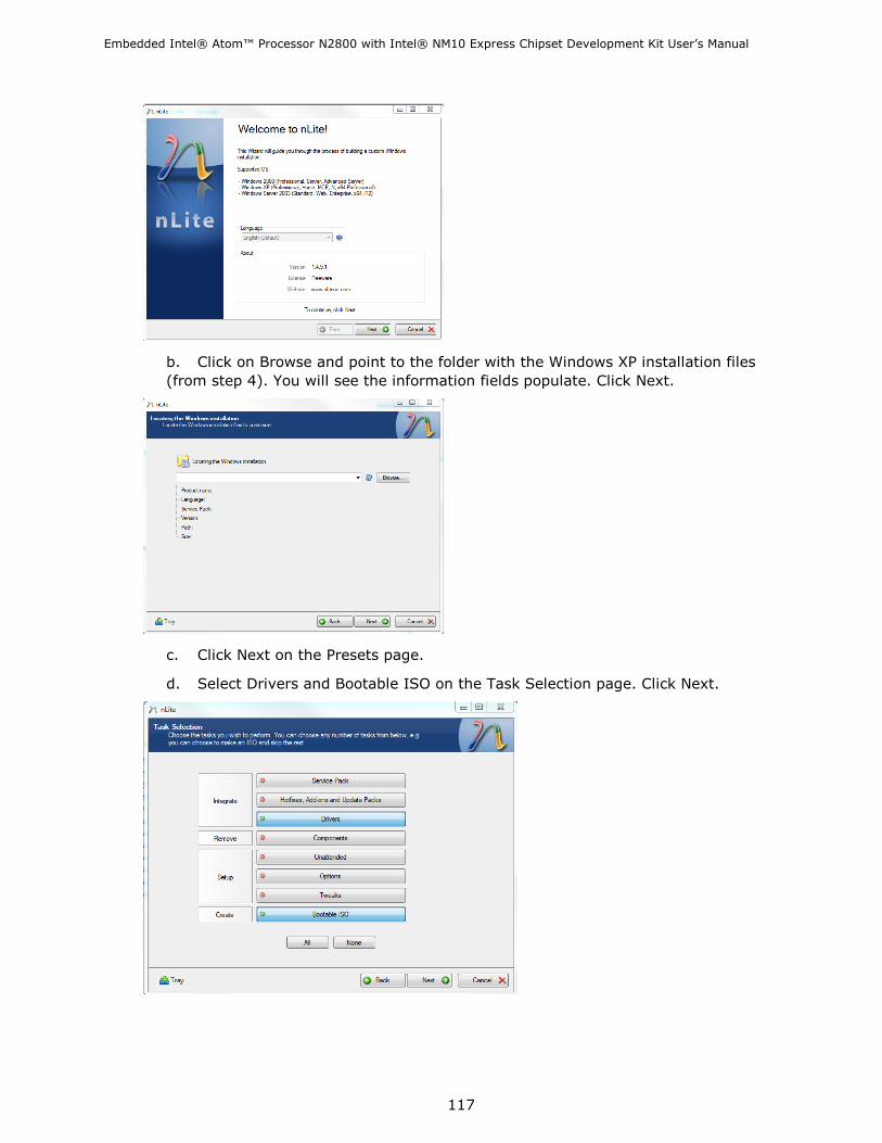
Embedded Intel® Atom™ Processor N2800 with Intel® NM10 Express Chipset Development Kit User‘s Manual
117
b. Click on Browse and point to the folder with the Windows XP installation files
(from step 4). You will see the information fields populate. Click Next.
c. Click Next on the Presets page.
d. Select Drivers and Bootable ISO on the Task Selection page. Click Next.

Embedded Intel® Atom™ Processor N2800 with Intel® NM10 Express Chipset Development Kit User‘s Manual
118
e.
i. Browse to the Intel Rapid Storage Technology F6 Driver files.
ii. Select the iaAHCI.inf file.
f. Select the Textmode driver radio button.
g. Select the Intel® NM10 Express Chipset in the Textmode integration options
pane.
h. Click OK.
i. On the Drivers page, click Next.
j. Click Yes to start the process.
k. On the Processing… page, click Next.
l. On the Bootable ISO page, .abel your new Windows XP installation with
something meaningful such as: WindowsXPSP3NM10SATA.
m. Click Make ISO.

Embedded Intel® Atom™ Processor N2800 with Intel® NM10 Express Chipset Development Kit User‘s Manual
119
n. Name your ISO with a meaningful name, such as:
WindowsXPSP3WithNM10Sata.iso
o. Click Next.
p. Click Finish.
6. Burn the newly generated ISO file to a CD using your favorite tool.
7. Attach a SATA CD ROM or USB CD ROM to Intel‘s CRB.
8. Install Windows XP by selecting the appropriate options in the setup screens.
7.4.4 Install Device Drivers
The Rapid Storage Technology Drivers, Audio Drivers, LAN Drivers, and Chipset Drivers
can be found here:
http://downloadcenter.intel.com/SearchResult.aspx?lang=eng&ProductFamily=Deskto
p+Boards&ProductLine=Intel%c2%ae+NM10+Chipset+Family+Boards&ProductProduct
=Intel%c2%ae+Desktop+Board+DN2800MT&DownloadType=Drivers
7.4.5 Install and configure EMGD
The Intel® Embedded Media and Graphics Driver (Intel® EMGD) comprises a suite of
multi-platform graphics drivers designed to meet the requirements of embedded
applications, featuring Intel® Dynamic Display Configuration Technology (DDCT).
The Intel® Embedded Media and Graphics Drivers support the following types of
display devices:
Analog CRT
LVDS flat panels
HDMI / DVI
DisplayPort / Embedded DisplayPort

Embedded Intel® Atom™ Processor N2800 with Intel® NM10 Express Chipset Development Kit User‘s Manual
120
Intel® EMGD is designed to work with fixed-function systems, such as Point-of-Sale
(POS) devices, ATMs, gaming devices, In-vehicle Information/Entertainment systems,
etc. It can be configured to work with various hardware and software systems.
For more information, please refer to the EMGD User‘s Guide bundled with the EMGD
Graphics Driver.
7.5 Using MeeGo*
This section provides step-by-step instructions for downloading, installing, and
configuring MeeGo for the Intel® Atom™ Processor N2600/D2700/N2800.
These step-by-step instructions have been used with the Intel Customer Reference
Board (CRB) and are applicable to any Intel platform based on the Intel Atom
Processor N2600/D2700/N2800 paired with Intel NM10 Express Chipset.
For customers evaluating or using the Development Kit as a basis for their embedded
design, and MeeGo* as their operating system, this is the primary guidance Intel
provides for setting up the drivers and operating system.
7.5.1 Booting MeeGo*
The MeeGo* project provides a Linux-based, open source software platform for the
next generation of computing devices. The MeeGo software platform is designed to
give developers the broadest range of device segments to target for their applications,
including netbooks, handheld computing and communications devices, in-vehicle
infotainment devices, smart TVs, tablets and more – all using a uniform set of APIs
based on Qt. For consumers, MeeGo will offer innovative application experiences that
they can take from device to device. For more information, visit the MeeGo website at
https://meego.com/.
7.5.2 Live Image on USB stick
1. Insert and Format the USB stick.
a. On Windows 7, right click on Computer.
b. Click on Manage.
c. On the Computer Management page, Select Storage>Disk Management
on the Left hand side
d. Remove any partitions or volumes. This is particularly important when
you have used the USB stick for other Linux distributions or previous
versions of MeeGo.
2. Download the Beta MeeGo image.
a. http://download.meego.com/snapshots/latest-cedartrail/images/meego-
netbook-ia32/
b. Choose the meego-netbook-ia32-*.img file

Embedded Intel® Atom™ Processor N2800 with Intel® NM10 Express Chipset Development Kit User‘s Manual
121
3. Download and install Win32 Disk Imager from:
a. https://launchpad.net/win32-image-writer/+download
4. Use Win32DiskImager to put the image on your USB Stick
5. Write the image to the USB stick by selecting Write.
6. Insert the USB stick into the CRB.
7. When you boot the BIOS be sure to select the USB stick as the primary boot drive.
8. When the selection options appear, select the first option to Boot MeeGo.
7.5.3 Install with USB stick
1. Insert and format the USB stick.
a. On Windows 7, right click on Computer.
b. Click on Manage.
c. On the Computer Management page, Select Storage>Disk Management on the
left hand side
d. Remove any partitions or volumes. This is particularly important when you
have used the USB stick for other Linux distributions or previous versions of MeeGo.
2. Download the Beta MeeGo image.
a. http://download.meego.com/snapshots/latest-cedartrail/images/meego-
netbook-ia32/
b. Choose the meego-netbook-ia32-*.img file
3. Download and install Win32 Disk Imager from:
a. https://launchpad.net/win32-image-writer/+download
4. Use Win32DiskImager to put the image on your USB Stick

Embedded Intel® Atom™ Processor N2800 with Intel® NM10 Express Chipset Development Kit User‘s Manual
122
5. Write the image to the USB stick by selecting Write.
6. Insert the USB stick into the CRB.
7. When you boot the BIOS be sure to select the USB stick as the primary boot drive.
8. When the selection options appear, select the second option to Installation Only
option.
9. Follow the prompts to install.
Note: MeeGo Bug number 23757 has been created recently due to a mismatch size of
the GUI installer when BOTH the VGA and LVDS screens are attached. If you do not
see the arrows or next buttons on the screen, you may press enter as the next buttons
will be enabled by default. Or you can attach just one monitor for the installation
procedure, and the GUI installer should size correctly.
7.5.4 Graphics Driver
The MeeGo Graphics driver is integrated into the MeeGo Alpha image. Since the
graphics capabilities are integrated in the image, no additional installations are
required, and no additional configuring is required to benefit from the Linux based
hardware accelerated graphics drivers. The source file for the stand alone files for the
graphics drivers in MeeGo are at:
http://download.meego.com/live/MeeGo:/1.2.0:/CedarTrail:/
7.5.5 Flash
Hardware accelerated flash for MeeGo can be downloaded from the following site:
https://registrationcenter.intel.com/RegCenter/ComForm.aspx?ProductID=1618.
7.6 Using Yocto Project*
This section provides step-by-step instructions for downloading the drivers for
platforms featuring the Intel® NM10 chipset and the Embedded Graphics Driver for the
Intel® Atom™ Processor N2600/D2700/N2800, to properly install and configure the
Yocto Project*.
The step-by-step instructions in this section have been used with the Intel Customer
Reference Board (CRB). The information in this quick start guide is applicable to any

Embedded Intel® Atom™ Processor N2800 with Intel® NM10 Express Chipset Development Kit User‘s Manual
123
Intel platform based on the Intel Atom Processor N2600/D2700/N2800 paired with
Intel NM10 Express Chipset.
For customers evaluating or using the Development Kit as a basis for their embedded
design, and Yocto Project * to develop a custom Linux* operating system, this is the
primary guidance Intel provides for setting up the drivers and operating system.
7.6.1 Booting Yocto Project*
The Yocto Project* is an open source collaboration project that provides templates,
tools and methods to help you create custom Linux-based systems for embedded
products regardless of the hardware architecture. The Yocto Project* BSP used in this
quick start guide is a custom Linux-based BSP that was generated using the Yocto
Project* tools and methods. See http://www.yoctoproject.org/ for more information.
7.6.2 Live Image on USB stick
1. Insert and Format the USB stick.
a. On Windows 7, right click on Computer.
b. Click on Manage.
c. On the Computer Management page, Select Storage>Disk Management on the
Left hand side
d. Remove any partitions or volumes on the USB Stick. This is particularly
important when you have used the USB stick for other Linux distributions or
previous versions of Yocto Project*.
2. Download the Yocto Project* image.
a. http://www.yoctoproject.org/download/bsp/intel%C2%AE-atom%E2%84%A2-
processor-n2000-and-d2000-series-based-platform-cedar-trail
3. The image (and other supporting files) will be contained within a TAR.BZ2 (also
known as a tarball) archive. Use the latest version of WinZip or 7-Zip to extract the
image.
a. The image filename should be similar to the following:
core-image-sato-cedartrail.hdd.img
b. If necessary change the file extension to .IMG.
4. Download and install Win32 Disk Imager from:
a. https://launchpad.net/win32-image-writer/+download
5. Use Win32DiskImager to put the image on your USB Stick
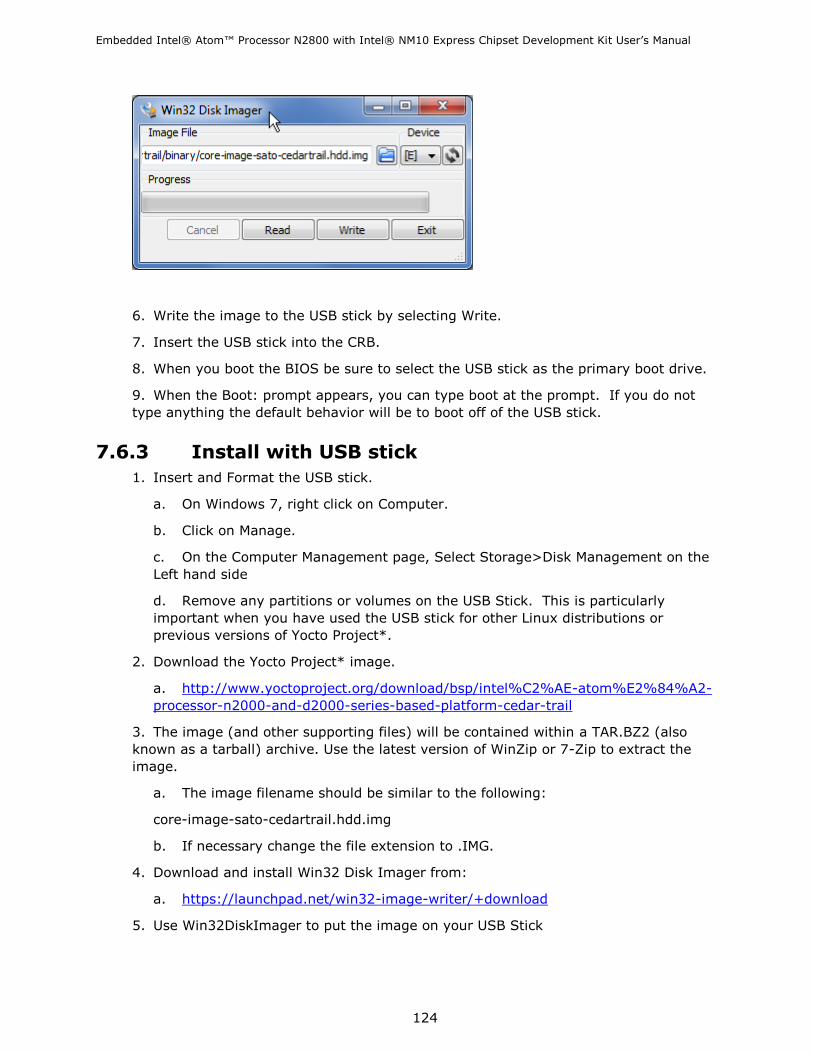
Embedded Intel® Atom™ Processor N2800 with Intel® NM10 Express Chipset Development Kit User‘s Manual
124
6. Write the image to the USB stick by selecting Write.
7. Insert the USB stick into the CRB.
8. When you boot the BIOS be sure to select the USB stick as the primary boot drive.
9. When the Boot: prompt appears, you can type boot at the prompt. If you do not
type anything the default behavior will be to boot off of the USB stick.
7.6.3 Install with USB stick
1. Insert and Format the USB stick.
a. On Windows 7, right click on Computer.
b. Click on Manage.
c. On the Computer Management page, Select Storage>Disk Management on the
Left hand side
d. Remove any partitions or volumes on the USB Stick. This is particularly
important when you have used the USB stick for other Linux distributions or
previous versions of Yocto Project*.
2. Download the Yocto Project* image.
a. http://www.yoctoproject.org/download/bsp/intel%C2%AE-atom%E2%84%A2-
processor-n2000-and-d2000-series-based-platform-cedar-trail
3. The image (and other supporting files) will be contained within a TAR.BZ2 (also
known as a tarball) archive. Use the latest version of WinZip or 7-Zip to extract the
image.
a. The image filename should be similar to the following:
core-image-sato-cedartrail.hdd.img
b. If necessary change the file extension to .IMG.
4. Download and install Win32 Disk Imager from:
a. https://launchpad.net/win32-image-writer/+download
5. Use Win32DiskImager to put the image on your USB Stick

Embedded Intel® Atom™ Processor N2800 with Intel® NM10 Express Chipset Development Kit User‘s Manual
125
6. Write the image to the USB stick by selecting Write.
7. Insert the USB stick into the CRB.
8. When you boot the BIOS be sure to select the USB stick as the primary boot drive.
9. When the Boot: prompt appears, you must type install to install to the attached
SATA drive.
a. Note this prompt only remains on the screen for a few seconds, so you need to
be prepared for it.
10. You will be asked to confirm the drive you intend to install the Yocto Project*
bits on. Type ‗Y‘ at the prompt to complete the installation to the drive.
Note: The Yocto Project* install will assume the entre drive will be used for Project.
Dual boot options, discovery of existing partitions and OSs are not enabled.
7.6.4 Install with CD or DVD
Currently, installing Yocto Project* via CD or DVD is not enabled.
7.6.5 Graphics Driver
The preliminary Yocto Project* BSP graphics driver will be based on the standard Linux
VESA driver. This VESA driver will not be able to take advantage of Intel‘s graphics
engine. Closed source hardware accelerated graphics drivers will be incorporated into
future releases of the Yocto Project BSP.

Embedded Intel® Atom™ Processor N2800 with Intel® NM10 Express Chipset Development Kit User‘s Manual
126
8 Battery Disposal Information
CAUTION Risk of explosion if the battery is replaced with an incorrect type. Batteries should be
recycled where possible. Disposal of used batteries must be in accordance with local
environmental regulations.
PRÉCAUTION
Risque d'explosion si la pile usagée est remplacée par une pile de type incorrect. Les
piles usagées doivent être recyclées dans la mesure du possible. La mise au rebut des
piles usagées doit respecter les réglementations locales en vigueur en matière de
protection de l'environnement.
FORHOLDSREGEL
Eksplosionsfare, hvis batteriet erstattes med et batteri af en forkert type. Batterier bør
om muligt genbruges. Bortskaffelse af brugte batterier bør foregå i overensstemmelse
med gældende miljølovgivning.
OBS!
Det kan oppstå eksplosjonsfare hvis batteriet skiftes ut med feil type. Brukte batterier
bør kastes i henhold til gjeldende miljølovgivning.
VIKTIGT!
Risk för explosion om batteriet ersätts med felaktig batterityp. Batterier ska kasseras
enligt de lokala miljövårdsbestämmelserna.
VARO
Räjähdysvaara, jos pariston tyyppi on väärä. Paristot on kierrätettävä, jos se on
mahdollista. Käytetyt paristot on hävitettävä paikallisten ympäristömääräysten
mukaisesti.
VORSICHT
Bei falschem Einsetzen einer neuen Batterie besteht Explosionsgefahr. Die Batterie
darf nur durch denselben oder einen entsprechenden, vom Hersteller empfohlenen
Batterietyp ersetzt werden. Entsorgen Sie verbrauchte Batterien den Anweisungen des
Herstellers entsprechend.
AVVERTIMENTO
Esiste il pericolo di un esplosione se la pila non viene sostituita in modo corretto.
Utilizzare solo pile uguali o di tipo equivalente a quelle consigliate dal produttore. Per
disfarsi delle pile usate, seguire le istruzioni del produttore.

Embedded Intel® Atom™ Processor N2800 with Intel® NM10 Express Chipset Development Kit User‘s Manual
127
PRECAUCIÓN
Existe peligro de explosión si la pila no se cambia de forma adecuada. Utilice
solamente pilas iguales o del mismo tipo que las recomendadas por el fabricante del
equipo. Para deshacerse de las pilas usadas, siga igualmente las instrucciones del
fabricante.
WAARSCHUWING
Er bestaat ontploffingsgevaar als de batterij wordt vervangen door een onjuist type
batterij. Batterijen moeten zoveel mogelijk worden gerecycled. Houd u bij het
weggooien van gebruikte batterijen aan de plaatselijke milieuwetgeving.
ATENÇÃO
Haverá risco de explosão se a bateria for substituída por um tipo de bateria incorreto.
As baterias devem ser recicladas nos locais apropriados. A eliminação de baterias
usadas deve ser feita de acordo com as regulamentações ambientais da região.
AŚCIAROŽZNAŚĆ
Існуе рызыка выбуху, калі заменены акумулятар неправільнага тыпу.
Акумулятары павінны, па магчымасці, перепрацоўвацца. Пазбаўляцца ад старых
акумулятараў патрэбна згодна з мясцовым заканадаўствам па экалогіі.
UPOZORNÌNÍ
V případě výměny baterie za nesprávný druh může dojít k výbuchu. Je-li to možné,
baterie by měly být recyklovány. Baterie je třeba zlikvidovat v souladu s místními
předpisy o životním prostředí.
Προσοχή
Υπάπσει κίνδςνορ για έκπηξη ζε πεπίπηυζη πος η μπαηαπία ανηικαηαζηαθεί από μία
λανθαζμένος ηύπος. Οι μπαηαπίερ θα ππέπει να ανακςκλώνονηαι όηαν κάηι ηέηοιο είναι
δςναηό. Η απόππιτη ηυν σπηζιμοποιημένυν μπαηαπιών ππέπει να γίνεηαι ζύμθυνα με
ηοςρ καηά ηόπο πεπιβαλλονηικούρ κανονιζμούρ.
VIGYÁZAT
Ha a telepet nem a megfelelő típusú telepre cseréli, az felrobbanhat. A telepeket
lehetőség szerint újra kell hasznosítani. A használt telepeket a helyi környezetvédelmi
előírásoknak megfelelően kell kiselejtezni.
Embedded Intel® Atom™ Processor N2800 with Intel® NM10 Express Chipset Development Kit User‘s Manual
128
AWAS
Risiko letupan wujud jika bateri digantikan dengan jenis yang tidak betul. Bateri
sepatutnya dikitar semula jika boleh. Pelupusan bateri terpakai mestilah mematuhi
peraturan alam sekitar tempatan.
OSTRZEŻENIE
Istnieje niebezpieczeństwo wybuchu w przypadku zastosowania niewłaściwego typu
baterii. Zużyte baterie należy w miarę możliwości utylizować zgodnie z odpowiednimi
przepisami ochrony środowiska.
PRECAUŢIE
Risc de explozie, dacă bateria este înlocuită cu un tip de baterie necorespunzător.
Bateriile trebuie reciclate, dacă este posibil. Depozitarea bateriilor uzate trebuie să
respecte reglementările locale privind protecţia mediului.
ВНИМАНИЕ
При использовании батареи несоответствующего типа существует риск ее взрыва.
Батареи должны быть утилизированы по возможности. Утилизация батарей должна
проводится по правилам, соответствующим местным требованиям.
UPOZORNENIE
Ak batériu vymeníte za nesprávny typ, hrozí nebezpečenstvo jej výbuchu.
Batérie by sa mali podľa možnosti vždy recyklovať. Likvidácia použitých batérií sa musí
vykonávať v súlade s miestnymi predpismi na ochranu životného prostredia.
POZOR
Zamenjava baterije z baterijo drugačnega tipa lahko povzroči eksplozijo.
Če je mogoče, baterije reciklirajte. Rabljene baterije zavrzite v skladu z lokalnimi
okoljevarstvenimi predpisi.
UYARI
Yanlış türde pil takıldığında patlama riski vardır. Piller mümkün olduğunda geri
dönüştürülmelidir. Kullanılmış piller, yerel çevre yasalarına uygun olarak atılmalıdır.
OСТОРОГА
Використовуйте батареї правильного типу, інакше існуватиме ризик вибуху.
Якщо можливо, використані батареї слід утилізувати. Утилізація використаних
батарей має бути виконана згідно місцевих норм, що регулюють охорону довкілля.

Embedded Intel® Atom™ Processor N2800 with Intel® NM10 Express Chipset Development Kit User‘s Manual
129