Embed Size (px)
Citation preview

ALISPANAssembly Instructions - Hip End
New Zealand52 Newton Street, PO Box 4370, Mount MaunganuiNew Zealand
tel +64 7 579 0190fax +64 7 579 0194 www.baytex.-co.nz
Australiatel 02 4340 4144mob 0400 312 314
Use the Spacer Bar to position the first two Base Plates.
Set out the width of the first Portal. Measure the Portal width from centre to centre.
Check the diagonals - they must be approximatelyequal to each other.
Securely attachthe Brace Cables.
Connect the legto rafter.
Set up the string line.
1 2
3 4
5 6
7 8
9 10
INSTALL SET UP
ASSEMBLE PORTALS
Assemble each Portal frame - at least one mid and addHip Ends later. Attach to Base Plates. Secure both Portal Brace Stays to the adjacent Base Plates.

Lift the first Portal with everyonestarting at the middle. As thePortal is raised the crew shouldmove outwards.
Hold the Portal securely in thenot quite vertical position.
Engage the Ridge Purlinhook end first.
Raise the second Portal and rest on the Push Pole.
First portal brace cables.
IMPORTANT: All Brace Cables must be properly fittedinto a single bay as shown.
Lightly tighten all the Brace Cables.
RAISE PORTALS
FIT BRACE CABLES
12
13 14
15 16
17 18
19 20
Use the Purlin Fork to engagethe Ridge Purlin & Intermediatepurlins into the next portal.
11
Attach the Push Pole and check that the Retaining Clip and Cord are secure.
Secure first portal brace stays before standing second portal.
Fit eaves both sides.
Continue to raise the remaining Portals by repeating the process. A set of Brace Cables is only required on every fifth bay. At this point all Base Plates must be firmly fixed down,
ballasted or staked with the required number of stakes.
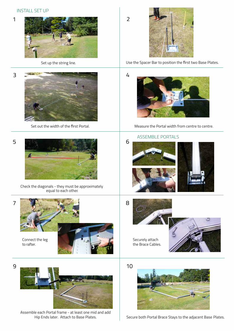
Remove the Brace Stays only when all the cables are securely fitted.
21 22
Attach first hip side rafter.
HIP END INSTALL
Use lifting fork to lift hip side rafter into place
Repeat second hip side rafter.
Attach hip end eave rail.
Insert leg tohip side rafter.
Attach hip end eave rail.
Insert leg to eave,and attach hip side rafter.
Attach hip end rafter.
Insert leg tohip end rafter.
Attach all eave rails.
23 24
25 26
27 28
29 30
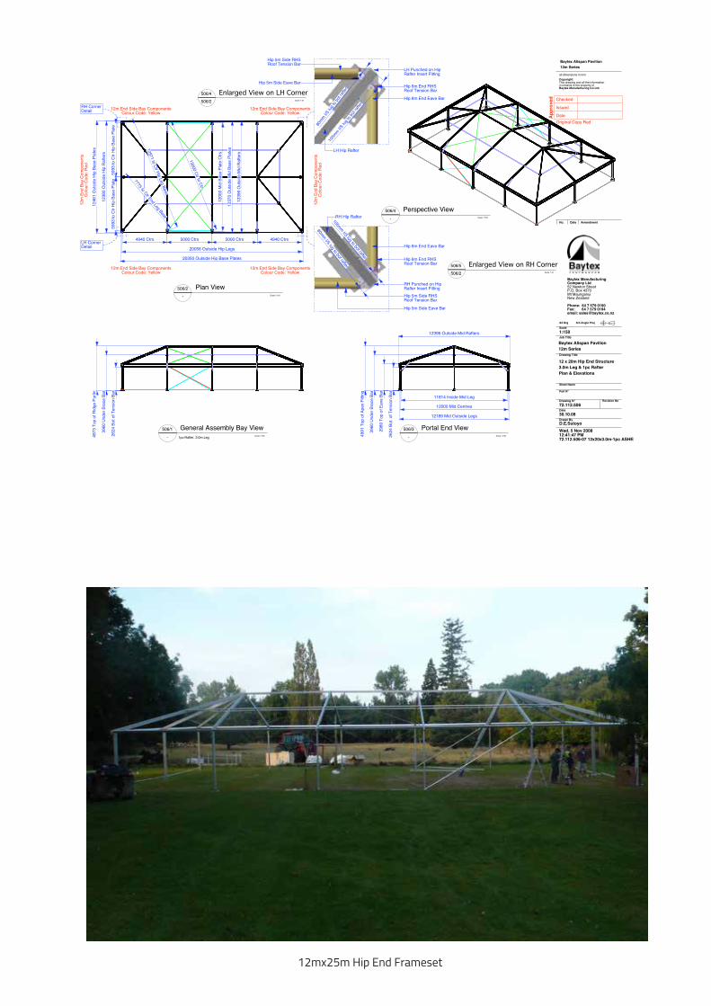
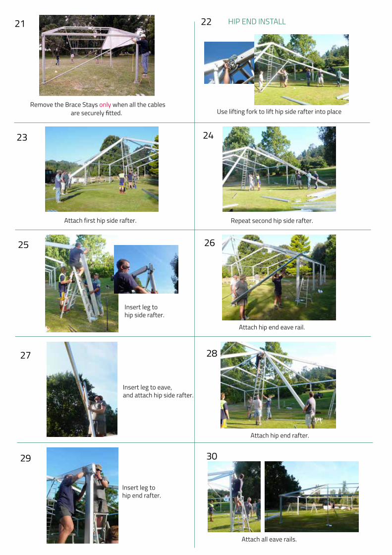
12mx25m Hip End Frameset
Wed, 5 Nov 200812:41:47 PM72.112.506-07 12x20x3.0m-1pc ASHEPrtList
Checked
Ap
pro
ve
d
Original Copy Red
Issued
Date
No. Date Amendment
Baytex Manufacturing Company Ltd52 Newton Street P.O. Box 4370Mt MaunganuiNew Zealand
Phone: 64 7 579 0190Fax: 64 7 579 0194email: [email protected]
Scale
Job Title
Drawn By
Drawing N°
Date
Drawing Title
A3 Drg 3rd Angle Proj
Part N°
Revision No
D.E.Sutoyo
all dimensions in mm
Sheet Name
Baytex Alispan Pavilion
1:150
Baytex Alispan Pavilion
12 x 20m Hip End Structure
72.112.506
30.10.08
12m Series
3.0m Leg & 1pc Rafter
12m Series
Plan & Elevations
Copyright: This drawing and all the information it contains is the property of Baytex Manufacturing Co Ltd.
12396 O
uts
ide M
id R
afters
12370 O
uts
ide M
id B
ase P
late
s
7775 to Ctr E
nd Leg Base
12971 to
Ctr H
ip L
eg B
ase
12000 M
id B
ase P
late
Ctr
s
4940 Ctrs 5000 Ctrs 4940 Ctrs
13000 C
tr to C
tr
5993 to C
tr H
ip B
ase P
late
5993 to C
tr H
ip B
ase P
late
12380 O
uts
ide H
ip R
afters
12461 O
uts
ide H
ip B
ase P
late
s
20056 Outside Hip Legs
20350 Outside Hip Base Plates
5000 Ctrs
Plan ViewScale 1:150
506/2
-
12m End Side Bay ComponentsColour Code: Yellow
12m
End B
ay C
om
ponents
Colo
ur
Code: R
ed
12m End Side Bay ComponentsColour Code: Yellow
12m
End B
ay C
om
ponents
Colo
ur
Code: R
ed
12m End Side Bay ComponentsColour Code: Yellow
12m End Side Bay ComponentsColour Code: Yellow
RH Corner Detail
LH Corner Detail
General Assembly Bay ViewScale 1:150
506/1
- 1pc Rafter, 3.0m Leg4973 T
op o
f R
idge P
urlin
3960 U
nder
Bra
ce B
ar
2624 B
ot of T
ensio
n B
ar
12000 Mid Centres
12189 Mid Outside Legs
12396 Outside Mid Rafters
11814 Inside Mid Leg
Portal End ViewScale 1:150
506/3
-4991 T
op o
f A
pex F
itting
3960 U
nder
Bra
ce B
ar
2989 T
op o
f E
ave B
ar
2624 B
ot. o
f T
ensio
n B
ar
Perspective ViewScale 1:150
506/4
-
Hip 6m End Eave Bar
Hip 5m Side Eave Bar
LH Punched on Hip Rafter Insert Fitting
LH Hip Rafter
Scale 1:10
Enlarged View on LH Corner506/4
506/2
Hip 6m End RHS Roof Tension Bar
Hip 5m Side RHSRoof Tension Bar
80m
m I/
S lu
g to
bot
rafte
r
105m
m I/
S lu
g to
bot
rafte
r
Hip 6m End Eave Bar
Hip 5m Side Eave Bar
RH Punched on Hip Rafter Insert Fitting
RH Hip Rafter
Scale 1:10
Enlarged View on RH Corner506/5
506/2
Hip 6m End RHS Roof Tension Bar
Hip 5m Side RHS Roof Tension Bar
80mm
I/S lug to bot rafter
105mm
I/S lug to bot rafter

Engage one end of the Roof Panel into both Keder grooves. Use the Pull Ropes to slide the roof panels into position - pull both ropes together making sure that both
crew pull evenly.
INSTALLING ROOF PANELS31
Install the Roof Tension Bars and tension evenly.
32
34
Install each Wall by sliding the Slugs into the bottom track of the Eave Bar.
33 INSTALLING WALLS
No. Date Amendment
Baytex Manufacturing Company Ltd52 Newton Street P.O. Box 4370Mt MaunganuiNew Zealand
Phone: 64 7 579 0190Fax: 64 7 579 0194email: [email protected]
Scale
Job Title
Drawn By
Drawing N°
Date
Drawing Title
A3 Drg 3rd Angle Proj
Part N°
Revision No
D.E.Sutoyo
all dimensions in mm
Sheet Name
Baytex Alispan Pavilion
1:100
Baytex Alispan Pavilion
12 x 20m Hip End Structure
72.112.507
30.10.08
12m Series
3.0m Leg & 1pc Rafter
12m Series
Parts List
Copyright: This drawing and all the information it contains is the property of Baytex Manufacturing Co Ltd.
Wed, 5 Nov 200812:41:47 PM72.112.506-07 12x20x3.0m-1pc ASHEPrtList
Checked
Ap
pro
ve
d
Original Copy Red
Issued
Date
4
5
9
19
16
11
20
1213
14
27
26
10
24
8
6
2
3
D
B
C
A
15
27
22
4
21
9
23
18
7
25
17
1
HardwarePart Name Qty Drawing Number
1 12m AliSpan Rafter Assy - 1pc 8 72.512.019
2 12m AliSpan Hip End Rafter Assy 4 72.512.019
3 12m AliSpan Hip Side Rafter Assy - 2pc 6 72.512.019
4 Alispan Purlin - Eave/Apex 5m Centre Slot 6 72.722
5 Alispan Purlin - Intermediate 5m 4 72.721
6 Alispan Purlin - Intermediate Hip End 4 72.512.121
7 Alispan Purlin - Intermediate Hip Side 4 72.512.120
8 Apex Hip Attachment 2 72.512.101
9 Apex Insert Assy (Std) 3 72.710
10 Base Fitting with Pin - Side 12 72.701
11 Base Rail 5m Centres 4 72.704
12 Base Rail - 12m Hip Side 4 72.512.118
13 Base Rail - 12m Hip End 4 72.512.119
14 Brace Cable Set (Roof) (4x per set) 1 72.512.008
15 Brace Cable Set (Wall) (4x per set) - 3.0m Leg 1 72.738
16 Eave Bar Assy - Hip End 4 72.512.115
17 Eave Bar Assy - Hip Side 4 72.512.114
18 Knee Brace 6 72.770
19 Leg Assembly - 3.0 Braced Hip Corner 2 72.512.109
20 Leg Assembly - 3.0 Braced Hip End 4 72.512.112
21 Leg Assembly - 3.0 Braced Side 6 72.735
22 Mid Portal Set Up Brace Bar 5m - 3.0m Leg 2 72.745
23 Tension Bar 5m Mid 4 72.715
24 Tension Bar - 12m Hip End 4 72.512.117
25 Tension Bar - 12m Hip Side 4 72.512.116
26 Tension Bracket - Hip Corner 4 72.729
27 Tension Bracket - Mid 8 72.717
FabricPart Name Quantity Drawing Number
A 12m Roof Mid 2 72.312.200
B 12m Pr Hip End Roof 1 72.312.330
C 5m Bay Wall - 3.0m Leg 8 72.301
D 6m Gable Wall - 3.0m Leg 4 72.312.1000
Pull the hip end roofs over with ropes.

Repeat for both sections of each Wall.Slide the side of each Wall section into the outside Keder Track of the Leg Extrusion.
35 36
Slide the Wall Bars in from the outside.
3837
Lace walls together.
12mx25m Hip End complete.


![Appendix 1 HIP Male and Female - University of East Anglia · App14.1!HIP!v3.2_02_05_2012!!!!!Health’Improvement’Profile[HIP]’ ’’’’’’’’’’’’’’’’’’’’’’’’’’’’(HIP)–’Male](https://img.dokumen.tips/doc/110x75/5f0af26b7e708231d42e1f1c/appendix-1-hip-male-and-female-university-of-east-anglia-app141hipv3202052012healthaimprovementaprofilehipa.jpg)


![Assembly System Design Issues - [email protected]](https://img.dokumen.tips/doc/110x75/61fb73d02e268c58cd5e55d2/assembly-system-design-issues-emailprotected.jpg)