Embed Size (px)
Citation preview

Yarmouk University
Hijjawi Faculty For Engineering Technology
Electronics Engineering Department
Comatic Jordan Company
Al-Ameer Rashid Bin AL Hassan
Hospital
Prepared By:
Emad Mohammad Adnan Otoum
(2010972101)
Supervised By:
Eng. Ma'mon Al-Tantawi
2014

Acknowledgements I would give my thanks for everyone who assisted me in preparing my field training report.
I am greatly indebted to Eng. Ma'mon Al-Tantawi for his continues supervision, and guidance during training duration.
Also deep of thanks for technical staff in Prince Rashed Bin AL-Hassan hospital and Comatec Jo. for their collaboration and patience to give me their experiences especially in device maintenance. To my parents , who stood beside me throughout my life , and to whom I will be indebted forever, also to my brothers and sisters for their understanding , patience and encouragement that have been given to me.

Abstract
This report was prepared for the graduation requirement of our engineering
faculty. Each student has a practical training period for about six month in one
of the relied institution from our college. The period training is the most
important period in our studying plan, it forms the character of the engineer so
we must improve our skills and knowledge in field training.
My first training period in extends from 15/1 to 1/4/2014 in comatec Jordan in
amman and my second training period in extends from 2/4 to 2/8/2014 in
Prince Rashid Bin Al-Hassan Military hospital.
About Comatec
Comatec Group is one of the leading companies in Telecom deployment and
Civil works that started 1989 in Jordan. Today the company operate in 6
countries (Jordan, Lebanon, Cyprus, Egypt, KSA and Malta). Comatec have
two different Telecom segments; namely Telecom Civil work deployment and
Telecom operation. It have more than 300 Telecom professionals with
extensive hands-on Telecom and IT experience in mutli-technologies.
About Princess Rashid Bin Al hassan
Hospital
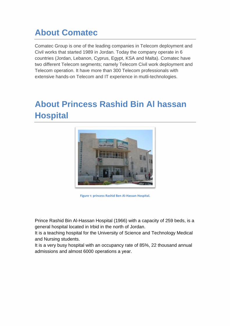
Figure 1: princess Rashid Ben Al-Hassan Hospital.
Prince Rashid Bin Al-Hassan Hospital (1966) with a capacity of 259 beds, is a
general hospital located in Irbid in the north of Jordan.
It is a teaching hospital for the University of Science and Technology Medical
and Nursing students.
It is a very busy hospital with an occupancy rate of 85%, 22 thousand annual
admissions and almost 6000 operations a year.

Table Of Contents
Table of figure Acknowledgements Abstract About Chapter one: Background Information ....................................................................................... 1
1.1 Introduction ................................................................................................................... 1
1.2 GSM Architecture Overview ........................................................................................... 1
1.2.1 The GSM Mobile Station(MS): .................................................................................... 2
1.2.2 The Basic Station Subsustem ................................................................................... 3
1.2.3 The Network Switching System (NSS) ....................................................................... 5
Chapter Two: Medical Devices And Equipments……………………………………………9
2.1 Basic Type Of Medical Device: .......................................................................................10
2.2 Radiology Or Imaging Group: .........................................................................................11
2.2.1 X-ray Machine ...........................................................................................................12
2.3 MRI (Magnetic Resonance Imaging) ..................................................................................15
2.3.1 The Major Components Of MRI ....................................................................................16
2.4 ICU Equipments ..................................................................................................................18
2.4.1 Patient Monitor ..........................................................................................................18
2.4.2 Blood Pressure .........................................................................................................19
2.4.3 Electrocardiogram (ECG) ..........................................................................................20
2.4.4 Pulse Oximetry (SPO2).............................................................................................21
2.5 Neuro-Electrophysiology Department ..................................................................................24
2.5.1 EEG (Electroncephalogram) .....................................................................................24
2.5.2 ECG (Electrocardiogram) ..........................................................................................18
Chapter Three: Work Shop ............................................................................................................. 34
3.1 Types of Maintenance: ........................................................................................................27
3.1.1 How To Test Some Electroparts ................................................................................28
Conclusion References

Table of figure
Fig 1 : GSM Architecture………………………………………………………………….….………..1
Fig 2: BSS comprises………………………………………………………………………….…….....4
Fig 3: Key elements of the NSS…………………………………………………………….………...6
Figure 4: functional components for instrumentation system……………………….……….11
Figure 5: Radiology or Imaging Example..……………………………………………….……….12
Figure 6: a- X-Ray device…………………………………………………………………………….13
Figure 7: x-ray tube components………………………………………………………..………….14
Figure 8: x-ray tube housing……………………………………………………………..………….16
Figure 9: MRI Scanner with components …………………………………………………..…….18
Figure 10: Block diagram of a patient monitor. ………………………………………………….19
Figure 11: Block diagram of a blood-pressure system…………………………………………21
Figure 12: Block diagram of an ECG system. ……………………………………………………22
Figure 13: Block diagram for pulse oximetry system……………………………………..……23
Figure 14: patients monitor display……………………………………………………………..…26
Figure 15: ECG signal. ………………………………………………………………………….…....29
Figure 16: Color code…………………………………………………………………………………29
Figure 17: capacitor. ……………………………………………………………………………….…30
Figure 18 :Voltage Regulator……………………………………………………………………..…31
Figure 19: Relays…………………………………………………………………………………...….32

1
Chapter one
BBaacckkggrroouunndd iinnffoorrmmaattiioonn.
1.1 Introduction:
The aim of a GSM (Global system for mobile communication) system is to make best use of the available frequencies to provide:
• Coverage: getting a usable radio signal to all areas in the network
• Capacity: handling the call traffic generated by the subscribers
• Quality: low interference, few calls dropped etc
1.2 GSM Architecture Overview:
Fig 1 : GSM Architecture
A GSM network is made up of three subsystems:
• The Mobile Station (MS).

2
• The Base Station Sub-system (BSS): comprising a BSC and several BTSs.
• The Network and Switching Sub-system (NSS): comprising an MSC and
Associated Registers.
There is several interfaces are defined between different parts of the
system:
• 'A' interface between MSC and BSC.
• 'Abis' interface between BSC and BTS.
• 'Um' air interface between the BTS (antenna) and the MS.
1.2.1 The GSM Mobile Station (MS):
The mobile station consists of:
• Mobile equipment (ME).
• Subscriber identity module (SIM).
The SIM stores permanent and temporary data about the mobile, the
subscriber and the network, is including:
• The International Mobile Subscribers Identity (IMSI).
• MS ISDN number of subscriber.

3
• Authentication key (Ki) and algorithms for authentication check.
The two parts of the mobile station allow a distinction between the actual
equipment and the subscriber who is using it. The IMSI identifies the
subscriber within the GSM network while the MS ISDN is the actual telephone
number a caller (possibly in another network) uses to reach that person.
Security is provided by the use of an authentication key and by the
transmission of a temporary subscriber identity (TMSI) across the radio
interface where possible to avoid using the permanent IMSI identity.
The IMEI may be used to block certain types of equipment from accessing the
network if they are unsuitable and also to check for stolen equipment.
1.2.2 The Base Station Subsystem (BSS) :
The BSS comprises:
• Base Transceiver Station (BTS).
• One or more Base Station Controllers (BSC).

4
Fig 2: BSS comprises
The purpose of the BTS is to provide radio access to the mobile stations and
manage the radio access aspects of the system .The BTS contains of Radio
Transmitter/ Receiver (TRX), Signal processing and control equipment, And
Antennas and feeder cables.
The BSC allocates a channel for the duration of a call and maintains the call;
this includes monitoring quality, controlling the power transmitted by the BTS
or MS, and generating a handover to another cell when required.
The effect of gains and losses in the BTS equipment on the signal power sent
to the antenna is an important consideration for link budget calculations.
Planning BTS

5
positions requires a software tool such as Asset. Acquiring sites and
implementing the plan involves a combination of surveying, engineering and
legal work.
Handover in GSM is always ‘hard’ that is the mobile only ever has a
communication link (traffic channel) open with one base station at one time.
This is true of any system with multiple frequencies, since the mobile must
retune at the handover. Single frequency systems (such as CDMA) may use
soft handover.
The quality and power level of the radio link compared with that available from
neighboring cells are important inputs to the handover decision made by the
BSC.
Base stations are linked to the parent BSC in one of several standard network
topologies. The actual physical link may be microwave, optical fiber or cable.
Planning of these links may be done using a tool such as Connect.
1.2.3 The Network Switching System (NSS):
Key elements of the NSS:
• Mobile Switching Centre (MSC) with Visitor Location Register (VLR).
• Home Location Register (HLR) with Authentication Centre (AuC).

6
• Equipment Identity Register (EIR).
• Gateway MSC (GMSC).
Fig 3: Key elements of the NSS
1.2.3.1 Mobile Switching Centre (MSC):
The functions of the MSC is Switching calls, controlling calls and logging calls
, Interface with PSTN, ISDN, PSPDN , Mobility management over the radio
network and other networks , Radio Resource management - handovers
between BSCs , and Billing Information .
Visitor Location Register (VLR):
Each MSC has a VLR and the VLR stores data temporarily for mobiles served
by the
MSC,
the Information stored includes:
• IMSI
• Mobile Station ISDN Number

7
• Mobile Station Roaming Number
• Temporary Mobile Station Identity
• Local Mobile Station Identity
• The location area where the mobile station has been registered
• Supplementary service parameters
Notice that the VLR stores the current Location Area of the subscriber, while
the HLR stores the MSC/VLR they are currently under. This information is
used to page the subscriber when they have an incoming call.
1.2.3.2 Home Location Register (HLR):
The HLR Stores details of all subscribers in the network, such as:
• Subscription information.
• Location information: mobile station roaming number, VLR, MSC.
• International Mobile Subscriber Identity (IMSI).
• MS ISDN number.
• Tele-service and bearer service subscription information.
• Service restrictions.
• Supplementary services.

8
Together with the AuC, the HLR checks the validity and service profile of
subscribers.
HLR Implementation:
There is one HLR in a network, May be split regionally, And he Stores details
of several thousand subscribers, he Stand alone computer - no switching
capabilities, and May be located anywhere on the SS7 network, and he
Combined with AuC.
1.2.3.3 Equipment Identity Register (EIR)
The EIR is a database that stores a unique International Mobile Equipment
Identity (IMEI) number for each item of mobile equipment. And controls
access to the network by returning the status of a mobile in response to an
IMEI query.
The Possible status levels are:
• White-listed: The terminal is allowed to connect to the network.
• Grey-listed: The terminal is under observation by the network for possible
Problems.
• Black-listed: The terminal has either been reported stolen, or is not a type
Approved for a GSM network. The terminal is not allowed to connect to the

9
Network.
The EIR may optionally be used by the operator to control access to the
network by certain types of equipment or to monitor lost or stolen handsets.
1.2.3.4 Gateway Mobile Switching Centre (GMSC):
A Gateway Mobile Switching Centre (GMSC) is a device which routes traffic
entering a mobile network to the correct destination. And he accesses the
network’s HLR to find the location of the required mobile subscriber, and the
particular MSC can be assigned to act as a GMSC , The operator may decide
to assign more than one GMSC.
10
Chapter Two
2 Medical Devices and
equipments
A medical device is “any item promoted for a medical purpose
that does not rely on chemical action to achieve its intended effect” [Medical Device Amendments (Public law 94-295)]
2.1 There are several basic types of medical
devices: There are several basic categories of medical equipment, and medical
equipment suppliers will often manufacture or provide only one category or a
small range of highly specialized equipment and therapies.
Diagnostic equipment includes medical imaging machines, used to aid
in diagnosis. Examples of these are ultrasound and MRI machines,
PET and CT scanners, and x-ray machines.
Therapeutic equipment includes infusion pumps, medical lasers and
LASIK surgical machines.
Life support equipment is used to maintain a patient's bodily function.
This includes medical ventilators, anaesthetic machines, heart-lung
machines, ECMO, and dialysis machines.

11
2.2 Radiology or imaging group
Figure 4: Radiology or Imaging Example.
Radiology is the branch or specialty of medicine that deals with the study and
application of imaging technology like x-ray and radiation to diagnosing or
treating
This group deals with equipments used for radiology, imaging and image
processing such as:
X-ray machine
CT scanners
ultrasound
MRI machine
For an example I will talk briefly about some of these equipments:

12
Figure 5: a- X-Ray device.
2.2.1 X-ray machine
X-rays are electromagnetic radiation (photon) observed when a beam
of electrons strikes a target with wavelengths, 10pm< <10nm.these photons
travel with the speed of light, c=3*10^8m/s.
The X-ray tube contains anode and cathode, the cathode is connected to
a high voltage generator, this cause the cathode to emit electrons with high
speed and energy, this electrons hits the anode causing it to generate X-rays,
the X-rays generated from the tube are restricted by the aperture in the
collimator, the Al filter removes low-energy X-rays that would not penetrate
the body, scattered secondary radiation is trapped by the grid whereas
primary radiation strikes the screen phosphor, the resulting light exposes the
film, the electron beam current is controlled by adjusting the filament current,
with compensation of filament current for variations of anode current
2.2.2 X-Ray Imaging System Components
The x-ray machine is divided into four major components.

13
• The Tube
Figure 6: x-ray tube components
The X-ray tube contains either a filament or cathode emitter that expels
accelerated electrons and leads them to a metal anode, where current is now
flowing. The electrons that have been emitted toward the anode make up an
electron beam. The beam hits a focal point in the anode, where a small
percentage is converted into X-ray photons. The photons are discharged in all
directions, and once the control unit is put to use, the adjusted currents and
voltage result in a beam of X-rays that is projected onto a visible substance.
An X-ray machine essentially acts as a camera, but without the visible light.
Instead, it uses the X-rays that were produced to expose the film. X-rays use
electromagnetic waves that can break through several layers due to the
energy held inside of them. If the body is being X-rayed, the skin tissue will
not absorb the waves coming from the X-ray but the dense parts of the body
will, which is why bones, tendons and ligaments are able to be examined.

14
Figure 7: x-ray tube housing
2.2.3 X-Ray Tube Housing Purposes Decreases leakage radiation to maximum level of 100 mR/hour at a
distance of 1 meter.
Minimizes exposure dose to patient and radiographer.
Provides mechanical support for x-ray tube .
Oil circulates around x-ray tube
Insulator protecting from electric shock
Dissipates heat
Cooling fan
The Operating Console
The operating console is the control unit, which works to manage the currents,
voltage and timer. The current control has a display that allows adjustment of
the tube current to vary radiation intensity. The voltage control also has a
display, allowing adjustments in the anode to change the energy of radiation.
The timer control determines the duration of the exposure; once the time
stops, no more radiation is being produced.
• The High Voltage Section
The high-voltage power supply uses a transformer to accurately alternate
between the voltage of currents being sent to the emitter or to the anode. The
emitter requires a small voltage supply to produce small currents, while the
anode needs a large voltage supply to keep the speed of the electrons up.
The energy of radiation that is produced is dependent on the high speed of
the electrons.

15
2.2.4 Types of X-Ray Equipment Two types:
Diagnostic
therapeutic
The most problems of x-ray machine in general as follow:
Action Cause Problem
1-check cable connection. 2-inspect with DMM.
1-cable is hewn. 2-there is s/c or o.c.
Hand switches doesn’t give exposure.
Check/replace relay/microswitch
Relay /microswitch Table motions
Calibrate shatters by move potentiometer in a proper position.
Shatters Collimator doesn’t give a proper size.
Replace x-ray tube with a new one
x-ray tube defective x-ray tube
Table 1: The most problems of X-Ray machine.
Note: x-ray is dangerous, it cause cancer diseases and it convert H2O to H2 and OH , OH may be link
with another OH to give H2O2 which is acid and this acid may enter in DNA composition. So in
conventional x-ray there is banking system which consist of three champers (right , left , and middle) e.g
if you want to take image for chest, choose right and left champers, but you cann’t choose middle for
spanned column.
2.3 MRI (Magnetic Resonance Imaging): The MRI scan uses magnetic and radio waves, meaning that there is no
exposure to X-rays or any other damaging forms of radiation.
Magnetic Resonance Imaging (MRI) is primarily a medical imaging technique
most commonly used in radiology to visualize detailed internal structure and
limited function of the body. MRI provides much greater contrast between the
different soft tissues of the body than computed tomography (CT) does,
making it especially useful in brain, heart, muscles, and cancer imaging.
Unlike CT, it uses no ionizing radiation, but uses a powerful magnetic field to
align the nuclear magnetization of (usually) hydrogen atoms in water in the
body.

16
Figure 8: MRI Scanner with components
2.3.1 The Major Components of MRI:
gantry:
Magnet: it is a super conductor, for cooling using Helium (He).
Shim: using it for homogenous magnetic field inside the cylinder.
Radio frequency coil.
Gradient coil (for directions x, y, z) : X: left to right, Y: for deep,
Z: foot to head.
Consol.
Couch.
Room cabinet.

17
2.3.2 How does it work: The patient lies inside a large, cylinder-shaped magnet. Radio waves 10,000
to 30,000 times stronger than the magnetic field of the earth are then sent
through the body. This affects the body's atoms, forcing the nuclei into a
different position. As they move back into place they send out radio waves of
their own. The scanner picks up these signals and a computer turns them into
a picture. These pictures are based on the location and strength of the
incoming signals. Our body consists mainly of water, and water contains
hydrogen atoms. For this reason, the nucleus of the hydrogen atom is often
used to create an MRI scan in the manner described above.
2.3.3 What does an MRI scan show:
Using an MRI scanner, it is possible to make pictures of almost all the tissue
in the body. The tissue that has the least hydrogen atoms (such as bones)
turns out dark, while the tissue that has many hydrogen atoms (such as fatty
tissue) looks much brighter. By changing the timing of the radio wave pulses it
is possible to gain information about the different types of tissues that are
present.
An MRI scan is also able to provide clear pictures of parts of the body that are
surrounded by bone tissue, so the technique is useful when examining the
brain and spinal cord. Because the MRI scan gives very detailed pictures it is
the best technique when it comes to finding tumours (benign or malignant
abnormal growths) in the brain. If a tumour is present the scan can also be
used to find out if it has spread into nearby brain tissue.
The technique also allows us to focus on other details in the brain. For
example, it makes it possible to see the strands of abnormal tissue that occur
if someone has multiple sclerosis and it
is possible to see changes occurring when there is bleeding in the brain, or
find out if the brain tissue has suffered lack of oxygen after a stroke.
The MRI scan is also able to show both the heart and the large blood vessels
in the surrounding tissue. This makes it possible to detect heart defects that
have been building up since birth, as well as changes in the thickness of the
muscles around the heart following a heart attack.

18
2.4 ICU equipments The Intensive Care unit (ICU) department has several types of equipment
that can do some work for of the patients that they have serious cases as an
example for this equipments (Patient Monitor, Defibrillator, Infusion Pump,
Syringe Pump and other equipment).
2.4.1 Patient Monitor It’s a medical device that displays a major body functions. It considers a great
care and observation device to the people whose conditions are unstable and
serious and requiring intensive care after major surgery.
A typical high-end patient monitor system has five basic subsystems: ECG;
pulse oximetry; blood pressure: body temperature; and respiration, Figure .
Typically, the most critical components in each system are the sensor circuits.
Figure 9: Block diagram of a patient monitor.
Each module uses a different sensor and signal-conditioning circuit. For
example, the ECG uses electrodes to measure the electric pulse from the
heart. The pulse oximetry (SpO2) uses a light-emitting diode and light sensor
to measure oxygen content. Blood pressure is typically measured using a
piezo-resistive pressure transducer. For simplicity, several of these biometric
modules may utilize common digital, power, and IO subsystems.

19
2.4.2 Blood Pressure
In blood-pressure biometric modules, the most critical function is the
pressure-sensor circuit. Here, precision amplifiers are used to detect very
small signals from the transducer and amplify them to a level suitable for ADC
processing.
This is typically followed by an active filter to limited unwanted noise at higher
frequencies. Amplifiers with low noise, low drift and high gain are necessary to
minimize measurement errors and ensure accurate readings.
Figure 10: Block diagram of a blood-pressure system.
The most commonly used piezo-resistive silicon-based pressure sensor in
medical applications is the Wheatstone bridge. The pressure-sensing element
combines resistors and an etched-diaphragm structure to provide an electrical
signal which changes with pressure.
As the diaphragm moves under pressure, stress is concentrated in specific
areas of the silicon element.
The result is a small voltage that changes in proportion to the pressure
applied to the diaphragm.
This bridge signal is then amplified using precision op amps prior to ADC
conversion Key questions to ask when recommending an amplifier are:
what is the required accuracy and
what are the required voltages?

20
while pressure sensors have varying sensitivities and voltage
requirements. The amplifier will generally be selected to match the
requirement of the sensor. The
2.4.3 Electrocardiogram (ECG)
There are several precision amplifier and instrumentation amplifier
opportunities in ECG applications. Key blocks for lead devices are the
electrode gain amplifier,
high-pass filter (usually 0.5 Hz)
low-pass filter (around 150 Hz) and
right-leg drive circuit. For ECG
each electrode requires a precision instrumentation amp to extract a very
small signal that rides on a 300 mV to 700 mV common-mode voltage.
Typically, this amplifier will use a higher supply voltage to enable a high gain
without railing the amplifier in the presence of the high common-mode voltage
from the body. This amp can be a discrete instrumentation amplifier or an
integrated instrumentation amplifier. Second- and third-stage active-filter
amplifiers are needed to set a very specific band (0.5 Hz – 150 Hz) to capture
the ECG QRS wave signal. Typically these will be low-noise, 5V amplifiers
with good appropriate bandwidth. In addition, low-noise, low-power amplifiers
are needed for the right-leg-drive feedback function.

21
Figure 11: Block diagram of an ECG system.
In multi-channel systems, such as a 12-lead ECG monitor, it is common to
multiplex signals into a common ADC. The key typical requirements for the
multiplexer (mux) are low on-resistance and low charge injection.
Generally a specific mux is selected to match the voltage requirements of the
filter amplifiers and the ADC. It is also common for multichannel ECGs to
have automated lead detection to enable multi-configuration operations.
Generally, a low on-resistance switch is used in this circuit as well.
2.4.4 Pulse Oximetry (SpO2) Oxygen is carried in the blood in hemoglobin and is one of the key vital signs
needing detection. Pulse oximetry takes advantage of the fact the blood
absorbs certain wavelengths of light differently when it is oxygenated
compared to when it is oxygen-deprived.

22
Figure 12: Block diagram for pulse oximetry system.
The wavelength that marks the difference in absorption to identify oxygen
concentration is approximately 805 nm (nanometers) for adult hemoglobin.
Therefore, we will use two other wavelengths–one above and one below–to
calculate the percentage of oxygenated red blood cells. Usually, 660 nm and
940 nm are used.
A high-impedance, low-bias-current op amp is needed to process the
photodiodes that receive the signal at these wavelengths, Figure 4. The ADC
also needs to have the fast throughput of a 16-bit device. The DC and
background noise is subtracted out, and the pulsed signals are then scaled.
Extensive over-sampling, filtering, and signal processing eliminate noise such
as movement artifacts from the small signals, and allow the pulse rate to be
measured.
The ICU, CCU, and premature and other departments used patient monitors.
These monitors are available in a number of different parameter combinations
and have optional interconnection facilities to allow them to be used with
recorders, printers and personal computers, or as part of a Critical Care
Network with other monitors and/or central stations.

23
Figure 13: patients monitor display
2.4.5 How it can be use:
1- Plug in the patient cables to the front panel of the monitor.
2- Apply the ECG electrodes, blood pressure cuff and temperature probes
to the patient.
3- Switch the monitor on.
4- The monitor first completes its self-test routine, and the most major
2.4.6 Three modes of measurement are
available:
• Automatic. This is the default setting, in which the monitor continually
repeats measurements. The time period between measurements is
adjustable between 2-60 minutes.
• Manual. The monitor executes a measurement only when instructed.
• Statim. The monitor executes a rapid series of measurements over a 5
minute period. This is useful to obtain a blood pressure as rapidly as
possible.
2.4.7 The most problems of this device: • Power-related problem
• Display problems
• Sound problems
•
• Key function problems

24
• ECG/BP output problems
• NBP problems
2.5 Neuro-Electrophysiology Department
Neuro-Electrophysiology: the function of this department is to make graphic
for brain and heart to know if they are normal or not. To complete this function
in this department we can see EEG (electroencephalogram), ECG
(electrocardiogram).
2.5.1 EEG: (Electroencephalogram) EEG is an instrument for recording the electrical activity of the brain by
placing surface electrodes on the scalp.
The Amplitude range (5 - 300μv), Frequency content (0 –50Hz).
There are four type of EEG signals:
EEG Frequency Condition
Delta () 0-3.5 Hz Sleep-infancy
Theta () 3.5-8 Hz Stress
Alpha () 8-13 Hz Awake quite and restful
thought
Beta () 13-50 Hz Tension
Table 2: Types of EEG signals.
The amplitude of EEG is in the range of 10 volt.
EEG electrodes are smaller in size than the ECG electrodes (Ag/Agcl),
they may be applied separately or may be mounted in special bands
which can be placed on the patient scalp.
EEG may be recorded by picking up voltage difference between an
active electrode on the scalp with respect a refrance electrode on the
ear lobe(bipolar) or using only active electrodes (unipolar).
Advance EEG system: take advantage of the power of the computer
(brain electrical activity mapping) 20 electrode scalp EEG recording are
obtained and processed by the computer to obtain a color display
mapping of the electrical activity of brain. Different colors represent diff.
Frequency band or Amplitudes.
25
The electrode of EEG smaller than which in ECG and difficult.
2.5.2 ECG: (Electrocardiogram)
ECG is an instrument for recording the heart electrical activity from the body
surface. Small metal electrodes are stuck onto your arms, legs and chest.
Wires from the electrodes are connected to the ECG machine. The electrical
impulses in your heart can be detected by the ECG machine. The machine
detects and amplifies the electrical impulses that occurs each heartbeat and
records them onto a paper or computer. An ECG can confirm if you have an
arrhythmia at the time of the test.
The maximum voltage level of ECG is (0.5 – 4mv).
The Frequency content of ECG signal is (0.05 – 150Hz).
Abnormal pattern of ECG may be due to pathological state or may be due
artifacts:
1- Interference from power line. (50HZ, 60HZ)
2- Base line shifting due to movement of patient or electrodes.
3- Muscle tremor due to cold shivering.
4- Muscle activation which introduce high frequency in the ECG.
Figure.14 shows ECG signal, you can track what occurs during ECG
formation In P wave :spread excitation through atria. In P-R interval :atria
contract, and excitation within AV node. QRS complex :spread of excitation
through ventricles. Q-T interval :ventricles contract. T wave :ventricles
repolarize.

26
Figure 14: ECG signal.
Medical and Physiological Parameters:
Medical And Physiological
Parameters /Parameter Range Frequency Sensor
Blood flow 1-300 ml/s dc – 20 Hz Flowmeter (ultrasonic)
Arterial blood pressure
25-400mm Hg dc – 50 Hz Cuff, strain-gage
ECG 0.5 – 4 mV 0.01 – 250 Hz Skin electrodes
EEG 5 – 300 microV dc – 150 Hz Scalp electrodes
EMG 0.1 – 5 mV dc – 10,000 Hz Needle electrodes
Respiratory rate 2 – 50 breaths/min 0.1 – 10 Hz Strain-gage, nasal thermistor
Table 3 : Medical and Physiological Parameters:
.

27
Chapter Three Work Shop
3.1 Types of Maintenance:
There are two Types of Maintenance:
1. Preventive maintenance involves routine inspection and testing.
2. Corrective maintenance involves total calibration or replacement of
defective parts.
Most common troubleshooting cases in the devices can be listed as follows:
Fuses.
Relays used for pumps, motors and heaters.
Contacts.
Power cables and battery.
Problems result from the miss use of the user.
To deal with troubleshooting of the medical devices we followed these steps:
1. If the medical device is under the warranty by one of the companies the
manger call them so they can fix the problem.
2. If the medical device is not under the warranty by one of the companies
we and the technical open the device if it need to and we follow the
following steps:
Power check : most of the devices have a safety circuit and
contain fuses and resistors and diodes which to safe the device

28
from electrical failed so we check first the power supply and the
cable and the fuses which are damaged.
Check or replace the battery of medical devices
Component replacement.
Use the service manual if it exists to more secure help.
3.1.1 How to test some electronic parts:
3.1.1.1 Resistors The ratio of the voltage applied across a resistor's terminals to the intensity
of current in the circuit is called its resistance, and this can be assumed to
be a constant for ordinary resistors working within their ratings.
How to test them:
1- Check from the colors: To distinguish left from right there is a gap
between the 3 and 4 bands.
band 1 is first significant figure of component value (left side)
band 2 is the second significant figure (Some precision resistors have
a third significant figure, and thus five bands.)
band 3 is the decimal multiplier
band 4 if present, indicates tolerance of value in percent (no band
means 20%)
Figure 15: Color code
2- Check by digital multimeter.

29
3.1.1.2 Capacitors Capacitors are components that are used to store an electrical charge and are
used in many circuits. Sometimes capacitors are used to smooth a current in
a circuit as they can prevent false triggering of other components such as
relays. When power is supplied to a circuit that includes a capacitor - the
capacitor charges up. When power is turned off the capacitor discharges its
electrical charge slowly.
How to test them:
1- Check by multimeter: after putting on capacity check. we Connect
multimeter to capacitor leads and see what the range it gives.
2- We can use a test bridge
Figure 16: capacitor.
3.1.1.3 Voltage Regulators Voltage regulators take incoming DC and hold their output voltage to a
specific value as the incoming voltage fluctuates or the load varies with
circuit operation.
Figure 17 :Voltage Regulator

30
3.1.1.4 Relays Relays are switches controlled by putting current into a coil. When the
coil is energized, the resulting magnetic field pulls a metal plate toward
it, pressing the attached switch contacts against opposing contacts. In
this way, a small current can control a much larger one, just as a
transistor does in switch mode.
How to test them:
1- Use your DMM’s continuity or lowest ohms scale. Check for coil
continuity. If there’s a diode, be sure to check in both directions. The
coil shouldn’t read 0 ohms; there’s enough wire there for dozens to a
few hundred ohms. If it reads very near zero on a relay that has a
diode, suspect a shorted diode, especially if the symptom suggests that
the coil doesn’t want to pull in the switch.
2- Also check that there is no continuity between the coil and its metal
core. If there is any, you need a new relay.
3- Check the NC contacts with the meter. They should read 0 ohms or
very close to it. Use your bench power supply to energize the coil. If it
has a diode, be certain to get the polarity correct, with + to the diode’s
cathode, not its anode. (Remember, the diode is supposed to be wired
backward, so it won't conduct when power is applied.) With no diode,
polarity doesn’t matter. Once you hear the click, check the NO
contacts. They should also read 0 ohms or very close to it. When you
disconnect the power supply, the contacts should return to their original
state. The NO contacts should open and the NC contacts should close.
Figure 18: Relays

31
3.1.1.5 Switches Switches permit or interrupt the passage of current. There are many,
many kinds of switches, and they’re used in just about everything.
Toggle switches, slide switches, rotary switches, leaf switches,
pushbuttons, internal switches on jacks…there’s practically no end to
the varieties.
How to test them:
Test switches with your DMM’s continuity or lowest ohms scale. The contacts
should read 0 ohms when closed and infinity when open. There’s an
exception, though: Some pushbuttons, such as the kind on remotes, laptop
keyboards and tiny products like digital cameras, use a carbon-impregnated
plastic or rubber contact to make the connection. You can identify them by
their soft feel when pressed; they don’t click. These switches are intended
only for signaling, not for handling significant current, and they may have a
few tens of ohms of resistance when in the “on” state.
Figure 19: Switches
3.1.1.6 Transformers A transformer is an electrical device designed to transfer alternating current or
voltage from one electric circuit to another by means of electromagnetic
induction .Electrical transformer converts AC voltage from one value to
another .It can be designed to "step-up" or Step-down" voltages.

32
How to test them:
Calculate the voltage output for a step-down transformer by dividing the rated
output voltage by the input voltage, for example, if the transformer's output is
rated at 11 volts with a 220-volt input, then the ration will be 50
1. Disconnect the equipment containing the transformer from the wall
outlet.
2. Touch the digital multimeter's probe tips to the oscillator's output.
3. Connect the oscillator's output to the transformer's two primary wires. It
should read 5v.
4. A good step-down transformer produces from 100 millivolts to 1 volt
AC, depending on its rated output voltage. If the output reads only a
few millivolts or less on the multimeter, the transformer is bad.
4.1.1.7 Inductor An inductor is a passive two-terminal electrical component that stores energy
in its magnetic field. For comparison, a capacitor stores energy in an electric
field, and a resistor does not store energy but rather dissipates energy as
heat.
Any conductor has inductance. An inductor is typically made of a wire or other
conductor wound into a coil, to increase the magnetic field.
How to test them:
An inductor is a device consisting of one or more windings of wire with or
without a magnetic core. Frequent causes of inductor coil failures are shorted
turns, open turns, and changes in inductor value. The best test to check
whether an inductor is good or not is by testing the inductor's resistance with
your multimeter set to the ohmmeter setting.
We do this by taking the probes of the multimeter and placing them across the
leads of theinductor. The orientation doesn't matter, because resistance isn't
polarized.
The inductor should read a very low resistance across its terminals, only a few
ohms. If an inductor reads a high resistance, it is defective and should be

33
replaced in the circuit. If an inductor is reading very, very small resistance,
less than an ohm (very close to 0Ω), this may be a sign that it's shorted.
Functional inductors normally read a few ohms, greater than 1Ω and normally
less than 10Ω. This is a healthy range for an inductance value. Outside this
range and this is normally a sign the inductor is bad.

Conclusion
Field Training
Impact of Engineering and learned skills in the Training Program
After I have finished my training program I was familiar with the basics of
communication engineering and a several medical instruments and I got a solid base of
knowledge about different types of devices, this knowledge will make me able to enter
engineering practical world easily.
For example, if any problem occurred in any device then the first thing we have to do is
to study the operating manual in order to understand how the device works. After that,
we diagnose the problem and fix it. On the other hand, I have learned some new
practical skills that I have never got the chance to practice them in the university's
laboratories. Working hand by hand in a group is the most useful and beneficial aspect
that leads to a successful in the work.
We obtained good and useful knowledge from being most of the time around the
engineers and operators in the workshop. Skills that I have learned:
Using digital multimeters in electrical tests.
Making calibration for patient monitors.
Electronic parts tests and change them in devices.

References
1. . Deakin CD, Sado DM, Petley GW, Clewlow F. Is the orientation of the apical defibrillation
paddle of importance during manual external defibrillation? Resuscitation 2003;56:15-8.
2. Whitfield R, Colquhoun M, Newcombe R, Davies C. S, Boyle R. The Department of Health
National Defibrillator Programme: analysis of downloads from 250 deployments of public
access defibrillators. Resuscitation 2005;64:269 – 77.
3. J. A. Jensen. A model for the propagation and scattering of ultrasound in tissue. J. Acoust.
Soc. Am., 89:182–191, 1991a.
4. J. A. Jensen. A new calculation procedure for spatial impulse responses in ultrasound. In
press, JASA, 1999.
5. From device Manual in the hospital.
6. Medical Instrumentation note.
7. http://en.wikipedia.org. 8. http://www.sonoelectrochemistry.com
9. http://www.takagi-j.com/seihin_e/katarogu_e/om30u_e.html
10. http://www.miami-med.com/laparosc.htm
11. http://www.radiologyinfo.org
12. http://www.electronicrepairguide.com 13. http://www.kpsec.freeuk.com/ 14. http://www.ehow.com 15. http://www.ses-jo.com 16. http://www.en.zte.com.cn 17. http://www.huawei.com