Embed Size (px)
Citation preview
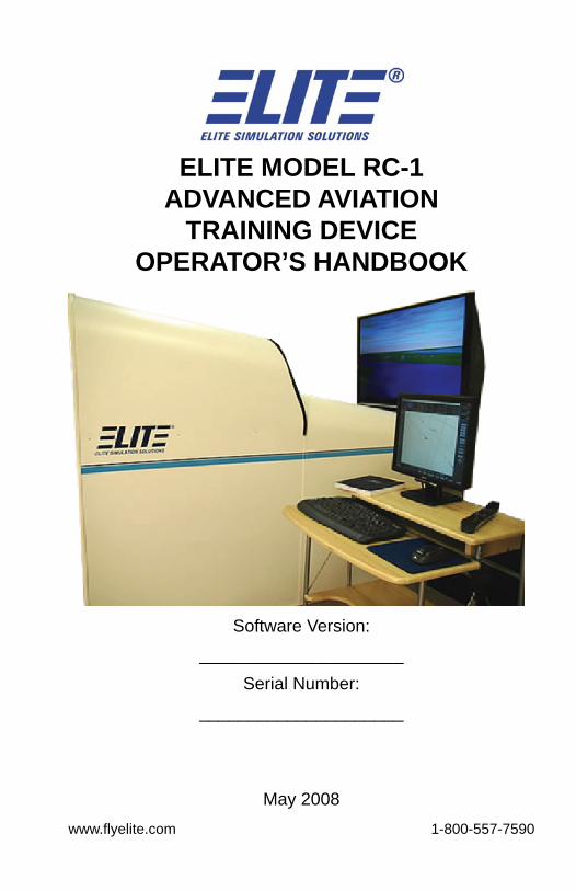
ELITE MODEL RC-1ADVANCED AVIATION
TRAINING DEVICEOPERATOR’S HANDBOOK
Software Version:_____________________
Serial Number:_____________________
May 2008www.fl yelite.com 1-800-557-7590

IntentionallyLeft
Blank
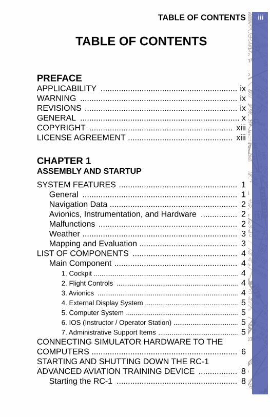
iiiTABLE OF CONTENTS
TABLE OF CONTENTS
PREFACEAPPLICABILITY ............................................................ ixWARNING ..................................................................... ixREVISIONS ................................................................... ixGENERAL ...................................................................... xCOPYRIGHT ............................................................... xiiiLICENSE AGREEMENT .............................................. xiii
CHAPTER 1ASSEMBLY AND STARTUPSYSTEM FEATURES .................................................... 1
General .................................................................... 1Navigation Data ........................................................ 2Avionics, Instrumentation, and Hardware ................ 2Malfunctions ............................................................. 2Weather .................................................................... 3Mapping and Evaluation ........................................... 3
LIST OF COMPONENTS .............................................. 4Main Component ...................................................... 4
1. Cockpit ............................................................................ 42. Flight Controls ................................................................ 43. Avionics .......................................................................... 44. External Display System ................................................. 55. Computer System ........................................................... 56. IOS (Instructor / Operator Station) .................................. 57. Administrative Support Items .......................................... 5
CONNECTING SIMULATOR HARDWARE TO THE COMPUTERS ................................................................ 6STARTING AND SHUTTING DOWN THE RC-1 ADVANCED AVIATION TRAINING DEVICE ................. 8
Starting the RC-1 ..................................................... 8
RC-1 OPERATOR’S MANUALiv
Shutting Down the RC-1 ......................................... 11Initial Confi guration ................................................ 12General Settings .................................................... 13Aircraft Module ....................................................... 14Navigation Databases ............................................ 14
HARDWARE CONFIGURATION ................................. 14Changing System Settings ..................................... 14Flight Controls Calibration ...................................... 15
Limits ................................................................................ 15Null Zone .......................................................................... 16Power Quadrant ............................................................... 16
Changing Throttle Quadrants ................................. 17USB Button ....................................................................... 22
Second Monitor ...................................................... 22INSTRUMENT CONFIGURATION .............................. 23
CHAPTER 2INSTRUCTOR / OPERATOR’S STATION (IOS)MENU DESCRIPTION AND OVERVIEW .................... 25
Program Menu ....................................................... 25Malfunctions Page ............................................................ 27Meteo Page ...................................................................... 28Metar Page ....................................................................... 29Modifi cation Page ............................................................. 30Confi guration Page ........................................................... 31Map Page ......................................................................... 32Control Page ..................................................................... 33Instrument ......................................................................... 34Freeze .............................................................................. 34Quit ................................................................................... 34
PROGRAM FEATURES .............................................. 35Map Page ............................................................... 35
Aircraft Position ................................................................ 37Map Scale ......................................................................... 37Nav Data Symbols ............................................................ 37
vTABLE OF CONTENTS
Map Cursors ..................................................................... 38Map Information ................................................................ 39Map Borders ..................................................................... 39Reposition ......................................................................... 39Multiple ILS/Deselection ................................................... 42Aircraft Snapping .............................................................. 45Map Zoom Levels ............................................................. 46Show Facilities .................................................................. 47Transponder Tag ............................................................... 48MAP Page “Spot Weather” Feature .................................. 49Navigation Databases ...................................................... 50Instrument Approach Scenarios (IAS) .............................. 54State Panel ....................................................................... 57Heading Panel .................................................................. 58Altitude Panel ................................................................... 58Airspeed Panel ................................................................. 59Profi le Button .................................................................... 59Route Button ..................................................................... 70Print Button ....................................................................... 70Heading / Distance Cursor ............................................... 70Route Planner ................................................................... 72Shortcuts .......................................................................... 73Hotplates .......................................................................... 78
Meteo Page ............................................................ 81General Layout (GenView) ............................................... 82Transition Zones ............................................................... 85Wind Direction .................................................................. 86Wind Speed ...................................................................... 86Turbulence ........................................................................ 86Ceiling (Standard View) .................................................... 87Visibility (GenView) ........................................................... 87Clouds (GenView) ............................................................ 89Visibility (Standard View) .................................................. 90Altimeter ........................................................................... 90Temperature ..................................................................... 91Structural Icing .................................................................. 91
RC-1 OPERATOR’S MANUALvi
Saving & Loading Meteo Files .......................................... 94Reference Meteo Time ..................................................... 95
Metar Page ............................................................. 97Active Metar ...................................................................... 97Wind and Gusts ................................................................ 98Using the METAR Page .................................................... 98Using Existing METAR Data ............................................. 98Downloading METAR Files ............................................ 100Station Plot .................................................................... 104Wind Barb Description in the Northern Hemisphere ...... 105Aerodrome Actual Weather METAR AndSPECI Decode .............................................................. 106
Malfunctions Page ................................................ 108Instruments and Systems Failures ................................ 109Failure Time Window ...................................................... 110Immediate Failure ........................................................... 111Specifi c Time Failure ...................................................... 111Receivers, Gear, and Flaps Failures .............................. 112Engine Failures ............................................................... 112Random Failures ............................................................ 114Instrument INOPs ........................................................... 114Failure States ................................................................. 116
Control Page ......................................................... 118Visual Panel .................................................................... 118Preset Level of Detail (GenView) ................................... 119Scenery/Runway Lighting (Standard View) ......................... 120Running the Instrument Approach Scenarios (IAS) ....... 123State Panel .................................................................... 125Time Flown Panel .......................................................... 127
Confi guration Page .............................................. 128State Files ...................................................................... 128
Visual Settings ..................................................... 129Password Protection ............................................ 129Time Difference LT To UTC .................................. 129ATD Detection Report .......................................... 130Activating Failures With Keyboard ....................... 130
viiTABLE OF CONTENTS
Measurement for Weight & Fuel .......................... 131Changing Hanging Color Of Numbers ................. 131Sound and Volume Control .................................. 1323D Sound ............................................................. 132Aircraft Information ............................................... 132Modifi cation Page ................................................. 134
Creating Facilities .......................................................... 134Modifying Facilities ........................................................ 135Deleting Facilities .......................................................... 135Undo Changes ............................................................... 136Facility Info .................................................................... 137
CHAPTER 3EXTERNAL VISUAL DISPLAY - GENVIEW™GENVIEW VISUAL DISPLAY .................................... 143
GenView Vector Data ........................................... 143GenView Runway Defi nitions ............................... 143Taxiing in GenView ............................................... 144Using the Visual Manager Page ........................... 145
CHAPTER 4AIRCRAFT GENERAL DESCRIPTIONGENERAL INSTRUMENTS ...................................... 147
Artifi cial Horizon ................................................... 147Airspeed Indicator ................................................ 147Turn Indicator ....................................................... 148Altimeter ............................................................... 148Vertical Speed Indicator ....................................... 148Gyro Compass ..................................................... 149Horizontal Situation Indicator ............................... 149VOR/LOC/Glideslope Indicator ............................ 150Radio Magnetic Indicator ..................................... 150Moving Dial Indicator ............................................ 151
RADIO NAVIGATION RECEIVERS ........................... 151NAV/COMM .......................................................... 152
RC-1 OPERATOR’S MANUALviii
DME Receiver ...................................................... 153Frequency Mode: ........................................................... 153GS/T Mode: ................................................................... 153RMT Mode: .................................................................... 153
ADF Receiver ....................................................... 154Marker Receiver ................................................... 154Transponder ......................................................... 155GPS Receiver ...................................................... 156
GX55 ............................................................................. 156GX50 ............................................................................. 156GX60 ............................................................................. 156GX65 ............................................................................. 157Trimble 2000 Approach Plus GPS ................................. 157
GPS Annunciator .................................................. 158With Apollo GPS ............................................................ 158With Trimble GPS .......................................................... 159
Using the Course/Heading Panel ......................... 159
INDEX ...................................................................... 163
SUPPLEMENTS ................................................... 171
ixPREFACE
PREFACE
APPLICABILITYApplication of this handbook is limited to the specifi c model of training device and software designated by version number and serial number on the face of the title page of this handbook.
WARNINGAny unauthorized changes to the trainer regarding removal, replacement or repositioning of original fl ight control components, avionics or switches, not in accordance with manufacturer specifi cations, will void the FAA approval for logging fl ight time credit. Only ELITE ATD software may be used with this training device for certifi cation purposes. The instructions and limitations detailed in the FAA letter of approval pertaining to this model of advanced aviation training device must be adhered to and kept in close proximity to the trainer. The controlling authority for the use this training device in a Part 61 or 141 or 142 course of instruction is the Federal Aviation Administration, General Aviation and Commercial Division, 800 Independence Avenue, Washington D.C. 20591.
REVISIONSFor operational purposes, this handbook should be kept in current status with revisions provided with software upgrades or hardware modifi cations. Revisions to this handbook will be distributed whenever necessary as complete replacements or additions and shall be inserted into the handbook as below:
Revision pages will replace only pages a. with the same page number.Insert all additional pages in proper b.
RC-1 OPERATOR’S MANUALx
numerical order within each section.Page numbers followed by a small letter c. shall be inserted in direct sequence with the same common numbered page.
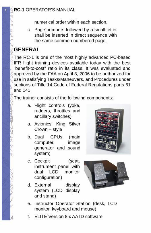
GENERALThe RC-1 is one of the most highly advanced PC-based IFR fl ight training devices available today with the best “benefi t-to-cost” ratio in its class. It was evaluated and approved by the FAA on April 3, 2006 to be authorized for use in satisfying Tasks/Maneuvers, and Procedures under sections of Title 14 Code of Federal Regulations parts 61 and 141.The trainer consists of the following components:
Flight controls (yoke, a. rudders, throttles and ancillary switches)
a. Avionics, King Silver Crown – styleDual CPUs (main b. computer, image generator and sound system)Cockpit (seat, c. instrument panel with dual LCD monitor confi guration)External display d. system (LCD display and stand)Instructor Operator Station (desk, LCD e. monitor, keyboard and mouse)ELITE Version 8.x AATD softwaref.
xiPREFACE
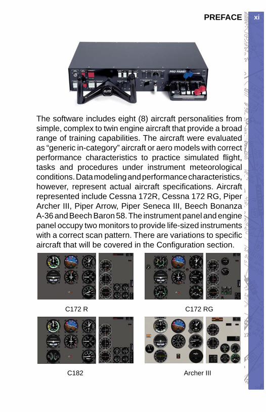
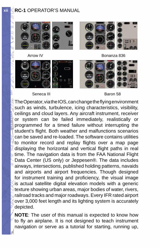
The software includes eight (8) aircraft personalities from simple, complex to twin engine aircraft that provide a broad range of training capabilities. The aircraft were evaluated as “generic in-category” aircraft or aero models with correct performance characteristics to practice simulated fl ight, tasks and procedures under instrument meteorological conditions. Data modeling and performance characteristics, however, represent actual aircraft specifi cations. Aircraft represented include Cessna 172R, Cessna 172 RG, Piper Archer III, Piper Arrow, Piper Seneca III, Beech Bonanza A-36 and Beech Baron 58. The instrument panel and engine panel occupy two monitors to provide life-sized instruments with a correct scan pattern. There are variations to specifi c aircraft that will be covered in the Confi guration section.
C172 R C172 RG
C182 Archer III
RC-1 OPERATOR’S MANUALxii
Arrow IV Bonanza 836
Seneca III Baron 58
The Operator, via the IOS, can change the fl ying environment such as winds, turbulence, icing characteristics, visibility, ceilings and cloud layers. Any aircraft instrument, receiver or system can be failed immediately, realistically or programmed for a timed failure without interrupting the student’s fl ight. Both weather and malfunctions scenarios can be saved and re-loaded. The software contains utilities to monitor record and replay fl ights over a map page displaying the horizontal and vertical fl ight paths in real time. The navigation data is from the FAA National Flight Data Center (US only) or Jeppesen®. The data includes airways, intersections, published holding patterns, navaids and airports and airport frequencies. Though designed for instrument training and profi ciency, the visual image is actual satellite digital elevation models with a generic texture showing urban areas, major bodies of water, rivers, railroad tracks and major roadways. Every IFR rated airport over 3,000 feet length and its lighting system is accurately depicted.NOTE: The user of this manual is expected to know how to fl y an airplane. It is not designed to teach instrument navigation or serve as a tutorial for starting, running up,
xiiiPREFACE
fl ying or shutting down aircraft. It will not describe the purpose or function of aircraft specifi c switches, knobs or levers.
COPYRIGHTCopyright 1989 - 2008 byELITE Simulation SolutionsIm Schorli 18600 Dubendorf, SwitzerlandAll rights reserved.Under the copyright laws, this manual may not be copied, reproduced or distributed in any form or by any means, in whole or in part, without the written consent of the author: ELITE Simulation Solutions AG. Your rights to the software are governed by the accompanying software license agreement.Every effort has been made to ensure that the information in this manual is accurate. ELITE Simulation Solutions AG is not responsible for printing or clerical errors.All terms mentioned in this manual that are actually known to be trademarks or service marks are listed below. ELITE Simulation Solutions AG cannot attest to the accuracy of this information. Use of a term in this manual should not be regarded as affecting the validity of any trademark or service mark.Apple Logo and Macintosh are registered trademarks of Apple Computer. IBM and PC are trademarks of International Business Machines Corporation Windows 95, 98, 2000, Me, NT and XP are trademarks of Microsoft Corporation. Jeppesen is a trademark of Jeppesen Sanderson Inc.
LICENSE AGREEMENTThis is a license agreement and not an agreement for sale. A license agreement is a legal agreement between
RC-1 OPERATOR’S MANUALxiv
you, the end user (You), and ELITE Simulations solutions AG “Licensor.” Please read this software license agreement “Agreement” carefully. If you do not agree with the terms and conditions of this Agreement, you should contact ELITE Simulation Solutions AG within 30 days from the invoice date.Ownership of the Software
The enclosed ELITE software program “Software” and 1. the accompanying written materials are owned by ELITE Simulation Solutions AG , Switzerland, and are protected by United States copyright laws, by laws of other nations, and by international treaties.
Grant Of License
Licensor grants to You the nonexclusive right to use one 2. copy of the Software on the RC-1 in accordance with the terms of the Agreement. You may not install the software on a network or on a computer other than the one that came as a component of the RC-1 Advanced ATD without express written permission from ELITE Simulation Solutions..
Restrictions on Use and Transfer
You may not use the software on another computer or 3. loan, rent, transfer, or assign them to another user except as part of the permanent transfer of the RC-1 aviation training device.
You may not copy the Software, except that you may 4. transfer the Software to a single hard disk for backup or archival purposes. You may not copy the written materials.
You may permanently transfer the RC-1 Software and 5. accompanying written materials (including the most recent update and all prior versions) if you retain no copies and the transferee agrees to be bound by the terms of this Agreement. Such a transfer terminates Your license. You may not rent or lease the Software or otherwise transfer or assign the right to use the Software, except as stated in this paragraph.
You may not reverse engineer, decompile, modify, 6. disassemble or create derivative works based upon the Software in whole or part.
xvPREFACE
Term and Termination
This license terminates if You fail to comply with 7. any provision of this Agreement. You agree upon termination to destroy the Program, with all copies, modifi cations and merged portions in any form, including any copy in Your computer memory or on a hard disk .
Limited Warranty
Licensor warrants that the Software will perform 8. substantially in accordance with the accompanying written materials for a period of 90 days from the date of your receipt of the Software. Any implied warranties on the Software are limited to 90 days. Some states do not allow limitations on duration of an implied warranty, so the above limitation may not apply to You.
LICENSOR DISCLAIMS ALL OTHER WARRANTIES, 9. EITHER EXPRESS OR IMPLIED, INCLUDING BUT NOT LIMITED TO IMPLIED WARRANTIES OF MERCHANTA BILITY, FITNESS FOR A PARTICULAR PURPOSE, AND NON-INFRINGEMENT, WITH RESPECT TO THE SOFTWARE AND THE ACCOMPANYING MATERIALS. This limited warranty gives You specifi c legal rights. You may have others, which vary from state to state.
LICENSOR’S ENTIRE LIABILITY AND YOUR 10. EXCLUSIVE REMEDY SHALL BE, AT LICENSOR’S CHOICE, EITHER (A) RETURN OF THE PRICE PAID OR (B) REPLACEMENT OF THE SOFTWARE THAT DOES NOT MEET LICENSOR’S LIMITED WARRANTY AND WHICH IS RETURNED TO LICENSOR WITH A COPY OF YOUR RECEIPT. Any replacement Software will be warranted for the remainder of the original warranty period or 30 days, whichever is longer. These remedies are not available outside the United States of America.
This Limited Warranty is void if failure of the Software 11. has resulted from modifi cation, accident, abuse, or misapplication.
IN NO EVENT WILL LICENSOR BE LIABLE TO 12.
RC-1 OPERATOR’S MANUALxvi
YOU FOR DAMAGES, INCLUDING ANY LOSS OF PROFITS, LOST SAVINGS, OR OTHER INCIDENTAL OR CONSEQUENTIAL DAMAGES ARISING OUT OF YOUR USE OR INABILITY TO USE THE SOFTWARE. Because some states do not allow the exclusion or limitation of liability for consequential or incidental damages, the above limitation may not apply to You.
This Agreement constitutes the entire agreement 13. between You and Licensor regarding the Software and supersedes any other information, advice or representation given to You by Licensor or its dealers, distributors agents or employees. This Agreement is governed by the laws of the State of Florida, U.S.A. and Switzerland, whichever is applicable. If any provision of this Agreement is found to be invalid by any court of competent jurisdiction, the balance of this Agreement shall remain in full force and effect.
If You have any questions concerning this Agreement 14. or wish to contact Licensors for any reason, please write to:
ELITE Simulation Solutions AGIm Schorli 18600 Dubendorf, Switzerland
U.S. Government Restricted Rights. The Software and 15. documentation are provided with Restricted Rights. Use, duplication, or disclosure by the Government is subject to restrictions set forth in subparagraph (c)(1) of The Rights in Technical Data and Computer Software clause at DFARS 252.227-7013 or subparagraphs (c)(1)(ii) and (2) of Commercial Computer Software - Restricted Rights at 48 CFR 52.227-19, as applicable.
1CHAPTER 1: Assembly and Startup
CHAPTER 1 ASSEMBLY AND STARTUP
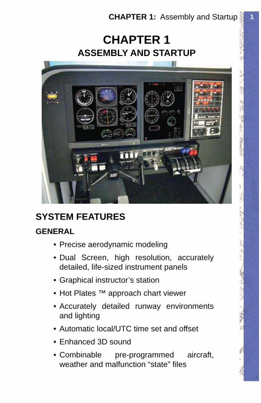
SYSTEM FEATURESGENERAL
Precise aerodynamic modeling• Dual Screen, high resolution, accurately • detailed, life-sized instrument panelsGraphical instructor’s station• Hot Plates ™ approach chart viewer• Accurately detailed runway environments • and lightingAutomatic local/UTC time set and offset• Enhanced 3D sound• Combinable pre-programmed aircraft, • weather and malfunction “state” fi les
RC-1 OPERATOR’S MANUAL2
NAVIGATION DATAUS and Canadian navigational databases• US • GenView ™ Visual DatabaseInternational GPS database• Add, delete, and modify navigation facilities/• database elements
AVIONICS, INSTRUMENTATION, AND HARDWARE• Bendix King Silver Crown Avionics• Trimble 2000 Approach Plus™ GPS• Apollo Series GPS
Selectable HSI/RMI and DG/ADF• Moving map display•
• Autopilot / fl ight directorAltitude/vertical speed preselect•
• Radar altimeter• Electric pitch trim• Rudder trim
Toe brakes w/proportional braking•
MALFUNCTIONSFully programmable instrument, power plant, • avionics, gear, fl ap and system failuresSet immediate, timed, gradual, and random • failuresAccurately modeled insidious failure • behaviorVirtual instrument covers (for partial panel • work)Create and save an unlimited number of •
3CHAPTER 1: Assembly and Startup
malfunction “state” fi les.
WEATHERAdvanced static and/or dynamic weather • modelingFully programmable wind, turbulence, • visibility, clouds, temperature, pressure and icingDownloadable METAR reports and integrated • real time weatherCreate and save an unlimited number of • weather “state” fi les
MAPPING AND EVALUATIONPlan, profi le and extended profi le views• Gear/fl ap position graph and airspeed plot•
• Flight Data Recorder with VCR-style playback controlVirtual airport facility directory• Transponder tag w/squawk code, heading • and altitude readout“• Spot WX” station model display symbology (wind, temp, visibility and pressure display)Quick “click and drag” aircraft repositioning• Real time and/or recorded fl ight instrument • presentation on IOS Map ScreenRoute planner• Heading/Distance MAP cursor (instant E6B-• style calculations)Instrument Approach Scenarios (optional)• Print, save, and replay and unlimited number •
RC-1 OPERATOR’S MANUAL4
of aircraft “path” fi lesCreate and save an unlimited number of • aircraft “state” fi les
LIST OF COMPONENTSPlease insure that you have all RC-1 components before assembly:
MAIN COMPONENT
1. COCKPITRAC (• Ready to Assemble Cockpit) with assembly instructionsFloor mounting hardware for pedals• Floor mounting hardware for seat•
• ChronometerSeat• Seat base• Seat base nuts•
2. FLIGHT CONTROLSELITE PPII Flight Console (includes USB • cable, master power key and 9v Power Supply (300 to 500 mA))ELITE Rudder Pedals with USB cable (10 • ft)SEL (• Single Engine Land) Throttle Quadrant
3. AVIONICS• AP3000 Avionics Panel (includes USB cable
and 9v Power Supply (1.2 Amp))AP3 Quick Start Guide•
5CHAPTER 1: Assembly and Startup
4. EXTERNAL DISPLAY SYSTEMLCD TV with high density video cable (may • be PC, HDMI or AVI)LCD TV Stand w/ assembly instructions•
5. COMPUTER SYSTEMComputer rack with power strip• Main computer (with pre-loaded ELITE ATD • software and USB WIBU key)Visual computer (with pre-loaded ELITE • visual data) keyboard mouse speakers IG installation instructions 7 port USB hub
6. IOS ( INSTRUCTOR / OPERATOR STATION)17” LCD Instructor Monitor and high density • monitor extension cableInstructor Desk•
7. ADMINISTRATIVE SUPPORT ITEMSSoftware (Windows CD, ELITE ATD DVD, • ELITE External Visual DVD)RC-1 Letter & Qualifi cation Guide• RC-1 Operator’s Handbook•
NOTE: All software is pre-installed and ready to run. Software CDs and DVDs are for archival purposes only! Do not install software until you contact ELITE Technical Support (407-359-8488)RC-1 main components may ship from different locations. Items 2, 3, 5, 6 and 7 plus the seat, seat base and hardware
RC-1 OPERATOR’S MANUAL6
usually ship from ELITE SIMULATION SOLUTIONS, Oviedo, Florida. Items 1 and 4 will be drop shipped direct from the manufacturer. ELITE Customer Service will arrange and track all shipped components. Please contact them for questions, missing parts and/or assistance.
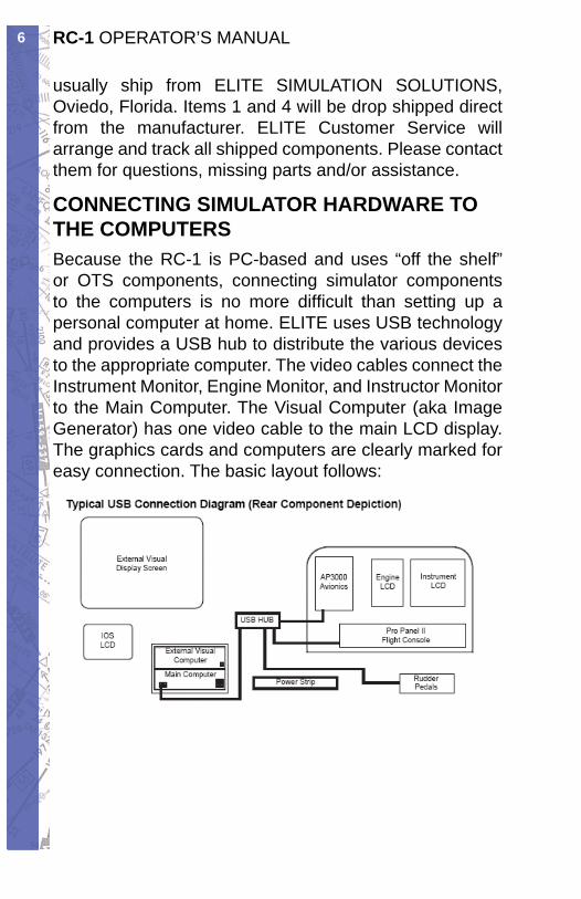
CONNECTING SIMULATOR HARDWARE TO THE COMPUTERSBecause the RC-1 is PC-based and uses “off the shelf” or OTS components, connecting simulator components to the computers is no more diffi cult than setting up a personal computer at home. ELITE uses USB technology and provides a USB hub to distribute the various devices to the appropriate computer. The video cables connect the Instrument Monitor, Engine Monitor, and Instructor Monitor to the Main Computer. The Visual Computer (aka Image Generator) has one video cable to the main LCD display. The graphics cards and computers are clearly marked for easy connection. The basic layout follows:
7CHAPTER 1: Assembly and Startup
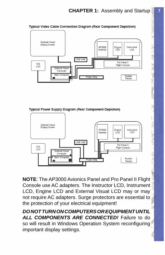
NOTE: The AP3000 Avionics Panel and Pro Panel II Flight Console use AC adapters. The Instructor LCD, Instrument LCD, Engine LCD and External Visual LCD may or may not require AC adapters. Surge protectors are essential to the protection of your electrical equipment!DO NOT TURN ON COMPUTERS OR EQUIPMENT UNTIL ALL COMPONENTS ARE CONNECTED! Failure to do so will result in Windows Operation System reconfi guring important display settings.
RC-1 OPERATOR’S MANUAL8
STARTING AND SHUTTING DOWN THE RC-1 ADVANCED AVIATION TRAINING DEVICESTARTING THE RC-1
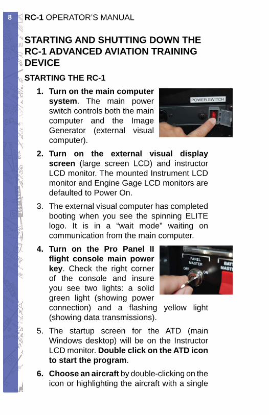
Turn on the main computer 1. system. The main power switch controls both the main computer and the Image Generator (external visual computer).Turn on the external visual display 2. screen (large screen LCD) and instructor LCD monitor. The mounted Instrument LCD monitor and Engine Gage LCD monitors are defaulted to Power On.The external visual computer has completed 3. booting when you see the spinning ELITE logo. It is in a “wait mode” waiting on communication from the main computer.Turn on the 4. Pro Panel II fl ight console main power key. Check the right corner of the console and insure you see two lights: a solid green light (showing power connection) and a fl ashing yellow light (showing data transmissions).The startup screen for the 5. ATD (main Windows desktop) will be on the Instructor LCD monitor. Double click on the ATD icon to start the program.Choose an aircraft6. by double-clicking on the icon or highlighting the aircraft with a single
9CHAPTER 1: Assembly and Startup
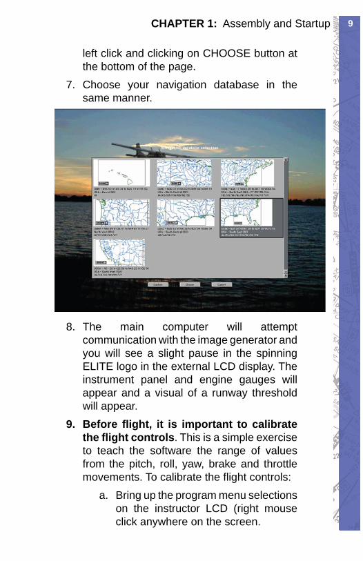
left click and clicking on CHOOSE button at the bottom of the page.Choose your navigation database in the 7. same manner.
The main computer will attempt 8. communication with the image generator and you will see a slight pause in the spinning ELITE logo in the external LCD display. The instrument panel and engine gauges will appear and a visual of a runway threshold will appear.Before fl ight, it is important to calibrate 9. the fl ight controls. This is a simple exercise to teach the software the range of values from the pitch, roll, yaw, brake and throttle movements. To calibrate the fl ight controls:
Bring up the program menu selections a. on the instructor LCD (right mouse click anywhere on the screen.
RC-1 OPERATOR’S MANUAL10
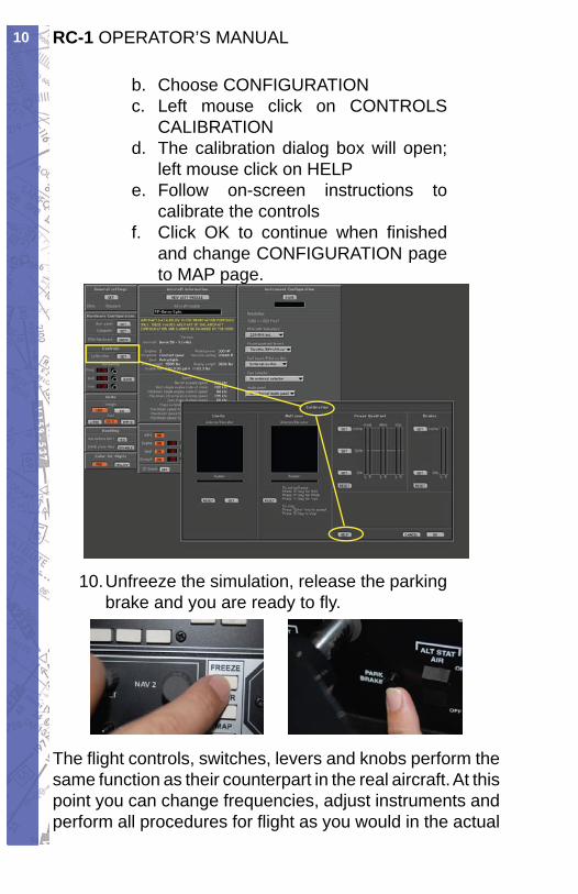
Choose b. CONFIGURATIONLeft mouse click on c. CONTROLS CALIBRATIONThe calibration dialog box will open; d. left mouse click on HELPFollow on-screen instructions to e. calibrate the controlsClick OK to continue when fi nished f. and change CONFIGURATION page to MAP page.
Unfreeze the simulation, release the parking 10. brake and you are ready to fl y.
The fl ight controls, switches, levers and knobs perform the same function as their counterpart in the real aircraft. At this point you can change frequencies, adjust instruments and perform all procedures for fl ight as you would in the actual
11CHAPTER 1: Assembly and Startup
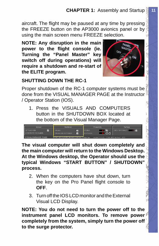
aircraft. The fl ight may be paused at any time by pressing the FREEZE button on the AP3000 avionics panel or by using the main screen menu FREEZE selection.NOTE: Any disruption in the main power to the fl ight console (ie. Turning the “Panel Master” key switch off during operations) will require a shutdown and re-start of the ELITE program.
SHUTTING DOWN THE RC-1Proper shutdown of the RC-1 computer systems must be done from the VISUAL MANAGER PAGE at the Instructor / Operator Station (IOS).
Press the 1. VISUALS AND COMPUTERS button in the SHUTDOWN BOX located at the bottom of the Visual Manager Page.
The visual computer will shut down completely and the main computer will return to the Windows Desktop. At the Windows desktop, the Operator should use the typical Windows “START BUTTON” / SHUTDOWN” process.
When the computers have shut down, turn 2. the key on the Pro Panel fl ight console to OFF.Turn off the IOS LCD monitor and the External 3. Visual LCD Display.
NOTE: You do not need to turn the power off to the instrument panel LCD monitors. To remove power completely from the system, simply turn the power off to the surge protector.
RC-1 OPERATOR’S MANUAL12
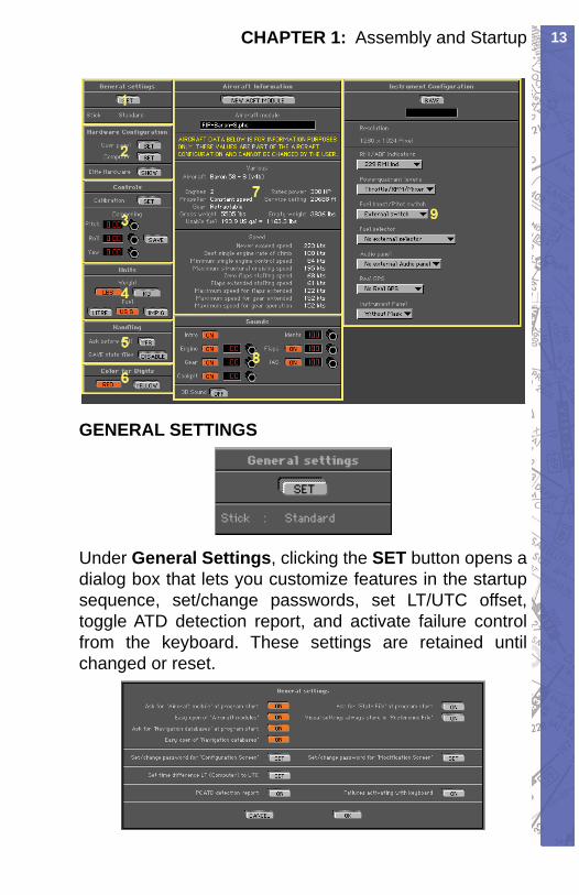
INITIAL CONFIGURATIONIt is recommended that this page be reviewed carefully. After confi guring to your satisfaction, press the SAVE button to keep all values. These selections are stored in a PREF folder in the program directory. These values will be read when starting the program. Once set, you will seldom need to go to this page. The instructor or operator can set a password to prevent access to the Confi guration Page.Certain features of each aircraft can be changed or confi gured to personal preference or training requirement. An example of Confi guration was the control calibration performed in item 9 above. Some settings are general and apply to all aircraft being fl own and some settings (instrument confi guration) are specifi c to the aircraft selected to be fl own.You get to the CONFIGURATION PAGE by right mouse clicking on the instructor’s monitor when ELITE is running. This brings up the ELITE Main Menu. Click on CONFIGURATION PAGE or use the keyboard shortcut “alt G”.The Confi guration Page consists of nine sections: General Settings (1), Hardware Confi guration (2), Controls (3), Units (4), Handling (5), Color for Digits (6), Aircraft Information (7), Sounds (8) and Instrument (9). This section will cover the basics to get the RC-1 up and running. Other information from this screen will be covered in Chapter Two.
13CHAPTER 1: Assembly and Startup
GENERAL SETTINGS
Under General Settings, click ing the SET button opens a di a log box that lets you cus tom ize features in the startup sequence, set/change pass words, set LT/UTC offset, toggle ATD detection report, and activate fail ure control from the keyboard. These settings are re tained un til changed or reset.
RC-1 OPERATOR’S MANUAL14
AIRCRAFT MODULEWhen “Ask for Aircraft Mod ule at program start” but ton is ON (orange), ELITE will ask you (on every startup) to select an aircraft module. “Easy open of air craft modules” allows you to choose an aircraft by view ing thumbnails (small pictorial representations) of each aircraft cockpit. This is the de fault and recommended setting. The same is true for NAV databases.
NAVIGATION DATABASESWhen “Ask for Navigation Databases at program start” but ton is ON, ELITE will ask (on every startup) to se lect a NAV database area to fl y in. “Easy open of Nav i ga tion databases” al lows you to choose a NAV area by viewing thumbnail maps of all available individual nav i ga tion areas installed.NOTE: To have ELITE automatically start up (de fault) to the same aircraft and NAV area each time, fi rst make sure you are currently using the desired aircraft and NAV area you would like for subsequent startups, then turn OFF both “Ask for Air craft mod ule” and “Ask for Nav i ga tion da ta bas es at program start” but tons.
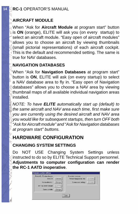
HARDWARE CONFIGURATIONCHANGING SYSTEM SETTINGSDo NOT USE Changing System Settings unless instructed to do so by ELITE Technical Support personnel. Adjustments to computer confi guration can render the RC-1 AATD inoperative.
15CHAPTER 1: Assembly and Startup
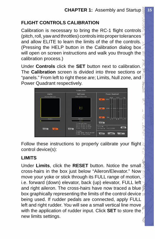
FLIGHT CONTROLS CALIBRATIONCal i bra tion is necessary to bring the RC-1 fl ight controls (pitch, roll, yaw and throttles) con trols into proper tolerances and allow ELITE to learn the limits of the of the controls. (Pressing the HELP button in the Calibration dialog box will open on screen instructions and walk you through the calibration process.)Under Controls click the SET button next to cal i bra tion. The Calibration screen is di vid ed into three sec tions or “panels.” From left to right these are; Lim its, Null zone, and Power Quadrant re spec tive ly.
Follow these instructions to properly cal i brate your fl ight con trol device(s):
LIMITSUnder Limits, click the RESET but ton. No tice the small cross-hairs in the box just be low “Ai le ron/El e va tor.” Now move your yoke or stick through its FULL range of motion, i.e. for ward (down) el e va tor, back (up) elevator, FULL left and right ai le ron. The cross-hairs have now traced a blue box graph i cal ly rep re sent ing the lim its of the con trol device be ing used. If rudder pedals are connected, apply FULL left and right rud der. You will see a small ver ti cal line move with the application of rudder input. Click SET to store the new limits settings.
RC-1 OPERATOR’S MANUAL16
NULL ZONEThe center Null Zone panel allows the user to defi ne a “box” within which the control device(s) is considered centered. If a fl ight control does not phys i cal ly return exactly to center but is still with in the lim its of the “box” defi ned under the Null Zone panel, no fl ight com mand in put will be sent to the soft ware. Some experimentation with different Null zone set tings may be necessary to achieve optimum control re sponse. In general, larger Null zones require greater fl ight con trol travel accompanied by a coincident perceived de crease in sensitivity. Under Null Zone, click RESET. Press the “R” key on your key board and move the stick or yoke to adjust the size of the aileron (Roll) Null zone. To ac cept and store this setting hit ENTER or press the “S” key to return to the previously stored val ue. Next, press the “P” key on your keyboard and move the stick or yoke to adjust the size of the elevator (Pitch) Null zone. To accept this setting hit ENTER or press the “S” key to return to the pre vi ous ly stored val ue. If rud der ped als are con nect ed press the “Y” key on the key board and move the pedals to adjust the width of the of the rudder (Yaw) Null zone. NOTE: Clicking the RESET but ton returns ALL Null zone settings to default. In di vid u al Null zones can be adjusted without clicking RESET by sim ply press ing “R”, “P”, or “Y” keys respectively.
POWER QUADRANTUnder Power Quadrant, click RE SET. Now phys i cal ly move the Mix ture, Prop, and Throt tle le vers (if applicable) on your power quad rant or sim i lar device to their halfway position.*Do NOT use lines on screen under PWR, RPM, and MIX columns for reference. Once levers are po si tioned phys i cal ly at 50% (on device) click the middle SET button
17CHAPTER 1: Assembly and Startup
next to the 50% marking on screen. Next, move the levers FULL forward (Throttle OPEN, Prop HIGH, Mixture RICH) and click the top 100% SET button. Finally, move the levers FULL aft and click the bottom 0% SET button.*NOTE: If a King Air quadrant or other turbine quadrant is being used then it will be necessary to move the levers to their respective detent positions (Idle, Feather, Low Idle) rather than the halfway position. Calibration is now complete! Click OK to save these settings & return to the Con fi g u ra tion page, or CAN CELto return and revert to previous settings with out saving. Quit and re start ELITE for new cal i bra tion set tings to take affect.Real air craft are in her ent ly sta ble, sim u la tors are not. For in ex pe ri enced sim u la tor pi lots, the most com mon dif fi cul ty is over-con trol ling or getting used to the con trol sen si tiv i ty. Prac tice ba sic fl y ing ma neu vers as you would in any new air craft tran si tion be fore starting your IFR practice. Re mem ber “the less is more” adage and make small pitch and roll corrections for variation in altitude and/or heading. Do NOT chase the VSI. Monitor in stru ment/nee dle trend, not just move ment. This makes for smooth, precise, in stru ment fl ight and prevents awk ward action/reaction responses.
CHANGING THROTTLE QUADRANTSThe ELITE® RC-1 comes with both a single engine “Piper Style” throttle quadrant and a multi-engine throttle quadrant. A Cessna-style vernier two or three element throttle quadrant is available as an option.To change the throttle quadrant from the RC-1 follow these simple steps:
RC-1 OPERATOR’S MANUAL18
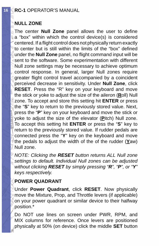
Turn off the Master Panel Power switch using 1. the key switch.
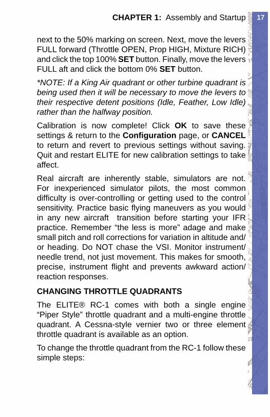
Remove the left and right thumbscrews by 2. turning counterclockwise, supporting the throttle quadrant with a free hand.
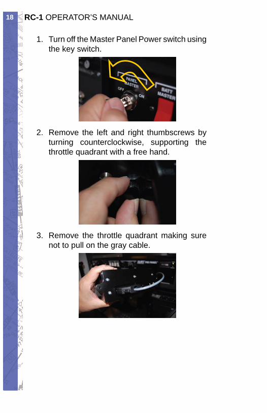
Remove the throttle quadrant making sure 3. not to pull on the gray cable.
19CHAPTER 1: Assembly and Startup
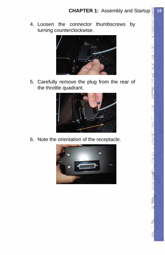
Loosen the connector thumbscrews by 4. turning counterclockwise.
Carefully remove the plug from the rear of 5. the throttle quadrant.
Note the orientation of the receptacle.6.
RC-1 OPERATOR’S MANUAL20
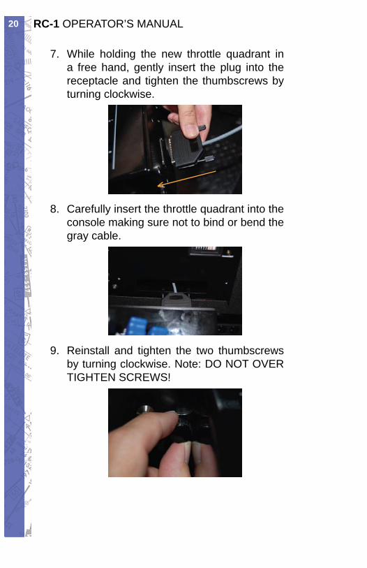
While holding the new throttle quadrant in 7. a free hand, gently insert the plug into the receptacle and tighten the thumbscrews by turning clockwise.
Carefully insert the throttle quadrant into the 8. console making sure not to bind or bend the gray cable.
Reinstall and tighten the two thumbscrews 9. by turning clockwise. Note: DO NOT OVER TIGHTEN SCREWS!
21CHAPTER 1: Assembly and Startup
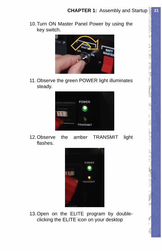
Turn ON 10. Master Panel Power by using the key switch.
Observe the green 11. POWER light illuminates steady.
Observe the amber 12. TRANSMIT light fl ashes.
Open on the ELITE program by double-13. clicking the ELITE icon on your desktop
RC-1 OPERATOR’S MANUAL22
USB BUTTON
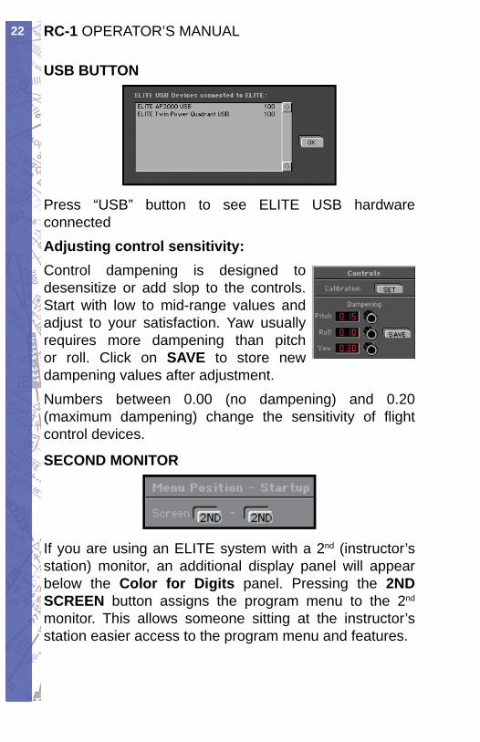
Press “USB” button to see ELITE USB hardware connectedAdjusting control sensitivity:Control dampening is de signed to de sen si tize or add slop to the controls. Start with low to mid-range values and adjust to your sat is fac tion. Yaw usu al ly requires more dampening than pitch or roll. Click on SAVE to store new dampening values after ad just ment.Numbers between 0.00 (no dampening) and 0.20 (max i mum dampening) change the sensitivity of fl ight con trol devices.
SECOND MON I TOR
If you are using an ELITE system with a 2nd (in struc tor’s sta tion) monitor, an ad di tion al dis play panel will appear be low the Color for Digits pan el. Pressing the 2ND SCREEN button assigns the program menu to the 2nd
monitor. This allows someone sitting at the in struc tor’s station easier access to the pro gram menu and features.
23CHAPTER 1: Assembly and Startup
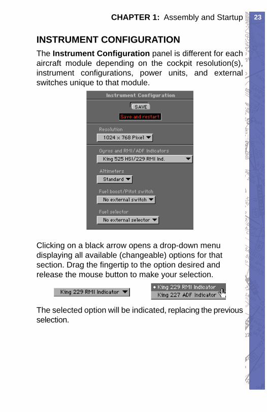
INSTRUMENT CONFIGURATIONThe Instrument Con fi g u ra tion panel is different for each aircraft module de pend ing on the cockpit resolution(s), instrument con fi g u ra tions, power units, and external switches unique to that mod ule.
Clicking on a black arrow opens a drop-down menu displaying all available (changeable) options for that section. Drag the fi n ger tip to the option desired and re lease the mouse button to make your selection.
The selected option will be indicated, re plac ing the pre vi ous selection.

RC-1 OPERATOR’S MANUAL24
IntentionallyLeft
Blank
25CHAPTER 2: Instructor / Operator’s Station (IOS)
CHAPTER 2 INSTRUCTOR / OPERATOR’S STATION (IOS)
MENU DESCRIPTION AND OVERVIEWWhen the instruments are displayed in the cockpit and the external visual displays shows a runway, the IOS LCD monitor will depict a map screen. From here, the operator can access all areas of the program through a MENU system. A brief over view of the MENU items follow:
PROGRAM MENUAfter starting the program, you will enter the simulation in the cockpit (in front of the Instrument panel).The MENU button at the bottom right of your instructor screen is your access to the many features.
Click and hold on the MENU button to open the menu. While holding your mouse button, move the cursor to the menu selection and release. As you move through each selection, the item to be opened will be highlighted. Keyboard shortcuts are listed be side their corresponding menu item. For shortcuts, hold the key board ALT key and the designated letter. CAPS Lock should be OFF.NOTE: The simulation is in the FREEZE mode if Menu or FREEZE is colored red.
RC-1 OPERATOR’S MANUAL26
Exits Program
Visual Manager Page
Malfunctions Page
Active METAR
Weather Page
Nav Data Modifi cation
Confi guration Page
Map Page
Control Page
Instrument Panel
Helps Tips
Simulation Freeze/Unfreeze
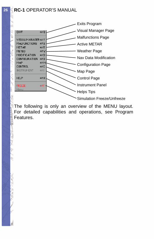
The following is only an overview of the MENU layout. For detailed capabilities and operations, see Program Features.
27CHAPTER 2: Instructor / Operator’s Station (IOS)
MALFUNCTIONS PAGE
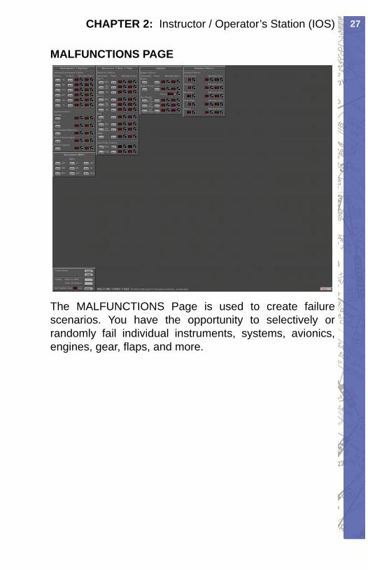
The MALFUNCTIONS Page is used to create failure scenarios. You have the opportunity to selectively or randomly fail individual instruments, systems, avionics, engines, gear, fl aps, and more.
RC-1 OPERATOR’S MANUAL28
METEO PAGE
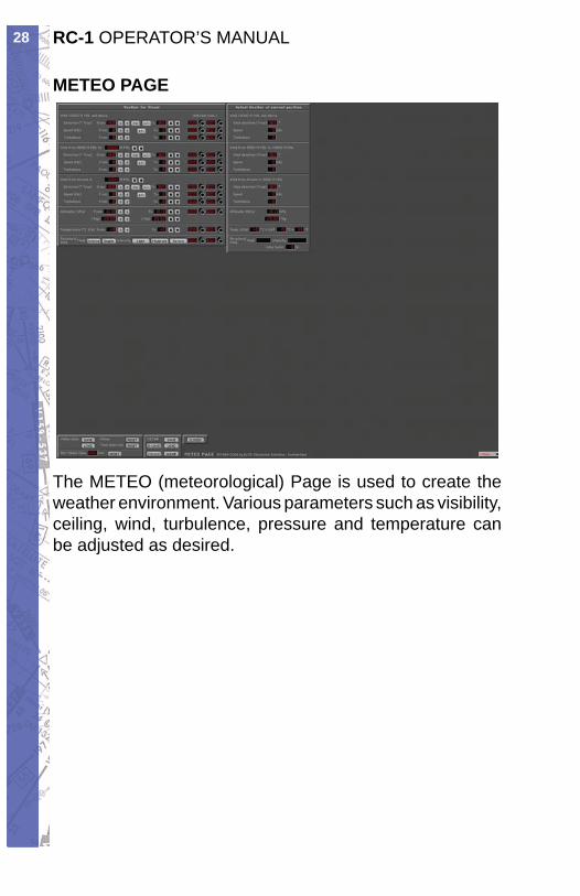
The METEO (meteorological) Page is used to create the weather environment. Various parameters such as visibility, ceiling, wind, turbulence, pressure and temperature can be adjusted as desired.
29CHAPTER 2: Instructor / Operator’s Station (IOS)
METAR PAGE
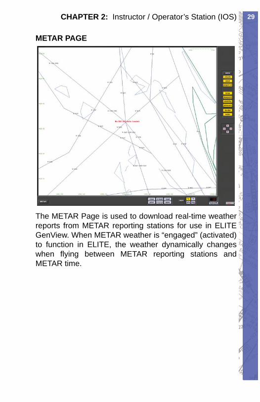
The METAR Page is used to download real-time weather reports from METAR reporting stations for use in ELITE GenView. When METAR weather is “engaged” (activated) to function in ELITE, the weather dynamically changes when fl ying between METAR reporting stations and METAR time.
RC-1 OPERATOR’S MANUAL30
MODIFICATION PAGE
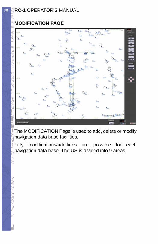
The MODIFICATION Page is used to add, delete or modify navigation data base facilities.Fifty modifi cations/additions are possible for each navigation data base. The US is divided into 9 areas.
31CHAPTER 2: Instructor / Operator’s Station (IOS)
CONFIGURATION PAGE
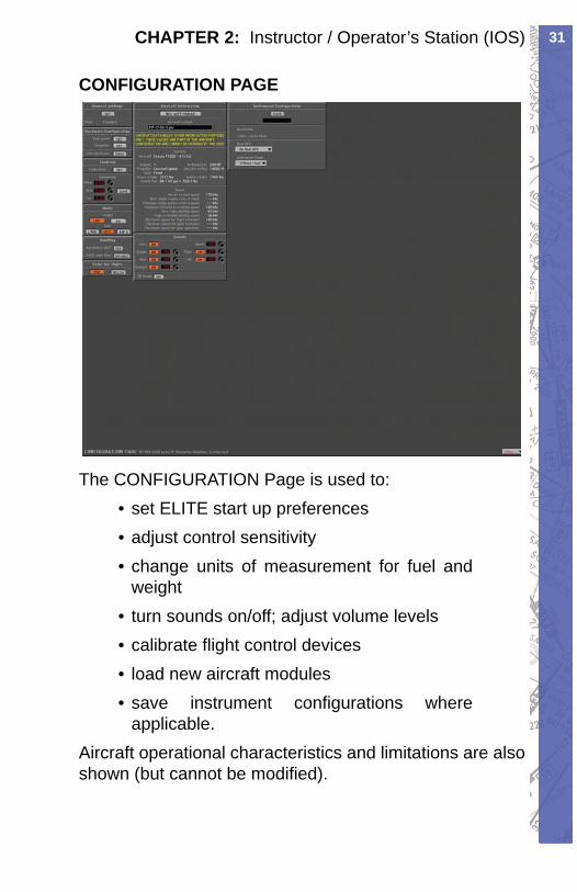
The CONFIGURATION Page is used to:set ELITE start up preferences• adjust control sensitivity• change units of measurement for fuel and • weightturn sounds on/off; adjust volume levels• calibrate fl ight control devices• load new aircraft modules• save instrument confi gurations where • applicable.
Aircraft operational characteristics and limitations are also shown (but cannot be modifi ed).
RC-1 OPERATOR’S MANUAL32
MAP PAGE
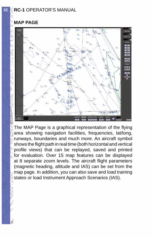
The MAP Page is a graphical representation of the fl ying area showing navigation facilities, frequencies, lat/long, runways, boundaries and much more. An aircraft symbol shows the fl ight path in real time (both horizontal and vertical profi le views) that can be replayed, saved and printed for evaluation. Over 15 map features can be displayed at 8 separate zoom levels. The aircraft fl ight parameters (magnetic heading, altitude and IAS) can be set from the map page. In addition, you can also save and load training states or load Instrument Approach Scenarios (IAS).
33CHAPTER 2: Instructor / Operator’s Station (IOS)
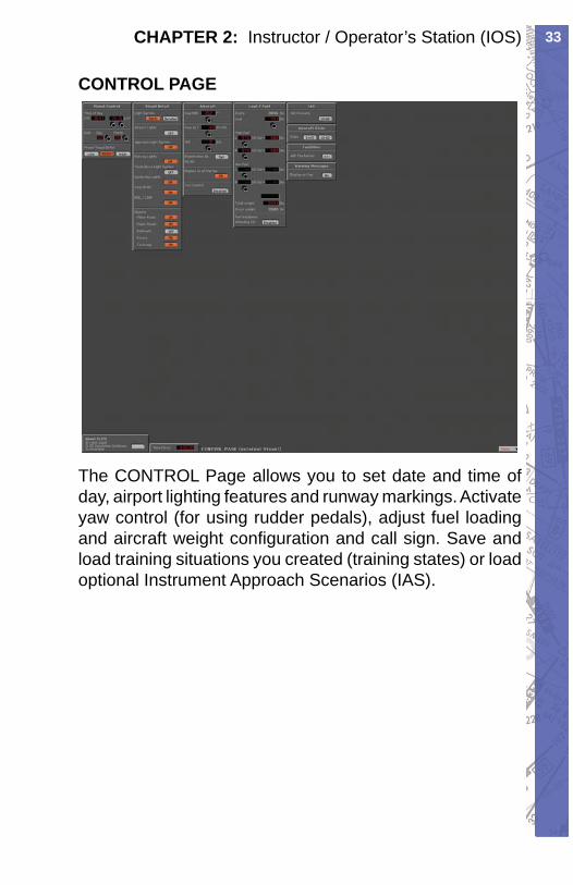
CONTROL PAGE
The CONTROL Page allows you to set date and time of day, airport lighting features and runway markings. Activate yaw control (for using rudder pedals), adjust fuel loading and aircraft weight confi guration and call sign. Save and load training situations you created (training states) or load optional Instrument Approach Scenarios (IAS).
RC-1 OPERATOR’S MANUAL34
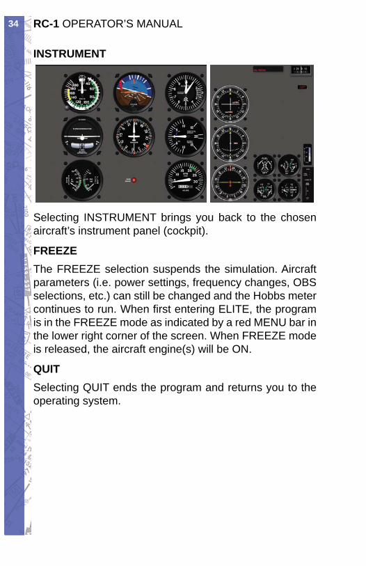
INSTRUMENT
Selecting INSTRUMENT brings you back to the chosen aircraft’s instrument panel (cockpit).
FREEZEThe FREEZE selection suspends the simulation. Aircraft parameters (i.e. power settings, frequency changes, OBS selections, etc.) can still be changed and the Hobbs meter continues to run. When fi rst entering ELITE, the program is in the FREEZE mode as indicated by a red MENU bar in the lower right corner of the screen. When FREEZE mode is released, the aircraft engine(s) will be ON.
QUITSelecting QUIT ends the program and returns you to the operating system.
35CHAPTER 2: Instructor / Operator’s Station (IOS)
PROGRAM FEATURESMAP PAGE
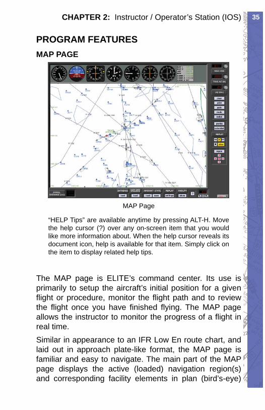
MAP Page
“HELP Tips” are available anytime by pressing ALT-H. Move the help cursor (?) over any on-screen item that you would like more information about. When the help cursor reveals its document icon, help is available for that item. Simply click on the item to dis play re lat ed help tips.
The MAP page is ELITE’s command center. Its use is primarily to setup the aircraft’s initial position for a given fl ight or procedure, monitor the fl ight path and to review the fl ight once you have fi nished fl ying. The MAP page allows the instructor to monitor the progress of a fl ight in real time.Similar in appearance to an IFR Low En route chart, and laid out in approach plate-like format, the MAP page is familiar and easy to navigate. The main part of the MAP page displays the active (loaded) navigation region(s) and corresponding facility elements in plan (bird’s-eye)
RC-1 OPERATOR’S MANUAL36
view. Airports, runways, VORs, NDBs, airways, fi xes, markers, DMEs, localizers, glideslopes, Flight Information Region (FIR) boundaries, country borders, comments and communication frequencies are all graphically and/or textually represented. Pressing the Profi le button brings up a profi le view (similar to the profi le view on an approach plate). Other knobs, buttons, and data windows located around the pe riph ery of the main map display are used to control the following items, discussed in detail later in this sec tion.
Aircraft HEADING• Aircraft ALTITUDE• Aircraft AIRSPEED• Flight path CLEAR• MAP Page PRINT• Flight PATH save/load• ROUTE save/load• RADIAL (compass rose) display• PROFILE view display• Flight path REPLAY• Aircraft REPOSition• DATABASE (Nav region) load• IAS (Instrument Approach Scenario) load• AIRCRAFT STATE save/load• REPLAY settings• FACILITY display• ZOOM•
37CHAPTER 2: Instructor / Operator’s Station (IOS)
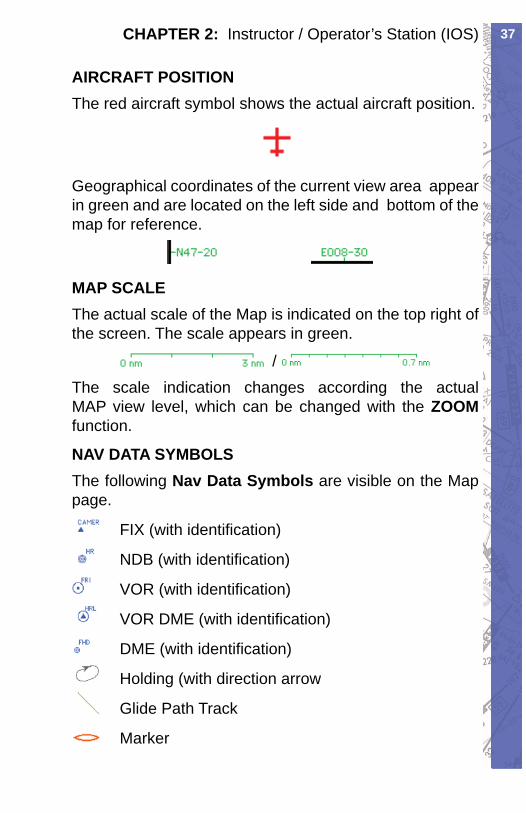
AIRCRAFT POSITIONThe red air craft symbol shows the ac tu al aircraft position.
Geographical coordinates of the current view area appear in green and are located on the left side and bot tom of the map for reference.
MAP SCALEThe actual scale of the Map is indicated on the top right of the screen. The scale appears in green.
/ The scale indication changes according the ac tu al MAP view level, which can be changed with the ZOOM func tion.
NAV DATA SYMBOLSThe following Nav Data Symbols are visible on the Map page.
FIX (with iden ti fi ca tion)
NDB (with iden ti fi ca tion)
VOR (with identifi cation)
VOR DME (with identifi cation)
DME (with identifi cation)
Holding (with direction arrow
Glide Path Track
Marker
RC-1 OPERATOR’S MANUAL38
Localizer (yellow) transmitter
Glideslope (red) transmitter
Runway with displaced threshold
Airport Symbol
Communication frequencies
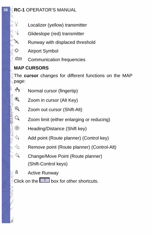
MAP CURSORSThe cursor changes for different functions on the MAP page:
Normal cursor (fi ngertip)
Zoom in cursor (Alt Key)
Zoom out cursor (Shift-Alt)
Zoom limit (either enlarging or reducing)
Heading/Distance (Shift key)
Add point (Route planner) (Control key)
Remove point (Route planner) (Control-Alt)
Change/Move Point (Route planner) (Shift-Control keys)
Active Runway
Click on the box for other shortcuts.
39CHAPTER 2: Instructor / Operator’s Station (IOS)
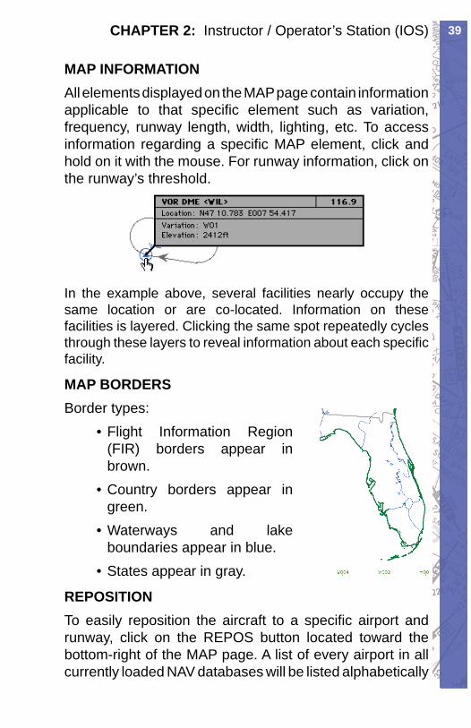
MAP INFORMATIONAll elements displayed on the MAP page contain information applicable to that specifi c element such as variation, frequency, runway length, width, light ing, etc. To access in for ma tion re gard ing a specifi c MAP el e ment, click and hold on it with the mouse. For runway in for ma tion, click on the runway’s threshold.
In the example above, several facilities nearly oc cu py the same location or are co-located. In for ma tion on these facilities is layered. Clicking the same spot re peat ed ly cycles through these layers to reveal in for ma tion about each specifi c facility.
MAP BORDERSBorder types:
• Flight Information Region (FIR) borders ap pear in brown.Country borders ap pear in • green.Waterways and lake • bound aries appear in blue.States appear in gray.•
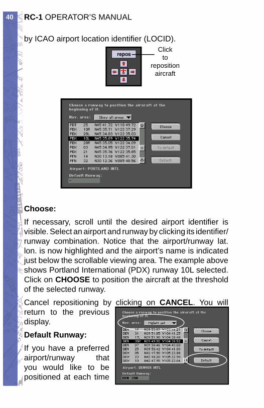
REPOSITIONTo eas i ly re po si tion the air craft to a spe cifi c air port and run way, click on the REPOS but ton located toward the bot tom-right of the MAP page. A list of ev ery air port in all cur rent ly load ed NAV databases will be list ed al pha bet i cal ly
RC-1 OPERATOR’S MANUAL40
by ICAO airport lo ca tion iden ti fi er (LOCID).Click
toreposition
aircraft
Choose:If necessary, scroll until the desired airport iden ti fi er is visible. Select an airport and runway by click ing its iden ti fi er/runway combination. Notice that the air port/run way lat. lon. is now highlighted and the air port’s name is in di cat ed just below the scrollable view ing area. The ex am ple above shows Portland In ter na tion al (PDX) run way 10L selected. Click on CHOOSE to position the air craft at the threshold of the se lect ed run way.Cancel repositioning by clicking on CANCEL. You will return to the previous dis play.Default Runway:If you have a preferred airport/runway that you would like to be positioned at each time
41CHAPTER 2: Instructor / Operator’s Station (IOS)
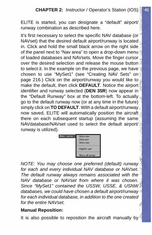
ELITE is started, you can designate a “default” airport/runway combination as described here.It’s fi rst necessary to select the specifi c NAV database (or NAVset) that the desired default airport/runway is lo cat ed in. Click and hold the small black arrow on the right side of the panel next to “Nav area” to open a drop-down menu of load ed databases and NAVsets. Move the fi n ger cursor over the desired selection and release the mouse button to select it. In the example on the previous page, we have cho sen to use “MySet1” (see “Creating NAV Sets” on page 216.) Click on the air port/run way you would like to make the default, then click DEFAULT. Notice the air port iden ti fi er and runway se lect ed (DEN 35R) now ap pear in the “Default Runway” box at the bottom-left. To actually go to the default run way now (or at any time in the fu ture) simply click on TO DEFAULT. With a default air port/run way now saved, ELITE will au to mat i cal ly position the aircraft there on each sub se quent startup (as sum ing the same NAVdatabase/NAVset used to select the default air port/runway is utilized).
NOTE: You may choose one pre ferred (de fault) run way for each and ev ery in di vid u al NAV da ta base or NAVset. The de fault run way al ways re mains as so ci at ed with the NAV da ta base or NAVset from where it was chosen. Since “MySet1” contained the USSW, USSE, & USNW da ta bas es, we could have chosen a default air port/runway for each individual database, in ad di tion to the one cre at ed for the entire NAVset. Manual Reposition:It is also possible to reposition the air craft man u al ly by
RC-1 OPERATOR’S MANUAL42
drag ging the aircraft symbol to a new lo ca tion.Do this by click ing on the aircraft symbol and mov ing the mouse while holding the mouse button.
If the desired new lo ca tion is outside the cur rent vis i ble MAP area, the MAP will start scroll ing when the aircraft sym bol is brought to ward the edge of the screen using the method de scribed above.
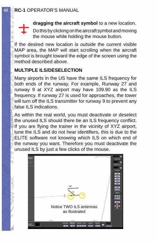
MULTIPLE ILS/DESELECTIONMany airports in the US have the same ILS frequency for both ends of the runway. For example, Runway 27 and runway 9 at XYZ airport may have 109.90 as the ILS frequency. If runway 27 is used for approaches, the tower will turn off the ILS transmitter for runway 9 to prevent any false ILS indications.As within the real world, you must deactivate or deselect the unused ILS should there be an ILS frequency confl ict. If you are fl ying the trainer in the vicinity of XYZ airport, tune the ILS and do not hear identifi ers, this is due to the ELITE software not knowing which ILS on which end of the runway you want. Therefore you must deactivate the unused ILS by just a few clicks of the mouse.
Notice TWO ILS antennas as illustrated
43CHAPTER 2: Instructor / Operator’s Station (IOS)
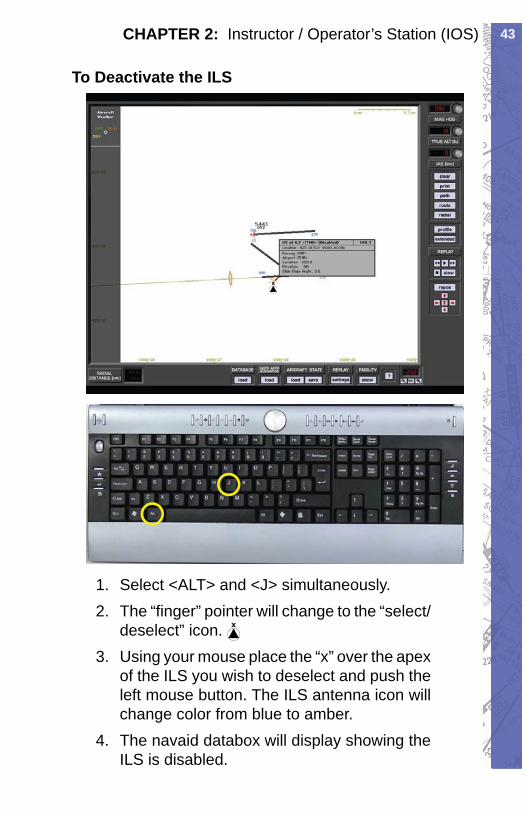
To Deactivate the ILS
Select <ALT> and <J> simultaneously.1. The “fi nger” pointer will change to the “select/2. deselect” icon. Using your mouse place the “x” over the apex 3. of the ILS you wish to deselect and push the left mouse button. The ILS antenna icon will change color from blue to amber.The navaid databox will display showing the 4. ILS is disabled.
RC-1 OPERATOR’S MANUAL44
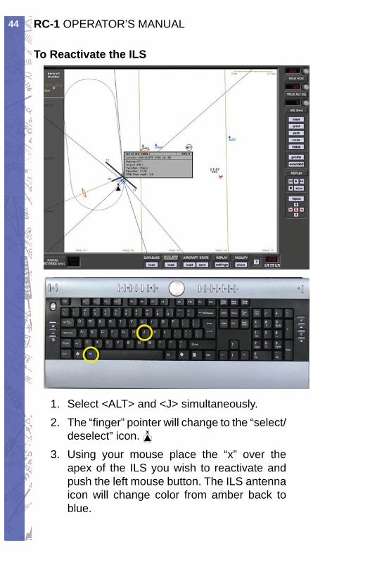
To Reactivate the ILS
Select <ALT> and <J> simultaneously.1. The “fi nger” pointer will change to the “select/2. deselect” icon. Using your mouse place the “x” over the 3. apex of the ILS you wish to reactivate and push the left mouse button. The ILS antenna icon will change color from amber back to blue.
45CHAPTER 2: Instructor / Operator’s Station (IOS)
The navaid databox will display showing the 4. ILS is now enabled.
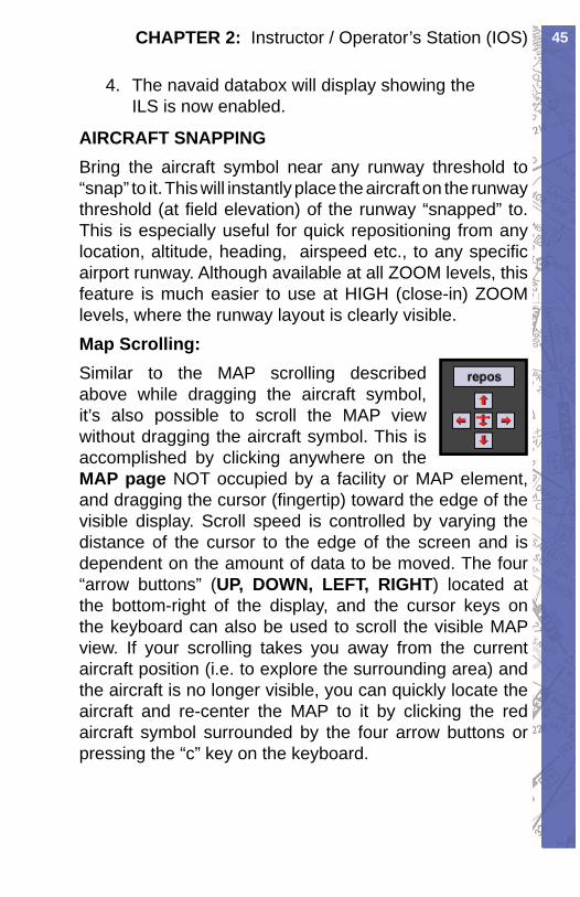
AIRCRAFT SNAPPINGBring the aircraft symbol near any runway thresh old to “snap” to it. This will instantly place the air craft on the runway threshold (at fi eld elevation) of the runway “snapped” to. This is especially use ful for quick re po si tion ing from any location, al ti tude, head ing, air speed etc., to any specifi c airport runway. Al though avail able at all ZOOM lev els, this feature is much eas i er to use at HIGH (close-in) ZOOM lev els, where the run way lay out is clearly visible. Map Scrolling:Similar to the MAP scrolling described above while dragging the aircraft symbol, it’s also pos si ble to scroll the MAP view without dragging the air craft sym bol. This is accomplished by clicking any where on the MAP page NOT occupied by a facility or MAP element, and dragging the cursor (fi ngertip) toward the edge of the visible display. Scroll speed is controlled by vary ing the distance of the cursor to the edge of the screen and is de pen dent on the amount of data to be moved. The four “ar row but tons” (UP, DOWN, LEFT, RIGHT) lo cat ed at the bot tom-right of the dis play, and the cur sor keys on the key board can also be used to scroll the vis i ble MAP view. If your scroll ing takes you away from the current air craft po si tion (i.e. to explore the sur round ing area) and the air craft is no longer vis i ble, you can quick ly locate the air craft and re-center the MAP to it by click ing the red air craft sym bol sur round ed by the four ar row but tons or press ing the “c” key on the key board.
RC-1 OPERATOR’S MANUAL46
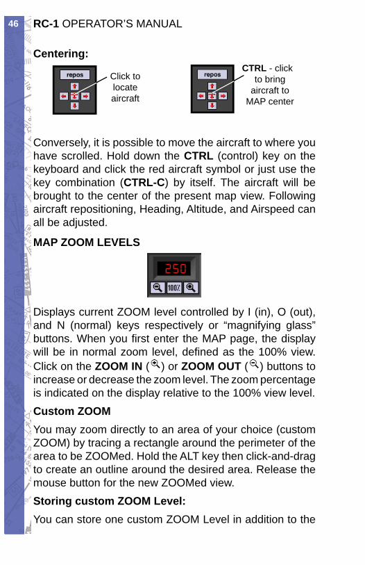
Centering:
Click tolocateaircraft
CTRL - click to bring
aircraft to MAP center
Conversely, it is possible to move the air craft to where you have scrolled. Hold down the CTRL (control) key on the keyboard and click the red air craft sym bol or just use the key combination (CTRL-C) by itself. The air craft will be brought to the center of the present map view. Following aircraft repositioning, Heading, Al ti tude, and Airspeed can all be ad just ed.
MAP ZOOM LEVELS
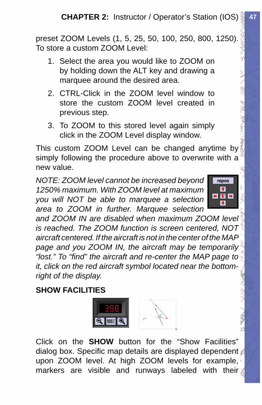
Displays current ZOOM level controlled by I (in), O (out), and N (normal) keys respectively or “mag ni fy ing glass” buttons. When you fi rst en ter the MAP page, the dis play will be in normal zoom lev el, de fi ned as the 100% view. Click on the ZOOM IN ( ) or ZOOM OUT ( ) buttons to in crease or decrease the zoom level. The zoom percentage is indicated on the display relative to the 100% view level. Custom ZOOMYou may zoom directly to an area of your choice (cus tom ZOOM) by trac ing a rectangle around the pe rim e ter of the area to be ZOOMed. Hold the ALT key then click-and-drag to create an out line around the desired area. Re lease the mouse but ton for the new ZOOMed view. Storing custom ZOOM Level:You can store one custom ZOOM Level in addition to the
47CHAPTER 2: Instructor / Operator’s Station (IOS)
preset ZOOM Levels (1, 5, 25, 50, 100, 250, 800, 1250). To store a custom ZOOM Level:
Select the area you would like to ZOOM on 1. by hold ing down the ALT key and drawing a marquee around the desired area.CTRL-Click in the ZOOM level window to 2. store the custom ZOOM level created in previous step.To ZOOM to this stored level again simply 3. click in the ZOOM Level display window.
This custom ZOOM Level can be changed anytime by simply following the procedure above to over write with a new value.NOTE: ZOOM level cannot be in creased beyond 1250% maximum. With ZOOM level at maximum you will NOT be able to marquee a se lec tion area to ZOOM in further. Mar quee selection and ZOOM IN are dis abled when max i mum ZOOM level is reached. The ZOOM func tion is screen cen tered, NOT air craft cen tered. If the air craft is not in the center of the MAP page and you ZOOM IN, the aircraft may be tem po rari ly “lost.” To “fi nd” the air craft and re-cen ter the MAP page to it, click on the red air craft sym bol lo cat ed near the bottom-right of the dis play.
SHOW FACILITIES
Click on the SHOW but ton for the “Show Fa cil i ties” dialog box. Specifi c map details are dis played de pen dent upon ZOOM lev el. At high ZOOM levels for ex am ple, mark ers are visible and runways labeled with their
RC-1 OPERATOR’S MANUAL48
mag net ic direction. At lower ZOOM levels, cer tain map el e ments (fa cil i ties) are not dis played to pre vent clutter and main tain map readability.
NOTE: You may determine which MAP elements (fa cil i ties) are displayed for corresponding ZOOM lev els.Click on the appropriate buttons to activate or deactivate the information to be shown in each ZOOM lev el. Yellow buttons indicate an active button.
Click OK and your selections will take • ef fect.Click CANCEL to return to the Map with no • chang es.Click STANDARD for a preset of active • fa cil i ties.
TRANSPONDER TAG
49CHAPTER 2: Instructor / Operator’s Station (IOS)
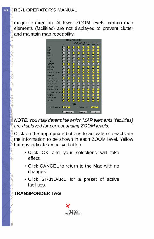
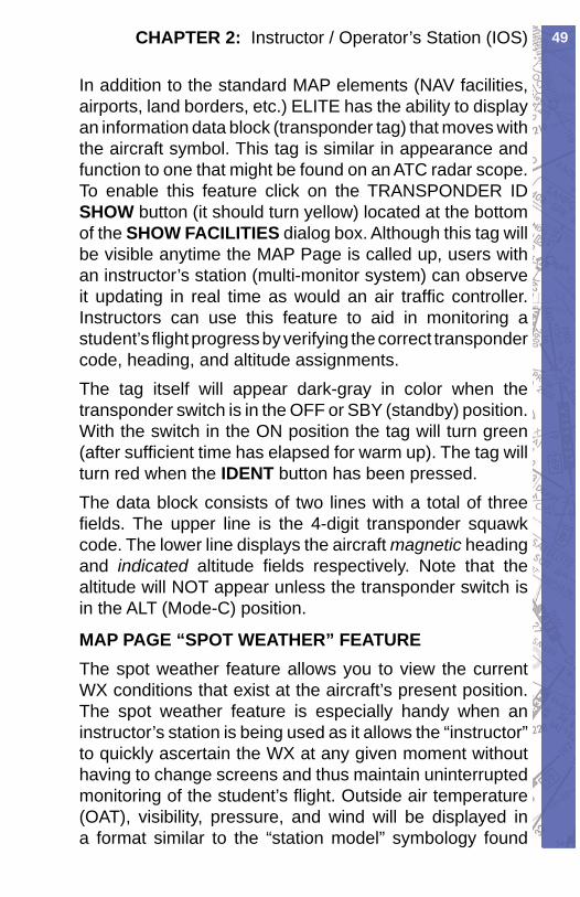
In addition to the standard MAP elements (NAV fa cil i ties, air ports, land bor ders, etc.) ELITE has the ability to display an in for ma tion data block (tran spon der tag) that moves with the air craft symbol. This tag is sim i lar in ap pear ance and function to one that might be found on an ATC radar scope. To enable this feature click on the TRANSPONDER ID SHOW button (it should turn yellow) located at the bottom of the SHOW FA CIL I TIES di a log box. Al though this tag will be visible any time the MAP Page is called up, users with an in struc tor’s station (multi-mon i tor system) can ob serve it updating in real time as would an air traffi c con trol ler. Instructors can use this feature to aid in mon i tor ing a stu dent’s fl ight progress by verifying the correct tran spon der code, heading, and altitude assignments.The tag itself will appear dark-gray in color when the tran spon der switch is in the OFF or SBY (standby) position. With the switch in the ON position the tag will turn green (after suf fi cient time has elapsed for warm up). The tag will turn red when the IDENT but ton has been pressed.The data block consists of two lines with a total of three fi elds. The upper line is the 4-digit transponder squawk code. The low er line dis plays the aircraft magnetic head ing and indicated altitude fi elds re spec tive ly. Note that the al ti tude will NOT appear unless the transponder switch is in the ALT (Mode-C) position.
MAP PAGE “ SPOT WEATHER” FEATUREThe spot weather feature allows you to view the current WX conditions that exist at the aircraft’s present position. The spot weather feature is especially handy when an instructor’s station is being used as it allows the “instructor” to quickly ascertain the WX at any given moment without having to change screens and thus maintain uninterrupted monitoring of the student’s fl ight. Outside air temperature (OAT), visibility, pressure, and wind will be displayed in a format similar to the “station model” symbology found
RC-1 OPERATOR’S MANUAL50
on Surface Analysis charts. Please note that the reported pressure is the actual ambient pressure (not altimeter setting) at the aircraft’s current altitude. Wind speed and direction are displayed graphically using a barb and fl ag system (see fi gure on page 105) connected to a “pole” that points in the direction FROM which the wind is blowing relative to True North. In the following example, the aircraft is at 3500 feet, wind is from the southeast at 15 knots, OAT is 47° Fahrenheit, ambient pressure is 26.34 inches, and visibility is 25 statute miles. Note that unlike the station model used on Surface Analysis charts, no sky cover information is provided.
To turn ON/OFF aircraft spot weather simply click the FACILITY “show” button at the bottom of the MAP Page. On the “Show Facilities” dialog box click on the Aircraft Info “SHOW” button. This button is an ON/OFF toggle that will turn yellow when pushed in (ON). The spot weather data appears at the upper-left corner of the MAP Page at the top of the shaded information display region.
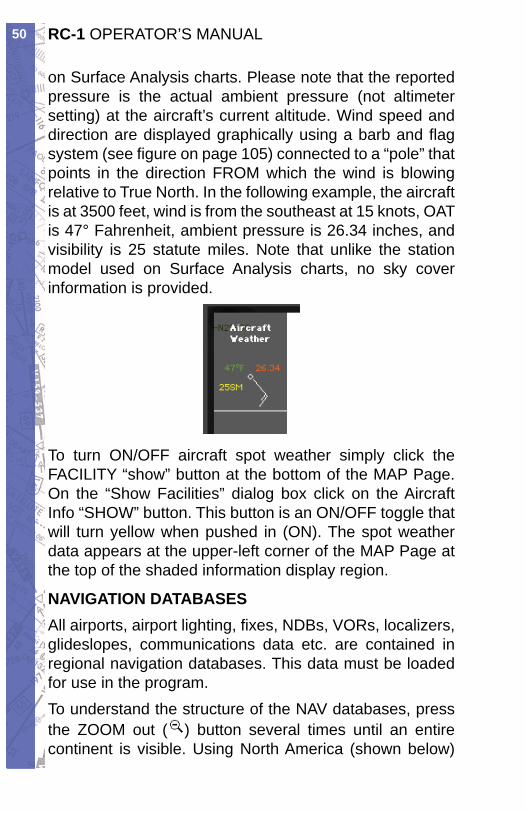
NAVIGATION DATABASESAll airports, airport lighting, fi xes, NDBs, VORs, localizers, glideslopes, com mu ni ca tions data etc. are contained in regional navigation da ta bas es. This data must be loaded for use in the program.To understand the structure of the NAV databases, press the ZOOM out ( ) button several times until an en tire continent is visible. Using North America (shown below)
51CHAPTER 2: Instructor / Operator’s Station (IOS)
for example, notice there are boxes visible across the U.S. that defi ne the regional boundaries of each NAV database. From this same view you can also determine if a spe cifi c NAV da ta base (region) is load ed. Gray box es in di cate data is available but not load ed. Red boxes in di cate the data with in its bound ary is load ed and ready for use.Note: Each NAV da ta base (re gion) is labeled for iden ti fi ca tion. The label (USNW) shown be low is for the Unit ed States North West.
NAV DATA Disclaimer: We do our best to ensure the ac cu ra cy of the NAV data in the software. Un for tu nate ly, in ac cu ra cies orig i nat ing from the data source are be yond our control and may be encountered at some point over time in the nor mal course of using the product. If you do encounter data that you feel is in error please make a note and let us know. The more in for ma tion you can gather about the specifi cs of your ex pe ri ence, the better. Make note of data that is suspected missing, in ac cu rate, er ro ne ous, or otherwise anom a lous and notify us with the de tails. Thanks!
RC-1 OPERATOR’S MANUAL52
Click and hold for
info
Click and hold for database
options
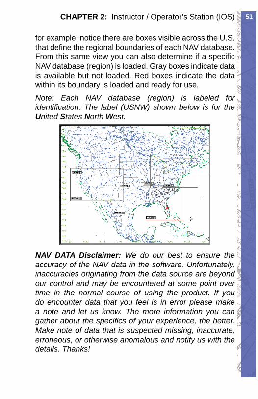
Click and hold the mouse on USNW part of label for de tailed in for ma tion on that database.
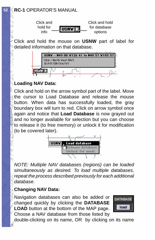
Loading NAV Data:Click and hold on the arrow symbol part of the label. Move the cur sor to Load Database and release the mouse button. When data has suc cess ful ly load ed, the gray bound ary box will turn to red. Click on arrow sym bol once again and notice that Load Database is now grayed out and no longer avail able for se lec tion but you can choose to release it (to free mem o ry) or un lock it for mod i fi ca tion (to be cov ered later).
NOTE: Multiple NAV databases (regions) can be load ed simultaneously as desired. To load multiple da ta bas es, repeat the pro cess described previously for each additional da ta base. Changing NAV Data:Navigation databases can also be added or changed quickly by clicking the DATABASE LOAD button at the bottom of the MAP page. Choose a NAV database from those list ed by double-clicking on its name, OR by clicking on its name
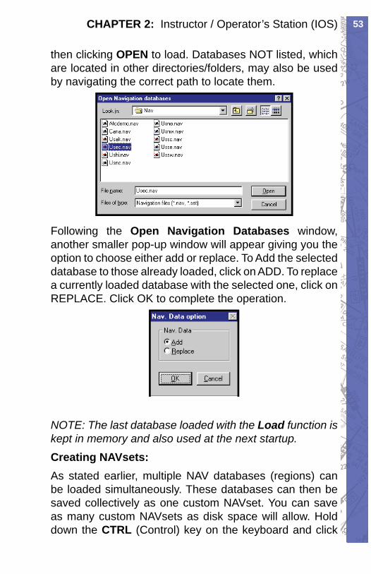
53CHAPTER 2: Instructor / Operator’s Station (IOS)
then clicking OPEN to load. Databases NOT listed, which are located in other directories/fold ers, may also be used by navigating the correct path to lo cate them.
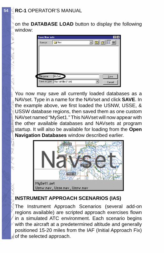
Following the Open Navigation Databases window, another smaller pop-up window will appear giving you the option to choose either add or replace. To Add the selected database to those already loaded, click on ADD. To replace a currently load ed database with the se lect ed one, click on REPLACE. Click OK to complete the operation.
NOTE: The last database loaded with the Load func tion is kept in memory and also used at the next startup.Creating NAVsets:As stated earlier, multiple NAV databases (regions) can be loaded si mul ta neous ly. These databases can then be saved collectively as one custom NAVset. You can save as many custom NAVsets as disk space will allow. Hold down the CTRL (Con trol) key on the keyboard and click
RC-1 OPERATOR’S MANUAL54
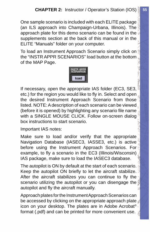
on the DATABASE LOAD but ton to dis play the fol low ing win dow:
You now may save all currently loaded databases as a NAVset. Type in a name for the NAVset and click SAVE. In the example above, we fi rst loaded the USNW, USSE, & USSW database regions, then saved them as one cus tom NAVset named “MySet1.” This NAVset will now appear with the oth er avail able da ta bas es and NAVsets at program startup. It will also be avail able for loading from the Open Navigation Da ta bas es win dow described ear li er.
INSTRUMENT APPROACH SCENARIOS (IAS)The Instrument Approach Scenarios (several add-on regions available) are scripted approach exercises fl own in a simulated ATC environment. Each scenario begins with the aircraft at a predetermined altitude and generally positioned 15-20 miles from the IAF (Initial Approach Fix) of the selected approach.
55CHAPTER 2: Instructor / Operator’s Station (IOS)
One sample scenario is included with each ELITE package (an ILS approach into Champaign-Urbana, Illinois). The approach plate for this demo scenario can be found in the supplements section at the back of this manual or in the ELITE “Manuals” folder on your computer. To load an Instrument Approach Scenario simply click on the “INSTR APPR SCENARIOS” load button at the bottom of the MAP Page.
If necessary, open the appropriate IAS folder (EC3, SE3, etc.) for the region you would like to fl y in. Select and open the desired Instrument Approach Scenario from those listed. NOTE: A description of each scenario can be viewed (before it is opened) by highlighting any scenario fi le name with a SINGLE MOUSE CLICK. Follow on-screen dialog box instructions to start scenario.Important IAS notes:Make sure to load and/or verify that the appropriate Navigation Database (IASEC3, IASSE3, etc.) is active before using the Instrument Approach Scenarios. For example, to fl y a scenario in the EC3 (Illinois/Wisconsin) IAS package, make sure to load the IASEC3 database. The autopilot is ON by default at the start of each scenario. Keep the autopilot ON briefl y to let the aircraft stabilize. After the aircraft stabilizes you can continue to fl y the scenario utilizing the autopilot or you can disengage the autopilot and fl y the aircraft manually.Approach plates for the Instrument Approach Scenarios can be accessed by clicking on the appropriate approach plate icon on your desktop. The plates are in Adobe Acrobat®
format (.pdf) and can be printed for more convenient use.
RC-1 OPERATOR’S MANUAL56
Whenever the program requires your attention you will hear a series of alert tones. When these tones are heard, direct your attention to the information display area along the top of the screen for more information.CTRL-RPress CTRL-R to repeat the last ATC transmission directed at your aircraft. Your aircraft identifi cation throughout the scenarios will always be N054EG. Listen carefully for this call sign and follow ATC’s instructions to properly execute the approach.CTRL-KPress CTRL-K to acknowledge and/or answer a request from the program. One example of this might be if a controller asks you to “report fi eld in sight.” Since there is no way to actually converse with the virtual controllers, CTRL-K is used by the program as a communication trigger. This is similar to a quick double-click of a push-to-talk switch in a real aircraft (sometimes requested by ATC to verify communication). CTRL-SPress CTRL-S to disable the automatic setting of radios by the virtual instructor (see next section). Instructor Help:At the beginning of the each scenario the program will ask if you would like to have the help of an instructor. By answering “yes” to this option you will be inviting a virtual instructor into the cockpit. The virtual instructor will act more like the copilot or PNF (pilot not fl ying) in these scenarios, setting up essential radios and thus taking some of the workload. The virtual instructor will also provide tips along the way when appropriate which, will be displayed at the top of the screen in the information display area. Always
57CHAPTER 2: Instructor / Operator’s Station (IOS)
make sure to stay in the loop and check the inputs of the virtual instructor!
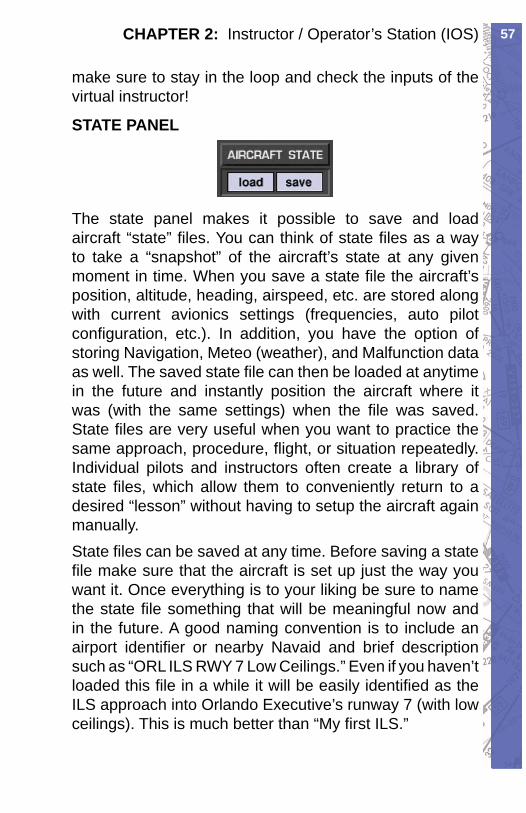
STATE PANEL
The state panel makes it possible to save and load aircraft “state” fi les. You can think of state fi les as a way to take a “snapshot” of the aircraft’s state at any given moment in time. When you save a state fi le the aircraft’s position, altitude, heading, airspeed, etc. are stored along with current avionics settings (frequencies, auto pilot confi guration, etc.). In addition, you have the option of storing Navigation, Meteo (weather), and Malfunction data as well. The saved state fi le can then be loaded at anytime in the future and instantly position the aircraft where it was (with the same settings) when the fi le was saved. State fi les are very useful when you want to practice the same approach, procedure, fl ight, or situation repeatedly. Individual pilots and instructors often create a library of state fi les, which allow them to conveniently return to a desired “lesson” without having to setup the aircraft again manually. State fi les can be saved at any time. Before saving a state fi le make sure that the aircraft is set up just the way you want it. Once everything is to your liking be sure to name the state fi le something that will be meaningful now and in the future. A good naming convention is to include an airport identifi er or nearby Navaid and brief description such as “ORL ILS RWY 7 Low Ceilings.” Even if you haven’t loaded this fi le in a while it will be easily identifi ed as the ILS approach into Orlando Executive’s runway 7 (with low ceilings). This is much better than “My fi rst ILS.”
RC-1 OPERATOR’S MANUAL58
HEADING PANEL
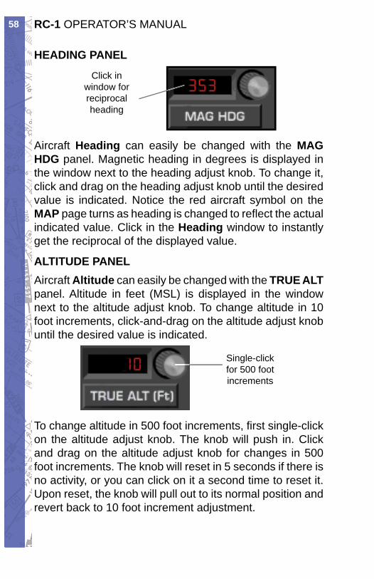
Click inwindow for reciprocal heading
Aircraft Heading can easily be changed with the MAG HDG pan el. Mag net ic head ing in de grees is dis played in the win dow next to the head ing ad just knob. To change it, click and drag on the head ing adjust knob until the de sired val ue is in di cat ed. Notice the red air craft sym bol on the MAP page turns as heading is changed to re fl ect the ac tu al indicated value. Click in the Heading window to in stant ly get the reciprocal of the displayed value.
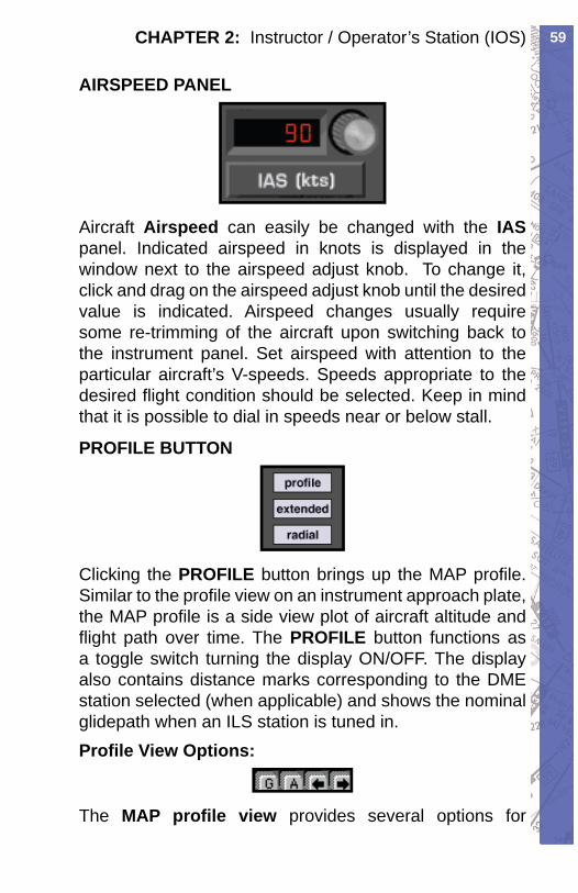
ALTITUDE PANELAircraft Altitude can easily be changed with the TRUE ALT panel. Altitude in feet (MSL) is displayed in the window next to the altitude adjust knob. To change al ti tude in 10 foot in cre ments, click-and-drag on the al ti tude adjust knob until the desired val ue is indicated.
Single-click for 500 foot increments
To change altitude in 500 foot increments, fi rst single-click on the altitude adjust knob. The knob will push in. Click and drag on the altitude adjust knob for chang es in 500 foot increments. The knob will re set in 5 seconds if there is no ac tiv i ty, or you can click on it a second time to reset it. Upon reset, the knob will pull out to its normal position and re vert back to 10 foot increment adjustment.
59CHAPTER 2: Instructor / Operator’s Station (IOS)
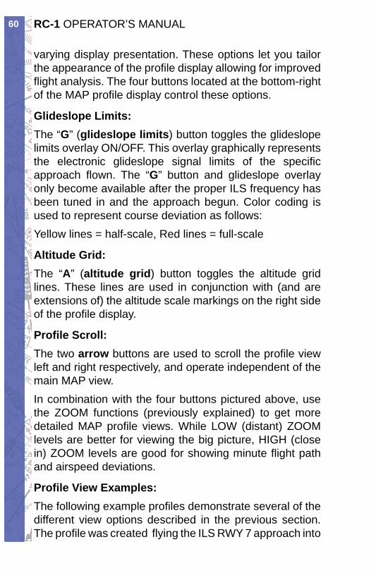
AIRSPEED PANEL
Aircraft Airspeed can easily be changed with the IASpanel. Indicated air speed in knots is displayed in the window next to the airspeed adjust knob. To change it, click and drag on the airspeed adjust knob until the desired value is in di cat ed. Airspeed changes usually require some re-trim ming of the aircraft upon switch ing back to the in stru ment pan el. Set air speed with at ten tion to the par tic u lar air craft’s V-speeds. Speeds ap pro pri ate to the de sired fl ight condition should be se lect ed. Keep in mind that it is pos si ble to dial in speeds near or be low stall.
PROFILE BUTTON
Clicking the PRO FILE button brings up the MAP pro fi le. Similar to the profi le view on an in stru ment ap proach plate, the MAP profi le is a side view plot of air craft altitude and fl ight path over time. The PRO FILE but ton func tions as a toggle switch turning the dis play ON/OFF. The display also contains dis tance marks cor re spond ing to the DME station se lect ed (when ap pli ca ble) and shows the nom i nal glidepath when an ILS sta tion is tuned in.Profi le View Options:
The MAP profi le view pro vides sev er al options for
RC-1 OPERATOR’S MANUAL60
varying dis play pre sen ta tion. These op tions let you tai lor the ap pear ance of the profi le dis play al low ing for improved fl ight anal y sis. The four buttons lo cat ed at the bottom-right of the MAP profi le display control these options.
Glideslope Limits:The “G” (glideslope limits) but ton toggles the glideslope limits overlay ON/OFF. This overlay graph i cal ly represents the electronic glideslope signal limits of the specifi c approach fl own. The “G” button and glideslope over lay only become available after the prop er ILS fre quen cy has been tuned in and the ap proach be gun. Color coding is used to represent course de vi a tion as fol lows:Yellow lines = half-scale, Red lines = full-scale
Altitude Grid:The “A” (altitude grid) button toggles the altitude grid lines. These lines are used in con junc tion with (and are extensions of) the al ti tude scale markings on the right side of the profi le display.
Profi le Scroll:The two arrow buttons are used to scroll the profi le view left and right respectively, and operate in de pen dent of the main MAP view.In combination with the four buttons pictured above, use the ZOOM functions (previously explained) to get more detailed MAP profi le views. While LOW (dis tant) ZOOM levels are better for viewing the big pic ture, HIGH (close in) ZOOM lev els are good for show ing minute fl ight path and airspeed deviations.
Profi le View Examples:The following example profi les dem on strate sev er al of the different view options de scribed in the previous section. The profi le was created fl ying the ILS RWY 7 approach into
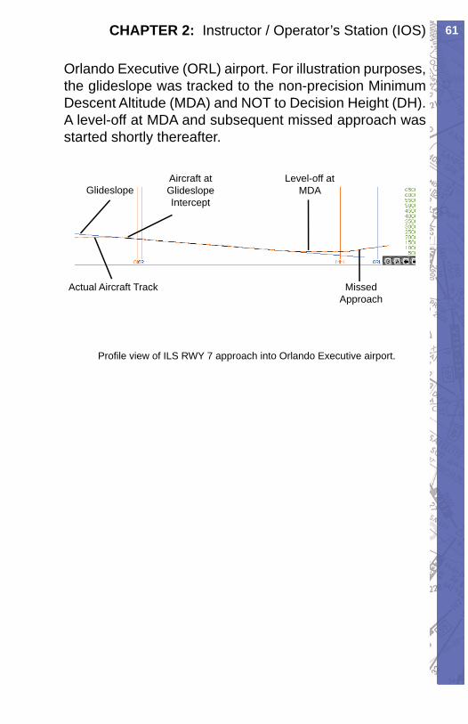
61CHAPTER 2: Instructor / Operator’s Station (IOS)
Orlando Executive (ORL) airport. For illustration purposes, the glideslope was tracked to the non-pre ci sion Min i mum Descent Altitude (MDA) and NOT to Decision Height (DH). A level-off at MDA and subsequent missed ap proach was start ed short ly there af ter.
Level-off at MDA
Aircraft at Glideslope Intercept
Glideslope
Missed Approach
Actual Aircraft Track
Profi le view of ILS RWY 7 approach into Orlando Executive airport.
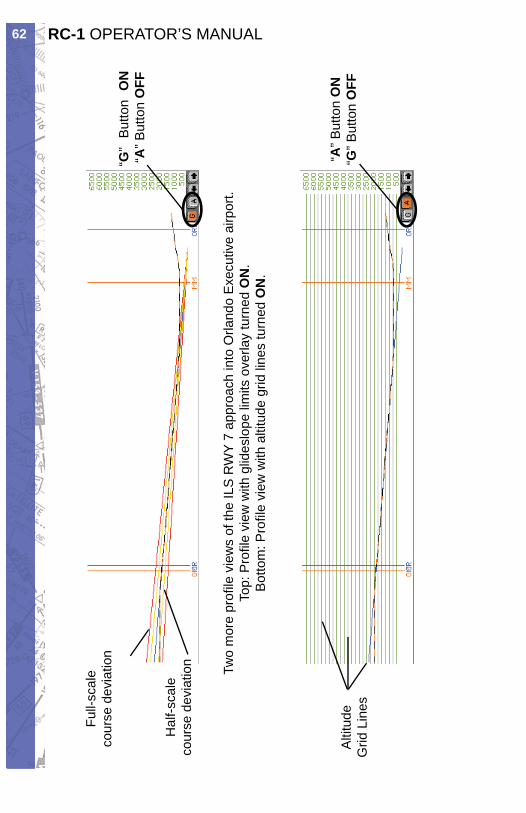
RC-1 OPERATOR’S MANUAL62
Two
mor
e pr
ofi le
vie
ws
of th
e IL
S R
WY
7 ap
proa
ch in
to O
rland
o E
xecu
tive
airp
ort.
Top:
Pro
fi le
view
with
glid
eslo
pe li
mits
ove
rlay
turn
ed O
N.
Bot
tom
: Pro
fi le
view
with
alti
tude
grid
line
s tu
rned
ON
.
Full-
scal
eco
urse
dev
iatio
n
Hal
f-sca
leco
urse
dev
iatio
n
Alti
tude
Grid
Lin
es
“G”
But
ton
ON
“A” B
utto
n O
FF
“A” B
utto
n O
N“G
” But
ton
OFF
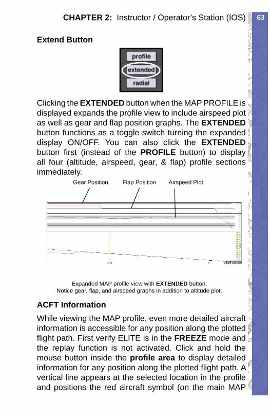
63CHAPTER 2: Instructor / Operator’s Station (IOS)
Extend Button
Clicking the EXTENDED but ton when the MAP PRO FILE is displayed expands the pro fi le view to include air speed plot as well as gear and fl ap po si tion graphs. The EX TEND EDbut ton func tions as a tog gle switch turn ing the ex pand ed display ON/OFF. You can also click the EX TEND EDbutton fi rst (in stead of the PROFILE but ton) to dis play all four (altitude, air speed, gear, & fl ap) pro fi le sections immediately.
Expanded MAP profi le view with EXTENDED button. Notice gear, fl ap, and airspeed graphs in addition to altitude plot.
Gear Position Flap Position Airspeed Plot
ACFT InformationWhile viewing the MAP profi le, even more detailed aircraft information is accessible for any position along the plotted fl ight path. First ver i fy ELITE is in the FREEZE mode and the replay function is not ac ti vat ed. Click and hold the mouse but ton in side the profi le area to dis play de tailed in for ma tion for any po si tion along the plot ted fl ight path. A vertical line appears at the se lect ed location in the pro fi le and po si tions the red air craft symbol (on the main MAP
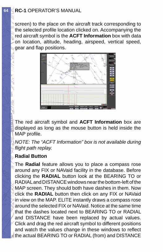
RC-1 OPERATOR’S MANUAL64
screen) to the place on the aircraft track cor re spond ing to the selected pro fi le location clicked on. Accompanying the red aircraft sym bol is the ACFT Information box with data on lo ca tion, altitude, head ing, airspeed, vertical speed, gear and fl ap positions.
The red aircraft symbol and ACFT Information box are displayed as long as the mouse button is held in side the MAP profi le.NOTE: The “ACFT Information” box is not available during fl ight path replay.Radial ButtonThe Radial fea ture allows you to place a com pass rose around any FIX or NAVaid fa cil i ty in the database. Be fore click ing the RADIAL button look at the BEARING TO or RA DI AL and DIS TANCE win dows near the bot tom-left of the MAP screen. They should both have dashes in them. Now click the RA DI AL but ton then click on any FIX or NAVaid in view on the MAP. ELITE in stant ly draws a com pass rose around the se lect ed FIX or NAVaid. Notice at the same time that the dash es lo cat ed next to BEAR ING TO or RA DI AL and DIS TANCE have been re placed by ac tu al values. Click and drag the red aircraft sym bol to dif fer ent po si tions and watch the values change in these win dows to re fl ect the actual BEAR ING TO or RA DI AL (from) and DIS TANCE
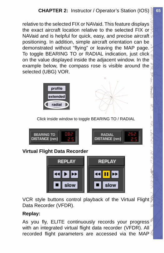
65CHAPTER 2: Instructor / Operator’s Station (IOS)
relative to the se lect ed FIX or NAVaid. This feature displays the exact aircraft lo ca tion rel a tive to the selected FIX or NAVaid and is helpful for quick, easy, and precise air craft positioning. In ad di tion, sim ple aircraft ori en ta tion can be dem on strat ed without “fl ying” or leav ing the MAP page. To tog gle BEARING TO or RADIAL in di ca tion, just click on the value dis played inside the ad ja cent window. In the example be low, the com pass rose is visible around the se lect ed (UBG) VOR.
Click inside window to toggle BEARING TO / RADIAL
Vir tu al Flight Data Re cord er
VCR style buttons control play back of the Virtual Flight Data Re cord er (VFDR). Replay:As you fl y, ELITE continuously records your progress with an integrated virtual fl ight data recorder (VFDR). All recorded fl ight parameters are accessed via the MAP
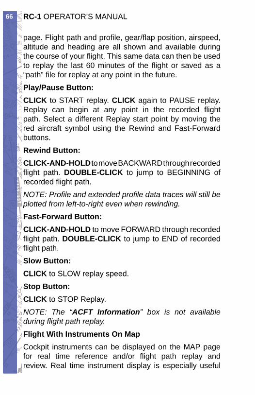
RC-1 OPERATOR’S MANUAL66
page. Flight path and profi le, gear/fl ap position, air speed, altitude and heading are all shown and available during the course of your fl ight. This same data can then be used to replay the last 60 minutes of the fl ight or saved as a “path” fi le for replay at any point in the future.Play/Pause Button:CLICK to START replay. CLICK again to PAUSE replay. Replay can begin at any point in the recorded fl ight path. Select a different Replay start point by moving the red aircraft symbol using the Rewind and Fast-Forward buttons.Rewind Button:CLICK-AND-HOLD to move BACKWARD through recorded fl ight path. DOUBLE-CLICK to jump to BEGINNING of recorded fl ight path.NOTE: Profi le and extended profi le data traces will still be plotted from left-to-right even when rewinding.Fast-Forward Button:CLICK-AND-HOLD to move FORWARD through recorded fl ight path. DOUBLE-CLICK to jump to END of recorded fl ight path.Slow Button:CLICK to SLOW replay speed.Stop Button:CLICK to STOP Replay.NOTE: The “ACFT In for ma tion” box is not avail able during fl ight path replay.Flight With Instruments On MapCockpit instruments can be displayed on the MAP page for real time reference and/or fl ight path replay and review. Real time instrument display is es pe cial ly use ful
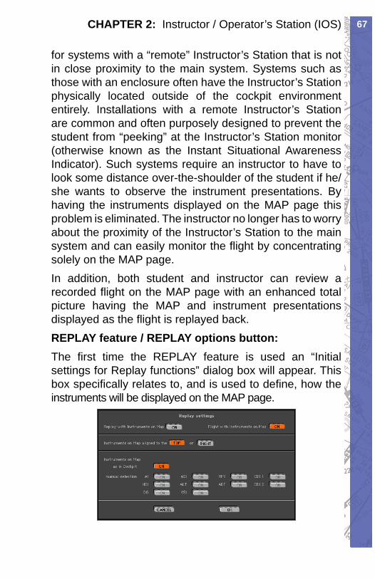
67CHAPTER 2: Instructor / Operator’s Station (IOS)
for systems with a “remote” In struc tor’s Station that is not in close proximity to the main system. Systems such as those with an enclosure often have the In struc tor’s Station phys i cal ly located outside of the cockpit en vi ron ment entirely. In stal la tions with a re mote In struc tor’s Station are common and often pur pose ly designed to prevent the student from “peek ing” at the In struc tor’s Station monitor (otherwise known as the Instant Situational Aware ness In di ca tor). Such systems require an instructor to have to look some dis tance over-the-shoulder of the stu dent if he/she wants to observe the instrument presentations. By having the instruments displayed on the MAP page this problem is eliminated. The instructor no longer has to worry about the prox im i ty of the Instructor’s Station to the main system and can easily monitor the fl ight by con cen trat ing solely on the MAP page.In addition, both student and instructor can review a recorded fl ight on the MAP page with an en hanced to tal picture having the MAP and in stru ment pre sen ta tions displayed as the fl ight is re played back.REPLAY feature / REPLAY options button:The fi rst time the REPLAY feature is used an “Initial settings for Replay functions” dialog box will appear. This box specifi cally relates to, and is used to defi ne, how the instruments will be dis played on the MAP page.
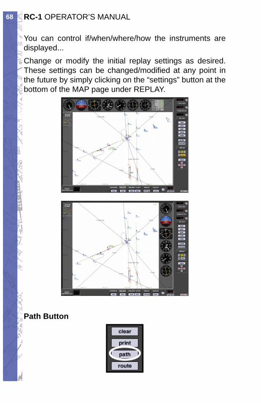
RC-1 OPERATOR’S MANUAL68
You can control if/when/where/how the in stru ments are displayed...Change or modify the ini tial replay set tings as de sired. These settings can be changed/modifi ed at any point in the future by sim ply clicking on the “set tings” button at the bottom of the MAP page under REPLAY.
Path Button
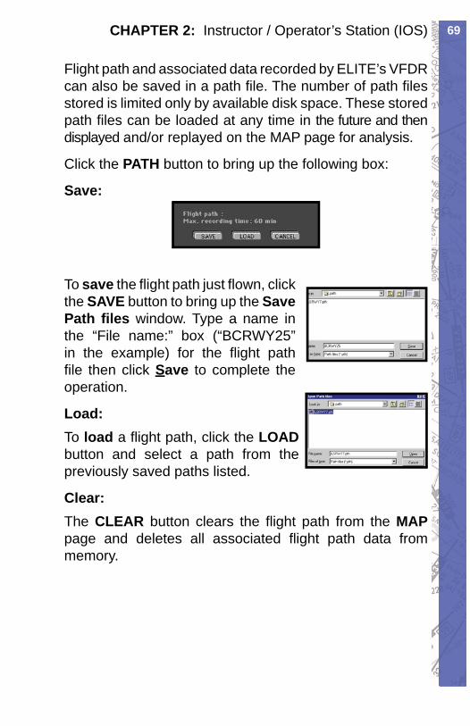
69CHAPTER 2: Instructor / Operator’s Station (IOS)
Flight path and as so ci at ed data re cord ed by ELITE’s VFDR can also be saved in a path fi le. The num ber of path fi les stored is lim it ed only by available disk space. These stored path fi les can be load ed at any time in the future and then displayed and/or re played on the MAP page for anal y sis.
Click the PATH button to bring up the following box:
Save:
To save the fl ight path just fl own, click the SAVE but ton to bring up the Save Path fi les win dow. Type a name in the “File name:” box (“BCRWY25” in the ex am ple) for the fl ight path fi le then click Save to com plete the op er a tion.
Load:To load a fl ight path, click the LOAD but ton and se lect a path from the pre vi ous ly saved paths listed.
Clear:The CLEAR button clears the fl ight path from the MAPpage and deletes all as so ci at ed fl ight path data from memory.
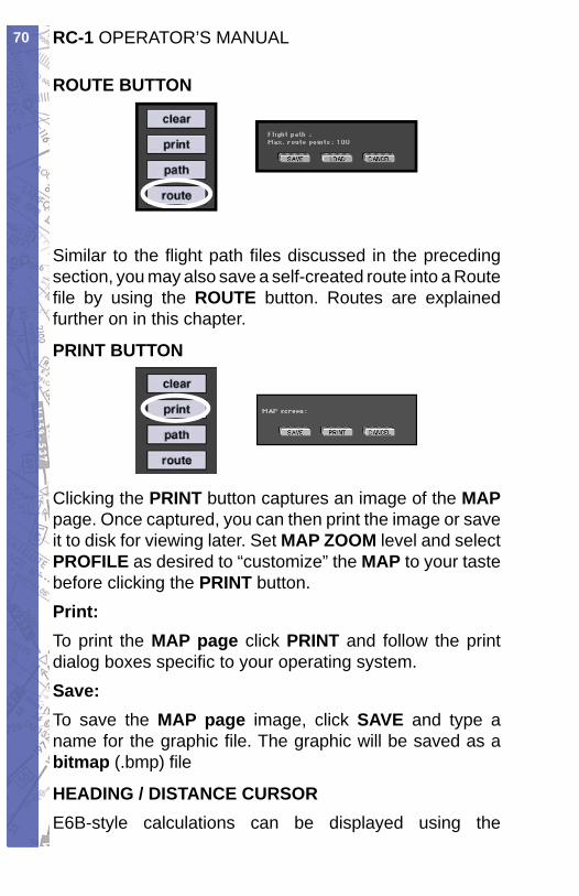
RC-1 OPERATOR’S MANUAL70
ROUTE BUTTON
Similar to the fl ight path fi les dis cussed in the pre ced ing section, you may also save a self-cre at ed route into a Route fi le by us ing the ROUTE but ton. Routes are ex plained fur ther on in this chap ter.
PRINT BUTTON
Clicking the PRINT but ton captures an image of the MAPpage. Once cap tured, you can then print the im age or save it to disk for viewing later. Set MAP ZOOM lev el and se lect PROFILE as desired to “customize” the MAP to your taste before click ing the PRINT but ton.Print:To print the MAP page click PRINT and fol low the print dialog boxes specifi c to your operating system.Save:To save the MAP page image, click SAVE and type a name for the graphic fi le. The graphic will be saved as a bitmap (.bmp) fi le
HEADING / DISTANCE CURSORE6B-style calculations can be displayed using the
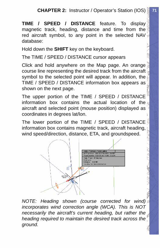
71CHAPTER 2: Instructor / Operator’s Station (IOS)
TIME / SPEED / DISTANCE feature. To dis play mag net ic track, heading, distance and time from the red aircraft symbol, to any point in the selected NAV database: Hold down the SHIFT key on the keyboard.The TIME / SPEED / DISTANCE cursor appears Click and hold anywhere on the Map page. An orange course line representing the desired track from the air craft symbol to the selected point will ap pear. In ad di tion, the TIME / SPEED / DIS TANCE in for ma tion box appears as shown on the next page.The upper portion of the TIME / SPEED / DIS TANCE information box contains the actual location of the air craft and selected point (mouse position) displayed as coordinates in degrees lat/lon. The lower portion of the TIME / SPEED / DIS TANCE information box contains magnetic track, aircraft head ing, wind speed/direction, distance, ETA, and ground speed.
NOTE: Heading shown (course corrected for wind) incorporates wind correction angle (WCA). This is NOT nec es sar i ly the aircraft’s current heading, but rather the heading required to maintain the desired track across the ground.
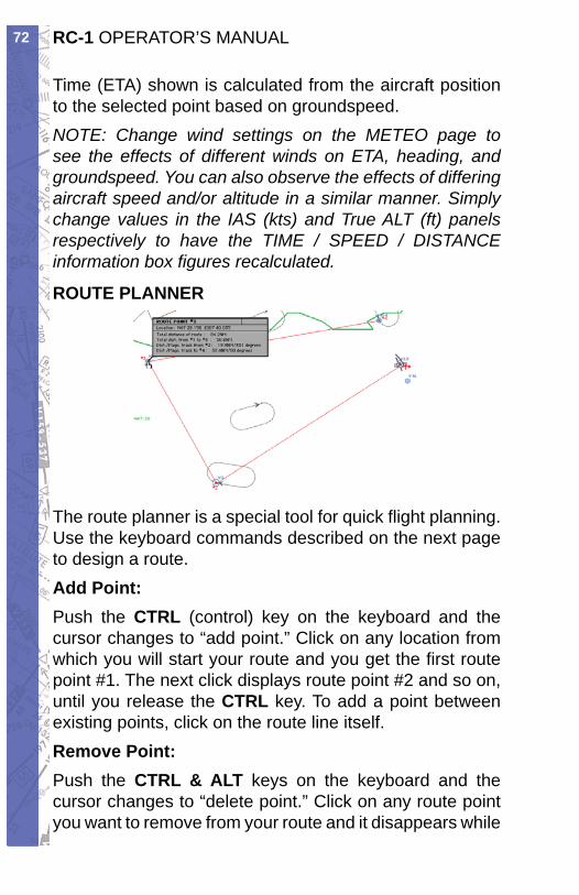
RC-1 OPERATOR’S MANUAL72
Time (ETA) shown is calculated from the aircraft po si tion to the selected point based on groundspeed. NOTE: Change wind settings on the METEO page to see the effects of different winds on ETA, heading, and ground speed. You can also observe the effects of dif fer ing aircraft speed and/or altitude in a similar man ner. Simply change values in the IAS (kts) and True ALT (ft) panels respectively to have the TIME / SPEED / DISTANCE information box fi gures re cal cu lat ed.
ROUTE PLANNER
The route planner is a special tool for quick fl ight plan ning. Use the keyboard commands described on the next page to design a route. Add Point:Push the CTRL (control) key on the keyboard and the cursor changes to “add point.” Click on any lo ca tion from which you will start your route and you get the fi rst route point #1. The next click displays route point #2 and so on, until you release the CTRL key. To add a point between existing points, click on the route line itself. Remove Point:Push the CTRL & ALT keys on the key board and the cur sor chang es to “de lete point.” Click on any route point you want to re move from your route and it disappears while
73CHAPTER 2: Instructor / Operator’s Station (IOS)
the oth er route points renumber.Move Point:Push the CTRL & SHIFT keys on the key board and the cursor changes to “move point.” Click on any route point you want to move and drag it with the mouse to another location. Re lease the mouse button and chang es take effect.Route Info:Click and hold on individual route points to get route and leg information. Point coordinates, as well as track and dis tance in for ma tion are displayed in an ac com pa ny ing win dow as long as the mouse but ton is held down.
SHORTCUTSTo display the Shortcuts In for ma tion window, click on the “?“ button. The Short cuts window will open and dis play all shortcuts (key combinations that en able certain functions).
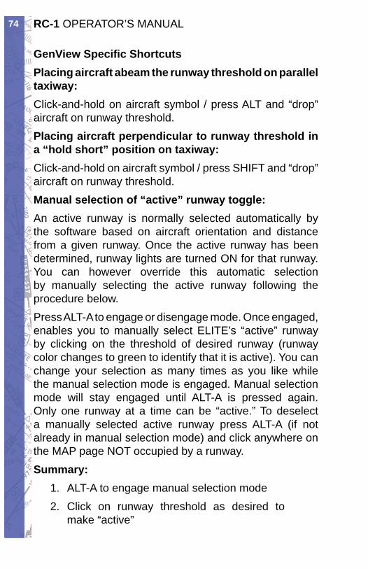
RC-1 OPERATOR’S MANUAL74
GenView Specifi c ShortcutsPlacing aircraft abeam the run way thresh old on parallel taxiway:Click-and-hold on aircraft symbol / press ALT and “drop” aircraft on runway threshold.Placing aircraft per pen dic u lar to runway thresh old in a “hold short” position on taxiway:Click-and-hold on air craft symbol / press SHIFT and “drop” aircraft on run way threshold.Manual selection of “active” runway toggle:An active runway is normally selected automatically by the software based on aircraft orientation and dis tance from a given runway. Once the active runway has been determined, runway lights are turned ON for that runway. You can however override this automatic selection by manually selecting the active runway fol low ing the procedure below. Press ALT-A to engage or disengage mode. Once en gaged, enables you to manually select ELITE’s “ac tive” runway by clicking on the threshold of de sired runway (run way color changes to green to iden ti fy that it is active). You can change your selection as many times as you like while the manual selection mode is engaged. Manual selection mode will stay engaged until ALT-A is pressed again. Only one runway at a time can be “active.” To deselect a manually selected active run way press ALT-A (if not already in manual selection mode) and click anywhere on the MAP page NOT occupied by a runway. Summary:
ALT-A to engage manual selection mode1. Click on runway threshold as desired to 2. make “active”
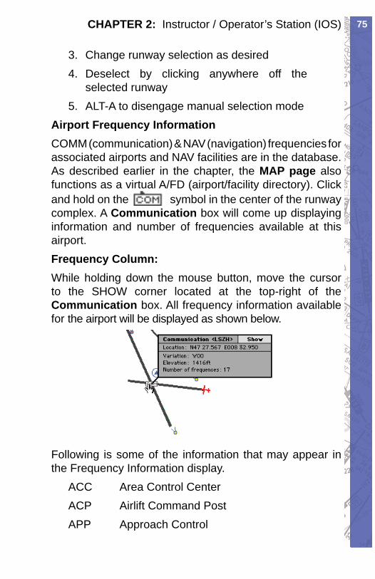
75CHAPTER 2: Instructor / Operator’s Station (IOS)
Change runway selection as desired3. Deselect by clicking anywhere off the 4. selected runwayALT-A to disengage manual selection mode5.
Airport Frequency InformationCOMM (communication) & NAV (navigation) fre quen cies for associated airports and NAV facilities are in the database. As described earlier in the chapter, the MAP page also functions as a virtual A/FD ( airport/facility directory). Click and hold on the sym bol in the center of the runway com plex. A Com mu ni ca tion box will come up displaying in for ma tion and number of fre quen cies avail able at this airport. Frequency Column:While holding down the mouse but ton, move the cur sor to the SHOW cor ner located at the top-right of the Communication box. All frequency information avail able for the airport will be displayed as shown below.
Following is some of the information that may appear in the Frequency Information display.
ACC Area Control CenterACP Air lift Command PostAPP Ap proach Control

RC-1 OPERATOR’S MANUAL76
ARR Arrival ControlATI Automatic Terminal Info. Service (ATIS)AWO Automatic Weather Observing Station (AWOS)CLD Clearance DeliveryCPT Clear ance Pre-TaxiCTL ControlDEP Departure ControlDIR Director (Approach Control/Radar)EMR EmergencyFSS Flight Service StationGND Ground ControlGTE Gate ControlHEL Helicopter FrequencyINF InformationMUL MulticomODP Parametres (French Radio)OPS OperationsRDO RadioRDR Radar Only FrequencyRFS Re mote Flight Service Station (RFSS)RMP Ramp / Taxi ControlRSA Air port Radar Service Area (ARSA)TCA Terminal Control AreaTRS Ter mi nal Radar Service Area (TRSA)TWE Transcribed Weather Broadcast (TWEB)TWR Air Traffi c Control Tower
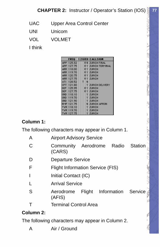
77CHAPTER 2: Instructor / Operator’s Station (IOS)
UAC Up per Area Control CenterUNI UnicomVOL VOLMETI think
Column 1:The following characters may ap pear in Col umn 1.
A Airport Advisory ServiceC Com mu ni ty Aerodrome Radio Station (CARS)D Departure ServiceF Flight Information Service (FIS)I Ini tial Contact (IC)L Arrival ServiceS Aerodrome Flight Information Service (AFIS)T Terminal Control Area
Column 2:The following characters may ap pear in Col umn 2.
A Air / Ground
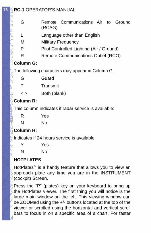
RC-1 OPERATOR’S MANUAL78
G Remote Com mu ni ca tions Air to Ground (RCAG)L Language other than EnglishM Mil i tary FrequencyP Pilot Con trolled Lighting (Air / Ground)R Remote Communications Outlet (RCO)
Column G:The following characters may ap pear in Col umn G.
G GuardT Transmit< > Both (blank)
Column R:This column indicates if radar ser vice is avail able:
R YesN No
Column H:Indicates if 24 hours service is available.
Y YesN No
HOTPLATESHotPlates™ is a handy feature that allows you to view an approach plate any time you are in the IN STRU MENT (cockpit) Screen. Press the “P” (plates) key on your keyboard to bring up the HotPlates viewer. The fi rst thing you will no tice is the large main window on the left. This viewing win dow can be ZOOMed using the +/- buttons lo cat ed at the top of the viewer or scrolled using the horizontal and vertical scroll bars to focus in on a specifi c area of a chart. For faster
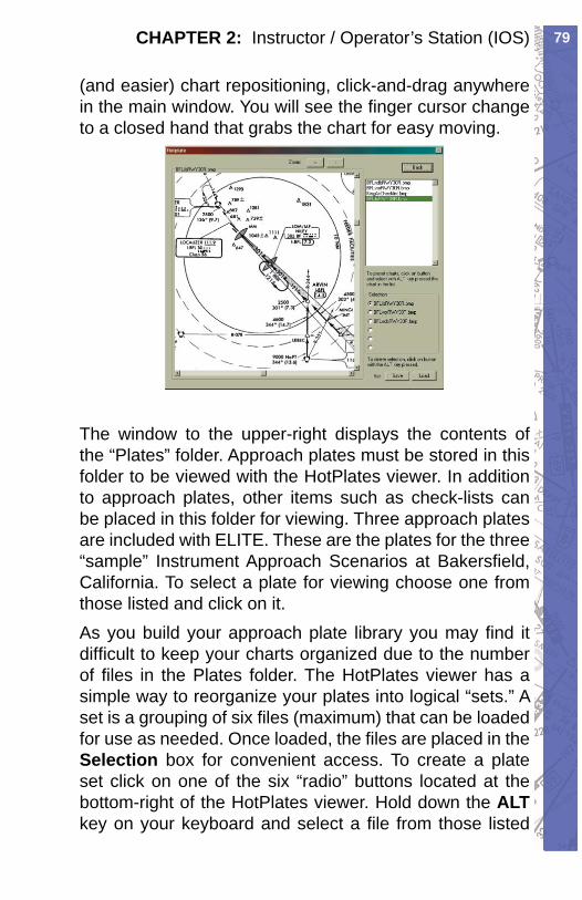
79CHAPTER 2: Instructor / Operator’s Station (IOS)
(and easier) chart re po si tion ing, click-and-drag anywhere in the main window. You will see the fi n ger cursor change to a closed hand that grabs the chart for easy mov ing.
The window to the upper-right dis plays the con tents of the “Plates” fold er. Approach plates must be stored in this folder to be viewed with the HotPlates viewer. In addition to approach plates, other items such as check-lists can be placed in this folder for viewing. Three ap proach plates are in clud ed with ELITE. These are the plates for the three “sam ple” Instrument Approach Scenarios at Bakers fi eld, Cal i for nia. To select a plate for viewing choose one from those listed and click on it.As you build your approach plate library you may fi nd it diffi cult to keep your charts organized due to the num ber of fi les in the Plates fold er. The HotPlates viewer has a simple way to reorganize your plates into logical “sets.” A set is a grouping of six fi les (maximum) that can be loaded for use as needed. Once loaded, the fi les are placed in the Se lec tion box for convenient access. To create a plate set click on one of the six “radio” buttons located at the bottom-right of the HotPlates view er. Hold down the ALTkey on your keyboard and select a fi le from those listed
RC-1 OPERATOR’S MANUAL80
above. The selection will appear next to the selected radio button. Repeat these steps to add fi les (plates) to the set as desired. Files can be assigned to the radio buttons in any order. To re move a selection from a radio button at any time just hold down the ALT key again and click on the de sired radio button. When you have created a set and are happy with it click on the Set Save button. In the Save plate set dialog box, type in a unique name for the set next to File name: such as “Bakers fi eld” and click Save. Now any time you want to bring up that (or any other) set click on the Set Loadbutton. Select a set from those listed in the Load plate setdialog box and click Open.Any fi le formatted as described below and placed in the Plates folder will be available for display in the HotPlates viewer. Files must be in bitmap (.bmp) for mat to be viewed by the HotPlates viewer. In general, fi les with a res o lu tion of 144dpi (dots per inch) tend to look good in the HotPlates viewer although some ex per i men ta tion may be necessary to achieve best re sults.Remember, in addition to approach charts, you can place items such as check lists in the Plates folder. Cre ate your own on-demand quick ref er ence cards, lesson plans, performance spec data, or simply notes that you would like to be able to access at any point in a fl ight.Although we strongly recommend having the actual (paper) charts avail able when fl ying ELITE (just as you would in the aircraft), HotPlates pro vides an ad di tion al means of quickly referencing and or ga niz ing your charts for easy access.
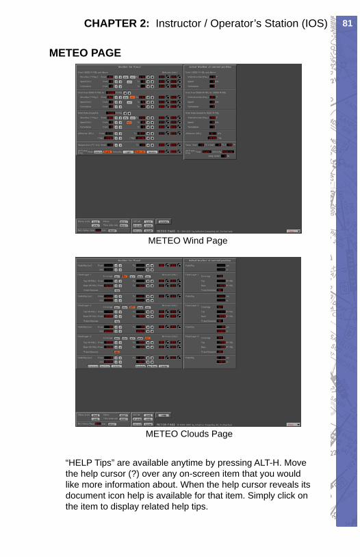
81CHAPTER 2: Instructor / Operator’s Station (IOS)
METEO PAGE
METEO Wind Page
METEO Clouds Page
“HELP Tips” are available anytime by pressing ALT-H. Move the help cursor (?) over any on-screen item that you would like more information about. When the help cursor reveals its document icon help is avail able for that item. Simply click on the item to display re lat ed help tips.
RC-1 OPERATOR’S MANUAL82
The METEO (meteorological) page is used to cre ate the weather en vi ron ment in ELITE. Pa ram e ters such as visibility, ceiling, wind, tur bu lence, pres sure and tem per a ture can be set and changed as de sired to tailor the weather to meet your specifi c train ing re quire ments.It’s advisable to practice procedures without “weath er” initially so as to gain a degree of pro fi cien cy in their execution. Then, progressively in crease the level of diffi culty by adding weather to these same procedures. One example might be to practice holding without wind at fi rst, then add winds and turbulence as you begin feeling more comfortable. This way it’s easier to vi su al ize the big picture fi rst (without wind) and grasp the essence of the procedure. After a while you’ll be shoot ing approaches to minimums and prac tic ing holds in strong winds and turbulence with out a problem.The METEO page is extremely fl exible and pro vides an opportunity for an almost infi nite amount of weath er possibilities. Please feel free to experiment.
GENERAL LAYOUT (GENVIEW)The METEO page is rather com pre hen sive and might look a bit intimidating at fi rst glance. Ac tu al ly, it is set up quite logically and is easy to use once you un der stand its layout. The METEO Page is actually two sep a rate pages, the “ CLOUDS” Page, and the “ WIND” Page. Both pages are set up in the same format left-to-right with “From” weather, “To” weather, and “Actual” weath er respectively. The CLOUDS Page is set up top-to-bottom as Layer 1 (top layer) Cloud and Visibility, Layer 2 (mid layer) Cloud and Visibility, and Layer 3 (bottom layer) Cloud and Visibility respectively. The WIND page is set up top-to-bottom as Wind (top lay er), Wind (mid layer), Wind (bottom layer), Altimeter set ting, Temperature, and Structural Icing respectively. We will examine each of these elements in greater detail in upcoming sections. To get from one page
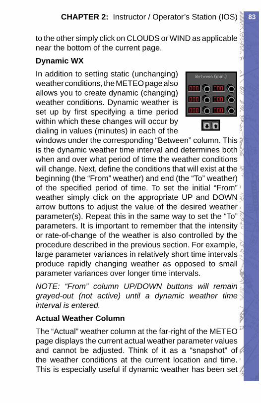
83CHAPTER 2: Instructor / Operator’s Station (IOS)
to the other simply click on CLOUDS or WIND as ap pli ca ble near the bottom of the cur rent page.Dynamic WXIn addition to setting static (unchanging) weather con di tions, the METEO page also al lows you to create dynamic (chang ing) weather con di tions. Dynamic weath er is set up by fi rst spec i fy ing a time pe ri od with in which these changes will occur by di al ing in values (min utes) in each of the windows un der the cor re spond ing “Be tween” column. This is the dy nam ic weath er time in ter val and de ter mines both when and over what period of time the weath er conditions will change. Next, de fi ne the con di tions that will exist at the be gin ning (the “From” weath er) and end (the “To” weath er) of the spec i fi ed period of time. To set the ini tial “From” weath er sim ply click on the appropriate UP and DOWN arrow but tons to adjust the value of the desired weath er parameter(s). Repeat this in the same way to set the “To” parameters. It is im por tant to re mem ber that the intensity or rate-of-change of the weath er is also con trolled by the pro ce dure de scribed in the previous sec tion. For example, large pa ram e ter variances in rel a tive ly short time in ter vals pro duce rap id ly changing weather as opposed to small parameter variances over longer time in ter vals.NOTE: “From” column UP/DOWN buttons will re main grayed-out (not active) until a dynamic weather time interval is entered.Actual Weath er Col umnThe “Actual” weather col umn at the far-right of the METEO page dis plays the current ac tu al weather pa ram e ter values and can not be ad just ed. Think of it as a “snap shot” of the weath er conditions at the cur rent lo ca tion and time. This is es pe cial ly useful if dy nam ic weath er has been set
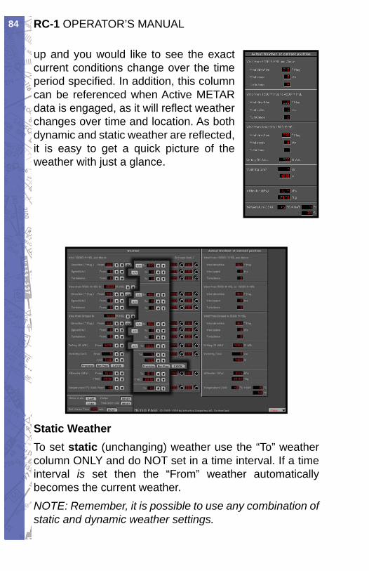
RC-1 OPERATOR’S MANUAL84
up and you would like to see the ex act current con di tions change over the time pe ri od spec i fi ed. In ad di tion, this col umn can be ref er enced when Ac tive METAR data is en gaged, as it will re fl ect weath er chang es over time and lo ca tion. As both dy nam ic and static weath er are re fl ect ed, it is easy to get a quick pic ture of the weath er with just a glance.
Stat ic Weath erTo set static (un chang ing) weather use the “To” weath er column ONLY and do NOT set in a time interval. If a time interval is set then the “From” weather au to mat i cal ly becomes the current weather.NOTE: Re mem ber, it is possible to use any com bi na tion of stat ic and dy nam ic weath er settings.
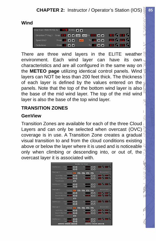
85CHAPTER 2: Instructor / Operator’s Station (IOS)
Wind
There are three wind layers in the ELITE weather en vi ron ment. Each wind layer can have its own char ac ter is tics and are all confi gured in the same way on the METEO page utilizing identical con trol panels. Wind layers can NOT be less than 200 feet thick. The thick ness of each layer is defi ned by the values entered on the panels. Note that the top of the bottom wind layer is also the base of the mid wind lay er. The top of the mid wind layer is also the base of the top wind lay er.
TRANSITION ZONESGenViewTransition Zones are available for each of the three Cloud Layers and can only be selected when overcast (OVC) coverage is in use. A Transition Zone creates a gradual visual transition to and from the cloud con di tions existing above or below the layer where it is used and is noticeable only when climbing or descending into, or out of, the overcast layer it is associated with.
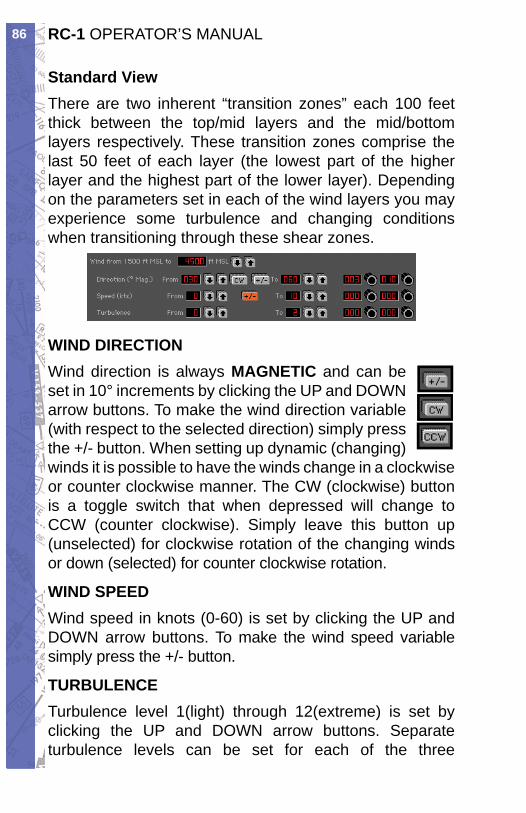
RC-1 OPERATOR’S MANUAL86
Standard ViewThere are two inherent “transition zones” each 100 feet thick between the top/mid layers and the mid/bottom layers respectively. These transition zones comprise the last 50 feet of each layer (the lowest part of the higher layer and the highest part of the lower layer). De pend ing on the parameters set in each of the wind layers you may experience some turbulence and changing conditions when transitioning through these shear zones.
WIND DIRECTIONWind direction is always MAGNETIC and can be set in 10° in cre ments by click ing the UP and DOWN ar row buttons. To make the wind di rec tion vari able (with re spect to the se lect ed di rec tion) sim ply press the +/- but ton. When set ting up dy nam ic (chang ing) winds it is pos si ble to have the winds change in a clock wise or counter clock wise man ner. The CW (clock wise) but ton is a tog gle switch that when de pressed will change to CCW (counter clock wise). Sim ply leave this but ton up (unselected) for clock wise ro ta tion of the chang ing winds or down (se lect ed) for counter clock wise ro ta tion.
WIND SPEEDWind speed in knots (0-60) is set by click ing the UP and DOWN ar row but tons. To make the wind speed variable sim ply press the +/- button.
TURBULENCETurbulence level 1(light) through 12(extreme) is set by clicking the UP and DOWN arrow buttons. Separate turbulence levels can be set for each of the three
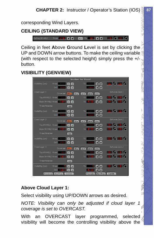
87CHAPTER 2: Instructor / Operator’s Station (IOS)
cor re spond ing Wind Layers.
CEILING (STANDARD VIEW)
Ceiling in feet Above Ground Level is set by clicking the UP and DOWN arrow buttons. To make the ceiling variable (with respect to the selected height) simply press the +/- button.
VISIBILITY (GENVIEW)
Above Cloud Layer 1:Select visibility using UP/DOWN arrows as desired. NOTE: Visibility can only be adjusted if cloud layer 1 coverage is set to OVERCAST. With an OVERCAST layer programmed, selected vis i bil i ty will become the controlling visibility above the
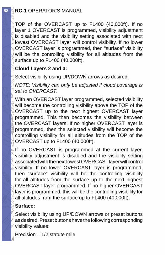
RC-1 OPERATOR’S MANUAL88
TOP of the OVERCAST up to FL400 (40,000ft). If no layer 1 OVERCAST is programmed, visibility ad just ment is disabled and the visibility setting associated with next lowest OVERCAST layer will control vis i bil i ty. If no lower OVERCAST layer is programmed, then “surface” visibility will be the controlling vis i bil i ty for all altitudes from the surface up to FL400 (40,000ft).Cloud Layers 2 and 3:Select visibility using UP/DOWN arrows as desired. NOTE: Visibility can only be adjusted if cloud cov er age is set to OVERCAST.With an OVERCAST layer programmed, selected vis i bil i ty will become the controlling visibility above the TOP of the OVERCAST up to the next highest OVER CAST layer programmed. This then becomes the vis i bil i ty between the OVERCAST layers. If no higher OVERCAST layer is programmed, then the selected visibility will become the controlling visibility for all altitudes from the TOP of the OVERCAST up to FL400 (40,000ft).If no OVERCAST is programmed at the current layer, visibility adjustment is disabled and the visibility set ting associated with the next lowest OVERCAST lay er will control visibility. If no lower OVERCAST layer is programmed, then “surface” visibility will be the con trol ling visibility for all altitudes from the surface up to the next highest OVERCAST layer programmed. If no higher OVERCAST layer is programmed, this will be the controlling visibility for all altitudes from the surface up to FL400 (40,000ft).Surface:Select visibility using UP/DOWN arrows or preset but tons as desired. Preset buttons have the following cor re spond ing visibility values:Precision = 1/2 statute mile
89CHAPTER 2: Instructor / Operator’s Station (IOS)
Non Precision = 1 statute mileCAVOK ( Ceiling/Visibility OK) = 30 statute milesNOTE: CAVOK by defi nition also indicates (in part) that no clouds or precipitation exist below 5,000ft. Press ing the CAVOK button in ELITE with Cloud Lay er 3 Base set to <= (less than or equal to) 5100ft MSL will also set cloud coverage to Sky Clear (SKC) in ad di tion to changing visibility to 30 statute miles.Preset buttons can be used to “jump” quickly to 1/2, 1, and 30 statute mile values respectively and then fur ther adjusted as desired.Visibility value selected will become the visibility from the surface up to the next highest OVERCAST (OVC) cloud layer programmed. If no OVERCAST layer is programmed, this will be the controlling visibility for all altitudes from the surface up to FL400 (40,000ft).
CLOUDS (GENVIEW)The CLOUDS Page has three Cloud/Visibility layers. Layer 1 (top), Layer 2 (mid), and Layer 3 (bottom) respectively. Select cloud coverage for each layer as de sired by press ing any one of the buttons cor re spond ing to the fol low ing :SKC Sky ClearFEW 1/8 cloud coverageSCT 2/8 to 4/8 cloud coverageBKN 5/8 to 7/8 cloud coverageOVC 8/8 cloud coverageCloud bases can also be defi ned by pressing the cor re spond ing UP/DOWN buttons. Tops can only be spec i fi ed for an overcast ( OVC) layer.
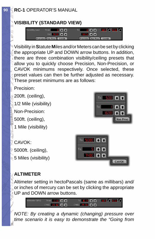
RC-1 OPERATOR’S MANUAL90
VISIBILITY (STANDARD VIEW)
Visibility in Stat ute Miles and/or Meters can be set by clicking the ap pro pri ate UP and DOWN arrow but tons. In addition, there are three combination vis i bil i ty/ceil ing presets that allow you to quickly choose Precision, Non-Precision, or CAVOK minimums respectively. Once selected, these preset values can then be further adjusted as nec es sary. These preset minimums are as follows:Precision:200ft. (ceiling),1/2 Mile (vis i bil i ty)Non-Precision:500ft. (ceiling),1 Mile (visibility)
CAVOK:5000ft. (ceiling),5 Miles (visibility)
ALTIMETERAltimeter setting in hectoPascals (same as mil li bars) and/or inches of mer cu ry can be set by clicking the appropriate UP and DOWN arrow buttons.
NOTE: By creating a dynamic (changing) pressure over time scenario it is easy to demonstrate the “Going from
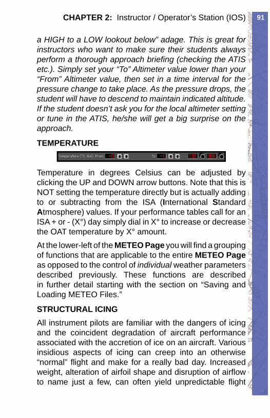
91CHAPTER 2: Instructor / Operator’s Station (IOS)
a HIGH to a LOW lookout below” adage. This is great for instructors who want to make sure their stu dents always perform a thorough ap proach briefi ng (check ing the ATIS etc.). Simply set your “To” Al tim e ter val ue low er than your “From” Altimeter value, then set in a time in ter val for the pres sure change to take place. As the pressure drops, the student will have to descend to maintain indicated al ti tude. If the student doesn’t ask you for the local al tim e ter setting or tune in the ATIS, he/she will get a big surprise on the ap proach.
TEMPERATURE
Temperature in degrees Celsius can be adjusted by click ing the UP and DOWN arrow buttons. Note that this is NOT setting the temperature di rect ly but is ac tu al ly adding to or subtracting from the ISA (In ter na tion al StandardAt mo sphere) val ues. If your per for mance tables call for an ISA + or - (X°) day sim ply dial in X° to increase or decrease the OAT tem per a ture by X° amount.At the lower-left of the METEO Page you will fi nd a grouping of func tions that are applicable to the en tire METEO Pageas opposed to the control of in di vid u al weather parameters described previously. These functions are described in further detail starting with the section on “Saving and Loading METEO Files.”
STRUCTURAL ICINGAll instrument pilots are familiar with the dangers of icing and the coincident degradation of aircraft per for mance associated with the accretion of ice on an air craft. Various insidious aspects of icing can creep into an otherwise “normal” fl ight and make for a really bad day. Increased weight, alteration of airfoil shape and disruption of airfl ow to name just a few, can often yield unpredictable fl ight
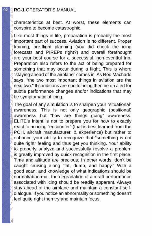
RC-1 OPERATOR’S MANUAL92
characteristics at best. At worst, these elements can conspire to become catastrophic.Like most things in life, preparation is probably the most important part of success. Aviation is no dif fer ent. Proper training, pre-fl ight planning (you did check the icing forecasts and PIREPs right?) and overall fore thought are your best course for a successful, non-event ful trip. Preparation also refers to the act of being pre pared for something that may occur during a fl ight. This is where “staying ahead of the airplane” comes in. As Rod Machado says, “the two most important things in aviation are the next two.” If conditions are ripe for icing then be on alert for subtle performance changes and/or indications that may be symptomatic of icing.The goal of any simulation is to sharpen your “sit u a tion al” awareness. This is not only geographic (po si tion al) awareness but “how are things going” aware ness. ELITE’s intent is not to prepare you for how to exactly react to an icing “encounter” (that is best learned from the POH, aircraft manufacturer, & experience) but rather to enhance your ability to recognize that “some thing is not quite right” feeling and thus get you thinking. Your ability to properly analyze and suc cess ful ly resolve a problem is greatly improved by quick recognition in the fi rst place. Time and altitude are pre cious. In other words, don’t be caught cruising along “fat, dumb, and happy.” With a good scan, and knowl edge of what indications should be normal/abnormal, the deg ra da tion of aircraft performance associated with icing should be readily apparent. Always stay ahead of the airplane and maintain a constant self-dialogue. If you notice an abnormality or something doesn’t feel quite right then try and maintain focus.
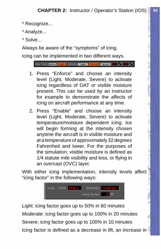
93CHAPTER 2: Instructor / Operator’s Station (IOS)
* Recognize...* Analyze...* Solve...Always be aware of the “symptoms” of icing.Icing can be implemented in two different ways.
Press “Enforce” and choose an intensity 1. level (Light, Moderate, Severe) to activate icing regardless of OAT or visible moisture present. This can be used by an in struc tor for example to demonstrate the affects of icing on aircraft performance at any time.Press “Enable” and choose an intensity 2. level (Light, Moderate, Severe) to activate temperature/moisture dependent icing. Ice will begin forming at the intensity chosen anytime the aircraft is in visible moisture and at a temperature of approximately 32 degrees Fahr en heit and lower. For the purposes of the simulation, vis i ble moisture is defi ned as 1/4 statute mile visibility and less, or fl ying in an overcast (OVC) layer.
With either icing implementation, intensity levels af fect “ic ing factor” in the fol low ing ways:
Light: icing factor goes up to 50% in 60 minutesModerate: icing factor goes up to 100% in 20 minutesSevere: icing factor goes up to 100% in 10 minutesIcing factor is defi ned as a decrease in lift, an increase in
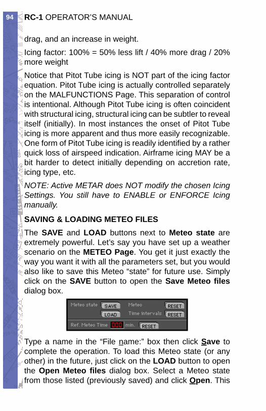
RC-1 OPERATOR’S MANUAL94
drag, and an increase in weight.Icing factor: 100% = 50% less lift / 40% more drag / 20% more weightNotice that Pitot Tube icing is NOT part of the icing factor equation. Pitot Tube icing is actually controlled separately on the MALFUNCTIONS Page. This sep a ra tion of control is intentional. Although Pitot Tube ic ing is often coincident with structural icing, structural icing can be subtler to reveal itself (initially). In most instances the onset of Pitot Tube icing is more ap par ent and thus more easily recognizable. One form of Pitot Tube icing is readily identifi ed by a rather quick loss of airspeed in di ca tion. Airframe icing MAY be a bit harder to detect initially depending on accretion rate, icing type, etc.NOTE: Active METAR does NOT modify the chosen Icing Settings. You still have to ENABLE or EN FORCE Icing manually.
SAVING & LOADING METEO FILESThe SAVE and LOAD buttons next to Meteo state are ex treme ly pow er ful. Let’s say you have set up a weath er sce nar io on the METEO Page. You get it just exactly the way you want it with all the pa ram e ters set, but you would also like to save this Meteo “state” for fu ture use. Sim ply click on the SAVE but ton to open the Save Meteo fi lesdialog box.
Type a name in the “File name:” box then click Save to com plete the op er a tion. To load this Meteo state (or any other) in the fu ture, just click on the LOAD button to open the Open Meteo fi les di a log box. Se lect a Meteo state from those list ed (pre vi ous ly saved) and click Open. This
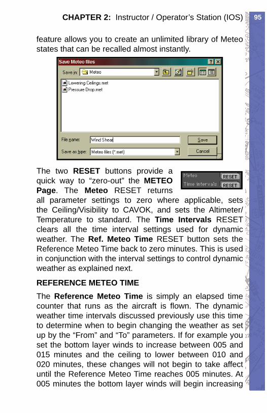
95CHAPTER 2: Instructor / Operator’s Station (IOS)
fea ture al lows you to cre ate an un lim it ed library of Meteo states that can be re called al most instantly.
The two RESET buttons pro vide a quick way to “zero-out” the METEO Page. The Meteo RESET returns all pa ram e ter settings to zero where ap pli ca ble, sets the Ceiling/Vis i bil i ty to CAVOK, and sets the Al tim e ter/Tem per a ture to stan dard. The Time In ter vals RE SET clears all the time interval set tings used for dy nam ic weath er. The Ref. Meteo Time RESET but ton sets the Ref er ence Meteo Time back to zero min utes. This is used in con junc tion with the in ter val set tings to control dynamic weather as ex plained next.
REFERENCE METEO TIMEThe Reference Meteo Time is simply an elapsed time counter that runs as the aircraft is fl own. The dy nam ic weather time in ter vals discussed pre vi ous ly use this time to determine when to begin changing the weath er as set up by the “From” and “To” parameters. If for example you set the bot tom layer winds to increase between 005 and 015 minutes and the ceiling to lower be tween 010 and 020 minutes, these chang es will not begin to take af fect until the Reference Meteo Time reaches 005 min utes. At 005 minutes the bottom layer winds will be gin increasing
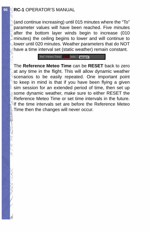
RC-1 OPERATOR’S MANUAL96
(and continue increasing) until 015 min utes where the “To” pa ram e ter val ues will have been reached. Five minutes after the bottom lay er winds begin to increase (010 min utes) the ceiling be gins to lower and will con tin ue to lower until 020 min utes. Weather parameters that do NOT have a time in ter val set (static weath er) remain constant.
The Reference Meteo Time can be RESET back to zero at any time in the fl ight. This will allow dynamic weather scenarios to be easily re peat ed. One im por tant point to keep in mind is that if you have been fl ying a given sim session for an ex tend ed period of time, then set up some dy nam ic weather, make sure to ei ther RE SET the Ref er ence Meteo Time or set time in ter vals in the future. If the time intervals set are before the Ref er ence Meteo Time then the changes will nev er occur.
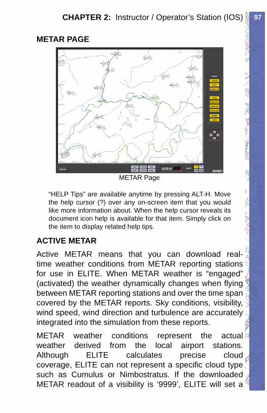
97CHAPTER 2: Instructor / Operator’s Station (IOS)
METAR PAGE
METAR Page
“HELP Tips” are available anytime by pressing ALT-H. Move the help cursor (?) over any on-screen item that you would like more information about. When the help cursor reveals its document icon help is avail able for that item. Simply click on the item to display re lat ed help tips.
ACTIVE METARActive METAR means that you can download real-time weather conditions from METAR reporting stations for use in ELITE. When METAR weather is “en gaged” (activated) the weather dynamically changes when fl ying between METAR reporting stations and over the time span covered by the METAR reports. Sky conditions, visibility, wind speed, wind direction and turbulence are accurately integrated into the simulation from these reports.METAR weather conditions represent the actual weath er derived from the local airport stations. Al though ELITE calculates precise cloud coverage, ELITE can not represent a specifi c cloud type such as Cumulus or Nimbostratus. If the downloaded METAR readout of a visibility is ‘9999’, ELITE will set a

RC-1 OPERATOR’S MANUAL98
value between 10 km and 30 km, otherwise it will take the reported value such as i.e. 24 km or 15 sm.
WIND AND GUSTSELITE calculates the weather between the METAR conditions received by the Aircraft. If the wind is 270° and the next available METAR station reads 260°, ELITE will constantly update the wind from 270° to 269, 268, 267 etc. until reaching 260°. The same ap pears for all other values such as wind speed, cloud coverage, temperature, dew point, visibility and QNH/ALT. The symbols used in the METAR page are ICAO standard. When gusts are reported, ELITE will set the appropriate wind speed and turbulence to level 2 for a short period.
USING THE METAR PAGEOpen the METAR page through the menu bar in the lower right corner or type ‘alt & R’ on your keyboard.NOTE: Active METAR is only available with GenView™ vi su al databases.Once in the METAR page, you have the choice of se lect ing existing METAR conditions which have been previously downloaded from the Internet or you can download current METAR conditions online through the use of the D-LOADfunc tion.
USING EXISTING METAR DATAPress the 1. LOAD button on the METAR page to open existing METAR fi les previously saved to your hard drive.
From the directory list select the METAR 2. fi le. (i.e. 05Z.TXT) 05Z means zulu time, 434.5Kb is the size of the fi le and May 29
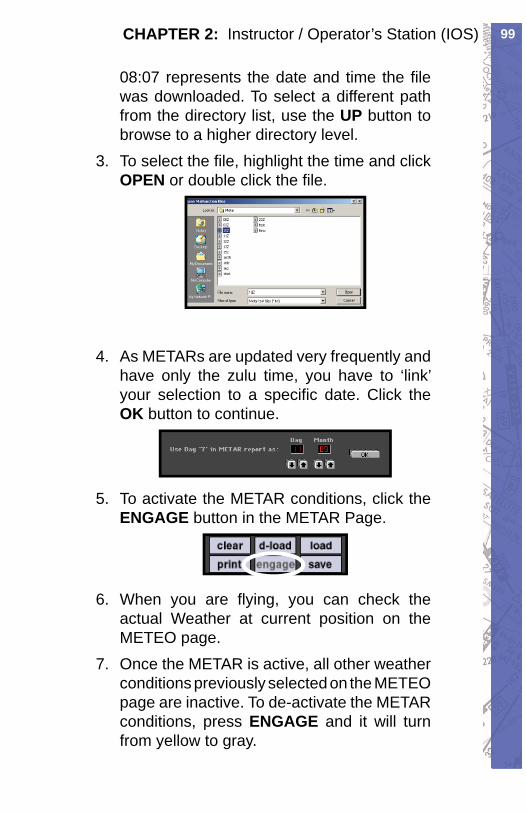
99CHAPTER 2: Instructor / Operator’s Station (IOS)
08:07 represents the date and time the fi le was down load ed. To se lect a dif fer ent path from the di rec to ry list, use the UP but ton to browse to a higher directory level.To se lect the fi le, highlight the time and click 3. OPEN or dou ble click the fi le.
As METARs are updated very frequently and 4. have only the zulu time, you have to ‘link’ your selection to a specifi c date. Click the OK button to continue.
To activate the METAR conditions, click the 5. EN GAGE button in the METAR Page.
When you are fl ying, you can check the 6. actual Weath er at current position on the METEO page.Once the METAR is active, all other weather 7. con di tions previously selected on the METEO page are inactive. To de-activate the METAR con di tions, press ENGAGE and it will turn from yellow to gray.
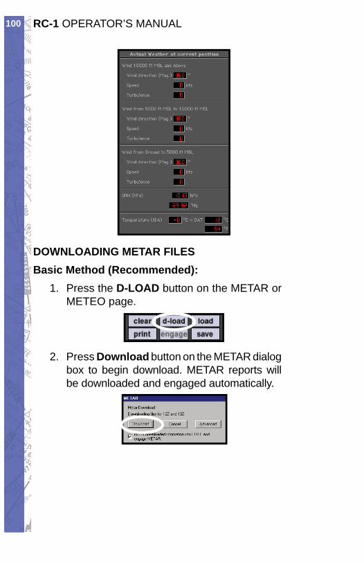
RC-1 OPERATOR’S MANUAL100
DOWNLOADING METAR FILESBasic Method (Recommended):
Press the 1. D-LOAD button on the METAR or ME TEO page.
Press 2. Download button on the METAR dialog box to begin download. METAR reports will be down load ed and engaged automatically.
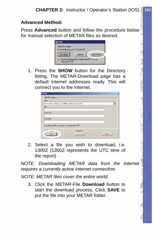
101CHAPTER 2: Instructor / Operator’s Station (IOS)
Advanced Method:Press Advanced button and follow the procedure be low for manual selection of METAR fi les as de sired.
Press the 1. SHOW button for the Directory list ing. The METAR-Download page has a default internet addresses ready. This will connect you to the Internet.
Select a fi le you wish to download, i.e. 2. 1300Z (1300Z represents the UTC time of the report)
NOTE: Downloading METAR data from the Internet re quires a currently active Internet connection. NOTE: METAR fi les cover the entire world.
Click the METAR-File 3. Download button to start the download process. Click SAVE to put the fi le into your METAR folder.
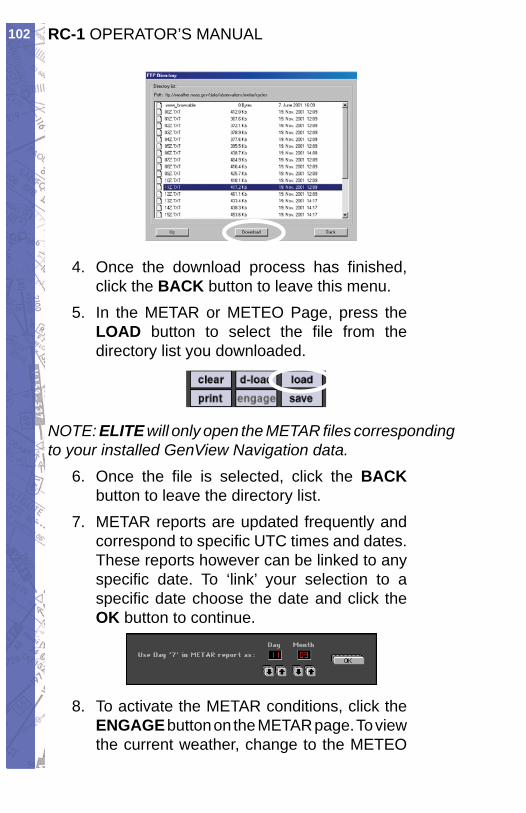
RC-1 OPERATOR’S MANUAL102
Once the download process has fi nished, 4. click the BACK button to leave this menu.In the METAR or METEO Page, press the 5. LOAD button to select the fi le from the directory list you downloaded.
NOTE: ELITE will only open the METAR fi les corresponding to your installed GenView Navigation data.
Once the fi le is selected, click the 6. BACKbutton to leave the directory list.METAR reports are updated frequently and 7. cor re spond to specifi c UTC times and dates. These re ports however can be linked to any specifi c date. To ‘link’ your selection to a specifi c date choose the date and click the OK button to continue.
To activate the METAR conditions, click the 8. EN GAGE button on the METAR page. To view the current weather, change to the METEO
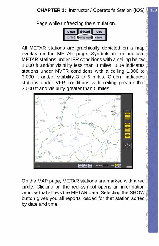
103CHAPTER 2: Instructor / Operator’s Station (IOS)
Page while unfreezing the simulation.
All METAR stations are graphically depicted on a map overlay on the METAR page. Symbols in red indicate METAR stations under IFR conditions with a ceiling below 1,000 ft and/or visibility less than 3 miles. Blue indicates stations under MVFR conditions with a ceil ing 1,000 to 3,000 ft and/or visibility 3 to 5 miles. Green indicates stations under VFR conditions with ceiling greater that 3,000 ft and visibility greater than 5 miles.
On the MAP page, METAR stations are marked with a red circle. Clicking on the red symbol opens an in for ma tion window that shows the METAR data. Se lect ing the SHOW button gives you all reports loaded for that station sorted by date and time.
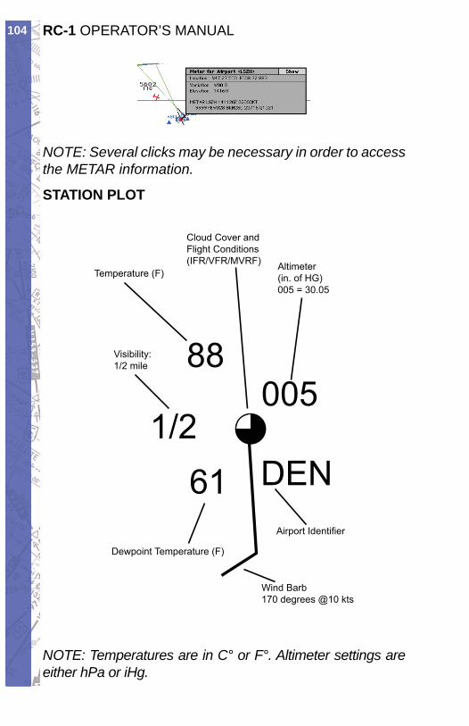
RC-1 OPERATOR’S MANUAL104
NOTE: Several clicks may be necessary in order to access the METAR information.
STATION PLOT
Temperature (F)
Cloud Cover andFlight Conditions(IFR/VFR/MVRF) Altimeter
(in. of HG)005 = 30.05
Airport Identifier
Wind Barb170 degrees @10 kts
Visibility:1/2 mile
Dewpoint Temperature (F)
88005
DEN611/2
NOTE: Temperatures are in C° or F°. Altimeter set tings are either hPa or iHg.
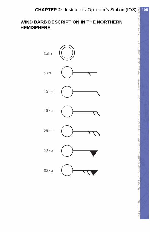
105CHAPTER 2: Instructor / Operator’s Station (IOS)
WIND BARB DESCRIPTION IN THE NORTHERN HEMISPHERE
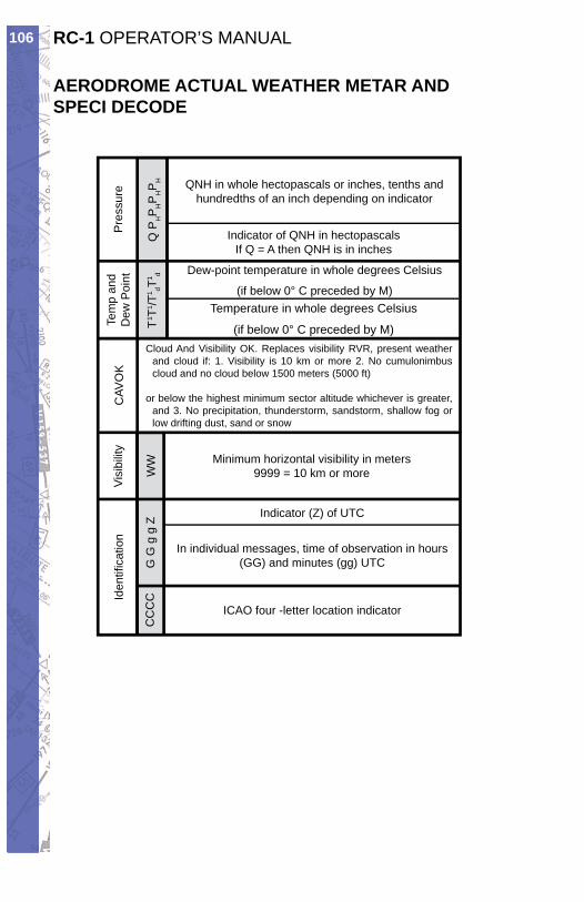
RC-1 OPERATOR’S MANUAL106
AERODROME ACTUAL WEATHER METAR AND SPECI DECODE
Iden
tifi c
atio
n
CC
CC
GG
gg
Z
ICAO four -letter location indicator
In individual messages, time of observation in hours (GG) and minutes (gg) UTC
Indicator (Z) of UTC
Visi
bilit
y
WW Minimum horizontal visibility in meters
9999 = 10 km or more
CAV
OK
Cloud And Visibility OK. Replaces visibility RVR, present weather and cloud if: 1. Visibility is 10 km or more 2. No cumulonimbus cloud and no cloud below 1500 meters (5000 ft)
or below the highest minimum sector altitude whichever is greater, and 3. No precipitation, thunderstorm, sandstorm, shallow fog or low drifting dust, sand or snow
Temperature in whole degrees Celsius
(if below 0° C preceded by M)Tem
p an
d D
ew P
oint
T1 T
1 /T1 dT
1 d Dew-point temperature in whole degrees Celsius
(if below 0° C preceded by M)
Pre
ssur
e
Q P
HP
HP
HP
H
Indicator of QNH in hectopascalsIf Q = A then QNH is in inches
QNH in whole hectopascals or inches, tenths andhundredths of an inch depending on indicator
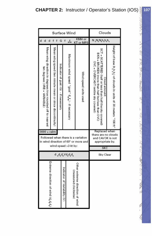
107CHAPTER 2: Instructor / Operator’s Station (IOS)
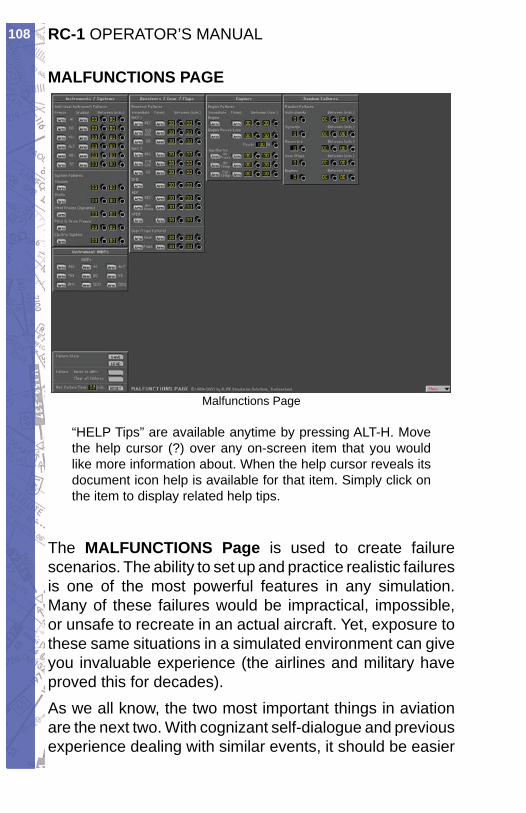
RC-1 OPERATOR’S MANUAL108
MALFUNCTIONS PAGE
Malfunctions Page
“HELP Tips” are available anytime by pressing ALT-H. Move the help cursor (?) over any on-screen item that you would like more information about. When the help cursor reveals its document icon help is avail able for that item. Simply click on the item to display re lat ed help tips.
The MALFUNCTIONS Page is used to cre ate fail ure scenarios. The abil i ty to set up and prac tice realistic failures is one of the most pow er ful fea tures in any simulation. Many of these failures would be im prac ti cal, impossible, or unsafe to rec re ate in an actual air craft. Yet, exposure to these same situations in a sim u lat ed environment can give you invaluable experience (the airlines and military have proved this for de cades).As we all know, the two most im por tant things in aviation are the next two. With cognizant self-di a logue and previous experience deal ing with sim i lar events, it should be easier
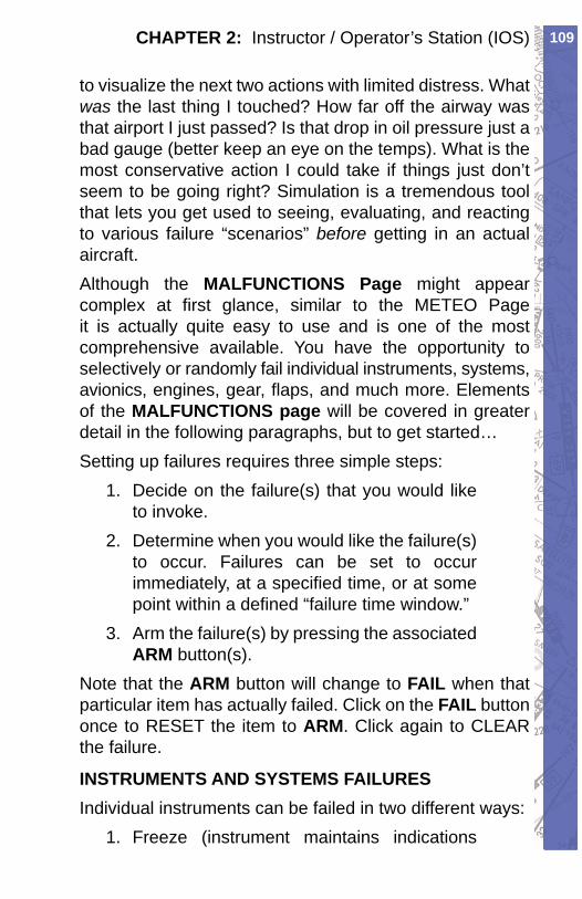
109CHAPTER 2: Instructor / Operator’s Station (IOS)
to vi su al ize the next two ac tions with limited dis tress. What was the last thing I touched? How far off the airway was that airport I just passed? Is that drop in oil pres sure just a bad gauge (better keep an eye on the temps). What is the most con ser va tive action I could take if things just don’t seem to be going right? Simulation is a tremendous tool that lets you get used to see ing, evaluating, and reacting to various failure “sce nar i os” before getting in an actual aircraft. Although the MALFUNCTIONS Page might ap pear complex at fi rst glance, similar to the METEO Page it is actually quite easy to use and is one of the most comprehensive available. You have the opportunity to se lec tive ly or randomly fail individual in stru ments, systems, avionics, engines, gear, fl aps, and much more. Elements of the MAL FUNC TIONS page will be cov ered in great er detail in the following paragraphs, but to get started…Setting up failures requires three simple steps:
Decide on the failure(s) that you would like 1. to in voke.Determine when you would like the failure(s) 2. to occur. Failures can be set to occur im me di ate ly, at a specifi ed time, or at some point with in a defi ned “fail ure time window.”Arm the failure(s) by press ing the as so ci at ed 3. ARM button(s).
Note that the ARM button will change to FAIL when that par tic u lar item has ac tu al ly failed. Click on the FAIL button once to RESET the item to ARM. Click again to CLEAR the failure.
INSTRUMENTS AND SYSTEMS FAIL URESIndividual in stru ments can be failed in two dif fer ent ways:
Freeze (in stru ment main tains in di ca tions 1.
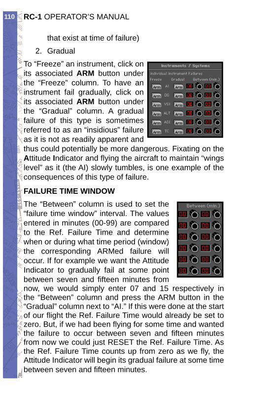
RC-1 OPERATOR’S MANUAL110
that ex ist at time of fail ure)Gradual2.
To “Freeze” an in stru ment, click on its as so ci at ed ARM but ton under the “Freeze” col umn. To have an in stru ment fail grad u al ly, click on its as so ci at ed ARM but ton un der the “Grad u al” col umn. A gradual fail ure of this type is some times re ferred to as an “in sid i ous” fail ure as it is not as readily apparent and thus could po ten tial ly be more dan ger ous. Fix at ing on the At ti tude In di ca tor and fl y ing the aircraft to maintain “wings lev el” as it (the AI) slowly tumbles, is one example of the con se quenc es of this type of failure.
FAILURE TIME WIN DOWThe “Be tween” col umn is used to set the “failure time win dow” in ter val. The val ues en tered in min utes (00-99) are com pared to the Ref. Fail ure Time and de ter mine when or during what time pe ri od (win dow) the cor re spond ing ARMed fail ure will oc cur. If for ex am ple we want the At ti tude Indicator to grad u al ly fail at some point be tween sev en and fi f teen minutes from now, we would sim ply en ter 07 and 15 re spec tive ly in the “Be tween” col umn and press the ARM button in the “Grad u al” column next to “AI.” If this were done at the start of our fl ight the Ref. Fail ure Time would al ready be set to zero. But, if we had been fl y ing for some time and want ed the failure to occur be tween sev en and fi f teen min utes from now we could just RE SET the Ref. Fail ure Time. As the Ref. Failure Time counts up from zero as we fl y, the At ti tude In di ca tor will be gin its grad u al failure at some time be tween sev en and fi f teen min utes.
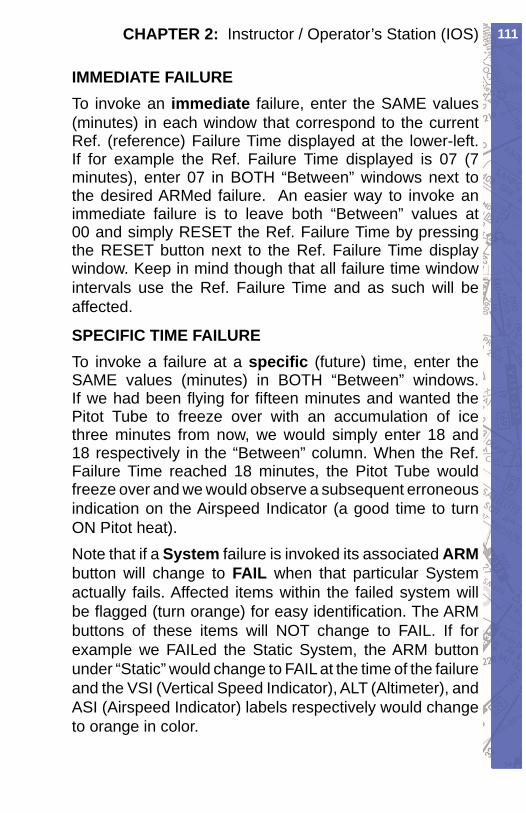
111CHAPTER 2: Instructor / Operator’s Station (IOS)
IMMEDIATE FAILURETo invoke an im me di ate failure, enter the SAME val ues (minutes) in each window that cor re spond to the current Ref. (reference) Failure Time dis played at the lower-left. If for example the Ref. Failure Time dis played is 07 (7 min utes), enter 07 in BOTH “Be tween” windows next to the desired ARMed fail ure. An easier way to invoke an immediate failure is to leave both “Be tween” values at 00 and simply RESET the Ref. Failure Time by pressing the RE SET button next to the Ref. Failure Time display window. Keep in mind though that all failure time window in ter vals use the Ref. Fail ure Time and as such will be affected.
SPECIFIC TIME FAILURETo invoke a fail ure at a specifi c (future) time, en ter the SAME values (min utes) in BOTH “Be tween” win dows. If we had been fl ying for fi f teen min utes and wanted the Pitot Tube to freeze over with an accumulation of ice three minutes from now, we would simply enter 18 and 18 re spec tive ly in the “Between” column. When the Ref. Failure Time reached 18 minutes, the Pi tot Tube would freeze over and we would observe a subsequent er ro ne ous in di ca tion on the Airspeed In di ca tor (a good time to turn ON Pitot heat).Note that if a System failure is invoked its as so ci at ed ARMbutton will change to FAIL when that particular System actually fails. Affected items within the failed system will be fl agged (turn or ange) for easy iden ti fi ca tion. The ARM buttons of these items will NOT change to FAIL. If for ex am ple we FAILed the Static Sys tem, the ARM but ton under “Static” would change to FAIL at the time of the failure and the VSI (Vertical Speed In di ca tor), ALT (Al tim e ter), and ASI (Airspeed In di ca tor) labels respectively would change to or ange in color.
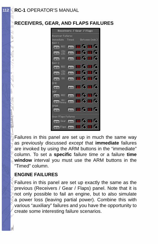
RC-1 OPERATOR’S MANUAL112
RECEIVERS, GEAR, AND FLAPS FAILURES
Failures in this pan el are set up in much the same way as pre vi ous ly discussed except that im me di ate failures are invoked by us ing the ARM but tons in the “im me di ate” column. To set a specifi c failure time or a failure time window interval you must use the ARM buttons in the “Timed” col umn.
ENGINE FAILURESFailures in this pan el are set up exactly the same as the previous (Re ceiv ers / Gear / Flaps) panel. Note that it is not only possible to fail an engine, but to also sim u late a power loss (leaving partial power). Combine this with var i ous “auxiliary” failures and you have the op por tu ni ty to create some interesting failure sce nar i os.
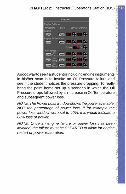
113CHAPTER 2: Instructor / Operator’s Station (IOS)
A good way to see if a student is including engine in stru ments in his/her scan is to invoke an Oil Pressure failure and see if the student notices the pres sure drop ping. To really bring the point home set up a scenario in which the Oil Pressure drops fol lowed by an increase in Oil Tem per a ture and sub se quent power loss.NOTE: The Power Loss window shows the pow er avail able, NOT the per cent age of power loss. If for ex am ple the power loss win dow were set to 40%, this would indicate a 60% loss of pow er.NOTE: Once an engine failure or power loss has been in voked, the failure must be CLEARED to allow for engine restart or power restoration.
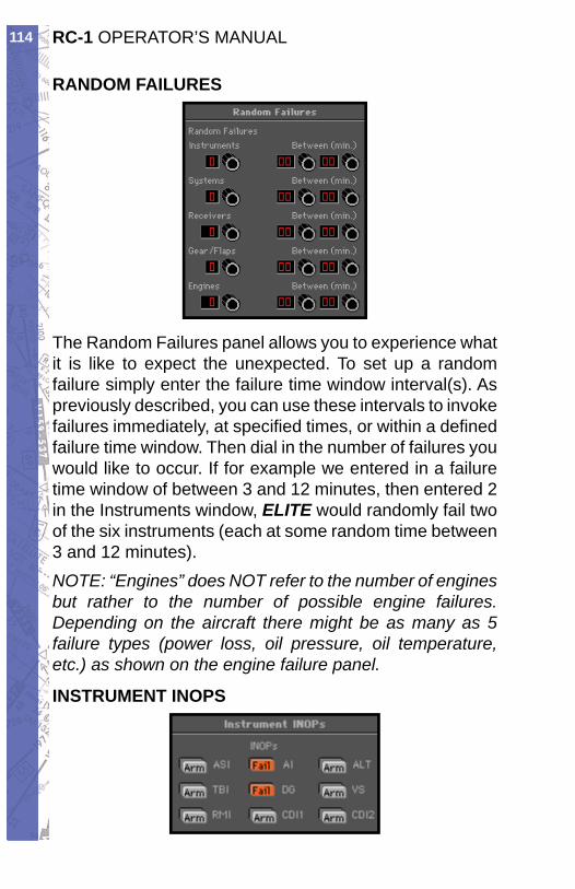
RC-1 OPERATOR’S MANUAL114
RANDOM FAILURES
The Random Fail ures panel allows you to ex pe ri ence what it is like to expect the unexpected. To set up a random failure sim ply enter the failure time win dow interval(s). As pre vi ous ly de scribed, you can use these intervals to in voke failures im me di ate ly, at specifi ed times, or within a defi ned failure time window. Then dial in the number of failures you would like to occur. If for example we entered in a failure time window of between 3 and 12 minutes, then entered 2 in the In stru ments window, ELITE would randomly fail two of the six instruments (each at some random time be tween 3 and 12 min utes).NOTE: “Engines” does NOT refer to the num ber of en gines but rather to the number of pos si ble engine failures. Depending on the aircraft there might be as many as 5 failure types (power loss, oil pressure, oil tem per a ture, etc.) as shown on the engine failure pan el.
INSTRUMENT INOPS
115CHAPTER 2: Instructor / Operator’s Station (IOS)
The Instrument INOP feature allows you to place a virtual instrument cover on a selected instrument or instruments. The covers are similar in appearance to the rubber suction cup covers used in instrument training for partial panel practice. The covers can be used independent of, or in conjunction with, specifi c malfunctions as follows: Invoke a malfunction by itself (without the cover). Cover the instrument (without invoking a malfunction). Invoke a malfunction AND cover the instrument.The third option allows the instructor to cover an instrument at his discretion once he is comfortable that the student has recognized and acknowledged the failure.To place an instrument cover on one or more instruments, simply click on the desired instrument’s ARM button. The button will turn orange and subsequently display “Fail” to indicate the instrument has been covered. Note that the Instrument INOP feature is activated almost immediately after ARM has been pressed. The Instrument INOP feature is therefore not “timed” nor does its use depend on the Ref. Failure Time. The graphic above shows that the attitude indicator and directional gyro have been selected and have INOP covers on them. At the lower-left of the MALFUNCTIONS page you will fi nd several buttons that are ap pli ca ble to the entire MALFUNCTIONS page as op posed to the control of individual fail ures described previously.
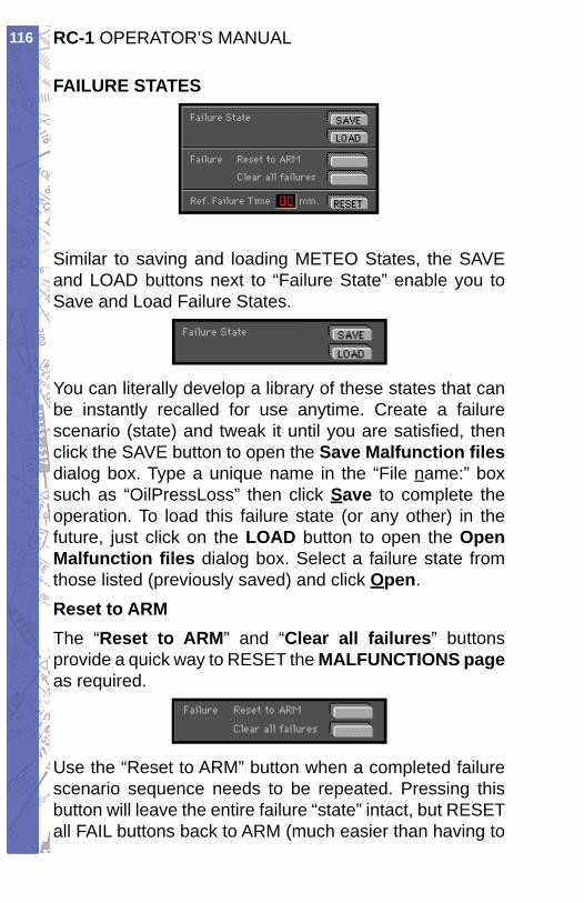
RC-1 OPERATOR’S MANUAL116
FAILURE STATES
Similar to saving and loading METEO States, the SAVE and LOAD but tons next to “Failure State” enable you to Save and Load Failure States.
You can literally de vel op a library of these states that can be instantly re called for use anytime. Create a failure scenario (state) and tweak it until you are satisfi ed, then click the SAVE button to open the Save Malfunction fi lesdialog box. Type a unique name in the “File name:” box such as “OilPressLoss” then click Save to complete the op er a tion. To load this failure state (or any other) in the fu ture, just click on the LOAD button to open the Open Malfunction fi les dialog box. Se lect a failure state from those listed (previously saved) and click Open.Reset to ARMThe “ Reset to ARM” and “ Clear all failures” but tons provide a quick way to RESET the MAL FUNC TIONS pageas re quired.
Use the “Reset to ARM” button when a com plet ed fail ure scenario sequence needs to be repeated. Pressing this button will leave the entire failure “state” intact, but RESET all FAIL buttons back to ARM (much eas i er than having to
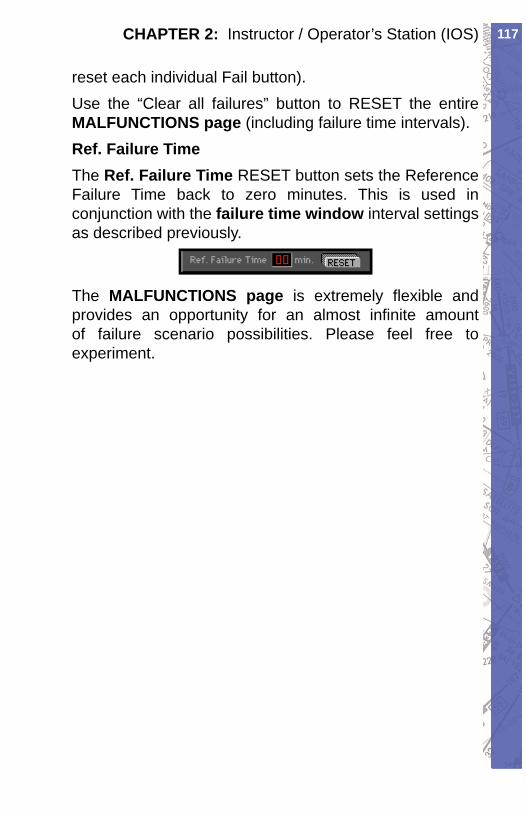
117CHAPTER 2: Instructor / Operator’s Station (IOS)
reset each in di vid u al Fail button).Use the “Clear all failures” button to RESET the entire MAL FUNC TIONS page (including failure time in ter vals).Ref. Failure TimeThe Ref. Failure Time RESET button sets the Ref er ence Failure Time back to zero minutes. This is used in conjunction with the failure time window interval set tings as described previously.
The MALFUNCTIONS page is extremely fl exible and provides an op por tu ni ty for an almost in fi nite amount of failure scenario possibilities. Please feel free to ex per i ment.
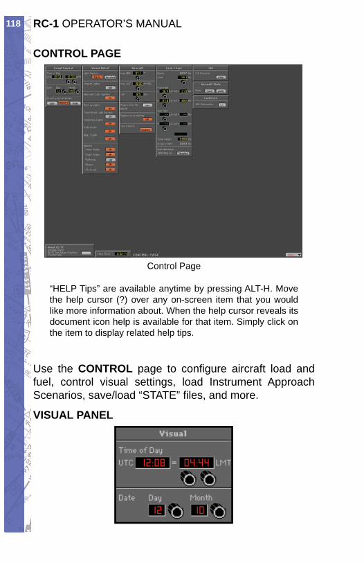
RC-1 OPERATOR’S MANUAL118
CONTROL PAGE
Control Page
“HELP Tips” are available anytime by pressing ALT-H. Move the help cursor (?) over any on-screen item that you would like more information about. When the help cursor reveals its document icon help is available for that item. Simply click on the item to display re lat ed help tips.
Use the CONTROL page to con fi g ure air craft load and fuel, control visual settings, load Instrument Approach Sce nar i os, save/load “STATE” fi les, and more.
VISUAL PANEL
119CHAPTER 2: Instructor / Operator’s Station (IOS)
Use the Visual panel to confi gure ELITE’s visual dis play set tings. Everything from Time-of-Day to the amount of runway environment detail displayed can be changed.Set Date and Time:Set the Time of Day and Date. Daylight is accurately re fl ect ed based upon navigation data load ed and time set.At program start, ELITE references your com put er’s internal clock, then applies the (LT)/(UTC) offset from the General settings dialog box on the Confi guration. The calculated current UTC (Uni ver sal Time Co or di nat ed) time is then used for all cock pit clocks and appears on the Time of Day pan el in the UTC win dow. The time dis played in the LMT (Lo cal Mean Time) window will probably NOT re fl ect the current local watch time of the area fl own in. THIS IS NOR MAL! LMT is used to calculate accurate sun rise and sunset times. Depending on aircraft location within the specifi c Time Zone fl own in, and Daylight Sav ing Time, LMT may be “off” by as much as 2 Hrs. Use this time only as a reference for set ting day/night fl y ing con di tions. To change time of day, click and drag on hours/min utes adjust knobs located below LMT dis play window.
PRESET LEVEL OF DETAIL (GENVIEW)Software “performance” is directly related to the com put er hardware and associated capabilities used to run it. Many factors such as processor speed, memory, vid eo card and drivers, come together to formulate what the end user per ceives as com put er “power.” Some per for mance gain may be achieved however through the soft ware by fi ne-tuning Gen View’s visual settings.Based on the processing power of your computer, you may want to adjust the Level of Detail (LOD) setting by pressing one of the LOW, MEDIUM, or HIGH but tons.
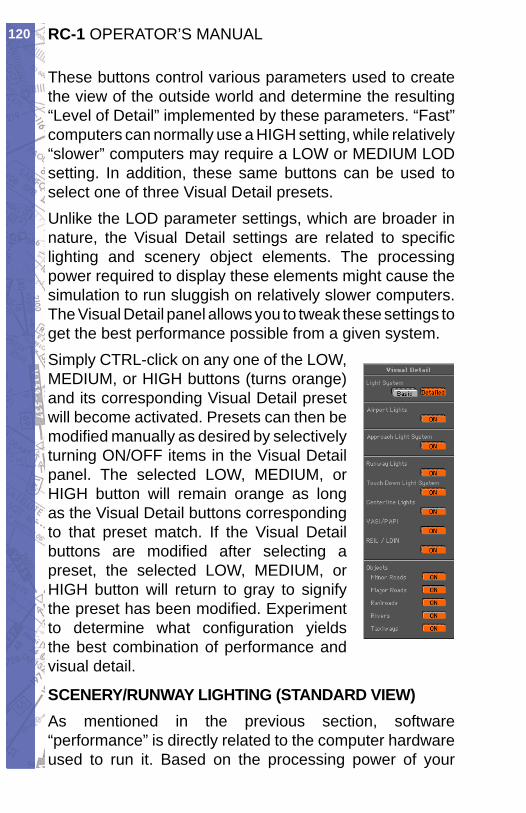
RC-1 OPERATOR’S MANUAL120
These buttons control var i ous pa ram e ters used to create the view of the outside world and determine the re sult ing “Level of Detail” im ple ment ed by these pa ram e ters. “Fast” computers can nor mal ly use a HIGH setting, while rel a tive ly “slow er” com put ers may re quire a LOW or ME DI UM LOD set ting. In addition, these same but tons can be used to select one of three Visual De tail presets.Unlike the LOD parameter settings, which are broader in nature, the Visual Detail settings are related to spe cifi c light ing and scenery object el e ments. The pro cess ing power required to display these elements might cause the simulation to run sluggish on relatively slow er computers. The Visual Detail panel allows you to tweak these settings to get the best per for mance possible from a given system. Simply CTRL-click on any one of the LOW, ME DI UM, or HIGH but tons (turns orange) and its cor re spond ing Visual Detail pre set will become ac ti vat ed. Presets can then be mod i fi ed manually as de sired by se lec tive ly turning ON/OFF items in the Visual Detail panel. The se lect ed LOW, ME DI UM, or HIGH button will re main orange as long as the Visual Detail buttons cor re spond ing to that preset match. If the Vi su al Detail buttons are modifi ed af ter se lect ing a preset, the selected LOW, ME DI UM, or HIGH button will re turn to gray to signify the pre set has been modifi ed. Ex per i ment to de ter mine what con fi g u ra tion yields the best combination of per for mance and vi su al detail.
SCENERY/RUNWAY LIGHT ING (STAN DARD VIEW)As mentioned in the previous sec tion, software “per for mance” is directly related to the computer hardware used to run it. Based on the pro cess ing power of your
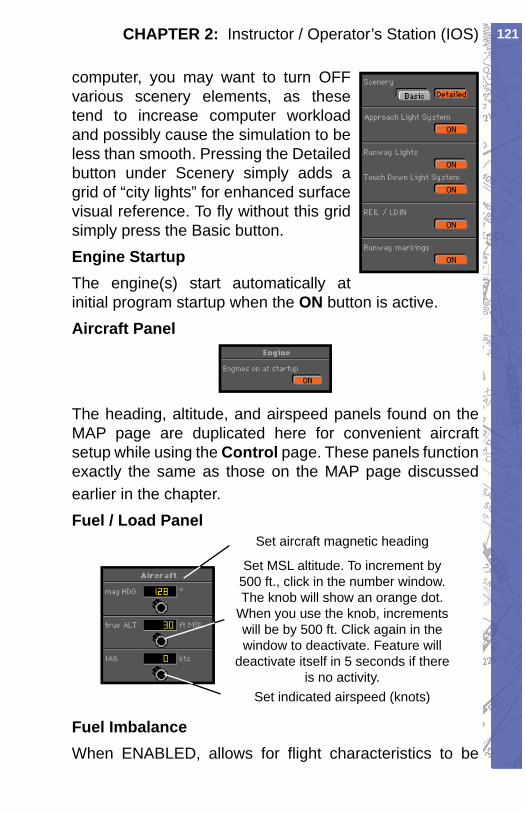
121CHAPTER 2: Instructor / Operator’s Station (IOS)
com put er, you may want to turn OFF various scenery elements, as these tend to increase com put er workload and possibly cause the simulation to be less than smooth. Pressing the De tailed button un der Scenery simply adds a grid of “city lights” for en hanced sur face visual ref er ence. To fl y without this grid simply press the Basic button.Engine StartupThe engine(s) start automatically at initial program startup when the ON button is active.Aircraft Panel
The heading, altitude, and air speed panels found on the MAP page are duplicated here for convenient air craft setup while using the Con trol page. These pan els func tion exactly the same as those on the MAP page discussed earlier in the chapter.Fuel / Load Panel
Set aircraft magnetic heading
Set indicated airspeed (knots)
Set MSL altitude. To increment by 500 ft., click in the number window. The knob will show an orange dot.
When you use the knob, increments will be by 500 ft. Click again in the window to deactivate. Feature will
deactivate itself in 5 seconds if there is no activity.
Fuel ImbalanceWhen ENABLED, allows for fl ight characteristics to be
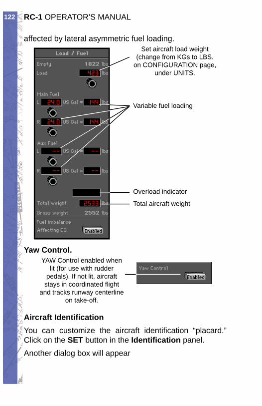
RC-1 OPERATOR’S MANUAL122
affected by lateral asymmetric fuel loading.Set aircraft load weight
(change from KGs to LBS. on CONFIGURATION page,
under UNITS.
Variable fuel loading
Overload indicator
Total aircraft weight
Yaw Control.YAW Control enabled when
lit (for use with rudderpedals). If not lit, aircraft
stays in coordinated fl ight and tracks runway centerline
on take-off.
Aircraft Identifi cationYou can customize the aircraft iden ti fi ca tion “plac ard.” Click on the SET button in the Iden ti fi ca tion pan el.Another dialog box will appear
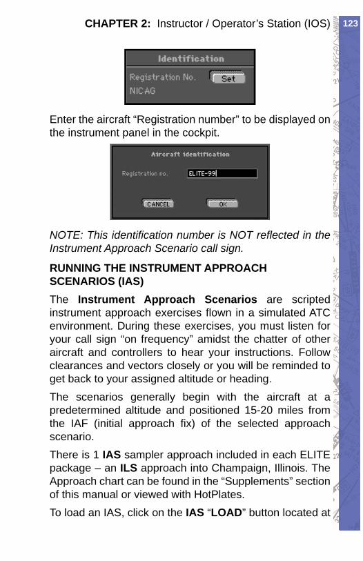
123CHAPTER 2: Instructor / Operator’s Station (IOS)
Enter the aircraft “Registration number” to be dis played on the instrument panel in the cock pit.
NOTE: This identifi cation number is NOT re fl ect ed in the Instrument Approach Sce nar io call sign.
RUNNING THE INSTRUMENT APPROACH SCENARIOS (IAS)The Instrument Approach Scenarios are script ed in stru ment approach exercises fl own in a sim u lat ed ATC environment. During these ex er cis es, you must lis ten for your call sign “on fre quen cy” amidst the chatter of oth er aircraft and con trol lers to hear your in struc tions. Follow clear anc es and vectors closely or you will be re mind ed to get back to your assigned al ti tude or head ing.The scenarios gen er al ly begin with the air craft at a pre de ter mined altitude and positioned 15-20 miles from the IAF (ini tial ap proach fi x) of the se lect ed approach scenario.There is 1 IAS sampler ap proach in clud ed in each ELITE package – an ILS ap proach into Champaign, Illinois. The Approach chart can be found in the “Supplements” section of this manual or viewed with HotPlates.To load an IAS, click on the IAS “LOAD” button located at
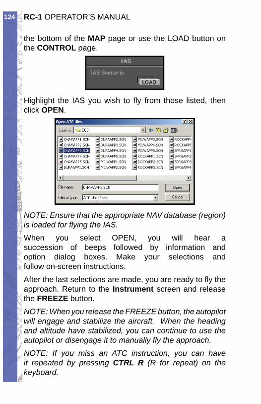
RC-1 OPERATOR’S MANUAL124
the bottom of the MAP page or use the LOAD button on the CON TROL page.
Highlight the IAS you wish to fl y from those listed, then click OPEN.
NOTE: Ensure that the appropriate NAV database (region) is load ed for fl ying the IAS. When you select OPEN, you will hear a suc ces sion of beeps followed by information and op tion dialog box es. Make your se lec tions and fol low on-screen in struc tions. After the last selections are made, you are ready to fl y the approach. Return to the Instrument screen and re lease the FREEZE button.NOTE: When you release the FREEZE button, the au to pi lot will engage and stabilize the air craft. When the heading and altitude have stabilized, you can continue to use the au to pi lot or dis en gage it to man u al ly fl y the approach.NOTE: If you miss an ATC in struc tion, you can have it repeated by pressing CTRL R (R for repeat) on the keyboard.
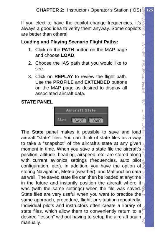
125CHAPTER 2: Instructor / Operator’s Station (IOS)
If you elect to have the copilot change frequencies, it’s always a good idea to verify them anyway. Some co pi lots are bet ter than others!Loading and Playing Scenario Flight Paths:
Click on the 1. PATH button on the MAP page and choose LOAD.Choose the IAS path that you would like to 2. see.Click on 3. REPLAY to review the fl ight path. Use the PROFILE and EXTENDED buttons on the MAP page as desired to display all associated air craft data.
STATE PANEL
The State panel makes it possible to save and load air craft “ state” fi les. You can think of state fi les as a way to take a “snapshot” of the aircraft’s state at any given moment in time. When you save a state fi le the aircraft’s position, altitude, heading, airspeed, etc. are stored along with current avionics settings (frequencies, auto pilot confi guration, etc.). In addition, you have the option of storing Navigation, Meteo (weather), and Malfunction data as well. The saved state fi le can then be loaded at anytime in the future and instantly position the aircraft where it was (with the same settings) when the fi le was saved. State fi les are very useful when you want to practice the same approach, procedure, fl ight, or situation repeatedly. Individual pilots and instructors often create a library of state fi les, which allow them to conveniently return to a desired “lesson” without having to setup the aircraft again manually.
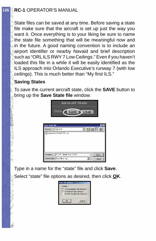
RC-1 OPERATOR’S MANUAL126
State fi les can be saved at any time. Before saving a state fi le make sure that the aircraft is set up just the way you want it. Once everything is to your liking be sure to name the state fi le something that will be meaningful now and in the future. A good naming convention is to include an airport identifi er or nearby Navaid and brief description such as “ORL ILS RWY 7 Low Ceilings.” Even if you haven’t loaded this fi le in a while it will be easily identifi ed as the ILS approach into Orlando Executive’s runway 7 (with low ceilings). This is much better than “My fi rst ILS.” Saving StatesTo save the current aircraft state, click the SAVE but ton to bring up the Save State fi le window.
Type in a name for the “state” fi le and click Save. Select “state” fi le options as desired, then click OK.
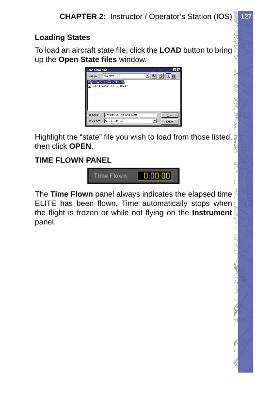
127CHAPTER 2: Instructor / Operator’s Station (IOS)
Loading StatesTo load an aircraft state fi le, click the LOAD button to bring up the Open State fi les window.
Highlight the “state” fi le you wish to load from those list ed, then click OPEN.
TIME FLOWN PANEL
The Time Flown pan el al ways in di cates the elapsed time ELITE has been fl own. Time au to mat i cal ly stops when the fl ight is fro zen or while not fl ying on the In stru ment panel.
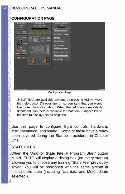
RC-1 OPERATOR’S MANUAL128
CONFIGURATION PAGE
Confi guration Page
“HELP Tips” are available anytime by pressing ALT-H. Move the help cursor (?) over any on-screen item that you would like more information about. When the help cursor reveals its document icon, help is avail able for that item. Simply click on the item to display re lat ed help tips.
Use this page to confi gure fl ight con trols, hard ware, in stru men ta tion, and sound. Some of these have already been covered during the Startup procedures in Chapter One.
STATE FILESWhen the “Ask for State File at Program Start” button is ON, ELITE will display a dialog box (on every startup) allowing you to choose any training “State File” pre vi ous ly saved. You will be positioned with the same aircraft in that spe cifi c state (in clud ing Nav data and Meteo State selected!).
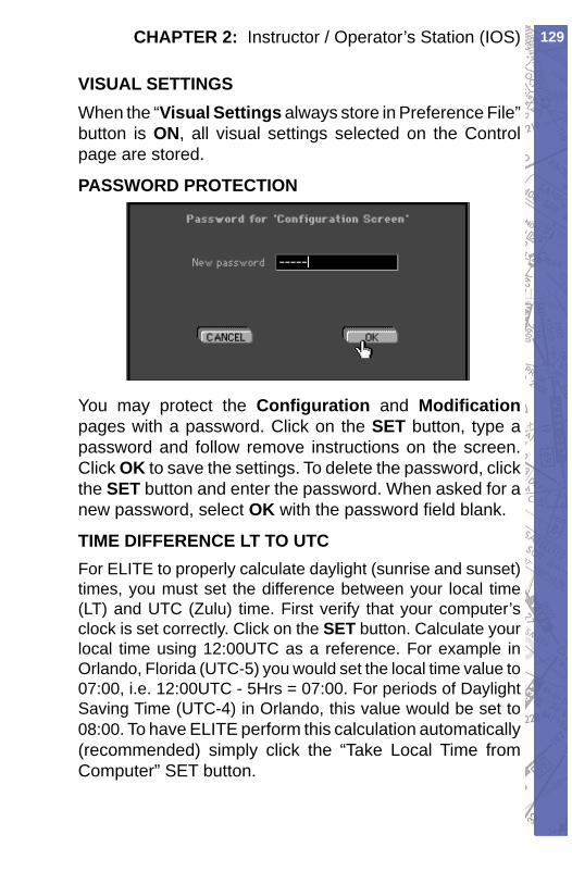
129CHAPTER 2: Instructor / Operator’s Station (IOS)
VISUAL SETTINGSWhen the “Visual Set tings always store in Pref er ence File” button is ON, all vi su al set tings se lect ed on the Con trol page are stored.
PASSWORD PROTECTION
You may protect the Confi guration and Mod i fi ca tionpages with a pass word. Click on the SET button, type a password and follow remove in struc tions on the screen. Click OK to save the settings. To delete the password, click the SET button and enter the pass word. When asked for a new password, select OK with the pass word fi eld blank.
TIME DIFFERENCE LT TO UTCFor ELITE to properly cal cu late daylight (sunrise and sun set) times, you must set the difference be tween your local time (LT) and UTC (Zulu) time. First ver i fy that your com put er’s clock is set correctly. Click on the SET button. Cal cu late your local time using 12:00UTC as a ref er ence. For example in Orlando, Flor i da (UTC-5) you would set the local time value to 07:00, i.e. 12:00UTC - 5Hrs = 07:00. For periods of Day light Saving Time (UTC-4) in Orlando, this val ue would be set to 08:00. To have ELITE perform this calculation automatically (recommended) simply click the “Take Local Time from Computer” SET button.
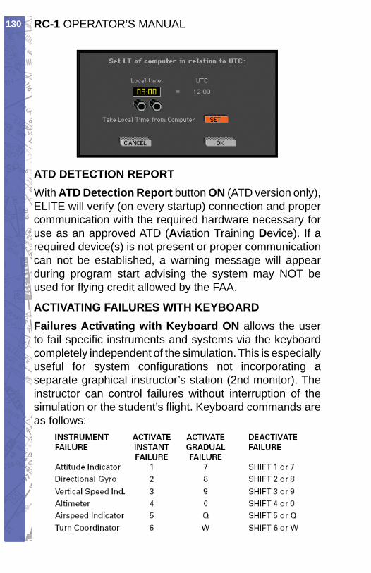
RC-1 OPERATOR’S MANUAL130
ATD DETECTION REPORTWith ATD De tec tion Report button ON (ATD version only), ELITE will verify (on every startup) con nec tion and proper com mu ni ca tion with the re quired hard ware nec es sary for use as an approved ATD (Aviation Training Device). If a re quired device(s) is not present or proper com mu ni ca tion can not be established, a warning message will appear during program start advising the system may NOT be used for fl ying credit allowed by the FAA.
ACTIVATING FAILURES WITH KEYBOARD Failures Activating with Keyboard ON allows the user to fail specifi c in stru ments and systems via the keyboard completely independent of the sim u la tion. This is especially use ful for system con fi g u ra tions not incorporating a sep a rate graphical in struc tor’s station (2nd monitor). The in struc tor can control failures with out interruption of the sim u la tion or the stu dent’s fl ight. Keyboard commands are as follows:

131CHAPTER 2: Instructor / Operator’s Station (IOS)
MEASUREMENT FOR WEIGHT & FUELYou can choose what units of mea sure ment are displayed for weight and fuel values as desired.
Weight in pounds or • kilosFuel in liters, U.S. gallons or Imperial • gallons
CHANGING HANGING COLOR OF NUMBERS
For read abil i ty, you can change the color of num bers shown on all pages (except the instrument panels.) Click on RED or YEL LOW as desired.
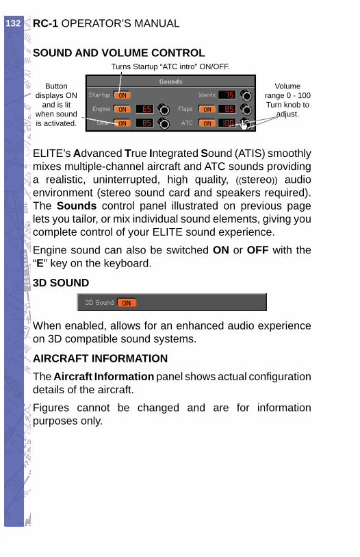
RC-1 OPERATOR’S MANUAL132
SOUND AND VOLUME CONTROL
Buttondisplays ON
and is lit when sound is activated.
Volume range 0 - 100 Turn knob to
adjust.
Turns Startup “ATC intro” ON/OFF.
a
ELITE’s Advanced True In te grat ed Sound ( ATIS) smooth ly mixes multiple-channel aircraft and ATC sounds providing a realistic, uninterrupted, high qual i ty, ((ste reo)) au dio environment (stereo sound card and speak ers re quired). The Sounds control panel il lus trat ed on previous page lets you tailor, or mix individual sound el e ments, giv ing you com plete control of your ELITE sound ex pe ri ence. Engine sound can also be switched ON or OFF with the “E” key on the keyboard.
3D SOUND
When enabled, allows for an enhanced audio ex pe ri ence on 3D compatible sound systems.
AIRCRAFT INFORMATIONThe Aircraft Information pan el shows actual con fi g u ra tion details of the air craft.Figures cannot be changed and are for information pur pos es only.
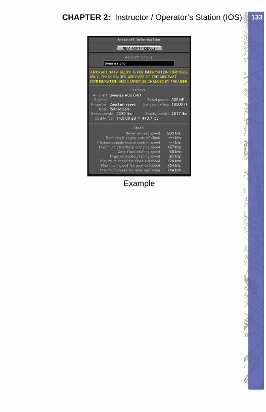
133CHAPTER 2: Instructor / Operator’s Station (IOS)
Example
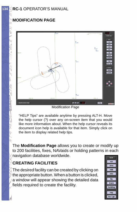
RC-1 OPERATOR’S MANUAL134
MODIFICATION PAGE
Modifi cation Page
“HELP Tips” are available anytime by pressing ALT-H. Move the help cursor (?) over any on-screen item that you would like more information about. When the help cursor reveals its document icon help is avail able for that item. Simply click on the item to display re lat ed help tips.
The Modifi cation Page allows you to cre ate or mod i fy up to 200 facilities, fi xes, NAVaids or hold ing patterns in each nav i ga tion da ta base world wide.
CRE AT ING FACILITIESThe desired facility can be created by click ing on the appropriate but ton. When a but ton is clicked, a win dow will ap pear show ing the de tailed data fi elds re quired to cre ate the facility.
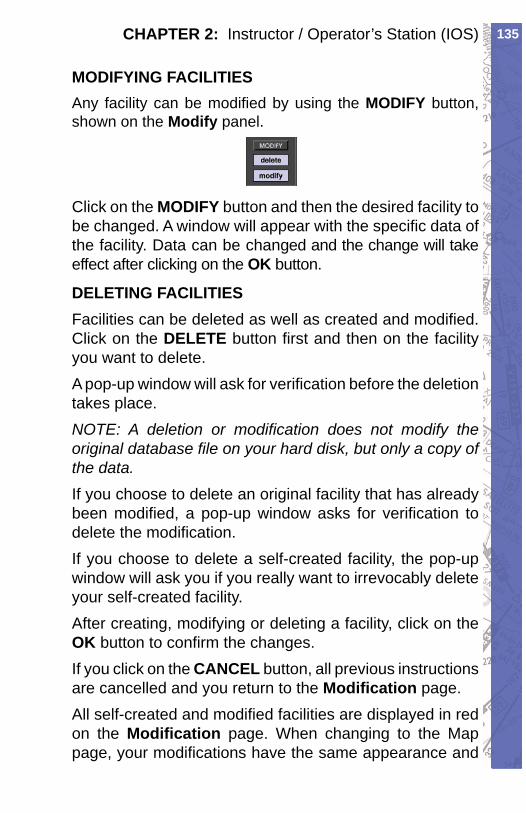
135CHAPTER 2: Instructor / Operator’s Station (IOS)
MODIFYING FACILITIESAny facility can be mod i fi ed by us ing the MOD I FY button, shown on the Mod i fy pan el.
Click on the MODIFY button and then the de sired fa cil i ty to be changed. A window will ap pear with the specifi c data of the facility. Data can be changed and the change will take effect after click ing on the OK button.
DELETING FACILITIESFacilities can be deleted as well as created and mod i fi ed. Click on the DELETE button fi rst and then on the facility you want to delete.A pop-up window will ask for ver i fi ca tion be fore the deletion takes place.NOTE: A de le tion or mod i fi ca tion does not mod i fy the original da ta base fi le on your hard disk, but only a copy of the data.If you choose to delete an original facility that has al ready been modifi ed, a pop-up window asks for ver i fi ca tion to delete the modifi cation. If you choose to delete a self-created facility, the pop-up window will ask you if you really want to ir re vo ca bly delete your self-created facility.After creating, modifying or deleting a facility, click on the OK button to con fi rm the changes.If you click on the CANCEL button, all previous in struc tions are cancelled and you return to the Mod i fi ca tion page.All self-created and modifi ed facilities are dis played in red on the Modifi cation page. When changing to the Map page, your modifi cations have the same ap pear ance and
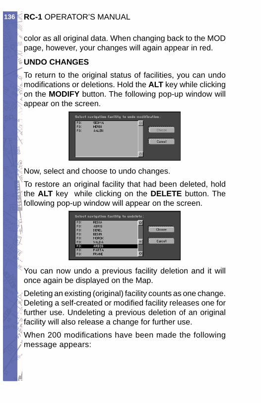
RC-1 OPERATOR’S MANUAL136
color as all orig i nal data. When changing back to the MOD page, however, your chang es will again ap pear in red.
UNDO CHANGESTo return to the original status of facilities, you can undo modifi cations or de le tions. Hold the ALT key while click ing on the MODIFY button. The following pop-up window will appear on the screen.
Now, select and choose to undo changes.To restore an original facility that had been de let ed, hold the ALT key while clicking on the DELETE but ton. The fol low ing pop-up window will appear on the screen.
You can now undo a previous facility deletion and it will once again be displayed on the Map.Deleting an existing (original) fa cil i ty counts as one change. Deleting a self-created or mod i fi ed fa cil i ty re leas es one for further use. Undeleting a previous de le tion of an original facility will also release a change for further use.When 200 modifi cations have been made the fol low ing message appears:

137CHAPTER 2: Instructor / Operator’s Station (IOS)
FACILITY INFOClick and hold the mouse on any facility to display detailed information about that facility. For run way information, click on the run way thresh old.
When facilities are in the same location or cov ered by other ones, click on the same spot once more and in for ma tion about the next facility will appear.
In the example above, several facilities nearly oc cu py the same location or are co-located. In for ma tion on these facilities is layered. Clicking the same spot re peat ed ly cycles through these layers to reveal in for ma tion about each specifi c facility.
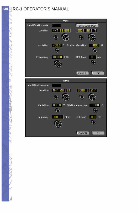
RC-1 OPERATOR’S MANUAL138
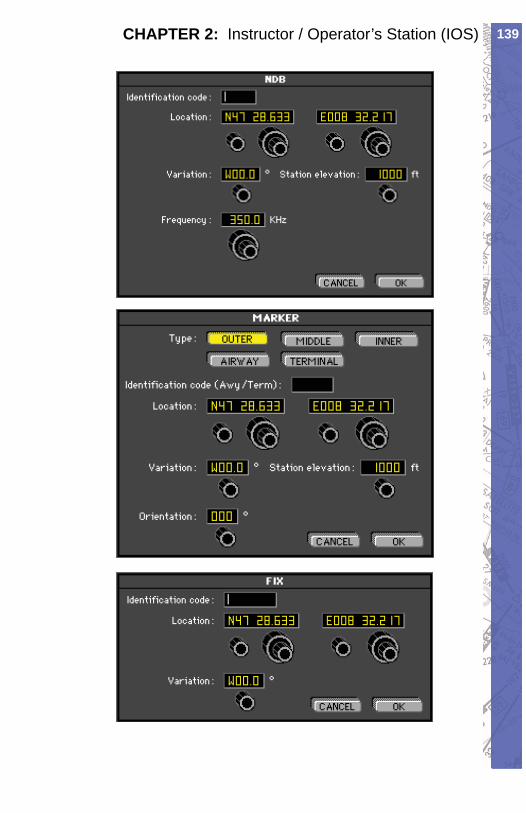
139CHAPTER 2: Instructor / Operator’s Station (IOS)
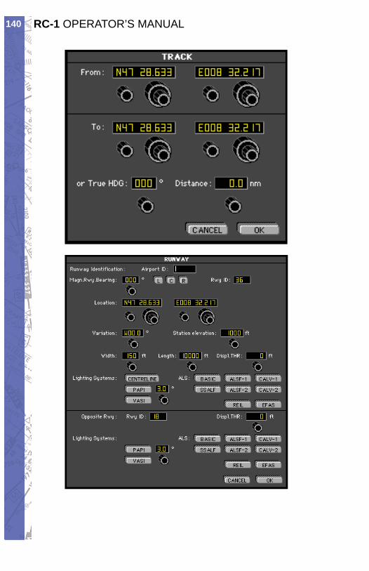
RC-1 OPERATOR’S MANUAL140
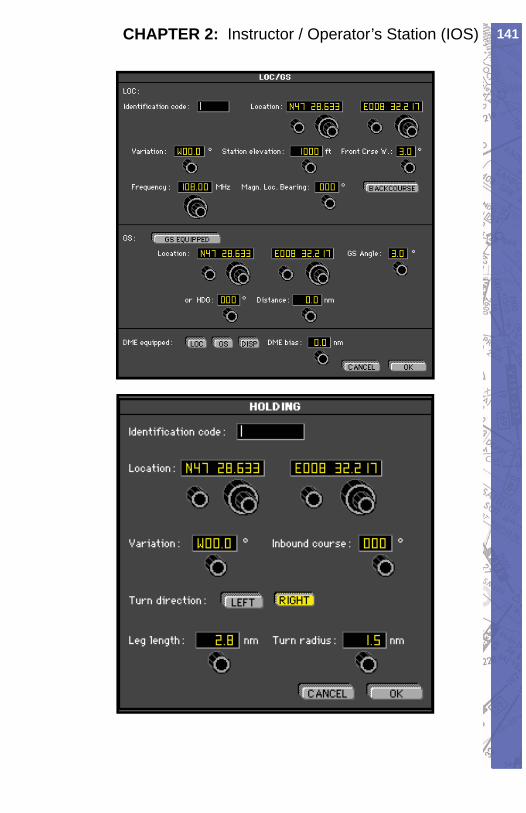
141CHAPTER 2: Instructor / Operator’s Station (IOS)

RC-1 OPERATOR’S MANUAL142
IntentionallyLeft
Blank
143CHAPTER 3: External Visual Display - GenView™
CHAPTER 3EXTERNAL VISUAL DISPLAY - GENVIEW™
GENVIEW VISUAL DISPLAYGenView™ is an add-on visual display database that will allow you to fl y in the virtual world with accurate digital elevation models (DEM) and vector data accurately depicting rivers, lakes, highways, railroads and built up areas. In addition, every airport environment is highly rendered with runway designators, appropriate runway lighting, approach light systems and properly lighted generic taxiways. Inherent to the DEM is a fully programmable dynamic weather system that further enhances the realism of fl ight by providing 3-D obstructions to visibility, cloud coverages, and several transition zones or layers for IFR, MVFR, SVFR or VFR on top. Utilizing actual downloadable METAR reports, you can create a real-time fl ight experience and save the most challenging weather scenarios for recurrent training.
GENVIEW VECTOR DATAElements in the digital elevation model depicts rivers, lakes, highways, railroads and built up areas such as cities, towns, villages, etc.
GENVIEW RUNWAY DEFINITIONSRunways will have number designators such 1. as 08 (8 for USA) or 26.Centerline lights if appropriate. Space 2. between lights is 50m.Runway edge lights if appropriate. Space 3. between lights is 50m.Approach lighting system. Distance in 4. accordance with ICAO/FAA standard.
RC-1 OPERATOR’S MANUAL144
TAXIING IN GENVIEWGeneric taxiways have been implemented in 1. GenView to allow the pilot to more closely follow the checklist sequence if used (conducting run ups, for example). Though the location of the runway and NAVaids are always accurate, the layout and orientation of taxi ways may not represent the exact layout at that airfi eld.When ELITE is fi rst loaded, the default 2. position of the aircraft is on the end of the run way. You can reposition the aircraft relative to the taxiway in three ways:
Taxi the aircraft to the position you want a. to start (least recommended, especially if you are in a hurry)Go to the b. MAP Page. Click on the aircraft symbol and hold the mouse button. Press the ALT key and drop the aircraft at the runway end and it will reposition to the taxiway parallel to the active runway.Go to the c. MAP Page. Click on the aircraft symbol and hold the mouse button. Press the SHIFT key and drop the aircraft at the runway end and it will reposition perpendicular to the active runway.
The length of the runway determines the 3. width of the taxiways (longer runways equal wider taxi ways). Wide taxiways have blue edge lights spaced at every 50m/164ft. Smaller taxiways have green centerline lights spaced at 50m/164ft. Runways with a width of 16m/52ft or less have no taxi way lights.
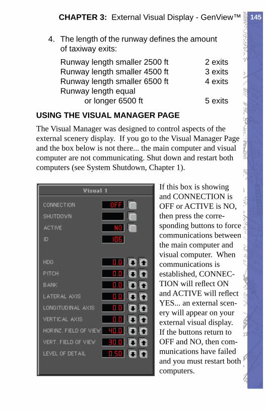
145CHAPTER 3: External Visual Display - GenView™
The length of the runway defi nes the amount 4. of taxiway exits:Runway length smaller 2500 ft 2 exitsRunway length smaller 4500 ft 3 exitsRunway length smaller 6500 ft 4 exitsRunway length equal or longer 6500 ft 5 exits
USING THE VISUAL MANAGER PAGEThe Visual Manager was designed to control aspects of the external scenery display. If you go to the Visual Manager Page and the box below is not there... the main computer and visual computer are not communicating. Shut down and restart both computers (see System Shutdown, Chapter 1).
If this box is showing and CONNECTION is OFF or ACTIVE is NO, then press the corre-sponding buttons to force communications between the main computer and visual computer. When communications is established, CONNEC-TION will refl ect ON and ACTIVE will refl ect YES... an external scen-ery will appear on your external visual display. If the buttons return to OFF and NO, then com-munications have failed and you must restart both computers.
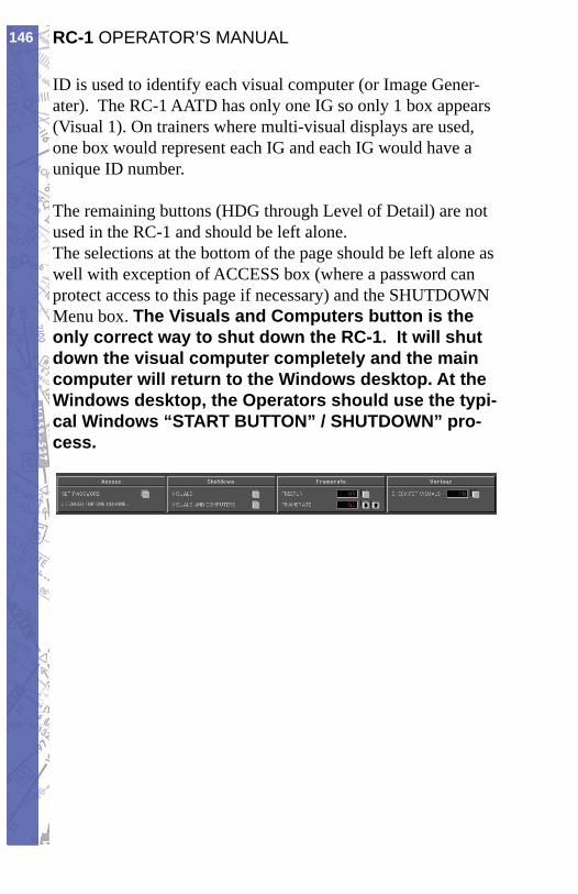
RC-1 OPERATOR’S MANUAL146
ID is used to identify each visual computer (or Image Gener-ater). The RC-1 AATD has only one IG so only 1 box appears (Visual 1). On trainers where multi-visual displays are used, one box would represent each IG and each IG would have a unique ID number.
The remaining buttons (HDG through Level of Detail) are not used in the RC-1 and should be left alone.The selections at the bottom of the page should be left alone as well with exception of ACCESS box (where a password can protect access to this page if necessary) and the SHUTDOWN Menu box. The Visuals and Computers button is the only correct way to shut down the RC-1. It will shut down the visual computer completely and the main computer will return to the Windows desktop. At the Windows desktop, the Operators should use the typi-cal Windows “START BUTTON” / SHUTDOWN” pro-cess.
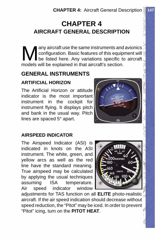
147CHAPTER 4: Aircraft General Description
CHAPTER 4AIRCRAFT GENERAL DESCRIPTION
Many aircraft use the same instruments and avionics confi guration. Basic features of this equipment will be listed here. Any variations specifi c to aircraft
models will be explained in that aircraft’s section.
GENERAL INSTRUMENTSARTIFICIAL HORIZONThe Artifi cial Horizon or attitude indicator is the most important instrument in the cockpit for instrument fl ying. It displays pitch and bank in the usual way. Pitch lines are spaced 5° apart.
AIRSPEED INDICATORThe Airspeed Indicator (ASI) is indicated in knots on the ASI instrument. The white, green, and yellow arcs as well as the red line have the standard meaning. True airspeed may be calculated by applying the usual techniques assuming ISA temperature. Air speed indicator window adjustments for TAS function on all ELITE photo-realistic aircraft. If the air speed indication should decrease without speed reduction, the “Pitot” may be iced. In order to prevent “Pitot” icing, turn on the PITOT HEAT.
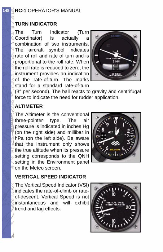
RC-1 OPERATOR’S MANUAL148
TURN INDICATORThe Turn Indicator ( Turn Coordinator) is actually a combination of two instruments. The aircraft symbol indicates rate of roll and rate of turn and is proportional to the roll rate. When the roll rate is reduced to zero, the instrument provides an indication of the rate-of-turn. The marks stand for a standard rate-of-turn (3° per second). The ball reacts to gravity and centrifugal force to indicate the need for rudder application.
ALTIMETERThe Altimeter is the conventional three-pointer type. The air pressure is indicated in inches Hg (on the right side) and millibar in hPa (on the left side). Be aware that the instrument only shows the true altitude when its pressure setting corresponds to the QNH setting in the Environment panel on the Meteo screen.
VERTICAL SPEED INDICATORThe Vertical Speed Indicator (VSI) indicates the rate-of-climb or rate-of-descent. Vertical Speed is not instantaneous and will exhibit trend and lag effects.
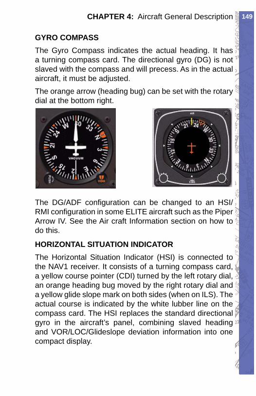
149CHAPTER 4: Aircraft General Description
GYRO COMPASSThe Gyro Compass indicates the actual heading. It has a turning compass card. The directional gyro (DG) is not slaved with the compass and will precess. As in the actual aircraft, it must be adjusted.The orange arrow (heading bug) can be set with the rotary dial at the bottom right.
The DG/ADF confi guration can be changed to an HSI/ RMI confi guration in some ELITE aircraft such as the Piper Arrow IV. See the Air craft Information section on how to do this.
HORIZONTAL SITUATION INDICATORThe Horizontal Situation Indicator (HSI) is connected to the NAV1 receiver. It consists of a turning compass card, a yellow course pointer (CDI) turned by the left rotary dial, an orange heading bug moved by the right rotary dial and a yellow glide slope mark on both sides (when on ILS). The actual course is indicated by the white lubber line on the compass card. The HSI replaces the standard directional gyro in the aircraft’s panel, combining slaved heading and VOR/LOC/Glideslope deviation information into one compact display.
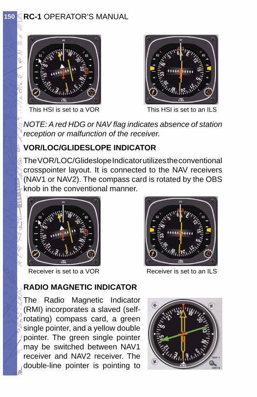
RC-1 OPERATOR’S MANUAL150
This HSI is set to a VOR This HSI is set to an ILS
NOTE: A red HDG or NAV fl ag indicates absence of station reception or malfunction of the receiver.
VOR/LOC/GLIDESLOPE INDICATORThe VOR/LOC/Glideslope Indicator utilizes the conventional crosspointer layout. It is connected to the NAV receivers (NAV1 or NAV2). The compass card is rotated by the OBS knob in the conventional manner.
Receiver is set to a VOR Receiver is set to an ILS
RADIO MAGNETIC INDICATORThe Radio Magnetic Indicator (RMI) incorporates a slaved (self-rotating) compass card, a green single pointer, and a yellow double pointer. The green single pointer may be switched between NAV1 receiver and NAV2 receiver. The double-line pointer is pointing to
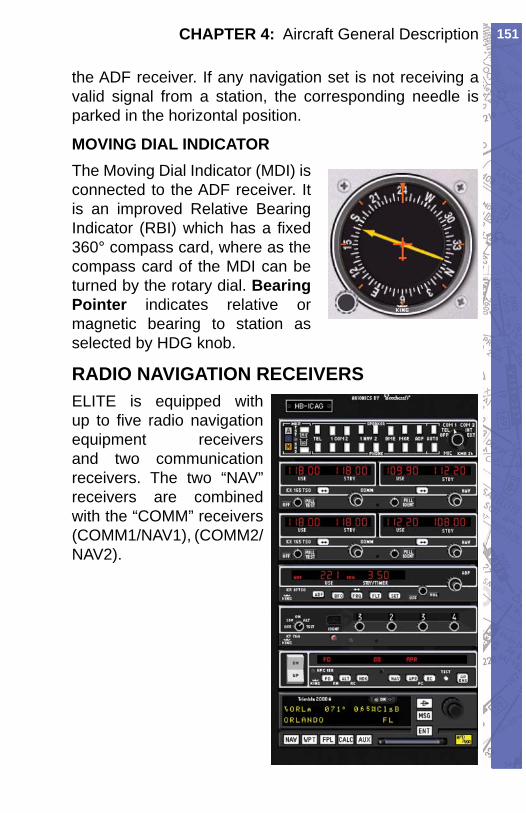
151CHAPTER 4: Aircraft General Description
the ADF receiver. If any navigation set is not receiving a valid signal from a station, the corresponding needle is parked in the horizontal position.
MOVING DIAL INDICATORThe Moving Dial Indicator (MDI) is connected to the ADF receiver. It is an improved Relative Bearing Indicator (RBI) which has a fi xed 360° compass card, where as the compass card of the MDI can be turned by the rotary dial. Bearing Pointer indicates relative or magnetic bearing to station as selected by HDG knob.
RADIO NAVIGATION RECEIVERSELITE is equipped with up to fi ve radio navigation equipment receivers and two communication receivers. The two “NAV” receivers are combined with the “COMM” receivers (COMM1/NAV1), (COMM2/NAV2).
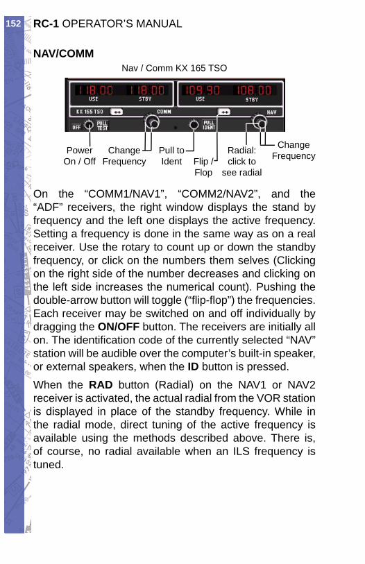
RC-1 OPERATOR’S MANUAL152
NAV/COMMNav / Comm KX 165 TSO
PowerOn / Off
ChangeFrequency
Pull toIdent Flip /
Flop
Radial:click to
see radial
ChangeFrequency
On the “COMM1/NAV1”, “COMM2/NAV2”, and the “ADF” receivers, the right window displays the stand by frequency and the left one displays the active frequency. Setting a frequency is done in the same way as on a real receiver. Use the rotary to count up or down the standby frequency, or click on the numbers them selves (Clicking on the right side of the number decreases and clicking on the left side increases the numerical count). Pushing the double-arrow button will toggle (“fl ip-fl op”) the frequencies. Each receiver may be switched on and off individually by dragging the ON/OFF button. The receivers are initially all on. The identifi cation code of the currently selected “NAV” station will be audible over the computer’s built-in speaker, or external speakers, when the ID button is pressed.When the RAD button (Radial) on the NAV1 or NAV2 receiver is activated, the actual radial from the VOR station is displayed in place of the standby frequency. While in the radial mode, direct tuning of the active frequency is available using the methods described above. There is, of course, no radial available when an ILS frequency is tuned.
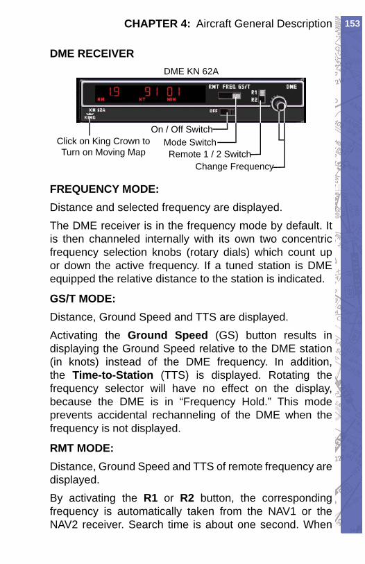
153CHAPTER 4: Aircraft General Description
DME RECEIVERDME KN 62A
Click on King Crown toTurn on Moving Map
On / Off SwitchMode SwitchRemote 1 / 2 Switch
Change Frequency
FREQUENCY MODE:Distance and selected frequency are displayed.The DME receiver is in the frequency mode by default. It is then channeled internally with its own two concentric frequency selection knobs (rotary dials) which count up or down the active frequency. If a tuned station is DME equipped the relative distance to the station is indicated.
GS/T MODE:Distance, Ground Speed and TTS are displayed.Activating the Ground Speed (GS) button results in displaying the Ground Speed relative to the DME station (in knots) instead of the DME frequency. In addition, the Time-to-Station (TTS) is displayed. Rotating the frequency selector will have no effect on the display, because the DME is in “Frequency Hold.” This mode prevents accidental rechanneling of the DME when the frequency is not displayed.
RMT MODE:Distance, Ground Speed and TTS of remote frequency are displayed.By activating the R1 or R2 button, the corresponding frequency is automatically taken from the NAV1 or the NAV2 receiver. Search time is about one second. When
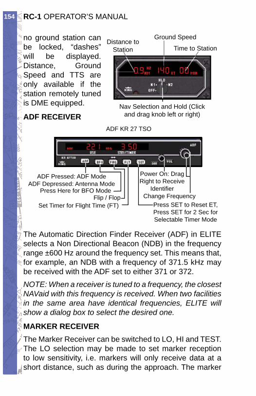
RC-1 OPERATOR’S MANUAL154
no ground station can be locked, “dashes” will be displayed. Distance, Ground Speed and TTS are only available if the station remotely tuned is DME equipped.
ADF RECEIVERADF KR 27 TSO
ADF Pressed: ADF ModeADF Depressed: Antenna Mode
Press Here for BFO ModeFlip / Flop
Power On: Drag Right to Receive
Identifi erChange Frequency
Press SET to Reset ET,Press SET for 2 Sec for Selectable Timer Mode
Set Timer for Flight Time (FT)
The Automatic Direction Finder Receiver (ADF) in ELITE selects a Non Directional Beacon (NDB) in the frequency range ±600 Hz around the frequency set. This means that, for example, an NDB with a frequency of 371.5 kHz may be received with the ADF set to either 371 or 372.NOTE: When a receiver is tuned to a frequency, the closest NAVaid with this frequency is received. When two facilities in the same area have identical frequencies, ELITE will show a dialog box to select the desired one.
MARKER RECEIVERThe Marker Receiver can be switched to LO, HI and TEST. The LO selection may be made to set marker reception to low sensitivity, i.e. markers will only receive data at a short distance, such as during the approach. The marker
Dis tance to Station
Ground Speed
Nav Selection and Hold (Click and drag knob left or right)
t Time to Station
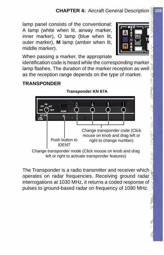
155CHAPTER 4: Aircraft General Description
lamp panel consists of the conventional: A lamp (white when lit, airway marker, inner marker), O lamp (blue when lit, outer marker), M lamp (amber when lit, middle marker).When passing a marker, the appropriate identifi cation code is heard while the corresponding marker lamp fl ashes. The duration of the marker reception as well as the reception range depends on the type of marker.
TRANSPONDERTransponder KN 67A
Change transponder code (Click mouse on knob and drag left or
right to change number)Push button to IDENT
Change transponder mode (Click mouse on knob and drag left or right to activate transponder features)
The Transponder is a radio transmitter and receiver which operates on radar frequencies. Receiving ground radar interrogations at 1030 MHz, it returns a coded response of pulses to ground-based radar on frequency of 1090 MHz.
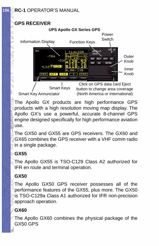
RC-1 OPERATOR’S MANUAL156
GPS RECEIVERUPS Apollo GX Series GPS
Click on GPS data card Eject button to change area coverage (North America or In ter na tion al)
Power Switch
Function Keys
Outer Knob
Inner Knob
Smart Keys
Information Dis play
Smart Key An nun ci a tor
The Apollo GX products are high performance GPS products with a high resolution moving map display. The Apollo GX’s use a powerful, accurate 8-channel GPS engine designed specifi cally for high performance aviation use.The GX50 and GX55 are GPS receivers. The GX60 and GX65 combines the GPS receiver with a VHF comm radio in a single package.
GX55The Apollo GX55 is TSO-C129 Class A2 authorized for IFR en route and terminal operation.
GX50The Apollo GX50 GPS receiver possesses all of the performance features of the GX55, plus more. The GX50 is TSO-C129a Class A1 authorized for IFR non-precision approach operation.
GX60The Apollo GX60 combines the physical package of the GX50 GPS
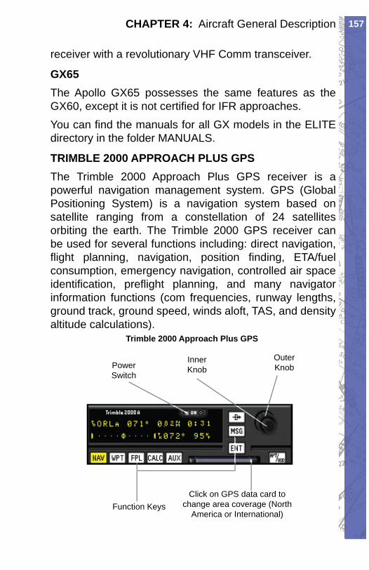
157CHAPTER 4: Aircraft General Description
receiver with a revolutionary VHF Comm transceiver.
GX65The Apollo GX65 possesses the same features as the GX60, except it is not certifi ed for IFR approaches.You can fi nd the manuals for all GX models in the ELITE directory in the folder MANUALS.
TRIMBLE 2000 APPROACH PLUS GPSThe Trimble 2000 Approach Plus GPS receiver is a powerful navigation management system. GPS (Global Positioning System) is a navigation system based on satellite ranging from a constellation of 24 satellites orbiting the earth. The Trimble 2000 GPS receiver can be used for several functions including: direct navigation, fl ight planning, navigation, position fi nding, ETA/fuel consumption, emergency navigation, controlled air space identifi cation, prefl ight planning, and many navigator information functions (com frequencies, runway lengths, ground track, ground speed, winds aloft, TAS, and density altitude calculations).
Trimble 2000 Approach Plus GPS
Click on GPS data card to change area coverage (North
America or In ter na tion al)
Power Switch
Function Keys
Outer Knob
Inner Knob
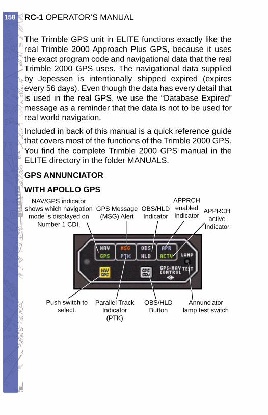
RC-1 OPERATOR’S MANUAL158
The Trimble GPS unit in ELITE functions exactly like the real Trimble 2000 Approach Plus GPS, because it uses the exact program code and navigational data that the real Trimble 2000 GPS uses. The navigational data supplied by Jepessen is intentionally shipped expired (expires every 56 days). Even though the data has every detail that is used in the real GPS, we use the “Database Expired” message as a reminder that the data is not to be used for real world navigation.Included in back of this manual is a quick reference guide that covers most of the functions of the Trimble 2000 GPS. You fi nd the complete Trimble 2000 GPS manual in the ELITE directory in the folder MANUALS.
GPS ANNUNCIATOR
WITH APOLLO GPS
Push switch to select.
GPS Message (MSG) Alert
NAV/GPS indicator shows which nav i ga tion mode is dis played on
Number 1 CDI.
Annunciator lamp test switch
Parallel Track Indicator
(PTK)
OBS/HLD Button
OBS/HLD Indicator
APPRCH enabled Indicator
APPRCH active
Indicator
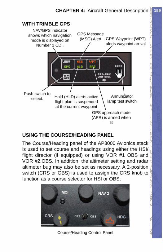
159CHAPTER 4: Aircraft General Description
WITH TRIMBLE GPS
Push switch to select.
GPS Message (MSG) Alert GPS Waypoint (WPT)
alerts waypoint arrival
GPS approach mode (APR) is armed when
lit
NAV/GPS indicator shows which nav i ga tion mode is dis played on
Number 1 CDI.
Annunciator lamp test switch
Hold (HLD) alerts active fl ight plan is sus pend ed at the current waypoint
USING THE COURSE/HEADING PANELThe Course/Heading panel of the AP3000 Avionics stack is used to set course and headings using either the HSI/fl ight director (if equipped) or using VOR #1 OBS and VOR #2.OBS. In addition, the altimeter setting and radar altimeter bug may also be set as necessary. A 2-position switch (CRS or OBS) is used to assign the CRS knob to function as a course selector for HSI or OBS.
Course/Heading Control Panel
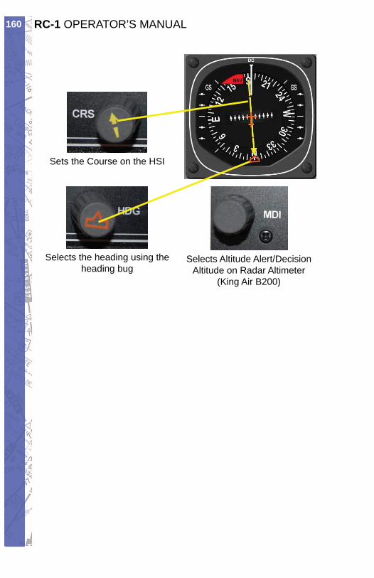
RC-1 OPERATOR’S MANUAL160
Sets the Course on the HSI
Selects the heading using theheading bug
Selects Altitude Alert/Decision Altitude on Radar Altimeter
(King Air B200)
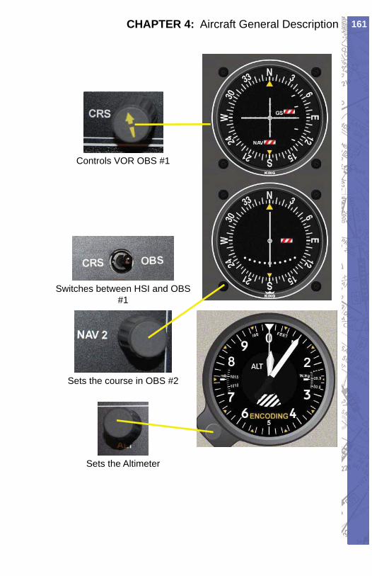
161CHAPTER 4: Aircraft General Description
Controls VOR OBS #1
Switches between HSI and OBS #1
Sets the course in OBS #2
Sets the Altimeter

RC-1 OPERATOR’S MANUAL162
IntentionallyLeft
Blank
163INDEX
Symbols3D Sound 132
AACC. See Area Control CenterACFT Information 63ACP. See Airlift Command PostActive Metar 97ADF receiver 151Advanced True Integrated
Sound 132ATIS 132
Aerodrome Actual Weather METAR And SPECI Decode 106
Aerodrome Flight Information Service 77
A/FD. See airport/facility directory
AFIS. See Aerodrome Flight Information Service
Aircraft Identifi cation 122Aircraft Information 132Aircraft Module 14Aircraft Panel 121Aircraft Position 37Aircraft Snapping 45
Centering 46Map Scrolling 45
Aircraft State. See State PanelAir / Ground 77Airlift Command Post 75Airport Advisory Service 77airport/facility directory 75Airport Frequency Information
75Communication box 75
Frequency Column 75Airport Radar Service Area 76
Airspeed Panel 59Air Traffi c Control Tower 76Altimeter 90Altitude Grid 60Altitude Panel 58AP3000 4, 11, 159
Course/Heading Panel 159Apollo GX 156Apollo Series GPS 2APP. See Approach ControlApproach Control 75Area Control Center 75ARR. See Arrival ControlArrival Control 76Arrival Service 77ARSA. See Airport Radar
Service AreaAssembly 1ATD 8ATD Detection Report 130ATI. See Automatic Terminal
Information ServicesATIS. See Automatic Terminal
Information ServicesAutomatic Terminal Information
Service 76Automatic Weather Observing
Station 76Autopilot 2Avionics xAWO. See Automatic Weather
Observing StationAWOS. See Automatic Weather
Observing Station
BBearing Pointer 151BEARING TO 64Beech
Baron 58 xi, xii
INDEX
RC-1 OPERATOR’S MANUAL164
Bonanza 836 xiiBonanza A-36 xiSeneca III xii
Bendix King Silver Crown Avionics 2
BKN 89
CCalibration screen 15CARS. See Community
Aerodrome Radio StationCAVOK. See Ceiling/Visibility OKCeiling/Visibility OK 89Cessna
172R xi172 RG xiC172 R xiC172 RG xiC182 xi
Chronometer 4CLD. See Clearance DeliveryClearance Delivery 76Clearance Pre-Taxi 76Cockpit 4Community Aerodrome Radio
Station 77Confi guration 10Confi guration Page 16, 17, 31,
128Aircraft Information 12Color for Digits 12Controls 12General Settings 12, 13, 128Handling 12Hardware Confi guration 12Instrument 12Sounds 12State Files 128Units 12
CONFIGURATION page 10Control 76Control Page 33, 118
Preset Level of Detail
(GenView) 119Scenery/Runway Lighting 120Visual Panel 118
Set Date and Time 119Controls Calibraton 10Control Screen
State Files 125control sensitivity, adjusting 22Copyright xiiiCPT. See Clearance Pre-TaxiCTL. See Control
DDEP. See Departure ControlDeparture Control 76Departure Service 77DIR. See Director (Approach
Control/Radar)Director (Approach Control/
Radar) 76
EElectric pitch trim 2Emergency 76EMR. See EmergencyEngine Startup 121Extend Button 63External Display System 5
FFailures Activating with
Keyboard ON 130FEW 89FIR. See Flight Information
RegionFIS. See Flight Information
ServiceFlight Controls 4
Calibration 15Flight Data Recorder 3Flight Information Region 39Flight Information Service 77
165INDEX
Flight Service Station 76Freeze 34FREEZE button 11FSS. See Flight Service StationFuel Imbalance 121Fuel / Load Panel 121
GGate Control 76GenView 2, 143
Runway Defi nitions 143Taxiing 144Vector Data 143
Glideslope Limits 60GND. See Ground ControlGPS Annunciator 158
Apollo GPS 158Trimble GPS 159
Ground Control 76GTE. See Gate Control
HHeading Panel 58HEL. See Helicopter FrequencyHelicopter Frequency 76HotPlates 78
IIAS 59. See also Instrument
Approach ScenariosIC. See Initial ContactIDENT button 49ILS 42Image Generator 8INF. See InformationInformation 76Initial Contact 77Instructor / Operator Station 5,
25Instrument 34Instrument Approach Scenarios
54, 123
Instrument Confi guration 23Instruments 147
Airspeed Indicator 147Altimeter 148Artifi cial Horizon 147ASI. See Airspeed IndicatorGyro Compass 149Horizontal Situation Indicator
149HSI. See Horizontal Situation
IndicatorMDI. See Moving Dial IndicatorMoving Dial Indicator 151Radio Magnetic Indicator 150RMI. See Radio Magnetic
IndicatorTurn Coordinator 148Turn Indicator 148Vertical Speed Indicator 148VOR/LOC/Glideslope Indicator
150VSI. See Vertical Speed
IndicatorIOS. See Instructor / Operator
Station
J
KKing Silver Crown x
LLanguage other than English
78Level of Detail 119License Agreement xiiiLimits 15local time (LT) 129LOD. See Level of Detail
MMAG HDG. See Heading Panel
RC-1 OPERATOR’S MANUAL166
Route Button 70Route Planner 72
Add Point 72Move Point 73Remove Point 72Route Info 73
Shortcuts 73GenView Specifi c Shortcuts
74Mapping 3MAP profi le view 59Map Scale 37Map Zoom Levels 46
Custom 46Storing 46
Master Panel Power 21Metar Files
Downloading METAR FilesAdvanced Method 101
Metar Page 29, 97Downloading METAR Files
100Basic Method 100
METAR Data 98Wind and Gusts 98
Meteo Files 94Load 94Save 94
Meteo Page 28, 81Actual Weather Column 83Ceiling (Standard View) 87Clouds Page 81, 82Dynamic WX 83Layout (GenView) 82Static Weather 84Transition Zones 85
GenView 85Standard View 86
Turbulence 86Visibility (GenView) 87Wind 85Wind Direction 86Wind Page 81, 82
Malfunctions 2Malfunctions Page 27, 108
ARM button 109, 110Clear all failures 116Engine Failures 112FAIL 109Failure States 116Failure Time Window 110Flaps 112Gear 112Immediate Failure 111Instrument INOPs 114Instruments and Systems
Failures 109Malfunction fi les
Open 116Save 116
Random Failures 114Receivers 112Ref. Failure Time 117Reset to ARM 116Specifi c Time Failure 111
Manual Reposition 41Map Borders 39Map Cursors 38
Active Runway 38Add point 38Change/Move Point 38Heading/Distance 38Normal cursor 38Remove point 38Zoom in cursor 38Zoom limit 38Zoom out cursor 38
Map Information 39Map page 10, 32, 35, 66, 144
Path Button 68Clear 69Load 69Save 69
Print Button 70Print 70Save 70
167INDEX
Wind Speed 86METEO Page 91, 109Meteorological page. See Meteo
PageMilitary Frequency 78Modifi cation Page 30, 134
Facilities 134, 135Facility Info 137MODIFY button 136Undo Changes 136
MonitorSecond 22
MUL. See MulticomMulticom 76Multiple ILS/Deselection 42
NNAV Data
Changing 52Loading 52
NAV database 41Nav Data Symbols 37
Airport Symbol 38Communication frequencies
38DME 37FIX 37Glide Path Track 37Glideslope transmitter 38Holding 37Localizer transmitter 38Marker 37NDB 37Runway with displaced
threshold 38VOR 37VOR DME 37
Navigation Data 2Navigation Databases 14, 50NAVset. See NAV database
Creating 53Null Zone 16
OODP. See Parametres (French
Radio)Operations 76OPS. See OperationsOVC 89. See also OVERCASTOVERCAST 87, 88, 89
PParametres (French Radio) 76Password Protection 129Pilot Controlled Lighting (Air /
Ground) 78Piper
Archer III xiArrow xiArrow IV xiiSeneca III xi
PITOT HEAT 147POWER light 21Power Quadrant 16Profi le Button 59Profi le Scroll 60Program Menu 25Pro Panel II 8
QQuit 34
RRAC. See Ready to Assemble
CockpitRadar altimeter 2Radar Only Frequency 76Radial Button 64Radio 76Radio Navigation Receiver 151
ADF Receiver 154Apollo GX
GX50 156GX55 156
RC-1 OPERATOR’S MANUAL168
GX60 156GX65 157
DME Receiver 153Frequency Mode 153Ground Speed (GS) button
153RMT Mode 153Time-to-Station (TTS) 153
GPS Receiver 156Marker Receiver 154NAV/COMM 152RAD button 152Transponder 155Trimble 2000 Approach Plus
GPS 157Ramp / Taxi Control 76RBI. See Relative Bearing
IndicatorRCAG. See Remote
Communications Air to Ground
RCO. See Remote Communications Outlet
RDO. See RadioRDR. See Radar Only FrequencyReady to Assemble Cockpit 4Reference Meteo Time 95
RESET 96Relative Bearing Indicator 151Remote Communications Air to
Ground 78Remote Communications Outlet
78Remote Flight Service Station
76Reposition 39RFS. See Remote Flight Service
StationRFSS. See Remote Flight
Service StationRMP. See Ramp / Taxi ControlRSA. See Airport Radar Service
Area
Rudder trim 2
SSCT 89SEL. See Single Engine LandShow Facilities 47, 49SHUTDOWN BOX 11Single Engine Land 4SKC. See Sky ClearSky Clear 89Sound and Volume Control 132Spot Weather 49Spot WX 3Startup 1State Panel 57, 125Station Plot 104Structural Icing 91Sunrise 119Sunset 119System Features 1System Settings
Changing 14
TTCA. See Terminal Control AreaTemperature 91Terminal Control Area 76, 77Terminal Radar Service Area 76Throttle Quadrants
Changing 17Time Flown Panel 127TIME/SPEED/DISTANCE 71Transcribed Weather Broadcast
76TRANSMIT light 21Transponder Tag 48Trimble 2000 Approach Plus™
GPS 2TRS. See Terminal Radar
Service AreaTRSA. See Terminal Radar
Service AreaTWE. See Transcribed Weather
169INDEX
BroadcastTWEB. See Transcribed Weather
BroadcastTWR. See Air Traffi c Control
Tower
UUAC. See Upper Area Control
CenterUNI. See UnicomUnicom 77Upper Area Control Center 77USB Button 22UTC (Zulu) 129
VVirtual Flight Data Recorder 65
Fast-Forward Button 66Play/Pause Button 66Replay 65REPLAY options button 67Rewind Button 66Slow Button 66Stop Button 66
Visual Manager Page 145VISUAL MANAGER Page 11VISUALS AND COMPUTERS
button 11Visual Settings 129VOL. See VOLMETVOLMET 77
WWeather 3Weight & Fuel 131WIBU key 5Wind Barb Description 105
X
Y
Yaw Control 122
Z

RC-1 OPERATOR’S MANUAL170
IntentionallyLeft
Blank

171SUPPLEMENTS
SUPPLEMENTS
This section will include supplemental instructions for standard equipment for the RC-1 and also be used for the insertion of optional products or future product additions or releases.

RC-1 OPERATOR’S MANUAL172
IntentionallyLeft
Blank

1IPM
ELITE IPM(Interconnectivity Protocol Module)
INSTALLATION GUIDE
IPM is an add-on product to ELITE that outputs fl ight data in formats (or protocols) common to most handheld GPS or Electronic Flight Bag (EFB) devices used for actual aircraft navigation. Connecting you devices to ELITE offers a new dimension in training and fl ight simulation.
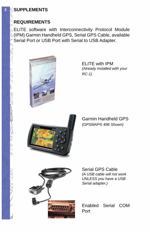
SUPPLEMENTS2
ELITE with IPM(Already installed with your RC-1)
Garmin Handheld GPS(GPSMAP® 496 Shown)
Serial GPS Cable(A USB cable will not work UNLESS you have a USB Serial adapter.)
Enabled Serial COM Port
REQUIREMENTSELITE software with Interconnectivity Protocol Module (IPM) Garmin Handheld GPS, Serial GPS Cable, available Serial Port or USB Port with Serial to USB Adapter.
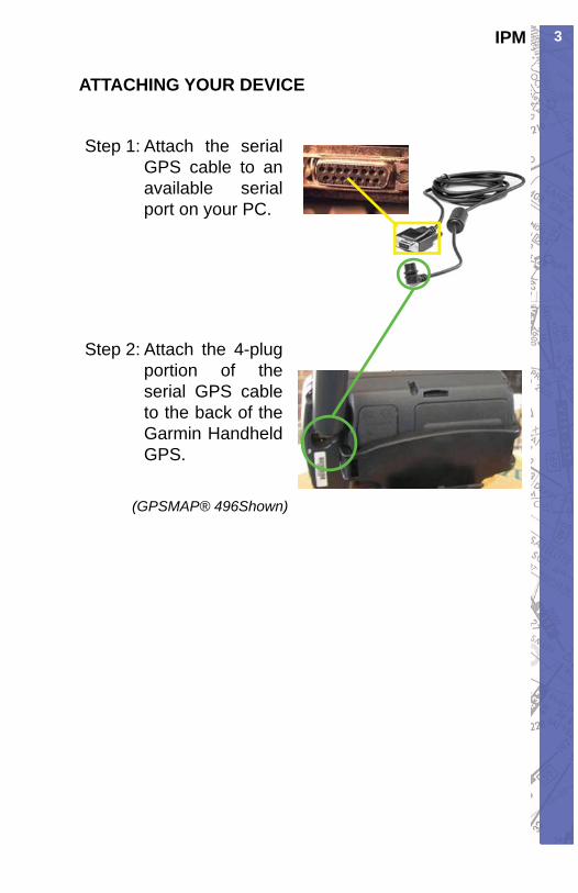
3IPM
ATTACHING YOUR DEVICE
Attach the serial Step 1: GPS cable to an available serial port on your PC.
Attach the 4-plug Step 2: portion of the serial GPS cable to the back of the Garmin Handheld GPS.
(GPSMAP® 496Shown)
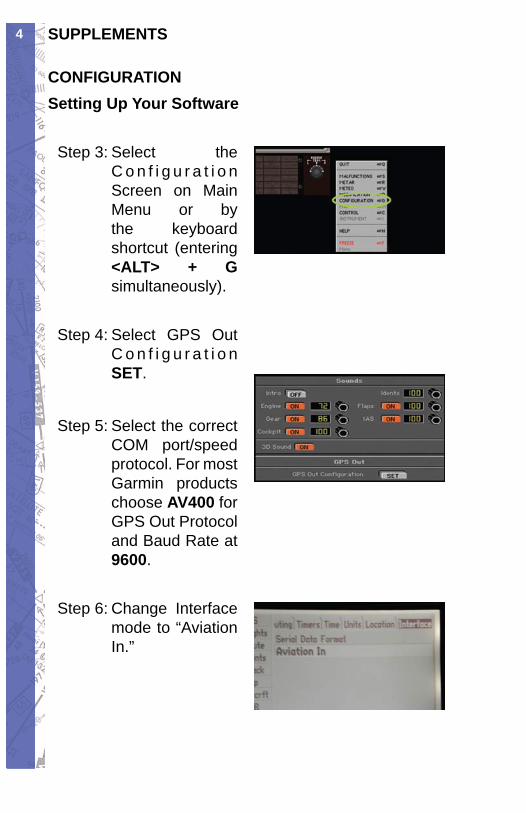
SUPPLEMENTS4
CONFIGURATIONSetting Up Your Software
Select the Step 3: C o n f i g u r a t i o n Screen on Main Menu or by the keyboard shortcut (entering <ALT> + G simultaneously).
Select GPS Out Step 4: C o n f i g u r a t i o n SET.
Select the correct Step 5: COM port/speed protocol. For most Garmin products choose AV400 for GPS Out Protocol and Baud Rate at 9600.
Change Interface Step 6: mode to “Aviation In.”
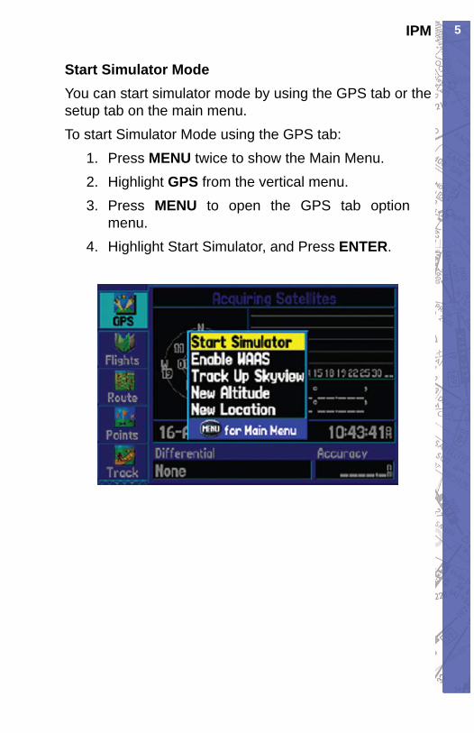
5IPM
Start Simulator ModeYou can start simulator mode by using the GPS tab or the setup tab on the main menu.To start Simulator Mode using the GPS tab:
Press 1. MENU twice to show the Main Menu.Highlight 2. GPS from the vertical menu.Press 3. MENU to open the GPS tab option menu.Highlight Start Simulator, and Press 4. ENTER.
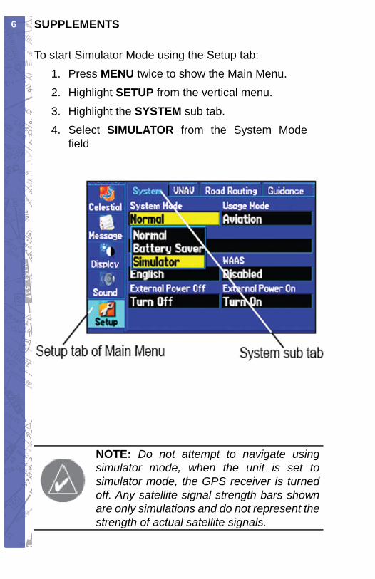
SUPPLEMENTS6
To start Simulator Mode using the Setup tab:Press 1. MENU twice to show the Main Menu.Highlight 2. SETUP from the vertical menu.Highlight the 3. SYSTEM sub tab.Select 4. SIMULATOR from the System Mode fi eld
NOTE: Do not attempt to navigate using simulator mode, when the unit is set to simulator mode, the GPS receiver is turned off. Any satellite signal strength bars shown are only simulations and do not represent the strength of actual satellite signals.
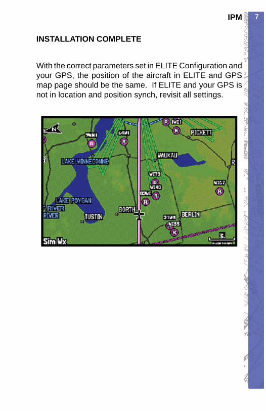
7IPM
INSTALLATION COMPLETE
With the correct parameters set in ELITE Confi guration and your GPS, the position of the aircraft in ELITE and GPS map page should be the same. If ELITE and your GPS is not in location and position synch, revisit all settings.

SUPPLEMENTS8
IntentionallyLeft
Blank