Embed Size (px)
Citation preview

Diamond Tread 4%/6% Black
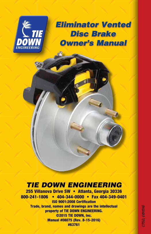
Eliminator VentedDisc Brake
Owner’s Manual
Eliminator VentedDisc Brake
Owner’s Manual

Diamond Tread 4%/6% Black
Bi-metal PistonBi-metal piston combines a stainless steel outer jacket with an anodized aluminum inner sleeve to shed braking heat 5X faster than one piece stainless pistons. The stainless steel outer jacket is specifically designed for road salt and saltwaterconditions. U.S. Patent #7,028,813
Oversized Rubber BootRubber boot is 50% thicker by design and provides for positive piston withdrawal.
Stainless Steel Bleeder ValvesType 304 stainless steel with teflon coating for easy bleeding.
Stainless Steel Slider PinsStainless steel provides corrosion resistance for smoother brake operation. The hex head design allows fast removal for easy servicing.
Vented RotorEliminator rotors are vented to provide faster cooling and are available in E-coat, GalvX coatings and Stainless Steel.
Aluminum CaliperAluminum sheds heat 5X faster than traditional cast iron, resulting in cooler braking even in the worst conditions. E-coat finish protects the caliper from salt buildup in harsh environments.
Lifetime Ceramic/Stainless Steel Brake PadsNo Dust, No Rust. Lifetime Warranty. Automotive quality ceramic brake pads with stainless steel backing plates.
Slim DesignSlim caliper design allows for short axle overhangs and aids in faster cooling.
Bronze BushingOil impregnated bronze bushings last longer, slide smoother and will NOT corrode.
Eliminator Vented Disc Brakes Exclusive Features
“Whenever possible, the tendency is to use an aluminum alloy in order to reduce weight. These alloys are much lighter and are also much better heat conductors: 220W/m.˚K for aluminum compared to 44 W/m.˚K for cast iron”. That’s 5X faster!
*Haynes Automotive Disc Brake Manual

Diamond Tread 4%/6% BlackDiamond Tread 4%/6% Black
2
Read your trailer manufacturer’s operating manual and follow the towing vehicle’s guidelines for towing capability, hitch requirements and other towing information.
Congratulations on your decision to have Tie Down Engineering vented rotor disc brakes with aluminum calipers installed on your trailer. Disc brakes have many advantages over drum brakes. These include: • Greater fade resistance • Self cleaning • Self adjusting • Less maintenance • Greater stopping power • Easy visual inspection without removing any parts
Tie Down Engineering vented rotor disc brakes with aluminum calipers have many exclusive features not found on automotive type brakes modified for trailer use. Please see our web site at tiedown.com for further information on features and benefits.
Vented rotor disc brakes are designed to activate when the vehicle’s brakes are applied. As the vehicle stops or slows, the momentum of the trailer pushes forward, developing pressure in the actuator (master cylinder), which is used to apply pressure to the brakes.
Operating Information Read and understand the towing information for your trailer and actuator. Check your trailer frequently for any leaks in the hydraulic system, which includes the actuator, brake lines and brakes. The brake rotors are made of steel and will show surface rust on the braking surface when not used for a week or more. Normal use will wipe the rust off of the rotorsurface. If the trailer is used in salt water, it is recommended that you rinse off the brakes with fresh water after each use to reduce the effects of saltwater corrosion. Your trailer should tow easily. Disc brakes operate at a higher temperature than drum brakes. This is normal and is very similar to the way disc brakes operate on yourvehicle. If for any reason your trailer does not tow easily or wants to veer to one side, stop and investigate immediately and solve the problem. Towing a trailer (even a trailer with brakes) puts an added load on the tow vehicle’s handling and braking capabilities. Do not follow too closely; you will need extra distance to maneuver and to stop. Towing downhill puts added stress on both the tow vehicle and the trailer. Slow down before you start on an incline and maintain a controlled downhill speed with repeated application of brakes followed by a cooling period when brakes are not applied. It is very important to start off with a slow speed and maintain it rather than trying to slow down from a higher speed. Should you feel the brakes on the trailer or tow vehicle are running hot or showing signs of fade, stop immediately on the side of the road and allow the brakes to cool before resuming your trip.
Vented Rotor Disc Brakes, w/Aluminum Caliper

Diamond Tread 4%/6% BlackDiamond Tread 4%/6% Black
3
Vented Rotor Disc Brakes, w/Aluminum Caliper
Should you feel the tow vehicle and trailer brakes are not working as they should, have the tow vehicle and trailer inspected. Make sure your trailer’s Gross Vehicle Weight (GVW) is within the tow vehicles capacity. If your trailer has multiple axles, verify that the GVW of the trailer does not exceed the capacity of the brakes, which is 3750 lbs on 10-inch (5 lug) brakes and 6000 lbs on 12-inch (6 lug) brakes, per axle. Some states require brakes on all axles. Check with your state laws and the state laws of where you will be using your trailer. After long trips or downhill towing, your brakes could be very hot and it is a good idea to let them cool down before submerging in cold water. The change in temperature of very hot brakes submerged in water creates additional stress on the parts and could cause damage to your brakes. Pads must be replaced when the friction material is 3/32” or less. Original Tie Down Engineering brake pads have a GalvX coated backing plate that aids in corrosion resistance. Use DOT 3 brake fluid only. DO NOT USE SILICONE BASED BRAKE FLUID. When backing a trailer with disc brakes, you must have a lockout lever or preferably an electrically operated solenoid to stop brake pressure to the disc brakes. The solenoid is mounted at the rear of the actuator, between the master cylinder and brake line. It has a wire connected to your back up lights to stop or redirect the fluid to keep the brakesfrom operating.Replace Brake Pads 1. Elevate the trailer using the manufacturers instructions. Always use jack stands for support. Do not depend on a jack to support the trailer. Block wheels to keep trailer from rolling. 2. Remove the tire/wheel assembly. Inspect the rotor surface. Check for excessive wear or grooves that may affect braking. Original “Cap Style” rotor thickness is .939” with a minimum thickness of .85” or 21.6 mm. Original “Integral” rotor thickness is .75” with a minimum thickness of .67” or 17 mm. 3. Inspect brake pads. Minimum thickness is 3/32”. Pads should be replaced if below this width. 4. Remove the caliper by unscrewing the slider pins from the mounting bracket. Be careful to hold the caliper in place so that it does not fall and pull on the brake hose. The inside pad is spring loaded in the caliper piston. Pry this pad out gently with a flat blade screwdriver. The outside pad is held in place with two metal tabs. Use a large pair of pliers to straighten the tabs to remove the outside pad. 5. Clean the rotor with a brake cleaning spray. Replace brake pads in reverse order. The tabs should only be bent enough to hold the pad in place. Do not bend tab too far or the pad will not seat correctly. Outside pad should be able to “wiggle” after tab is bent. 6. Clean threads on slider bolts and mounting plate. Apply a coating of LIQUID LOCTITE® 263 or equivalent to the internal threads of the mounting bracket only. Insert slider pins through backside of caliper into mounting bracket. Use a 7/16” hex socket and tighten both pins to 40 ft. lbs.DO NOT REASSEMBLE WITHOUT APPLYING LIQUID LOCTITE® TO THE BACKING PLATE. SLIDER PINS COULD BACK OUT AND CAUSE PERMANENT DAMAGE TO YOUR BRAKES AND TRAILER.

Diamond Tread 4%/6% BlackDiamond Tread 4%/6% BlackDiamond Tread 4%/6% Black
4
Removing Hub/Rotor 1. If your axle has an integral style rotor, then the hub and rotor are one piece, and will come off as one. 2. If you have a cap style rotor, the rotor will be removed after the wheel and caliper are removed. The hub will come off separate. 3. Elevate the trailer using the manufacturers instructions. Always use jack stands for support. Do not depend on a jack to support the trailer.Block wheels to keep trailer from rolling. 4. Remove the tire/wheel assembly. 5. Remove the caliper by unscrewing the slider pins from the mounting bracket. Be careful to hold the caliper in place so that it does not fall and pull on the brake hose. Support the caliper so that it does not “hang” from the brake line. 6. Remove the grease cap from the hub by prying around the edge of the cap. 7. Bend the locking tang washer to the “free” position. If spindle is equipped with a cotter key, straighten cotter key to remove. 8. Remove the spindle nut in a counter clockwise direction and remove the spindle washer. 9. Remove the hub from the spindle. Be careful not to allow bearings to fall out of the hub. 10. Clean bearing and cup surfaces, repack with lithium marine grade grease. 11. Place hub on spindle in reverse order as listed above. Rotate the hub while tightening the spindle nut to approximately 50 ft. lbs. This translates into full hand pressure with a 12” long set of pliers or 12” long wrench. 12. Loosen the spindle nut to remove the torque, do not rotate hub. 13. Finger tighten the spindle nut until snug, backing out only to line up the locking tang washer. 14. Bend the locking tang tab in place, Replace rotor. 15. Clean threads on slider bolts and mounting plate. Apply a coating of LIQUID LOCTITE® 263 or equivalent to the internal threads of the mounting bracket only. Tighten bolts to 40 ft. lbs. DO NOT REASSEMBLE WITHOUT APPLYING LIQUID LOCTITE® TO THE BACKING PLATE. SLIDER PINS COULD BACK OUT AND CAUSE PERMANENT DAMAGE TO YOUR BRAKES AND TRAILER. 16. Replace cap. Install tire/wheel assembly and tighten wheel nuts to trailer manufacturer specifications. Test wheel for excessive tightness or excessive play. Readjust if necessary. 17. Road test vehicle in a safe place before traveling on main roads in traffic.
VentedCaliper Slider
Pin
Bleeder Valve
Brake LineOut
Spindle/Axle
Nut/Bolt
BrakeFlange
MountingPlate
Integral StyleRotor

Diamond Tread 4%/6% BlackDiamond Tread 4%/6% Black
5
1. On a bare axle attach mounting plate to the brake flanges on the axle. Preferred position is at “12:00” high or to the back side. Exact positioning will be determined by the brake flange. Use 7/16” x 1-1/4” zinc hex bolts, lock nuts/washers and torque to 40 lbs. Note: brake mounting plates can have 2 or 4 holes for attaching to the axle.
2. If installation is on a completed trailer, remove tire/wheel. This would be a good time to repack wheel bearings and inspect the bearings and seals if it has not been done recently.
3. Install hub (use existing instruction on installing hubs).
4. Place cap style rotor over hub. Make sure the hub face is clean with a smooth surface or:
4a. If installing an integral or “one piece hub rotor”, install rear bearing and seal. Grease bearings, then install front bearings.
Step 1 Step 3
Step 4
Cap Style Rotor Integral Rotor
Step 4a
Installation/Replacement Instructions forVented Disc Brakes

Diamond Tread 4%/6% BlackDiamond Tread 4%/6% BlackDiamond Tread 4%/6% Black
6
Step 5
Step 6
5. Place caliper over rotor and mounting plate. A bleeder valve must be in the up position (see above). Check both calipers for this position. Some calipers have two valves others have only one. 6. Apply a coating of LIQUID LOCTITE® 263 or equivalent to threads on the mounting plate. Insert slider pins through backside of caliper into mounting plate. Use a 7/16” hex socket and tighten both pins to 40 ft. lbs. Check for binding, make sure rotor spins freely.
NOTE: If the pins are removed after step 6, the pins/mounting bracket threads must be cleaned. Apply LOCTITE® 263 to the internal threads of the mounting bracket only. Be careful not to get LOCTITE® on slider pins or bushings.
7. Connect brakes lines and bleed brakes before using.
IMPORTANT:When bleeding calipers, always use the top most bleeder valve to allow air to escape from the caliper piston.
Always bleed through the upper most bleeder valve.

Diamond Tread 4%/6% BlackDiamond Tread 4%/6% Black
7
# Eliminator Rotors Part #1 8.0” Vented Integral Rotor - E-coat 46902P2 9.6” Vented Integral Rotor - E-coat 46845P2 9.6” Vented Integral Rotor - GalvXL 46845X2 9.6” Vented Integral Rotor (2150#) - E-coat 46845HEC2 9.6” Vented Integral Rotor (2150#) - GalvXL 46845HX3 9.6” Vented Turbo Lube/Vortex Integral Rotor - E-coat 46845TLP3 9.6” Vented Turbo Lube/Vortex Integral Rotor - GalvXL 46845TLX4 10” Vented Cap Rotor - E-coat 46246P4 10” Vented Cap Rotor - GalvXL 46246X4 10” Vented Cap Rotor - Stainless Steel 468855 12” Vented Integral Rotor - E-coat 46895P5 12” Vented Integral Rotor - GalvXL 46895X6 12” Vented Cap Rotor - E-coat 46247P6 12” Vented Cap Rotor - GalvXL 46247X6 12” Vented Cap Rotor - Stainless Steel 468877 12” Vented Integral Turbo Lube/Vortex Rotor - E-coat 46895TLP7 12” Vented Integral Turbo Lube/Vortex Rotor - GalvXL 46895TLX8 13” Vented Cap Rotor - E-coat 46890P8 13” Vented Cap Rotor - GalvXL 46890X8 13” Vented Cap Rotor - Stainless Steel 468899 13” Vented Integral Rotor - E-coat 46898EC9 13” Vented Integral Rotor - GalvXL 46898X
# Brake Part Descriptions Part #1 Caliper Assembly (8” rotor) 46901A2 Caliper Assembly (9.6”, 10” & 12” rotors) 46304S3 Caliper Assembly - Stainless Steel (9.6”, 10” & 12” rotors) 46804A4 Caliper Assembly (13” cap rotor) 46802A5 Caliper Assembly - Stainless Steel (13” cap rotor) 46803A6 Stainless Steel Bleeder Valve 11246SS7 Brake Line Fitting 112428 Stainless Steel Slider Pins 121149 Caliper Rebuild Kit 46304RB9 Caliper Rebuild Kit for 46802A & 46803A 46802RB10 Ceramic Brake Pad Kit (boxed kit for 1 axle) 8114910 Organic Brake Pad Kit (boxed kit for 1 axle) 8114811 Adjustable Banjo Assembly 11341 11A Stainless Steel Banjo Bolt 11338 11B Brass Banjo Fitting 11348 11C Copper Crush Washer 11339 11D O-Ring 17473• Turbo Lube Cap Assembly for 1250/1350/1750# rotors 48399A• Turbo Lube Cap Assembly for 3000# rotors 48395A• Turbo Lube Cap for 1250/1350/1750# rotors 48399• Turbo Lube Cap for 3000# rotors 48395• Oil Filling Plug for Turbo Lube Cap 48395-1• Vortex Lube Cap for 1250/1350/1750# rotors 48355BV• O-Ring for Vortex/Turbo Lube 1250/1350/1750# Caps 17476• Vortex Lube Cap for 3000# rotors 48357BV• Vortex Cap O-Ring (3000#) 1745712 Mounting Bracket (8” Rotor) 44686G13 Mounting Bracket (9.6” Integral Rotor) 44676G14 Mounting Bracket (9.6” Integral Rotor, Two Hole) 44681X15 Mounting Bracket (10” Cap Style, Two Hole) 44678G16 Mounting Bracket (10” Cap Style, Rotor) 44480G17 Mounting Bracket (12” Cap Style or Integral Rotor) 44478X18 Mounting Bracket (13” Cap Style or Integral Rotor) 44473X
1 2
Parts List for Eliminator Vented Disc Brakes

Diamond Tread 4%/6% BlackDiamond Tread 4%/6% BlackDiamond Tread 4%/6% Black
8
3 4
5 6
7 8 9

Diamond Tread 4%/6% Black
9
# Eliminator Rotors Part #1 8.0” Vented Integral Rotor - E-coat 46902P2 9.6” Vented Integral Rotor - E-coat 46845P2 9.6” Vented Integral Rotor - GalvXL 46845X2 9.6” Vented Integral Rotor (2150#) - E-coat 46845HEC2 9.6” Vented Integral Rotor (2150#) - GalvXL 46845HX3 9.6” Vented Turbo Lube/Vortex Integral Rotor - E-coat 46845TLP3 9.6” Vented Turbo Lube/Vortex Integral Rotor - GalvXL 46845TLX4 10” Vented Cap Rotor - E-coat 46246P4 10” Vented Cap Rotor - GalvXL 46246X4 10” Vented Cap Rotor - Stainless Steel 468855 12” Vented Integral Rotor - E-coat 46895P5 12” Vented Integral Rotor - GalvXL 46895X6 12” Vented Cap Rotor - E-coat 46247P6 12” Vented Cap Rotor - GalvXL 46247X6 12” Vented Cap Rotor - Stainless Steel 468877 12” Vented Integral Turbo Lube/Vortex Rotor - E-coat 46895TLP7 12” Vented Integral Turbo Lube/Vortex Rotor - GalvXL 46895TLX8 13” Vented Cap Rotor - E-coat 46890P8 13” Vented Cap Rotor - GalvXL 46890X8 13” Vented Cap Rotor - Stainless Steel 468899 13” Vented Integral Rotor - E-coat 46898EC9 13” Vented Integral Rotor - GalvXL 46898X
# Brake Part Descriptions Part #1 Caliper Assembly (8” rotor) 46901A2 Caliper Assembly (9.6”, 10” & 12” rotors) 46304S3 Caliper Assembly - Stainless Steel (9.6”, 10” & 12” rotors) 46804A4 Caliper Assembly (13” cap rotor) 46802A5 Caliper Assembly - Stainless Steel (13” cap rotor) 46803A6 Stainless Steel Bleeder Valve 11246SS7 Brake Line Fitting 112428 Stainless Steel Slider Pins 121149 Caliper Rebuild Kit 46304RB9 Caliper Rebuild Kit for 46802A & 46803A 46802RB10 Ceramic Brake Pad Kit (boxed kit for 1 axle) 8114910 Organic Brake Pad Kit (boxed kit for 1 axle) 8114811 Adjustable Banjo Assembly 11341 11A Stainless Steel Banjo Bolt 11338 11B Brass Banjo Fitting 11348 11C Copper Crush Washer 11339 11D O-Ring 17473• Turbo Lube Cap Assembly for 1250/1350/1750# rotors 48399A• Turbo Lube Cap Assembly for 3000# rotors 48395A• Turbo Lube Cap for 1250/1350/1750# rotors 48399• Turbo Lube Cap for 3000# rotors 48395• Oil Filling Plug for Turbo Lube Cap 48395-1• Vortex Lube Cap for 1250/1350/1750# rotors 48355BV• O-Ring for Vortex/Turbo Lube 1250/1350/1750# Caps 17476• Vortex Lube Cap for 3000# rotors 48357BV• Vortex Cap O-Ring (3000#) 1745712 Mounting Bracket (8” Rotor) 44686G13 Mounting Bracket (9.6” Integral Rotor) 44676G14 Mounting Bracket (9.6” Integral Rotor, Two Hole) 44681X15 Mounting Bracket (10” Cap Style, Two Hole) 44678G16 Mounting Bracket (10” Cap Style, Rotor) 44480G17 Mounting Bracket (12” Cap Style or Integral Rotor) 44478X18 Mounting Bracket (13” Cap Style or Integral Rotor) 44473X

Diamond Tread 4%/6% BlackDiamond Tread 4%/6% Black
10
44686
44681
1
4
9
9
9 9
2
5
9
9
8
8
11B11A 11D11C
15 16 17 18
1412
10
13
3
9
9
Diamond Tread 4%/6% Black
Eliminator VentedDisc Brake
Owner’s Manual
Eliminator VentedDisc Brake
Owner’s Manual
TIE DOWN ENGINEERING255 Villanova Drive SW • Atlanta, Georgia 30336
800-241-1806 • 404-344-0000 • Fax 404-349-0401ISO 9001:2008 Certification
Trade, brand, names and drawings are the intellectualproperty of TIE DOWN ENGINEERING.
©2015 TIE DOWN, Inc.Manual #08075 (Rev. 8-15-2016)
#63761 C752
; 08
1516