Embed Size (px)
Citation preview

UTS Series
Connection Technologies
Eliminate the need for hard wiring systems with the NEW Souriau UTS threaded receptacles
48Hrs
SAMPLE SERVICE
NPT, PG & M threaded receptacle - Threads into existing installation allowing for easy conversion from a hard wired to pluggable solution
IP68/69K + UV resistant Suitable for outdoor use
NPT, PG & M threaded receptacle No need to change drilling pattern when using the UTS threaded receptacle as your connector solution!
Easy qualifi cation of your System by regulation authorities
UL 1977 qualifi ed
Easy to fasten to a box with standard wrenchHexagonal shape
Suitable for public environmentFire & smoke: UL94-VO

2
UTS Series
UTS range overview
The UTS series offers a range of plastic connectors rugged enough to withstand industrial applications.
The bayonet coupling system makes it simple to use.With only a 1/3 twist of the coupling ring, connectors are mated with an audible and sensitive “click”.
The philosophy of the UTS series is built around three key elements:
Dynamic IP68/69K UV Resistant UL/IEC Compliant
In most applications, our connectors areexposed to extreme climatic conditions; it was therefore key for us to select thematerials best able to cope with thetargeted environment.
Part of our product qualifi cation processinvolved subjecting connectors to asimulated fi ve years of exposure to various elements including Temperature, UV and Humidity.
The results were positive in that there were no visible signs of weakness, such ascracking.
The utmost priority for any electricalinstallation is to protect personnel from any shock hazard.
In North America, Underwriters Laboratories requires connector manufacturers to respect their standards based on application use.
In Europe and in Asia, IEC standards are better known and trusted by end users. Like its American equivalent, the IEC refers to safety rules. The UTS series was obviously designed to respect these rules.
UTS series is rated at IP68/69K… even in dynamic conditions. This means that it remains sealed even when used continuously underwater or cleaned using a high pressure hose and cable is moving.
This extreme level of performance isachievable with jacketed cable or discrete wires.
If this same level of performance is required when connectors are not mated, we offer the UTS Hi Seal; a productdesigned to remain watertight if anenvironmental cap is not fi tted or if the equipment is likely to get wet when cables have been disconnected.
Screw termination version
UTS series is available with a diverse range of options.....
Everything from power & signal connectors, box mountedreceptacles, cable mounted plugs, cable mounted in-line and PCB mounted receptacles. A full range of wire termination options include: Crimp, Solder and Screw.

3
Shell size Contact size
10
106 - 10E66 x #20 (Ø 1.0) - M16x1.5
10E77 x #20 (Ø 1.0) - M16x1.5
14
142G13 x #8 (Ø 3.6) - NPT 1/2
18
183G14 x #8 (Ø 3.6) - NPT 3/4”
18X2M32 x #8 (Ø 3.6) + 3 x #16 (Ø 1.6)- NPT 3/4”
Contact identification positions shown are for mating face of pin contact connectors and wire face of socket contact connectors.
Layout
2
UTS Series

4
OR
WITH
OR
Specifi cations
Contact type Connector type BackshellPart number
Male insert Female insert
Crimp contacts supplied separately
see page 7
Free hangingreceptacle
Cable gland (Fig.1) UTS1JC142G1P UTS1JC142G1S
PlugWithout (Fig.3) UTS6142G1P UTS6142G1S
Cable gland (Fig.4) UTS6JC142G1P UTS6JC142G1SJam nut
receptacleWithout (Fig.2) UTS7142G1P UTS7142G1S
NPT threadedreceptacle
Without (Fig.5) UTS7142G1SNPT
LayoutLayout
48h sample service
UTS Series142G1
OR
5
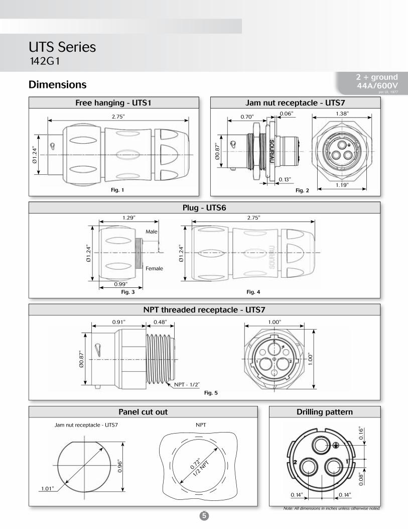
UTS Series142G1
Dimensions
Note: All dimensions in inches unless otherwise noted.
Plug - UTS6
Female
Male
Fig. 3 Fig. 4
1.29" 2.75"
0.99"
Ø1
.24
"
Ø1
.24
"
Free hanging - UTS1
2.75"
Ø1
.24
"
Fig. 1
Jam nut receptacle - UTS7
Fig. 2
0.70"1.38"0.06"
1.19"
Ø0
.87
"
0.13"
Panel cut out
Jam nut receptacle - UTS7
0.9
6"
1.01"
NPT
0.72"
1/2 N
PT
Note: All dimensions in inches unless otherwise noted.
Drilling pattern
0.14" 0.14"
0.0
8"
0.1
6"
NPT threaded receptacle - UTS7
Fig. 5
0.91" 0.48" 1.00"
1.0
0"
Ø0
.87
"2 + ground44A/600V
per UL 1977
NPT - 1/2˝
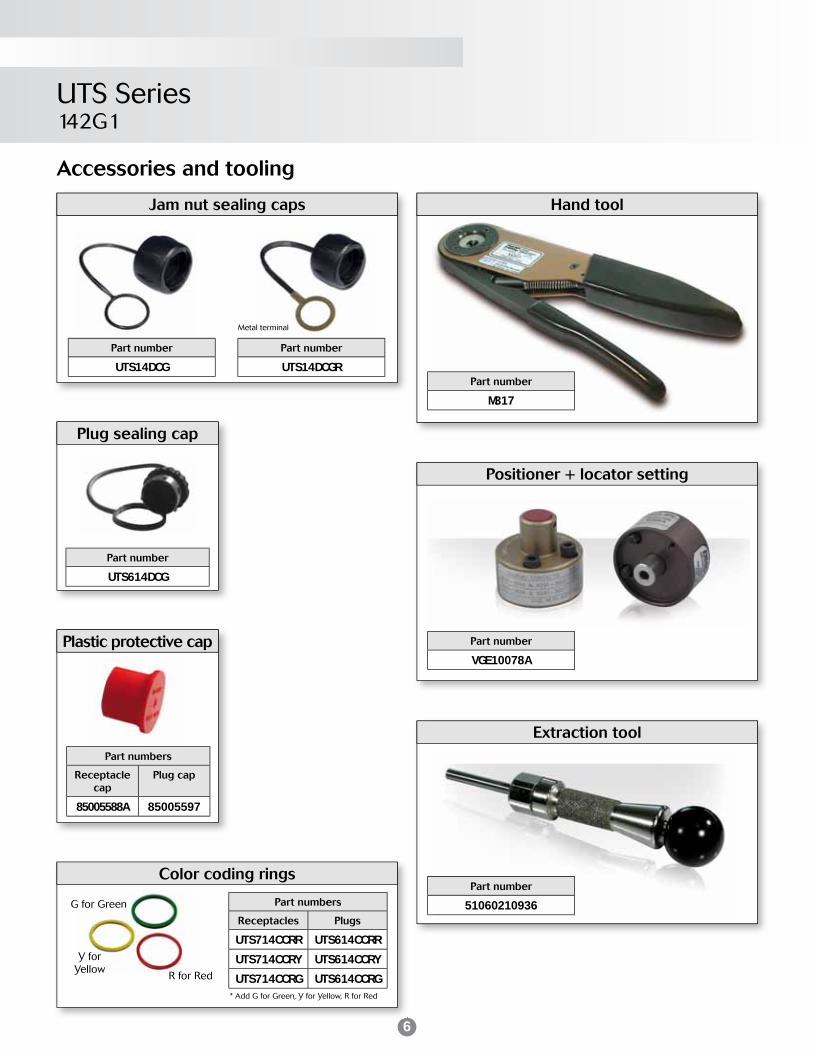
6
UTS Series142G1
Accessories and tooling
Jam nut sealing caps
Metal terminal
Part number
UTS14DCG
Part number
UTS14DCGR
Hand tool
Part number
M317
Positioner + locator setting
Part number
VGE10078A
Extraction tool
Part number
51060210936
Plug sealing cap
Part number
UTS614DCG
Part numbers
Receptacle cap
Plug cap
85005588A 85005597
Plastic protective cap
Color coding rings
* Add G for Green, Y for Yellow, R for Red
Part numbers
Receptacles Plugs
UTS714CCRR UTS614CCRR
UTS714CCRY UTS614CCRY
UTS714CCRG UTS614CCRG
G for Green
Y for Yellow
R for Red

7
UL44A 600V UL94 V-0
CSA30A 600V UL94 V-0
IEC40A 300V 4kV 3
Electrical characteristics UTS 142G1 derating curves
Current use Limited use Not recommended use
UTS Series142G1
Testconditions
Contact used:Machined contactsWires used:8.37mm²
0 20 40 60 80 100 1200
10
15
20
25
30
35
40
45
50
Current (A)
Ambient Operating Temperature (°C)
5
Contacts
#8 Contact type AWGPart number Max
wire Ø (inch)Max
insulator Ø (inch)Male Female
Cri
mp
Machined
16 82913601A(1) 82913600A(1) -
0.25"
14 82913603A(1) 82913602A(1) -
12 82913605A(1) 82913604A(1) -
10 82913607A(1) 82913606A(1) -
8 82913609A(1) 82913608A(1) -
(1): Example of plating, for other plating see page 26
2 + ground44A/600V
per UL 1977
48h sample service

8
WITH
Specifi cations
Contact type Connector type BackshellPart number
Male insert Female insert
Crimp contactssupplied separately
see page 11
NPT threadedreceptacle
Without (Fig.1) UTS7183G1PNPT UTS7183G1SNPT
Plug Without (Fig.2) UTS6183G1P UTS6183G1S
Plug Cable gland (Fig.3) UTS6JC183G1P UTS6JC183G1S
Layoutayout
UTS Series183G1
48h sample service

9
Dimensions
UTS Series183G1
NPT threaded receptacle - UTS7
0.68" 1.25"
1.2
5"
0.57"
NPT - 3/4˝
Ø1
.12
"
Ø0
.77
"
Fig. 1
Plug - UTS6
Fig. 2 Fig. 3
1.48" 3.20"
Ø1
.65
"
Ø1
.65
"
Mated connector length - UTS6JC3.56"
Drilling patternPanel cut0.20" 0.20"
0.2
0"
0.2
0"
3 + ground44A/600V
per UL 1977
NPT
0.92"
3/4 N
PT
Note: All dimensions in inches unless otherwise noted.

10
Accessories and tooling
Metal terminal
* Add G for Green, Y for Yellow, R for Red
G for Green
Y for Yellow
R for Red
UTS Series183G1
Jam nut sealing caps
Part number
UTS18DCG
Part number
UTS18DCGR
Hand tool
Part number
M317
Positioner + locator setting
Part number
VGE10078A
Extraction tool
Part number
51060210936
Part numbers
Receptacle cap
Plug cap
85005590A 85005599
Plastic protective cap
Color coding rings
Part numbers
Receptacles Plugs
UTS714CCRR UTS614CCRR
UTS714CCRY UTS614CCRY
UTS714CCRG UTS614CCRG
Plug sealing cap
Part number
UTS618DCG

11
UL44A 600V UL94 V-0
CSA26A 600V UL94 V-0
IEC32A 300V 4kV 3
Electrical characteristics UTS 183G1 derating curves
Current use Limited use Not recommended use
Testconditions
Contact used:Machined contactsWires used:8.37mm²
UTS Series183G1
1200 20 40 60 80 1000
5
10
15
20
25
30
35
40
45
50
Current (A)
Ambient Operating Temperature (°C)
Contacts
#8 Contact type AWGPart number Max
wire Ø (inch)Max
insulator Ø (inch)Male Female
Cri
mp
Machined
16 82913601A(1) 82913600A(1) -
0.25"
14 82913603A(1) 82913602A(1) -
12 82913605A(1) 82913604A(1) -
10 82913607A(1) 82913606A(1) -
8 82913609A(1) 82913608A(1) -
(1): Example of plating, for other plating see page 26
3 + ground44A/600V
per UL 1977
48h sample service

12
UTS Series106 - 10E6
Specifi cations
OR OR
WITH
OR
Layouty
Contact type Connector type BackshellPart number
Male insert Female insert
Crimp contactssupplied separately
see page 15
Free hangingreceptacle
Cable gland (Fig.1) UTS1JC106P UTS1JC106S
Plug Without (Fig.2) UTS6106P UTS6106S
Plug Cable gland (Fig.3) UTS6JC106P UTS6JC106SJam nut
receptacleWithout (Fig.4) UTS7106P UTS7106S
Hand solderelectrical contacts
loaded
Square fl angereceptacle
Without (Fig.6) UTS010E6P UTS010E6S
PlugWithout (Fig.2) UTS610E6P UTS610E6S
Cable gland (Fig.3) UTS6JC10E6P UTS6JC10E6SJam nut
receptacleWithout (Fig.5) UTS710E6P UTS710E6S
PCB contactssupplied separately
see page 15
Jam nutreceptacle
Without (Fig.4) UTS7106P UTS7106S
Hand solderelectrical contacts
loaded
NPT threadedreceptacle
Without (Fig.7) UTS710E6PM16 UTS710E6SM16
Sealed unmated
OR

NPT threaded receptacle - UTS7
Dimensions
Square fl ange receptacle - UTS0
Fig. 6
Ø0
.59
"
0.09"
0.8
1"
0.94"
Ø0.12"Front view
0.29"
Free hanging - UTS12.75"
Ø0
.59
"
Fig. 1
Plug - UTS6
Female
Male
Fig. 2 Fig. 3
1.29" 2.48"
Ø1
.03
"
Ø1
.03
"
0.99"
Jam nut receptacle - UTS7
0.72"
Ø0
.59
"
0.13" 0.11"
0.48"
Fig. 5
Fig. 4
Front view
0.88"
1.0
7"
Drilling patternPanel cut out
0.7
2"
0.72"
Ø0.12"
0.11"
Ø0.53"
Ø0.86"
Ø0.69"
15°
15°
Ø0.15"
Ø0.12"
0.1
2"
0.0
6"
Square fl ange receptacle - UTS0
Front mountingØ0.59"
Rear mountingØ0.70"
Mated connector length
2.79"
3.04"
UTS7
UTS0
Fig. 7
0.84"
0.54"
Ø0
.59
"
0.19"
0.94"
Jam nut receptacle UTS7
0.6
5"
0.70"
NPT
M16
x1.5
0.77"
Chf.45°x0.10"
M16x1.5
13
UTS Series106 - 10E6
6 contacts6A/250V
per UL 1977
Note: All dimensions in inches unless otherwise noted.

14
UTS Series106 - 10E6
Metal terminal
* Add G for Green, Y for Yellow, R for Red
G for Green
Y for Yellow
R for Red
Jam nut sealing caps
Part number
UTS10DCG
Part number
UTS10DCGR
Plug sealing cap Square fl ange sealing cap
Part number
UTS610DCG
Part number
UTS10DCGE
Part numbers
Receptacle cap
Plug cap
85005586A 85005595
Plastic protective cap
Part numbers / neoprene
UTFD12B
Gasket
Color coding rings
Part numbers
Receptacles Plugs
UTS710CCRR UTS610CCRR
UTS710CCRY UTS610CCRY
UTS710CCRG UTS610CCRG
Accessories and tooling
Metal terminal
Crimp tooling
Contacts Contact sizePart number
of head
RM/RC 24W3K(1)
Standard contacts
#20Ø0.03"
S20RMRM/RC 20W3K(1) S20RMRM/RC 18W3K(1) S20RMSM/SC 24W3S(2) S20SCM20SM/SC 24WL3S(3) S20SCM20SM/SC 20W3S(2) S20SCM20SM/SC 20WL3S(3) S20SCM20
Tool kitHandle
Part number
TOOLKIT
Part number
SHANDLES
(1): Example of plating, for other plating see page 26(2): contact reeled(3): loose contact

15
UTS Series106 - 10E6
6 contacts6A/250V
per UL 1977
Contacts
#20 Contact type AWGPart number Max
wire Ø (inch)Max
insulator Ø (inch)Male Female
Cri
mp
Machined
26-24 RM24W3K(1) RC24W3K(1) - 0.06"
22-20 RM20W3K(1) RC20W3K(1) - 0.06"
20-18 RM18W3K(1) RC18W3K(1) - 0.08"
stamped & formedreeled contacts
26-24 SM24WL3TK6(2) SC24WL3TK6(2) - 0.03"-0.06"
26-24 SM24WL3TK6(2) SC24WL3TK6(2) - 0.03"-0.06"
22-20 SM20WL3TK6(2) SC20WL3TK6(2) - 0.04"-0.08"
22-20 SM20WL3TK6(2) SC20WL3TK6(2) - 0.04"-0.08"
PCB
Machined - RMW5016K RCW5016K - -
(1): Example of plating, for other plating see page 26(2): To obtain contact reeled remove L in part number. Example: SM20M1TK6
IEC7A 32V 1.5kV 3
Electrical characteristics UTS 106 - 10E6 derating curves
Testconditions
Contact used:Machined contactsWires used:0.518mm²
Current use Limited use Not recommended use
0 20 40 60 80 100 1200
4
2
6
8
10
12
14
Current (A)
Ambient Operating Temperature (°C)
UTS 106UL
5A 250V UL94 V-0
CSA4A 250V UL94 V-0
UTS 10E6UL
6A 250V UL94 HB
CSA6A 250V UL94 HB
48h sample service
16
OR
WITH
OR
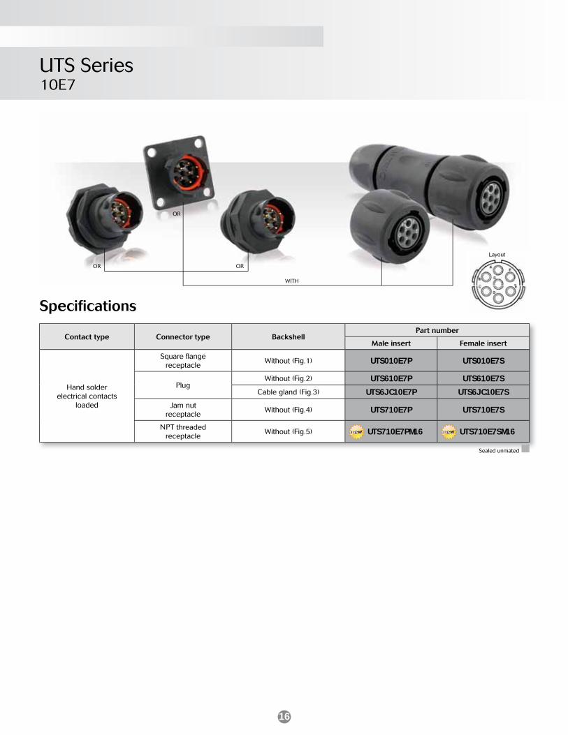
UTS Series10E7
Specifi cations
Contact type Connector type BackshellPart number
Male insert Female insert
Hand solderelectrical contacts
loaded
Square fl angereceptacle
Without (Fig.1) UTS010E7P UTS010E7S
PlugWithout (Fig.2) UTS610E7P UTS610E7S
Cable gland (Fig.3) UTS6JC10E7P UTS6JC10E7SJam nut
receptacleWithout (Fig.4) UTS710E7P UTS710E7S
NPT threadedreceptacle
Without (Fig.5) UTS710E7PM16 UTS710E7SM16
LayoutLayout
Sealed unmated
OR
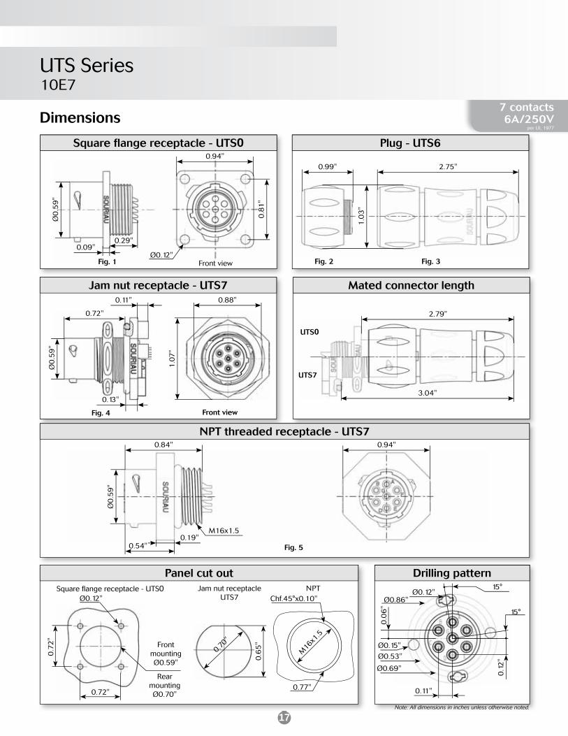
17
UTS Series10E7
Dimensions
Plug - UTS6
Fig. 2 Fig. 3
2.75"
1.0
3"
0.99"
Jam nut receptacle - UTS7
0.72"
0.13"
0.11"
Fig. 4
Ø0
.59
"
Front view
0.88"
1.0
7"
Square fl ange receptacle - UTS0
Fig. 1
Ø0
.59
"
0.09"0.29"
0.8
1"
0.94"
Ø0.12"Front view
Mated connector length
2.79"
3.04"
UTS7
UTS0
Drilling pattern
0.11"
Ø0.53"
Ø0.86"
Ø0.69"
15°
15°
Ø0.15"
Ø0.12"
0.1
2"
0.0
6"
7 contacts6A/250V
per UL 1977
NPT threaded receptacle - UTS7
Fig. 5
0.84"
0.54"
0.94"
M16x1.5
Ø0
.59
"
0.19"
Note: All dimensions in inches unless otherwise noted.
Panel cut out
0.7
2"
0.72"
Ø0.12"Square fl ange receptacle - UTS0
Front mountingØ0.59"
Rear mountingØ0.70"
Jam nut receptacle UTS7
0.6
5"
0.70"
NPT
M16
x1.5
0.77"
Chf.45°x0.10"

18
UTS Series10E7
Metal terminal
* Add G for Green, Y for Yellow, R for Red
G for Green
Y for Yellow
R for Red
Jam nut sealing caps
Part number
UTS10DCG
Part number
UTS10DCGR
Plug sealing cap Square fl ange sealing cap
Part number
UTS610DCG
Part number
UTS10DCGE
Part numbers
Receptacle cap
Plug cap
85005586A 85005595
Plastic protective cap
Part numbers / neoprene
UTFD12B
Gasket
Color coding rings
Part numbers
Receptacles Plugs
UTS710CCRR UTS610CCRR
UTS710CCRY UTS610CCRY
UTS710CCRG UTS610CCRG
Accessories and tooling
Metal terminal
19
UTS Series10E7
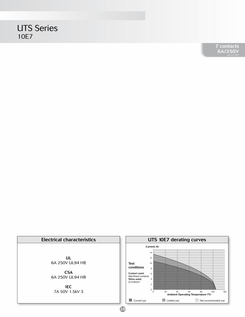
UTS 10E7 derating curvesElectrical characteristics
UL6A 250V UL94 HB
CSA6A 250V UL94 HB
IEC7A 50V 1.5kV 3
Current use Limited use Not recommended use
Testconditions
Contact used:Machined contactsWires used:0.518mm²
0 20 40 60 80 100 1200
6
10
Current (A)
Ambient Operating Temperature (°C)
12
14
2
4
8
7 contacts6A/250V
per UL 1977

20
WITHOR
Specifi cations
Contact type Connector type BackshellPart number
Male insert Female insert
Crimp contactssupplied separately
see page 23
NPT threadedreceptacle
Without (Fig.1) UTS718X2M3PNPT UTS718X2M3SNPT
Plug Without (Fig.2) UTS618X2M3P UTS618X2M3S
Plug Cable gland (Fig.3) UTS6JC18X2M3P UTS6JC18X2M3S
UTS Series18X2M3
Layout
48h sample service

21
Dimensions
UTS Series18X2M3
NPT threaded receptacle - UTS7 0.67" 1.25"
1.2
5"
0.56"
NPT - 3/4˝
Ø1
.12
"
Ø0
.76
"
Fig. 1
Plug - UTS6
Fig. 2 Fig. 3
1.46" 3.20"
Ø1
.55
"
Ø0
.84
"
Ø1
.55
"
Mated connector length - UTS6JC3.56"
Drilling patternPanel cut0.20" 0.20"
0.2
0»
0.2
0"
5 contacts44A/600V
per UL 1977
NPT
0.92"
3/4 N
PT
Note: All dimensions in inches unless otherwise noted.

22
Accessories and tooling
Metal terminal
* Add G for Green, Y for Yellow, R for Red
G for Green
Y for Yellow
R for Red
UTS Series18X2M3
Jam nut sealing caps
Part number
UTS18DCG
Part number
UTS18DCGR
Part numbers
Receptacle cap
Plug cap
85005590A 85005599
Plastic protective cap
Color coding rings
Part numbers
Receptacles Plugs
UTS714CCRR UTS614CCRR
UTS714CCRY UTS614CCRY
UTS714CCRG UTS614CCRG
Plug sealing cap
Part number
UTS618DCG
Crimp tooling #16
Crimp tooling #8
Part number
TOOLKIT
Part numberextraction tool
51060210924
Part number
SHANDLES
Part numberpositioner + locator setting
VGE10078A
Part number hand tool
M317
Contacts Contact sizePart number
of head
RM/RC 28M1K(1)
Standard contacts
#16Ø0.06"
S16RCM20RM/RC 24M9K(1) S16RCM20RM/RC 20M13K(1) S16RCM20RM/RC 20M12K(1) S16RCM20RM/RC 16M23K(1) S16RCM16RM/RC 14M50K(1) S16RCM1450RM/RC 14M30K(1) S16RCM14SM/SC 24ML1TK6(1) S16SCM20SM/SC 20ML1TK6(1) S16SCM20SM/SC 16ML1TK6(1) S16SCML1SM/SC 14ML1TK6(1) S16SCML1SM/SC 16ML11TK6(1) S16SCML11
(1): Example of plating, for other plating see page 26

23
UL44A 600V UL94 V-0
CSA34A 600V UL94 V-0
IEC32A 300V 4kV 3
Electrical characteristics UTS 183G1 derating curves
Current use Limited use Not recommended use
Testconditions
Contact used:Machined contactsWires used:8.37mm²
UTS Series18X2M3
1200 20 40 60 80 1000
5
10
15
20
25
30
35
40
45
50
Current (A)
Ambient Operating Temperature (°C)
Contacts
#8 Contact type AWGPart number Max
wire Ø (mm)Max
insulator Ø (mm)Male Female
Cri
mp
Machined
16 82913601A(1) 82913600A(1) -
0.25"
14 82913603A(1) 82913602A(1) -
12 82913605A(1) 82913604A(1) -
10 82913607A(1) 82913606A(1) -
8 82913609A(1) 82913608A(1) -
5 contacts44A/600V
per UL 1977
#16 Contact type AWGPart number Max
wire Ø (inch)Max
insulator Ø (inch)Male Female
Cri
mp
Machined
30-28 RM28M1K(1) RC28M1K(1) 0.02" 0.04"
26-24 RM24M9K(1) RC24M9K(1) 0.03" 0.06"
22-20 RM20M13K(1) RC20M13K(1) 0.04" 0.07"
22-20 RM20M12K(1) RC20M12K(1) 0.04" 0.08"
20-16 RM16M23K(1) RC16M23K(1) 0.07" 0.12"
16-14 RM14M50K(1) RC14M50K(1) 0.08" 0.12"
16-14 RM14M30K(1) RC14M30K(1) 0.08" 0.12"
Stamped & formedreeled contacts
26-24 SM24ML1TK6(1)(2) SC24ML1TK6(1)(2) 0.03"-0.05" -
22-20 SM20ML1TK6(1)(2) SC20ML1TK6(1)(2) 0.04"-0.08" -
18-16 SM16ML1TK6(1)(2) SC16ML1TK6(1)(2) 0.11" -
18-16 SM16ML11TK6(1)(2) SC16ML11TK6(1)(2) 0.07"-0.11" -
14 SM14ML1TK6(1)(2) SC14ML1TK6(1)(2) 0.12" -
PCB
Machined - RM20M12E8K(1) RC20M12E84K(1) - -
(1): Example of plating, for other plating see page 26(2): To obtain contact reeled remove L in part number. Example: SM20M1TK6 48h sample service
24
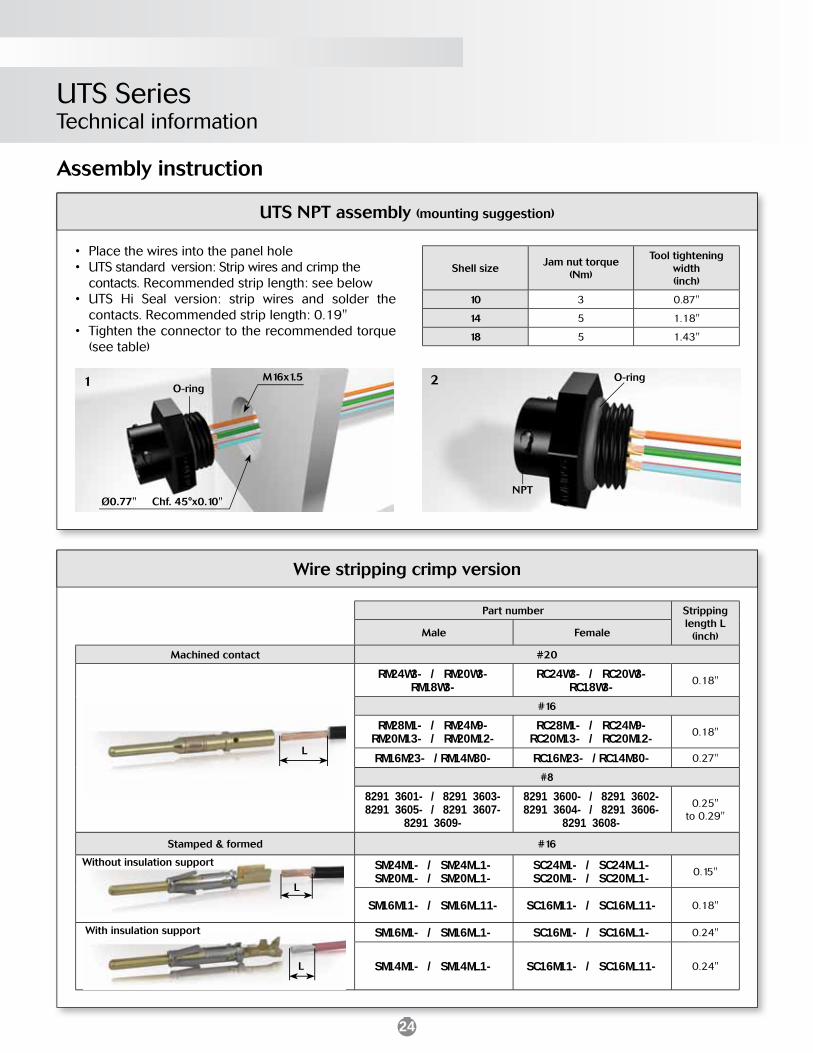
UTS SeriesTechnical information
Shell sizeJam nut torque
(Nm)
Tool tighteningwidth(inch)
10 3 0.87"
14 5 1.18"
18 5 1.43"
• Place the wires into the panel hole• UTS standard version: Strip wires and crimp the contacts. Recommended strip length: see below • UTS Hi Seal version: strip wires and solder the contacts. Recommended strip length: 0.19"• Tighten the connector to the recommended torque (see table)
O-ring
NPT
2O-ring
Ø0.77" Chf. 45°x0.10"
M16x1.51
UTS NPT assembly (mounting suggestion)
Part number Stripping length L
(inch)Male Female
Machined contact #20
RM24W3- / RM20W3-RM18W3-
RC24W3- / RC20W3-RC18W3- 0.18"
#16
RM28M1- / RM24M9-RM20M13- / RM20M12-
RC28M1- / RC24M9-RC20M13- / RC20M12- 0.18"
RM16M23- /RM14M30- RC16M23- /RC14M30- 0.27"
#8
8291 3601- / 8291 3603-8291 3605- / 8291 3607-
8291 3609-
8291 3600- / 8291 3602- 8291 3604- / 8291 3606-
8291 3608-
0.25"to 0.29"
Stamped & formed #16
SM24M1- / SM24ML1-SM20M1- / SM20ML1-
SC24M1- / SC24ML1-SC20M1- / SC20ML1- 0.15"
SM16M11- / SM16ML11- SC16M11- / SC16ML11- 0.18"
SM16M1- / SM16ML1- SC16M1- / SC16ML1- 0.24"
SM14M1- / SM14ML1- SC16M11- / SC16ML11- 0.24"
Assembly instruction
L
L
L
Without insulation support
With insulation support
Wire stripping crimp version
25
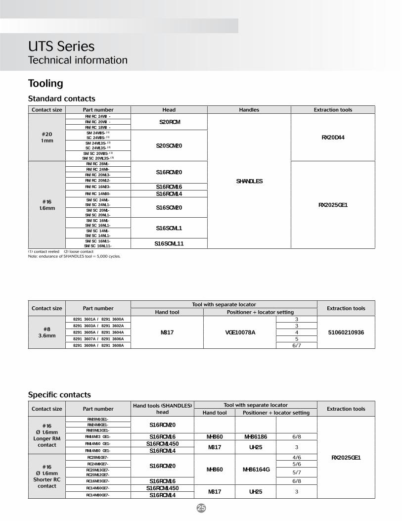
Contact size Part numberTool with separate locator
Extraction toolsHand tool Positioner + locator setting
#83.6mm
8291 3601A / 8291 3600A
M317 VGE10078A
3
510602109368291 3603A / 8291 3602A 38291 3605A / 8291 3604A 48291 3607A / 8291 3606A 58291 3609A / 8291 3608A 6/7
Specifi c contacts
Contact size Part numberHand tools (SHANDLES)
headTool with separate locator
Extraction toolsHand tool Positioner + locator setting
#16Ø 1.6mm
Longer RM contact
RM28M1GE1-
S16RCM20
RX2025GE1
RM24M9GE1-RM20M13GE1-
RM16M23 GE1- S16RCM16 MH860 MH86186 6/8RM14M50 GE1- S16RCM1450 M317 UH25 3RM14M30 GE1- S16RCM14
#16Ø 1.6mm
Shorter RC contact
RC28M1GE7-
S16RCM20 MH860 MH86164G
4/6RC24M9GE7- 5/6RC20M13GE7-RC20M12GE7- 5/7
RC16M23GE7- S16RCM16 6/8RC14M50GE7- S16RCM1450 M317 UH25 3RC14M30GE7- S16RCM14
Tooling
Contact size Part number Head Handles Extraction tools
#201mm
RM/RC 24W3 -
S20RCM
SHANDLES
RX20D44
RM/RC 20W3 -RM/RC 18W3 -SM 24W3S-(1)
SC 24W3S-(1)
S20SCM20SM 24WL3S-(2)
SC 24WL3S-(2)
SM/SC 20W3S-(1)
SM/SC 20WL3S-(2)
#161.6mm
RM/RC 28M1-
S16RCM20
RX2025GE1
RM/RC 24M9-RM/RC 20M13-RM/RC 20M12-
RM/RC 16M23- S16RCM16RM/RC 14M30- S16RCM14SM/SC 24M1-SM/SC 24ML1- S16SCM20SM/SC 20M1-SM/SC 20ML1-SM/SC 16M1-SM/SC 16ML1- S16SCML1SM/SC 14M1-SM/SC 14ML1-SM/SC 16M11-SM/SC 16ML11- S16SCML11
Standard contacts
(1) contact reeled (2) loose contactNote: endurance of SHANDLES tool = 5,000 cycles.
UTS SeriesTechnical information
26
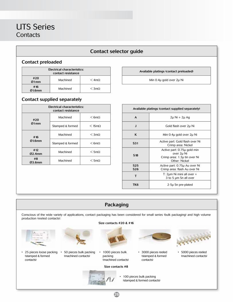
Conscious of the wide variety of applications, contact packaging has been considered for small series (bulk packaging) and high volume production (reeled contacts):
Size contacts #20 & #16
• 100 pieces bulk packing (stamped & formed contacts)
Available platings (contact preloaded)
Min 0.4µ gold over 2µ Ni
Contact preloaded
Contact supplied separately
• 50 pieces bulk packing (machined contacts)
• 25 pieces loose packing (stamped & formed contacts)
• 1000 pieces bulk packing (machined contacts)
• 5000 pieces reeled (machined contacts)
• 3000 pieces reeled (stamped & formed contacts)
Size contacts #8
Contact selector guide
Packaging
UTS SeriesContacts
Electrical characteristics:contact resistance
#20Ø1mm
Machined < 6m
Stamped & formed < 15m
#16Ø1.6mm
Machined < 3m
Stamped & formed < 6m
#12Ø2.4mm
Machined < 5m
#8Ø3.6mm
Machined < 5m
Available platings (contact supplied separately)
A 2µ Ni + 2µ Ag
J Gold fl ash over 2µ Ni
K Min 0.4µ gold over 2µ Ni
S31Active part: Gold fl ash over Ni
Crimp area: Nickel
S18
Active part: 0.75µ gold minover 2µ Ni
Crimp area: 1.3µ tin over NiOther: Nickel
S25S26
Active part: 0.75µ Au over NiCrimp area: fl ash Au over Ni
TT: 2µm Ni mini all over +
3 to 5 µm Sn all over
TK6 2-5µ Sn pre-plated
Electrical characteristics:contact resistance
#20Ø1mm
Machined < 4m
#16Ø1.6mm
Machined < 3m
27
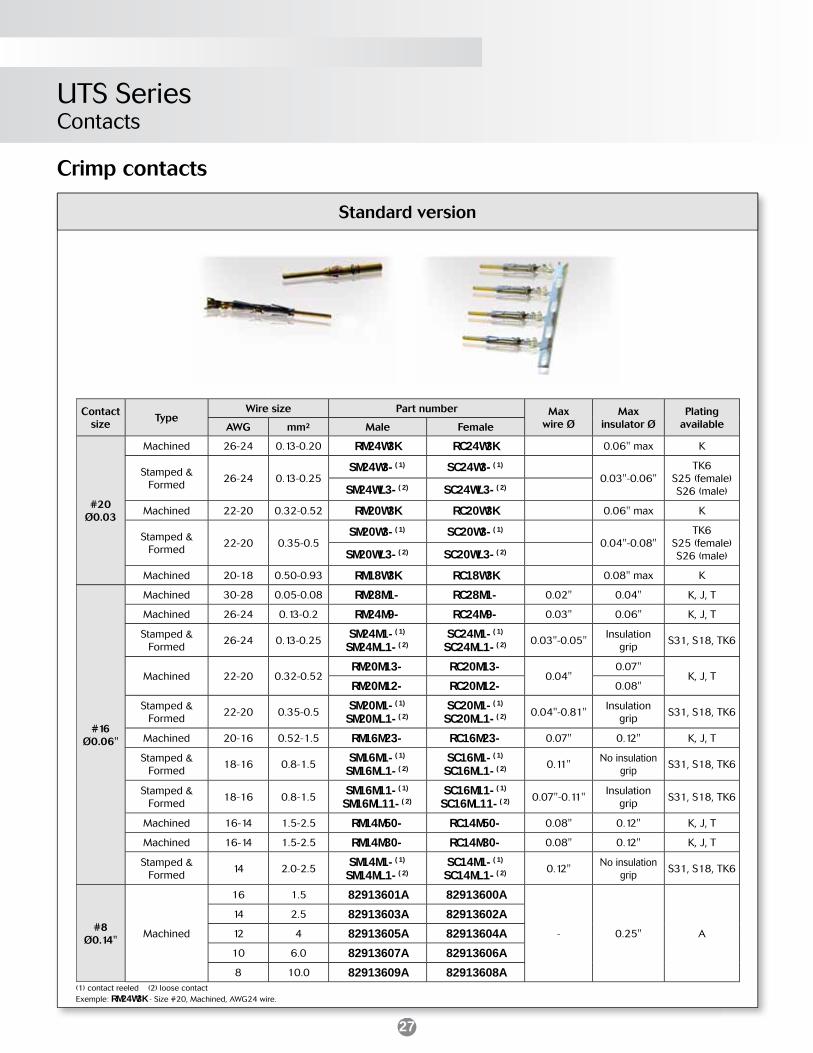
UTS SeriesContacts
Crimp contacts
(1) contact reeled (2) loose contactExemple: RM24W3K - Size #20, Machined, AWG24 wire.
Standard version
Contact size
TypeWire size Part number Max
wire ØMax
insulator ØPlating
availableAWG mm² Male Female
#20Ø0.03
Machined 26-24 0.13-0.20 RM24W3K RC24W3K 0.06" max K
Stamped & Formed
26-24 0.13-0.25SM24W3-(1) SC24W3-(1)
0.03"-0.06"TK6
S25 (female) S26 (male)SM24WL3-(2) SC24WL3-(2)
Machined 22-20 0.32-0.52 RM20W3K RC20W3K 0.06" max K
Stamped & Formed
22-20 0.35-0.5SM20W3-(1) SC20W3-(1)
0.04"-0.08"TK6
S25 (female) S26 (male)SM20WL3-(2) SC20WL3-(2)
Machined 20-18 0.50-0.93 RM18W3K RC18W3K 0.08" max K
#16Ø0.06"
Machined 30-28 0.05-0.08 RM28M1- RC28M1- 0.02" 0.04" K, J, T
Machined 26-24 0.13-0.2 RM24M9- RC24M9- 0.03" 0.06" K, J, T
Stamped & Formed
26-24 0.13-0.25 SM24M1-(1)
SM24ML1-(2)SC24M1-(1)
SC24ML1-(2) 0.03"-0.05"Insulation
gripS31, S18, TK6
Machined 22-20 0.32-0.52RM20M13- RC20M13-
0.04"0.07"
K, J, TRM20M12- RC20M12- 0.08"
Stamped & Formed
22-20 0.35-0.5 SM20M1-(1)
SM20ML1-(2)SC20M1-(1)
SC20ML1-(2) 0.04"-0.81"Insulation
gripS31, S18, TK6
Machined 20-16 0.52-1.5 RM16M23- RC16M23- 0.07" 0.12" K, J, T
Stamped & Formed
18-16 0.8-1.5 SM16M1-(1)
SM16ML1-(2)SC16M1-(1)
SC16ML1-(2) 0.11"No insulation
gripS31, S18, TK6
Stamped & Formed
18-16 0.8-1.5 SM16M11-(1)
SM16ML11-(2)SC16M11-(1)
SC16ML11-(2) 0.07"-0.11"Insulation
gripS31, S18, TK6
Machined 16-14 1.5-2.5 RM14M50- RC14M50- 0.08" 0.12" K, J, T
Machined 16-14 1.5-2.5 RM14M30- RC14M30- 0.08" 0.12" K, J, T
Stamped & Formed
14 2.0-2.5 SM14M1-(1)
SM14ML1-(2)SC14M1-(1)
SC14ML1-(2) 0.12"No insulation
gripS31, S18, TK6
#8Ø0.14"
Machined
16 1.5 82913601A 82913600A
- 0.25" A
14 2.5 82913603A 82913602A
12 4 82913605A 82913604A
10 6.0 82913607A 82913606A
8 10.0 82913609A 82913608A

28
Industry
Stage - Light
Off road - MiningRailway
Building automation & control
Medical
Connection Technologies
WIN
DU
TGO
01
US
© C
opyr
ight
SO
UR
IAU
2012
- A
ll in
form
atio
n in
thi
s do
cum
ent
pres
ents
onl
y ge
nera
l par
ticul
ars
and
shal
l not
form
par
t of
any
con
trac
t. A
ll rig
hts
rese
rved
to
SOU
RIA
U fo
r ch
ange
s w
ithou
t pr
ior
notifi
cat
ion
or p
ublic
ann
ounc
emen
t. A
ny d
uplic
atio
n is
pro
hibi
ted,
unl
ess
appr
oved
in w
ritin
g.UTS Series


![POWERMAX [ˈpou (ə)r ˈmaks] noun: a system designed to ...sites.ieee.org/houston/files/2016/10/05_SPS_PMS_SimulatorMotorMAX.… · SEL-849. Eliminate Hard Wiring With One Ethernet](https://img.dokumen.tips/doc/110x75/5a8536777f8b9a87368c9f02/powermax-pou-r-maks-noun-a-system-designed-to-sitesieeeorghoustonfiles20161005spspmssimulatormotormaxsel-849.jpg)