Embed Size (px)
Citation preview

Project Number: F7N24949 Page 1 of 22 Project Name: RED Lion
Date: 09-20-2013 Customer Signature:
Elevator Approval - Gen2-150
Submitted By: Otis Elevator Company 2788 Rupert Street Vancouver, British Columbia V5M 3T7 Prepared by: Cory Madden Phone: 604-412-3400 Fax: (604) 438-5111
For Project: RED Lion
North Vancouver, British Columbia
Six (6) Sets of Approvals Submitted ~ Return two (2) sets to Otis ~ Retain one (1) set on Job Site ~ Disburse remaining three (3) sets to the; General Contractor, Architect, Owner
09/20/2013
Date Submitted Approval Signature
10/01/2013
Required Return Date Date Returned
Architect's Approval Stamp
Performance Construction Ltd. 213 - 21300 Gordon Way - Unit 213 Richmond, British Columbia V6W 1M2 Phone: 604-628-9619 Fax:

Project Number: F7N24949 Page 2 of 22 Project Name: RED Lion
Date: 09-20-2013 Customer Signature:
Critical Construction information
Comments: We are pleased you have selected Otis Elevator Company for your upcoming project. In order for on time installation of
your elevator(s), please provide the information and requirements requested above.
Customer: Performance Construction Ltd.
213 - 21300 Gordon Way - Unit 213
Richmond, British Columbia V6W 1M2
Project: RED Lion
North Vancouver, British Columbia
Phone: Fax:
Invoicing Information Please advise as to the date invoices must reach your office each month to be processed in a timely manner. Invoices are due on the of each month.
Job Site Information Name of Superintendent: _____________________________________Phone #: _____________________. Driving Directions: _______________________________________________________________________________ ______________________________________________________________________________________________________________________________________________________________________________________________
Please provide the following dates Date you would like elevator material delivered .
Date elevator installation to be completed by .
Notes:
Changes to delivery dates must be made twelve (12) weeks prior to the material delivery dates shown above. Delivery date changes requested
with less than twelve weeks notice may result in additional costs. Consult your Otis Representative.
Job-site must be ready for installation when material is delivered (see below for details). If the site is not ready when material arrives, the material needs to be placed inside the building in a dry, safe area. Contractor must provide roll-able access to move material from the truck into the building, provide a forklift and an operator to move material at no cost to Otis. If the material cannot be stored inside the building, you will be
required to pay for additional handling and/or storage until the building is ready. If the material is not stored in a dry, safe place, or outside exposed to the elements, Otis is not liable for any damages to the material, and you will be required to pay for any necessary repairs or replacements.
Provide sufficient on-site refuse containers for the proper disposal of elevator packaging material. Should sufficient refuse containers not be provided, packaging material shall become the responsibility of the owner.
If Otis is directed in writing to install elevator equipment early (such as rails), and building is exposed to the weather, there is a possibility of rust forming on the equipment. If fireproofing is applied, there is a possibility it will adhere to our equipment. Should clean up be required for either
fireproofing or rust formation, it will be charged to the General Contractor.
The following must be provided, by others, prior to Otis manning the job-site 1. 3-Phase Power and Disconnect per Confirmation of Power Form 2. Hoistway, Pit, and Machine Room dry & clean 3. Storage space close to elevator with roll-able access 4. Inserts and fastenings provided per our approval package 5. Freestanding Removable Barricades 6. OSHA approved fall protection at the top of the hoistway is in place.

Project Number: F7N24949 Page 3 of 22 Project Name: RED Lion
Date: 09-20-2013 Customer Signature:
Confirmation of Three Phase Power Supply
Gen2™ Series with Regenerative Drive, Elevator System
Performance Construction Ltd.
213 - 21300 Gordon Way - Unit 213
Richmond, British Columbia V6W 1M2
Otis Canada Inc. 2788 Rupert Street
Vancouver, British Columbia V5M 3T7
Contact: Cory Madden Phone: 604-412-3400 , Fax: (604) 438-
5111
Project: RED Lion
North Vancouver, British Columbia
NOTE: Manufacture will not be started until the owner or the owner's representative signs and returns this form to Otis Canada Inc.. This form must be completed, signed and returned by to meet the scheduled completion date of .
Part A. POWER CONFIRMATION The power supply requirements are as indicated below. You are requested to verify (or correct) this information and confirm its accuracy by your signature in the space provided. Should a change in the information provided subsequently occur, immediate notification of the change is necessary.
1. 600 volts,, three phase, 60 hertz and a separate equipment-grounding conductor (Ref: Canadian Electrical Code C22.1). (Note: Grounding at points other than system neutral is not permitted). The three phase electrical system for the elevators must contain balanced phase voltages when referenced to system neutral. If other than a balanced three-phase system is provided please notify Otis immediately.
2. Car lighting: 125 volt, single-phase, 15 ampere, 60 hertz dedicated branch circuit.
Voltage variations for power supplies to be within 10% of nominal supply voltage indicated in item (1) above. Frequency variations to
be within 2 Hertz. If voltage or frequency variation does not fall within these limits, please give details.
The above power-supply characteristics are confirmed.
SIGNED BY: __________________________________ DATE: ________________
Part B. ELECTRICAL REQUIREMENTS (See CEC)
1. Elevator controller terminations for three phase wiring are rated for 75 C. (SaRefG2S.docx#CanadaCode2)Elevators supplied to this document are rated at 10,000 Amps RMS Symmetrical Short Circuit Current (SCCR).
2. Elevator Feeder Short Circuit protection by others shall limit the Available Short Circuit Current (ASCC) at the elevator control equipment to 10,000 Amps maximum symmetrical RMS.
3. The data provided in Part C are based upon the power supply as noted in Part A. 4. The elevator system power total current harmonic distortion is less than 8% and the power factor is 95% or greater. 5. To assist you in the planning for the elevator installation requirements to be provided by other trades prior to the installation of
our equipment, we are pleased to supply the: a. Electrical data required for the elevator system are detailed in Part C through Part F. b. Elevator system interface requirements to interface to other building required options detailed in Part G through
Part J.
Master file: AAA29000AN_PWR_CONF.zip
REV 9/11/2012- TDA Master file: AAA29000AN_PWR_CONF.zip
REV 9/11/2012- TDA

Project Number: F7N24949 Page 4 of 22 Project Name: RED Lion
Date: 09-20-2013 Customer Signature:
Confirmation of Three Phase Power Supply
Gen2™ Series with Regenerative Drive, Elevator System Part C. Elevator AC Line Current data below are based on the Power Supply Information provided in Part A
ELEVATOR NAME OR NUMBER
ELEVATOR CONTRACT
NUMBER DUTY
CAR SPEED
REFER TO CSA Standard C22.1, Canadian Electrical Code – Part 1
MOTOR CONTROLLER NAMEPLATE
CURRENT RATING With Elevator Running
Full Load Up
FULL LOAD UP ACCELERATING
CURRENT
Unit 1 TBD 2500 200 13 15
Unit 2 TBD 2100 200 11 14
Part D. ELEVATOR REGENERATIVE POWER REQUIREMENTS
The regenerated power complies with IEEE 1547
ELEVATOR NAME OR
NUMBER
ELEVATOR CONTRACT
NUMBER
ELEVATOR RUNNING FULL LOAD
DOWN AMPS
ELEVATOR RUNNING FULL LOAD DOWN kW
ELEVATOR STOPPING FULL LOAD
DOWN AMPS
ELEVATOR STOPPING FULL LOAD DOWN kW
Unit 1 TBD 8 6.128 9 7.355
Unit 2 TBD 6 4.777 8 6.408
TOTALS
Master file: AAA29000AN_PWR_CONF.zip
REV 9/11/2012- TDA

Project Number: F7N24949 Page 5 of 22 Project Name: RED Lion
Date: 09-20-2013 Customer Signature:
Confirmation of Three Phase Power Supply
Gen2™ Series with Regenerative Drive, Elevator System
Part E. ELECTRICAL REQUIREMENTS
Elevator Management System (EMS) - a dedicated 125 volt 20 ampere single-phase power supply with SPST disconnect
switch or circuit breaker with duplex outlets per Otis layout, and at any location where a Security Station and/or Fire Station is furnished.
Car Air Conditioning & Heating - a dedicated branch circuit with suitable characteristics to power car heating and air conditioning provided by others. (Special contracting required, contact your local Otis sales representative)
X Prior to the start of installation provide for each elevator the following: 1. A permanent three (3) phase electrical-feeder system with a separate equipment grounding conductor terminating
in the elevator control equipment located per Otis layout. 2. Feeder conductors and grounding conductor sized according to elevator current characteristics as shown on the
Otis Confirmation of Power Supply form. 3. Feeder and grounding conductors must be copper. 4. A fused disconnect switch or circuit breaker capable of being locked in the open position for each elevator located
upstream of the elevator equipment per the (Canadian Electrical Code (C22.1)) a. The disconnecting means required by the (Canadian Electrical Code CEC [Rule 38-051] and [Rule
38013(2)(a)) shall be provided with all associated wiring and conduit to the elevator equipment. b. Size of main contacts to suit elevator power characteristics c. Fuses, if provided, are to be current limiting class J or equivalent, see Part B for elevator equipment
SCCR d. Circuit breakers, if provided, are to have current limiting characteristics equivalent to class J fuses, see
Part B for elevator equipment SCCR 5. Fuses or circuit breakers are to be time delay to cover the full load up accelerating current as listed in Part B
above. 6. Feeder conductors and associated wiring to the controller to be sized to limit wiring voltage drop to 5% maximum
when delivering elevator full load up accelerating current.
X In addition, when the Automatic Return Unit (ARU) is specified, the mainline fused disconnect switch or circuit breaker shall be equipped with an auxiliary contact that is positively opened when the main line disconnect is in the OFF position. Fused disconnect located as required.
X Provide a dedicated 125 volt, 15 ampere single-phase branch circuit, with a fused disconnect switch or circuit breaker. The fused disconnect or circuit breaker shall be capable of being locked in the open position and located upstream of the elevator equipment. This branch circuit supplies the car lights, car top receptacle, auxiliary lighting power source and ventilation on each car in compliance with the CEC [Rule 38-053]
X All 125 volt, 15 or 20 ampere single-phase receptacles required installed in pits, machine spaces, shall be of the ground-fault circuit-interrupter type (GFCI). A dedicated single-phase receptacle supplying a permanently installed pit sump pump shall not require GFCI protection.
X Provide electric power for lights, tools, welding, hoisting, etc. during installation with sufficient power for starting, testing and adjusting the elevator. Provide a 220 volt, 30 ampere single-phase 4 wire electrical supply for platform operation during construction, available at the start of elevator installation.
X The building power system used to operate the elevator(s) shall be capable of supplying non linear loads and be capable of absorbing the regenerated power contained in the table in the Part D “ELEVATOR REGENERATIVE POWER REQUIREMENTS” to comply with ASME A17.1/CSA B44 Rule 2.26.10 and Rule 2.27.2.5. The information, contained in the table, is to be used to determine regenerative power absorption capability for the building normal power distribution system.
Master file: AAA29000AN_PWR_CONF.zip
REV 9/11/2012- TDA

Project Number: F7N24949 Page 6 of 22 Project Name: RED Lion
Date: 09-20-2013 Customer Signature:
Confirmation of Three Phase Power Supply
Gen2™ Series with Regenerative Drive, Elevator System
Part F. EMERGENCY (STANDBY) POWER REQUIREMENTS
For installations having emergency (standby) power, provide the standby power unit and means for starting it. The
emergency (standby) power unit shall deliver via disconnect switches in the control room/space, sufficient power to operate one or more elevators at a time at full rated speed, and rated load.
An automatic power transfer switch for each power feeder to monitor both normal and emergency (standby) power conditions and to perform the transfer from one to the other. Switch to have two sets of normally closed dry contacts, one to be open when the switch is in the emergency (standby) power position; the other to open upon initiation of power transfer and to close when transfer is complete. Switch to have an inhibit function which will delay transfer to normal and/or emergency (standby) power by an adjustable period of 0 – 300 seconds. Switch shall have a phase monitor feature, which prohibits the transfer of power between “live” sources unless the sources are in phase with each other. If a shunt trip device is provided, an additional normally closed contact, with all associated wiring and conduit to the controller, is required from the emergency (standby) power source. The emergency (standby) power system provided shall comply with C22.1-06 Canadian Electrical Code, Part I, 38-091
The table in Part D “ELEVATOR REGENERATIVE POWER REQUIREMENTS” contains the elevator system power regenerated under an overhauling load. The information contained in the table is to be used to determine regenerative power absorption capability for the emergency (standby) power distribution system.
Note: The building Emergency (Standby Power) Generator system used to operate the elevator(s) shall be
capable of supplying non-linear loads.
Emergency (standby) power system shall also be connected to the 125 volt branch circuit supplying power to the car lights, car top receptacle, auxiliary car lighting power source and car ventilation as noted in Part A.2 of the Power Supply Confirmation Form
Master file: AAA29000AN_PWR_CONF.zip
REV 9/11/2012- TDA

Project Number: F7N24949 Page 7 of 22 Project Name: RED Lion
Date: 09-20-2013 Customer Signature:
Confirmation of Three Phase Power Supply
Gen2™ Series with Regenerative Drive, Elevator System
Part G. COMMUNICATION REQUIREMENTS
X Provide one (1) dedicated outside analog telephone line per elevator car terminated at the elevator controller. The
telephone line must meet the following requirements: Loop Current: Min 20mA, Max 120mA Nominal AC Line Impedance = 600 ohms Line Voltage: On Hook – Min 15Vdc, Max 56.5Vdc Ring Voltage: Min 40Vac(rms), Max 150Vac(rms) Off Hook – Min 8.75Vdc Ring Frequency: 15-68Hz
Separate 125 volt, 15 ampere single-phase power supply with fused SPST disconnect switch or circuit breaker, located as required for inter-communicating system power supply. Circuit to be arranged for feeding from the building emergency lighting supply if provided. Conduit and wiring for remotely located inter-communicating stations.
Part H. SMOKE DETECTOR REQUIREMENTS
Provide smoke detectors, located as required, with wiring from the sensing devices to the controller(s) designated by Otis.
I. For each group of elevators, provide a normally closed contact representing the smoke detector at the designated return landing.
II. For each group of elevators, provide a normally closed contact representing all smoke detectors located in lobbies and hoistways, but not the smoke detector at the designated return landing (see above) or the smoke detectors as described in a) below:
a) If a smoke detector is located in the hoistway at or below the lower of the two recall landings, it shall be wired to activate the same normally closed contact as the smoke detector located in the lobby at the lower of the two recall landings.
III. Requirements for intermittently illuminating the fire hat visual signal in the car operating panel, either a) or b) must be selected.
a) For a single unit, or group of elevators having one common hoistway, provide one additional normally closed contact representing the control room/space and hoistway smoke detectors.
b) If the group contains more than one hoistway, and hoistway smoke detectors are installed, provide one normally closed contact for each elevator. The contact is to represent the smoke detectors in the hoistway containing that particular elevator.
Part 1 -
Part I. SPRINKLER REQUIREMENTS
X If sprinklers are installed in the hoistway(s), or machine space(s), a means to automatically disconnect the main line power
supply of the affected elevator(s) prior to the application of water is required.
X In addition, when the Automatic Return Unit (ARU) is specified, the means provided to automatically disconnect power to the elevator shall be equipped with an additional auxiliary contact that is positively opened when power is removed from the elevator system. The automatically controlled mainline disconnect must be provided with all associated wiring and conduit to the controller.
Master file: AAA29000AN_PWR_CONF.zip
REV 9/11/2012- TDA

Project Number: F7N24949 Page 8 of 22 Project Name: RED Lion
Date: 09-20-2013 Customer Signature:
Confirmation of Three Phase Power Supply
Gen2™ Series with Regenerative Drive, Elevator System
Part J. HEATING, VENTILATION, AIR CONDITIONING REQUIREMENTS
X Machinery/Control Space, Machine/Control Room –
1. Maintain the temperature in the machinery/control space or Machine/Control Room between 32º F (0º C) and 104º F (40º C). a. machinery/control space located at the top of the hoistway includes the elevator control equipment, i.e. controller,
transformer, and drive. 2. Relative humidity shall not exceed 95% non-condensing. 3. Provide ventilation to suit Otis heat release amounts as shown in the table below. Local codes may require tighter
temperature ranges and higher ventilation levels. Please check with your local code authority for the exact requirements in your area.
Control Room/Space
ELEVATOR NAME OR
NUMBER
ELEVATOR
CONTRACT NUMBER DUTY
HEAT RELEASE PER
CAR (BTU/HR)
Unit 1 TBD 2500 5000
Unit 2 TBD 2100 4800
TOTAL BTU’s
Machine Space
ELEVATOR NAME OR NUMBER
ELEVATOR CONTRACT NUMBER
DUTY HEAT RELEASE PER
CAR (BTU/HR)
Unit 1 TBD 2500 2100
Unit 2 TBD 2100 1900
TOTAL BTU’s
Master file: AAA29000AN_PWR_CONF.zip
REV 9/11/2012- TDA

Project Number: F7N24949 Page 9 of 22 Project Name: RED Lion
Date: 09-20-2013 Customer Signature:
ELEVATOR HOISTWAY APPROVAL DATA
Group 1 - Unit 1- Landing Designations and Floor Heights
Front Designations Distance Between Floors
Pit 4 ft 0 in 0
P2
P1
1
2
3
4
5
9 ft 8 in 0
9 ft 3 in 0
13 ft 0 in 0
9 ft 2 in 0
9 ft 2 in 0
9 ft 2 in 0
0 ft 0 in 0
Overhead 12 ft 11 in 0
Total Rise: 59 ft 5 in 0
Sprinkled Hoistway – If sprinkler system is installed in the hoistway, weatherproof (NEMA4-Traction only) equipment and wiring will be provided in the pit by Otis to comply with ASME A17.1 102.2 (c) 5 (a) & (b).
Product Confirmation
Please sign the attached approval layout in the space provided confirming the dimensions, opening arrangement, coordination notes, etc., shown therein.
Firefighter’s Service Operation (Required by ASME A17.1)
We will provide phase I & II control provisions. You must provide the Phase I designated floor designation (egress) that the elevator will return to in event of fire, as well as an alternate floor designation which the elevator will park at in the event that the fire is a the designated landing. The egress landing is the floor level that occupants of the building will exit at in case of fire.
Designated Phase I Stop: _________
Alternate Phase I Stop is: ________
Select Main Egress Designated Stop/opening: __________ (may differ from Designated Phase 1 stop)
Changing the Phase 1 designated egress, Phase 1 alternate egress, or Main egress landings after the elevator is ordered will cost a minimum $500 extra to cover software changes, Braille markings, and floor markings.
The above landing designations are confirmed.
SIGNED BY: __________________________________ DATE: ________________

Project Number: F7N24949 Page 10 of 22 Project Name: RED Lion
Date: 09-20-2013 Customer Signature:
Entrance Door, Frame, and Sill Finish per Floor
Front Marking Front
Hoistway Frame Finish
Front Hoistway Door
Finish
Front Sill Finish
P2
P1
1
2
3
4
5
Real White (Prime)
Real White (Prime)
Stainless Steel Full #4
Real White (Prime)
Real White (Prime)
Real White (Prime)
Real White (Prime)
Real White (Prime)
Real White (Prime)
Stainless Steel Full #4
Real White (Prime)
Real White (Prime)
Real White (Prime)
Real White (Prime)
Aluminum
Aluminum
Aluminum
Aluminum
Aluminum
Aluminum
Aluminum
Revised 10/5/2012- TDA

Project Number: F7N24949 Page 11 of 22 Project Name: RED Lion
Date: 09-20-2013 Customer Signature:
Masonry Entrances- Machine Roomless
LANDING FRAME DEPTH M1 WALL THICKNESS M2 WALL THICKNESS M3
“F” = IN/mm “W” = IN/mm “W” = IN/mm
“F” = IN/mm “W” = IN/mm “W” = IN/mm
“F” = IN/mm “W” = IN/mm “W” = IN/mm
“F” = IN/mm “W” = IN/mm “W” = IN/mm
“F” = IN/mm “W” = IN/mm “W” = IN/mm
“F” = IN/mm “W” = IN/mm “W” = IN/mm
“F” = IN/mm “W” = IN/mm “W” = IN/mm
Sills: Aluminum or Bronze
F = Total slide-jamb depth W = Total wall thickness at entrance (actual; not nominal)
Entrance Frame Height= 84 inches Notes: 1-All frames are bolted. Frame heads project 1/4” (6mm) beyond front face of side jamb.
All jamb faces (head and sides) are 2-7/8” (73 mm). 2. Embossed handicapped plates measuring 4” x 4” (102 mm x 102 mm) are applied to both jambs of each entrance at appropriate height, characters are 2” (51 mm) high and raised with adjacent Braille.
3. Opening type and size are per cab selection. Entrances arranged for flush sill support per layout “Detail A.” 4. Sight guards are black with all doors. 5. Arrangement M1, M2, and M3 have a 1-1/2” hour fire protection rating.
6. Controller entrance must be the landing at the top terminal front opening. The minimum wall depth at this landing is 8” for M1, and 7” for M2 or M3.
Arrangement M1 Recessed frame in masonry wall.
Arrangement M2 Unfinished masonry wall, or Masonry with furred drywall
Arrangement M3 - Masonry with plaster finish Top Landing Entrance Requirements (MRL only)
Must be located @ the Front Top Entrance
Comments:
SA Masonent.dot REV 07/2008
W
F
4.81" Min.20.00" Max. X
X
W
GYPSUM WALLBOARD(OPTIONAL)
5/8"
METAL ORWOOD FURRING(OPTIONAL)
3.45" Min.18.18" Max.
3.5” Min.
18.37” Max.
X
W
1/2"
3.45" Min.18.18" Max.
PLASTER FINISH
3.5 Min.
18.37 Max

Project Number: F7N24949 Page 12 of 22 Project Name: RED Lion
Date: 09-20-2013 Customer Signature:
Raised Laminate Panel Passenger Cab - Unit 1
Front Only, Single Slide Doors, Flat Metal Ceiling Panel Arrangements
Vertical Raised Laminate Panel panels- 5 back and 3 side with Black Trim Base pieces, located at top and bottom of the cab, are constant features. Base has a Brushed Steel Finish.
Shown With
Optional Handrails
Fascia & Return
Finish
Brushed Stainless
Steel Cab H: 7 ft 9 in W: 6 ft 5 in 9/16 D: 4 ft 3 in 9/16
Car Door Finish Brushed Stainless
Steel Floor Recess- 1 in 1/4 Material By Others
Threshold Finish Extruded Aluminum Exhaust Fan 1 Speed
Opening H: 7 ft W: 3 ft 6 in Laminate Select from separate attachment
saCABS.docx#GeneralCab REV 8/15/2012- TDA
Single Slide Door
Left Hand
Right Hand

Project Number: F7N24949 Page 13 of 22 Project Name: RED Lion
Date: 09-20-2013 Customer Signature:
Raised Laminate Panel Passenger Cab - Unit 2
Front Only, Single Slide Doors, Flat Metal Ceiling Panel Arrangements
Vertical Raised Laminate Panel panels- 5 back and 3 side with Black Trim Base pieces, located at top and bottom of the cab, are constant features. Base has a Brushed Steel Finish.
Shown With
Optional Handrails
Fascia & Return
Finish
Brushed Stainless
Steel Cab H: 7 ft 9 in W: 5 ft 8 in 5/16 D: 4 ft 3 in 9/16
Car Door Finish Brushed Stainless
Steel Floor Recess- 1 in 1/4 Material By Others
Threshold Finish Extruded Aluminum Exhaust Fan 1 Speed
Opening H: 7 ft W: 3 ft Laminate Select from separate attachment
saCABS.docx#GeneralCab REV 8/15/2012- TDA
Single Slide Door
Left Hand
Right Hand

Project Number: F7N24949 Page 14 of 22 Project Name: RED Lion
Date: 09-20-2013 Customer Signature:
Ceiling FC4 - - Unit 1-2
Flat Metal Ceiling with 4 LED Lights
Ceiling Finish: Brushed Steel Finish

Project Number: F7N24949 Page 15 of 22 Project Name: RED Lion
Date: 09-20-2013 Customer Signature:
DH-156 Handrails - - Unit1- 2
1 ½” dia (38.1 mm) Round Bar handrail Brushed Steel Finish
Side and Rear

Project Number: F7N24949 Page 16 of 22 Project Name: RED Lion
Date: 09-20-2013 Customer Signature:
CAR FIXTURE - - Unit 1-2
In Car Direction Lantern
Blue LED Illumination
Characters and “Fishtail” Braille Markings are compliant with the
Americans with Disabilities Act and ANSI A1 17.1
Single Slide Arrangement (Right Hand Shown)
Center Opening Arrangement

Project Number: F7N24949 Page 17 of 22 Project Name: RED Lion
Date: 09-20-2013 Customer Signature:
CAR FIXTURE – continued- - Unit 1-2
Emergency Light
Blue, 2 digit position/car direction indicator
Data Plate- Text varies by contract
Optional operating features are included in this module. Exact arrangements vary accordingly
Optional “NO SMOKING UNDER PENALTY OF LAW” applied label
White raised characters and symbols on black background
Braille
Floor markings vary
FINISH Brushed Steel Car Operating Panel
IN-CAR LANTERN In-car direction lanterns are furnished in each return column- One per opening
NOTE ASME A17.1-1990 requires the car number to appear on the car operating panel if there are two or more elevators in the same hoistway or machine room

Project Number: F7N24949 Page 18 of 22 Project Name: RED Lion
Date: 09-20-2013 Customer Signature:
Standard Hall Fixtures
Hall Button Fixtures
Lobby Intermediate Terminal
Faceplate Satin Stainless Steel or Gold Satin Finish (Typical fixtures shown, will vary by options selected)
Buttons
Flush Mount Projecting Vandal Resistant Lexan
Blue Plastic LED Illuminated Halo, Satin Stainless Steel or Gold Satin Finish
Hall Lantern
Hall Position Indicator
LCD Screen – Satin Stainless Steel or Gold Satin Finish

Project Number: F7N24949 Page 19 of 22 Project Name: RED Lion
Date: 09-20-2013 Customer Signature:
Group 1- Gen2 Elevator System - [!:%::.ALIKE_UNIT_NAMES:!]
Front Floor Marking
Front Hall Fixture Finish
P2
P1
1
2
3
4
5
Stainless Steel Full #4
Stainless Steel Full #4
Stainless Steel Full #4
Stainless Steel Full #4
Stainless Steel Full #4
Stainless Steel Full #4
Stainless Steel Full #4
Brushed Steel Hall Position Indicators at 1
Project Number: F7N24949 Page 20 of 22 Project Name: RED Lion
Date: 09-20-2013 Customer Signature:
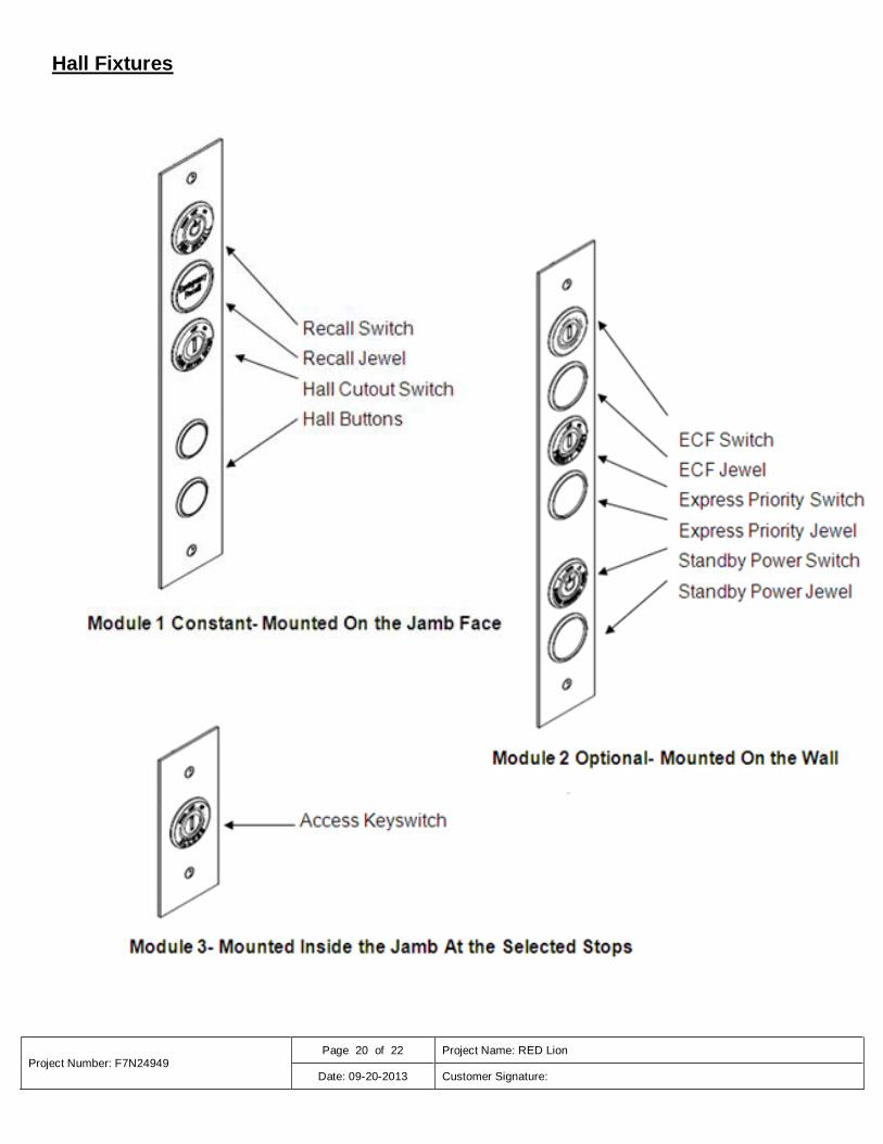
Hall Fixtures

Project Number: F7N24949 Page 21 of 22 Project Name: RED Lion
Date: 09-20-2013 Customer Signature:
SUGGESTED BARRICADING METHODS
SA Barricad.dot REV 8/2001
#1 #2
#3
Barricades Must Meet OSHA Minimum Requirements
42” high
Have center board and kick board
Must withstand 200 lbs. of side pressure
Otis Requirements Installed by others, maintained
by Otis
Free-standing, removable barricades
Barricade should span only one rough opening
Typical 2”x4” timber construction (minimum)

Project Number: F7N24949 Page 22 of 22 Project Name: RED Lion
Date: 09-20-2013 Customer Signature:
Job Name: ___________________ Contract #: ___________________ Date:_______________ In order to help us meet your schedule; the following items NOT marked "Complete" must be completed prior to Otis re-manning the job. Please
initial the non-completed items when they have been completed, and fax the form to the Otis Construction Superintendent.
Before the above referenced elevator(s) can be complete and ready for inspection by the state or local inspector, all requirements of the ASME/ANSI A17.1 (CAN/CSA B44) elevator code and local building codes must be met. This includes completion of work that must be performed by other trades.
NOTE: The list below is general and based on the ASME A17.1-2000/B44-00 harmonized elevator code. It may not include all state and local codes. If your location is under a different code version, modify this checklist accordingly.
Per out agreement, it is Otis’ responsibility to arrange for this inspection and to pay the required fee. We ask you to ensure that all “work by others” has been completed prior to our agreed-upon date for inspection.
If the elevator installation does not pass inspection due to uncompleted work by others, we would expect all additional costs associated with a re-inspection to be the responsibility of others. The total charge for the re-inspection will be a minimum of $ 500.00.
_____________________ _______________________ Form Prepared By / Date General Contractor / Date
Item Complete Int. Item
1 Pit shall be so designed as to prevent entry of ground water into the pit. Drains connected directly to sewers shall not be installed in elevator pits. Sump pump recesses must have metal covers or grills. (2.2.2)
2 Metal pit ladder is to extend from the pit floor upward, not less than 48” above the bottom landing floor level, per Otis shop drawings and/or Otis instructions. (2.2.4.2)
3 Hall fixtures blocked in or mounted complete.
4 Door frames to be sealed to meet code. Patch any holes in the elevator hoistway and machine room.
5 Grout under and in front all sills. Grout in and around elevator machine beams.
6 Seal well hole area around plunger and cylinder.
7 Lockable 120V disconnects per power confirmation.
8 Top of hoistway and machine room shall have a fire rating in accordance with local elevator codes. (2.1.1.1)
9 Walls and ceiling shall be finished for mounting of hall fixtures and smoke detectors.
10
Lockable fused disconnect switch in machine room with feeder wires to elevator controller, all piped in accordance with N.E.C. or C.E.C. (Canadian Electrical Code), and grounded. Switch must be in sight of elevator machine and shall be the type that cannot be engaged with door open. Disconnect should be equipped with microswitch when ERU units are being furnished. (2.26.4) (NEC 620.91-C) Examples of ERU auxiliary contacts - Square D - #EK300-2, I.T.E. - SC-3, West. Elec. - EK-1
11 Smoke detectors maybe required in each elevator lobby, hoistway, and machine room. Check w/ local code authority. (2.27.3.2) Furnish normally closed fire system contacts to the elevator controller as per power confirmation.
12 Pit light and ground fault receptacle (with cover and guard) mounted 12" off pit floor on rear wall and switch to be located adjacent to pit ladder piped in accordance with local code. (If front and rear opening, contact Otis representative). (2.2.5)
13 Telephone in elevator cab connected to a 24-hour maintained location. (It should be wired and, upon entry into the machine room, piped to the elevator controller). (2.27.1)
14 Elevator floor covering complete.
15 Only elevator equipment is allowed in an elevator machine room and hoistway (no access panels). If a sprinkler system is required contact local code authority. (2.7.2.1)
16 Machine room doors - shall be self-closing and self-locking and rated per machine room construction. (2.7.3.4)
17 Machine room to be vented, to maintain temperature between 60º to 100º
F for hydraulics; between 60º to 90º for traction.
Ventilation can be natural or mechanical. (2.7.5.2)
18 All machine rooms must have ground fault receptacle and permanent lighting, and must be equipped with a fire extinguisher. (2.7.5.1, 8.6.1.6.5)
19 Hoistway walls shall be flush on hoistway sides. Any ledges over 4” shall be provided with a beveled angle of not less than 75
º.
(2.1.6.2)
20
Spaces containing machines, control equipment, sheaves and other machinery shall be enclosed with fire-resistive enclosures. Enclosures and access doors thereto shall have a fire-resistance rating at least equal to that required for the hoistway enclosure. (2.1.1)
21
22
Otis Construction Superintendent Name: Fax: