Embed Size (px)
Citation preview

t, E,•,V2'2 L" 'ý PUBL I C RELEA'S
I UU11IC'N UN ImI TED
-. TECHNICAL REPORT 52-38
i4 eT1%T ~"~
ELEVATED- AND ROOM- TEMPERATURE PROPERTIESOF TRANSPARENT ACRYLIC SHEET MATERIALS
JOHN VAN ECHO
GALE R. REMELY
WARD F. SIMMONS
BATTELLE MEMORIAL INSTITUTE
FEBRUARY 1952
Reproduced FromBest Available Copy
WRIGHT AIR DEVELOPMENT CENTER

NOTICES
When Government drawings, specifications, or other data are used for any purpose otherthan in connection with a definitely related Government procurement operation, the United StatesGovernment thereby incurs no responsibility nor any obligation whatsoever; and the fact that theGovernment may have formulated, furnished, or in any way supplied the said drawings, specifica-tions, or other data, is not to be regarded by implication or otherwise as in any manner licensingthe holder or any other person or corporation, or conveying any rights or permission to manu-facture, use, or sell any patented invention that may in any way be related thereto.
The information furnished herewith is made available for study upon the understandingthat the Government's proprietary interests in and relating thereto shall not be impaired. It is de-sired that the Judge Advocate (WCJ), Wright Air Development Center, Wright-Patterson AirForce Base, Ohio, be promptly notified of any apparent conflict between the Government's pro-prietary interests and those of others.

WADC TECHNICAL REPORT 52-38
ELEVATED. AND ROOM- TEMPERATURE PROPERTIES
OF TRANSPARENT ACRYLIC SHEET MATERIALS
Jobn Van EcboGale R. RemelyWard F. Simmons
Battelle Memorial Institute
February 1952
Materials LaboratoryContract No. AF 33(038)-10818
RDO No. R-604-303
Wright Air Development CenterAir Research and Development Command
United States Air ForceWright-Patterson Air Force Base, Ohio
McGregor & Werner, Inc., Wakefield, Mass.Oct. 6, 1952 200

FOREWORD
This report was prepared by Battelle Memorial Instituteunder Air Force Contract Number AF 33(038)-10818, Research andDevelopment Order No. R-604-303, Aircraft Structural PlasticLaminates. The work was administered under the direction ofthe Materials Laboratory, Research Division, Wright Air Develop-ment Center. Captain D. Rosato acted as project engineer.
WADO TR 52-38

ABSTRACT
Two regular grades of transparent acrylic sheet, Plexiglas Ia andLucite HC-201, and two heat-resistant grades, Lucite HC-202 and Plexi-glas II, were tested in tensile creep and creep rupture, crazing, short-time tensile, and deterioration at room temperature, 160 and 200F.
The creep and creep-rupture tests indicated that the heat-resistantvariety was considerably stronger than the regular grade, even at roomtemperature. At 16 0 and 200 0 F the superiority of the heat-resistant gradewas much greater. At 200OF the regular acrylate sheet did not have anypractical load-carrying ability.
The heat-resistant material was also much superior to the regularacrylate sheet in resistance to crazing at elevated temperatures. A linearrelationship exists between temperature and stress for incipient crazing inthe heat-resistant acrylate over the temperature range of this investigation.The stress to produce crazing decreased about 15 psi for each degree in-crease in temperature.
PUBLICATION REVIEW
Manuscript Copy of this report has been reviewed and found satis-
factory for publication.
FOR THE COMMANDING GENERALs
S. E. SORTE
Colonel, USAFChief, Materials IAboratoryResearch Division
WADC TR 52-35 iii

TABLE OF CONTENTS
SPECIFICATIONS OF MATERIALS TESTED. . . . . . . . . . . . .... 1
PREPARATION AND BEAT TREATMENT OF TEST SPECIMENS . . . . . . . . . 2
TINSILE CREEP AND CREEP-RUPTURE, AND CRAZING TESTS . . . . . . . . 2
Regular Acrylates . . . * . . * .. . . .. .. .. .. . . 3Heat-Resistant Acrylates. . . . . . . . . . . . . . . .... 5
SHORT-TIM TENSILE TESTS E...................... 19
DETERIORATION TESTS. . . . . . . . . . . . . . . . . . . . . . . . 19
APPENDIX I . . .* . . . . .* .. . ... .* . * . * * . . * # * e * 25
Test Procedures .*. . ... .* .*. .* * .. . .. . .0. . . . 25Short-Time Tensile Tests . . . . . . . . * .. . . . 25Tensile Creep and Creep-Rupture Tests . . . . .... 25
LIST OF TABLES
Table 1. Creep, Creep-Rupture, and Crazing Data for Plexiglas Iaand Lucite HC-201 at 80? 1450, and i6oa1 . . . . . . . .
Table 2. Creep, Creep-Rupture and Crazing Data for Lucite HC-202and Plexiglas II at 800, 1150, 16oo, 1550, and 2000F . , 9
Table 3. Short-Time Tensile Data for Lucite HC-201 and HC-202and Plexiglas Ia and II at 800, 160o, and 20OOF . ... 20
Table 4. Deterioration Data on Plexiglas Ia and II and LuciteHC-201 and BC-202 at 1600 and 2000 . . ........ 23
LIST OF ILLUSTRATIONS
Figure 1. Design Curves for Plexiglas Ia at 8001 With Check Pointsfor Lucite EG-201 . . . . . . . . 0. . . . ..0. .... 5
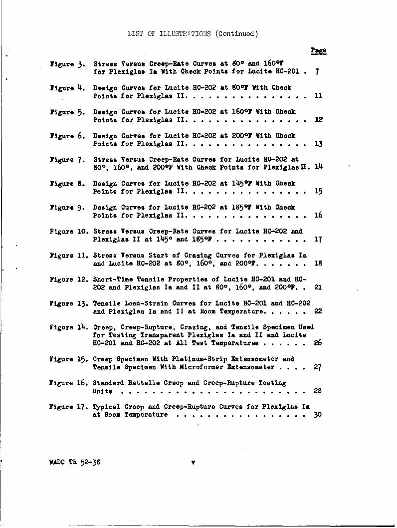
Figure 2. Design Curves for Plexiglas I& at 160O0 With CheckPoints for Lucite HC-201 . ..... . . . . .. . . . 6
WADC TR 52-38 iv
I IST OF ILLUSTR.ATIONS (Continued)
Page
Figure 3. Stress Versus Creep-Bate Curves at 800 and 160oFfor Plexiglas Ia With Check Points for Lucite NC-201 . 7
Figure 4. Design Curves for Lucite HG-202 at 8001 With CheckPoints for Plexiglas II....... ...... 11
Figure 5. Design Curves for Lucite HC-202 at 160o0 With CheckPoints for Plexiglas II . ... . ........... 12
Figure 6. Design Curves for Lucite HC-202 at 2000F With CheckPoints for Plexiglas II. . .o. . . . . , . . . . . . 13
Figure 7- Stress Versus Creep-Rate Curves for Lucite HO-202 at800, 1600, and 200oF With Check Points for PlexiglaslU. 14i
Figure 8. Design Curves for Lucite HO-202 at 1I45F With CheckPoints for Plexiglas II. . .. .. .. . .... . . 15
Figure 9. Design Curves for Lucite KC-202 at 1850F With CheckPoints for Plexiglas II. . . . * . .* e . . .... 16
Figure 10. Stress Versus Creep-Rate Curves for Lucite HC-202 andPlexiglas II at 1450 and 1851. . ........ .. 17
Figure 11. Stress Versus Start of Crazing Curves for Plexiglas Iaand Lucite HO-202 at 800, 1600, and 2000F . ...... 18
Figure 12. Short-Time Tensile Properties of Lucite HC-201 and HC-202 and Plexiglas Ia and II at 800, 1600, and 20001. . 21
Figure 13. Tensile Load-Strain Curves for Lucite HC-201 and RC-202and Plexiglas Ia and II at Boom Temperature. . . . . . 22
Figure l4. Creep, Creep-Rupture, Crazing, and Tensile Specimen Usedfor Testing Transparent Plexiglas Ia and II and LuciteHC-201 and HG-202 at All Test Temperatures . . . . . . 26
Figure 15. Creep Specimen With Platinum-Strip Extensometer andTensile Specimen With Microformer Extensometer . . . . 27
Figure 16. Standard Battelle Creep and Creep-Rupture TestingUnits . . . . . . . *.. . *. .. . . *.. . . . * *.. . . 29
Figure 17. Typical Creep and Creep-Rupture Curves for Plexiglas Iaat Boom Temperature . . ...... ......... 30
WADC TB 52-38 v

SUMMARY
Tensile creep and creep-rupture, crazing, short-time tensile, anddeterioration tests were made on two regular (Plexiglas Ia and LuciteHC-201) and two heat-resistant (Lucite HC-202 and Plexiglas II) grades ofacrylate sheet at room temperature, 1600 and ZO0F.
In general, the data obtained were within the normal scatter band formaterials of this type. The following tabulation summarizes the rupturedata for the materials tested:
Temperature, Stress, psi, to Produce Rupture inMaterial OF 10 Hours 100 Hours 1000 Hours
Plexiglas Ia 80 5,750 5,050 4,400Lucite HC-201 80 5,200 4, 550 3,900Lucite HC-202 80 7,400 7,000 6,300Plexiglas II 80 7,400 6,800 6, 100 Est.
Plexiglas Ia 160 1,750 1,300 1, 050Lucite HC-201 160 1,350 1,250 1,200Lucite HC-202 160 3,320 3, 0(50 2,770 Est.Plexiglas II 160 3,290 3,000 2,700
Lucite HC-202 200 2,050 1,700 1,300Plexiglas II 200 1,700 1,350 1,000
Note: Complete series of tests were made on Plexiglas Iaand Lucite HC-202. and check tests on Lucite HC-201and Plexiglas II.
At 200 0 F, the regular acrylate sheet did not have any practical load-carrying ability.
The heat-resistant material was much superior to the regular varietyin resistance to crazing at elevated temperatures. The following tabulationis a summary of the crazing data:
Temperature, Estimated Stress, psi, to Produce Crazing inMaterial OF 10 Hours 100 Hours 1000 Hours
Plexiglas Ia 80 2,850 2,500 2,100Lucite HC-202 80 3,450 2,800 2,500
Plexiglas Ia 160 700 450 200Lucite HC-202 160 2,250 1,750 1,300
Lucite HC-202 200 1,650 1,200 700
WADCTR 52-38 v1

The short-time tensile strength of the regular material ranged from
8240 psi at room temperature to 150 psi at 2000F. The heat-resistant ma-terial varied from 9980 psi at room temperature to 2660 psi at 200 0 F.
All of the materials were quite stable, as shown by the deteriorationtests. None of the materials lost more than 0. 69 per cent of its weightafter exposure at 2 0 0 OF for 1000 hours.
WADCTR 52-38 vii

INTRODUCTION
This report covers work done under Contract Number AF 33(038)-10818 and is concerned with four acrylic materials:
A. Two regular acrylates1. Plexiglas Ia2. Lucite HC-201
B. Two heat-resistant acrylates1. Lucite HC-2022. Plexiglas II
Tensile creep and creep-rupture, craming, short-time tensile, anddeterioration tests were conducted on each of the above materials. Temp-eratures of interest were between room temperature (800F) and 2000 F.
The short-time tensile tests were made in a Baldwin-SouthwarkUniversal Testing Machine. Deformations were measured, whereverpossible, with a microformer extensometer. The creep, creep-rupture,and craming tests were made in standard Battelle creep frames and furnaces.Test procedures are described briefly in Appendix I.
The platinum-strip type of extensometer was used to measure deformationin the creep and creep-rupture tests.
WADC TR 52-3S vill

SPECIFICATIONS OF MATERIALS TESTED
The four acrylate materials tested under this program were obtainedaccording to specifications given in the contract. The specifications andsheet identification were as follows:
Plexiglas Ia (regular)Supplier and manufacturer: Rohm and Haas CompanySpecification number: AN-P-44aSize panel: 3 x 4 feet x 1/4 inch thickMix number: W525-21
Lucite HC-201 (regular)Supplier and manufacturer: E. I. du Pont de Nemours
and Company, Inc.Specification number: AN-P-44aSize panel: 3 x 4 feet x 1/4 inch thickSheet number: 13733
Lucite HC-202 (heat resistant)Supplier and manufacturer: E. I. du Pont de Nemoursand Company, Inc.
Specification number: MIL-P-5425Size panel: 3 x 4 feet x 1/4 inch thickSheet number: 2533
Plexiglas II (heat resistant)Supplier and manufacturer: Rohm and Haas CompanySpecification number: MIL-P-5425Size panel: 3 x 4 feet x 1/4 inch thickMix number: WLK569-33
This evaluation program was carried out to determine the level ofproperties of the regular and the heat-resistant grades of acrylate sheet,and the differences between them. It is emphasized that the data includedin this report were obtained on specimens from only one lot of each of thematerials. Tests of other lots of the materials would probably give slightlydifferent values. Therefore, minor variations in the properties of materialin the same grade are not necessarily significant and should not be used torate the materials according to strength characteristics.
WADC TR 52-38 1

PREPARATION AND HEAT TREATMENT OF TEST SPECIMENS
The test materials were handled with extreme care during the machin-ing operations. The protective paper covering had to be removed from thespecimen material before machining because the cutting tool tended to re-move it and it was difficult to keep the specimens from slipping under thepaper. No lubricant was used during the machining operation and care wastaken that the specimens did not overheat. No undercutting was noticed atthe fillets.
The machined specimens were annealed (stress relieved) prior totesting. The regular acrylates (Plexiglas Ia and Lucite HC-Z01) wereheated for 30 minutes at 125 0 C (257rF). The heat-resistant acrylates(Lucite HC-202 and Plexiglas II) were heated for 30 minutes at 145 0 C (293 0 F).The specimens were suspended from one end during the annealing operation.All materials were allowed to cool to room temperature in about 1-1/2 to 2hour s.
TENSILE CREEP AND CREEP-RUPTURE, ANDCRAZING TESTS
Tensile creep and creep-rupture tests were made on two regular andtwo heat-resistant grades of acrylate sheet. The regular acrylates weretested at 80*and 160*F and the heat-resistant materials at 80P, 16(P, and Z000F.A few tests were also conducted at 1450 and 185 0 F. These latter tests weremade unintentionally because of a failure in the temperature control equip-ment. The results of these tests are reported herein but very little com-ment will be made regarding them.
The creep-rupture tests covered rupture times from about one to1000 hours. Some lower stress creep tests were made to obtain creep-ratedata and also the low deformation points for the design curves. A descrip-tion of the test procedure is given in Appendix I.
It was agreed with representatives of the Materials Laboratory thatonly one of the regular and one of the heat-resistant materials would becompletely tested in creep and creep rupture. It was assumed that thematerials would be closely comparable, and check tests would be made todetermine this similarity. Subsequent check tests proved the assumption tobe correct as shown by the test data obtained. Therefore, a complete seriesof tests was made on Plexiglas Ia and Lucite HC-202 and check tests weremade on Lucite HC-ZO1 and Plexiglas II. It was also agreed that no testswould be made at stresses below 500 psi.
Start of crazing was readily noticeable in the room-temperature creepand creep-rupture tests; these data are shown in the figures containing thedesign curves. At temperatures above room temperature, however, it wasnot possible to observe whether crazing had started while the test was inprogress because the specimen was enclosed in the furnace. In this case,
WADC TR 52-38 2

the specimens were observed after the tests were discontinued and it wasnoted whether or not crazing had taken place. These tests were generallyof about 1000 hours' duration. Thus the stress for start of crazing at1000 hours could be estimated from these tests.
In order to obtain another point on the crazing curves, several testslasting 75 hours were made on each material at various stresses. After75 hours, the specimens were removed from the furnace and inspected forcrazing. From these tests, the stress to start crazing at 75 hours couldbe estimated. The crazing curves were then plotted from these two esti-mated points as shown in the design curves and in Figure 11 comparing thecrazing properties of the materials tested.
The creep laboratory, in which the creep, creep-rupture, and crazintgtests were made, was temperature controlled at 80 0F. Relative humiditywas not controlled and varied between 38 and 59 per cent.
Regular Acrylates
All creep, creep-rupture, and crazing data obtained on the regularacrylates, Plexiglas Ia and Lucite HC-201, are given in Table 1. Thesedata are shown as design curves in Figures 1 and 2 and as stress versuscreep-rate curves in Figure 3.
A complete series of tests was made on Plexiglas Ia at 80Oand 160PF,but only a few check tests were conducted on Lucite HC-201 at the sametemperatures. No tests were made on these materials at 200ZF because oftheir extremely low strength. A trial test on Plexiglas Ia at 200*F resultedin about 75 per cent elongation immediately upon application of a 350 psistress.
As shown in Figure 1, Plexiglas Ia has about 500 psi higher creep-rupture strength at 80'F than does Lucite HC-201. The creep rates forthese two materials at 80OF appear to be about the same (Figure 3).
At 160*F, Plexiglas Ia shows the higher creep-rupture strength, butonly at the higher stresses. A test at 1200 psi shows Lucite HC-201 tohave the higher strength (Figure 2). The stress versus creep-rate curvesof Figure 3 show that Plexiglas Ia at 160 0F also has the higher creepstrength at the higher stresses. At the lower stresses, Lucite HC-201 ap-pears to be the stronger of the two materials.
The room-temperature creep and creep-rupture tests were observedfrom time to time to determine start of crazing. This was done only onPlexiglas Ia, the material on which the complete series of tests was made.It appears from the design curves of Figure 1, that crazing in Plexiglas Ia
WADC TR 52-38 3

V)
s~ a
C, M
.j ~ ~ 0s -n - WL W -0.-wL om
2 l 8 IW - I S? I I II I I F
IL -UCR R~U C4R R 4
g 0.= - -I I C
D.-4 -" -e)
orJ*gpe i I I i I - to I W Ir co ci- L" I I I
0 -
4R 4 f CD -W C) C14 C- C- L" C= CDC) ~ - 1 C 4
zoo C -
-c=, C r- 00 Le? U C)gJ- ii I I I = I C4 cI C= I= C= c= **** C
W 3O - (
piW3 4 CD C "1 C) C= U1 o C 1CDU3 3 O0
2j -*4 C= C: - 1C) C) C =C; C) V)
U.!~iAcadt~ o C coV coP.C CL)
S~ co CD~ 2 4--
CL U)
Uix ms aR2 .2 )zi s444444------ -4 14 14 C
-4 r-C) C 3C l 2 C) u
CU-4 CD C2ar- 1
WAD TR 52-38

I--____ 0 8____ ____ ____ - 0
.pI I tCo
I-
x -
0 X _'0m
-L 0 iILI~
I f I
R -cX Nt
0 co 0
0 C
IL I 2
IdIC I',,s%.S
LIL
WADC TR 52-38
00
00
w
00
(D0
(nl
0.
eJ0 0
c -
rs 0-00 0SB4SWADO in 523

00
C',
W
L) I.-
Un 08x- a
0. >
t- R
trw
LL&L AlLL
C5~
Isd ',501 ss4S (
WADC TE 52-358

at room temperature begins between 0. 7 and 1. 0 per cent deformation
under the conditions of these tests.
At 160F, the estimated crazing curve for Plexiglas Ia falls between
the one and the two per cent deformation curves (Figure 2).
Results of the tests conducted on the regular acrylates at 1450F areshown in Table 1 and Figures 2 and 3.
Heat-Resistant Acrylates
The two heat-resistant grades of acrylate, Lucite HC-202 andPlexiglas II, were tested at room temperature, 160P, and 200*F. A com-plete series of creep and creep-rupture tests was made on Lucite HC-202and only a few check tests on Plexiglas II. Some special crazing tests werealso conducted on Lucite HC-202 at 160Pand 20CPF.
Results of the creep, creep-rupture, and crazing tests are given inTable 2. The results were plotted as design curves in Figures 4, 5, and 6,and as stress versus creep-rate curves in Figure 7.
Results of the creep and creep-rupture tests on Lucite HC-202 andPlexiglas II at 145 and 185 F are given in Table 2 and Figures 8, 9, and 10.
An inspection of Figures 4 through 7 will show that the creep andcreep-rupture strengths of Lucite HC-202 and Plexiglas II at room tempera-ture, 1600 and 200°F are very nearly the same. Lucite HC-202 may showa slightly greater strength, especially at 2000 F.
Crazing was observed to start between one and two per cent de-formation in Lucite HC-202 at room temperature (Figure 4). At 160PF(Figure 5), it appears that this material starts to craze between about 1 and3 per cent deformation. At 200 0F, the amount of deformation at whichcrazing starts may be more dependent upon the strain rate. The crazingtests at 75 hours' duration indicated that, between 1200 and 1300 psi,crazing did not start until 10 per cent deformation had been exceeded.However, at 1000 psi, crazing had started in less than 1200 hours before3 per cent deformation had been reached. (See Figure 6 and Table 2,Specimen HC-202-3.)
Figure 11 is a plot of the stress versus start-of-crazing time forPlexiglas la and Lucite HC-202 at 800, 1601, and 200°F. After 100 hours at80'F, the regular variety had about 90 per cent as much resistance tocrazing as the heat-resistant variety. However, at 1601F, the superiorityof the heat-resistant variety is very significant. The regular variety having
WADO ?R 52-38 8

as 00 4= DO ba CD
08 1 8o=
N (B- 7
LL a
Z 6i.jm Rni
P- -2 - - m 1
-0 g I I ~ I ICII 1 I * II
F4 Cý en n CDm
mg C" U
C4 9I CJ I ( I II =,
0 L
Uj L ~J%
LU* ~~ . na
ul cl 5c c,
CI cc Uý Un la cm
-c, CDC C i =
T- T -0 T
8.- - CD co - -=- - --
.0 4-4 C4N
c~jC-t v4C.4cli c4
*I C-J4
.ICý4 C4C4C4 $ A C 14
Z~. 6~= 6~ 666CL C == == CL C=L~
WaDC TR 52-38 9

5 Z3
5- cc -or -41
Uý m) L"a , :)2
CD C-4 r
Ioe I IR IR U"c
j~ 4 Vg.0"rc
11 1 1111 IcI I4 I4 U- C4 Lei' I IIIC
oo en L" U1 D 41I IR C ý !C; liii I- CA ;I I C:, ý (Z CDJ C-.
- '- "
LU IF
-10
IZ =a AM q I ') a
-t '.R U, uR -1 '.,-i -
O~4 1 1 1 ~ cc3c -JJd 4.L iCD~cJ ID CD 4=I 6 4
CC
E- 4- L,"U - UC".)C 19J"U4P A Im04~ ~ ~ ~ ~ C~ Ct ~jC t - -jC4CjCJCjCJCjC ýCJC4Cý da~ ~ ~ ~ R a ZC1
C- a- -
AUF. 88~8 _8
I- -4- -4C14
d) ~ ~ ~ .toa a coC !
X0- Z f (50C
.1D LfT.C% 523 JCJ10CJCJ

0 CM
04 0 0
4 0
06 0
.E--
LL~
00
0'J
WZ
0 3d ~~OOOI'e
WADa TB 023~

Uf)
00w
____0 0U.Cf)
z0~
Pý w
.0- U-c__ __ ____b.0
UE
0~c4-
_ALM 020
00
Oc
4 -
>0o
0wz.
!sd 0001 'I@ojJS0
WADC TR 52-38 12

V:c,,
_ _ _ _ _ _ _ -0
0
C -C
0 -0
00 p MID
-~ 0
0 a
_ _ _ _ 0
-00
h. Z
0 00 00r
!S___O ____S Co
WL._____ __ _ 52-3_ 13

0
-- X- -- z
X1z
E
x 0
0-0
WI3 1.. u
0
0' -0
CL I
__ 0~
w
wORI Is C
6~ U -0 0 0 060d 001ts8
WADO TB 52-38i1

-0J
0
-i CL
-0~
CL)
00
wm
LLo00
o3 IA
o00
____ 0......-i
0 0
06 U):3a
03
I.-C(n0
> ..fo-
Wz0.~
c6i
00
!sd 0001 'ssjSOJ
WADC TE 52-78 1

0
-00
a-__ C,,
C-i -
00
0.,
w
o-
0
-00
Os 00
02
-o-J
0
LLJ
_____0 _ _ _ _ E_
cli w -
0 >i
2 (D!SdOOOI~F 0sa4 L
WADC~~~ TB5-51

9 0
CD
a.-
4
4
9 ~IN0~
CLz4
CYC-)
I-r
x 0 -
I- W
0 0~___ w c0 0 0 0 0 o 40 %-fw
Cd 4 If ~i - CJd 0CDU-d 001 )so
WADC R 5219I 1

00zC
_e 0 La
zo
LLE0= Do
_ _ _ _ _ _ _ FA
IAo
0~C' 00 0ND -
W.ADC- 1052381

only about 25 per cent as much resistance to crazing as the heat-resistantvariety at 100 hours.
When the temperature was increased from 160Dto 200 0F, the stressfor incipient crazing in 100 hours decreased from 1750 psi to 1200 psi forthe heat-resistant acrylate sheet. This is a decrease of about 31 per cent.When the crazing data for the heat-resistant acrylate sheet are examined,it is found that there is a linear relation between temperature and stressfor incipient crazing. In the testing temperature range 80"to 200 0F, thestress to produce crazing in 10, 100, or 1000 hours decreased approxi-mately 15 psi for each degree increase in temperature.
SHORT-TIME TENSILE TESTS
Short-time tensile tests were made on all four of the materials atroom temperature, 1600 and 200 0F. Only at room temperature, however,was it possible to obtain yield strength, proportional limit, and elasticmodulus values. A microformer type of extensometer was attached to theroom-temperature tensile test specimens in order to obtain these values(Appendix I). At 160 0 and 200 0 F, all four materials soften too rapidly toallow an extensometer to be attached to the specimens. Results of theseshort-time tensile tests are shown in Table 3 and Figure 12. Figure 13shows the load- strain curves from which the yield strength (0. 1 and 0. 2 percent offset), proportional limit, and elastic modulus data were obtained.
The tensile properties of the heat-resistant acrylate sheet weresuperior to those for the regular grade, even at room temperature. At200 Fl the superiority of the heat-resistant grade was very significant.
The short-time tensile strength of the regular material ranged from8240 psi at room temperature to 150 psi at 200 0F. The heat-resistant ma-terial varied from 9980 psi at room temperature to 2660 psi at 2000 F.
DETERIORATION TESTS
A series of deterioration tests (time at temperature versus weightloss) was made in duplicate on the four acrylic materials at 16 0°and 200"F.This was done in order to find what effect exposure for 24, 200, and 1000hours at these two temperatures would have on the stability of Plexiglas Iaand II and Lucite HC-201 and HC-Z02. The results, in per cent weight lossfor each exposure, are shown in Table 4. The samples used for the testswere one inch square by 1/4 inch in thickness.
WADC TR 52-38 19

TABLE 3. SHORT-TIME TENSILE DATA FOR LUCITE HC-201 AND HC -202 AND
PLEXIGLAS Ia AND II AT 80? 160, AND 200"F
Rate of Pull - 0. 06 Inch Per Minute
Average Yield
Tensile Tensile Strength, psi Elastic ProportionalSpecimen Temp. Area, Strength, Strength, 0. 10 0.2% Modulus, Limit,
Material Number F sq in. psi psi Offset Offset psi psi
Plexiglas Ia PIa-1 Room Temp 0.1260 8260 - 4250 5040 318,000 1980
PIa-2 Room Temp 0.1250 8220 8240 4240 5040 352,000 1760
PIa-3 160 0. 1254 2550 - - - - -
PIa-4 160 0.1269 2480 2510 - -
PIa-5 200 0. 1273 150 150 - - - -
Lucite HC-201-1 Room Temp 0.1165 7120 - 4070 4970 352,000 1840
HC-201 HC-201-2 Room Temp 0. 1153 6970 7040 4290 5060 347,000 1730
HC-201-3 160 0. 1172 2560 - - - - -
HC-201-5 160 0. 1210 2070 2260 -
HC-201-6 200 0. 1184 170 170 - - - -
Plexiglas II PII-1 Room Temp 0.1183 9850 - 4440 5530 397,000 1730
PII-2 Room Temp 0. 1208 9960 9900 4350 5390 385,000 1450
PII-3 160 0.1204 5150 - - - - -
PII-4 160 0. 1165 5020 5080
PII-5 200 0.1242 2410 -
PII-6 200 0. 1232 1870
PII-7 200 0. 1175 3210
PII-8 200 0. 1212 2920 - -
PII-26 200 0. 1288 2640 - -
PII-27 200 0. 1323 2640 -
PII-28 200 0. 1293 2940 -
P11-29 200 0. 1348 2670 2660
Lucite HC-202-1 Room Temp 0.1303 9890 - 4710 5640 399,000 2070HC-202 HC-202-2 Room Temp 0.1265 10080 9980 5020 6050 379,000 2450
HC-202-3 160 0. 1262 5780 - - - - -
HC-202-4 160 0. 1267 5520 5650 - -
HC-202-5 200 0. 1262 4000 -- -
HC-202-6 200 0. 1260 4600 -- -
HC-202-7 200 0. 1257 2410 -- -
HC-202-13 200 0. 1185 4680 -- -
HC-202-X 200 0. 1197 4340 -
HC-202-26 200 0.1294 3820 - -
HC-202-27 200 0. 1254 3310 - -
HC-202-28 200 0. 1258 3740 - -
HC-202-29 200 0. 1240 3270 3800
WADC TR 52-38 20
- " = a a i Fw

12.0
0-Lucite HC-202x-Plexiglas 3r
10.0 p-Lucite HC-201I o~c -A-Plexiglas Ia
S.e
Z0.0
000
06.0 -3Yield strength
(n (0.2 % offset)
4.0Elastic modulus410
x
2.0 Prprtionallimit
0
OL.-4-
Temperature ,0F7
FIGURE 12. SHORT-TIME TENSILE PROPERTIES OF LUCITE HC-201,HC-202, AND PLEXIGLAS Ia AND nL AT 8(f, 16609 AND 200OF
WADO Ti 52-38 21

0
'oo
-li (D 0
000
0 C~0
___________I I_______ II
cn ( (. 0 PC~j ) C)- r0
C~j C-Jo.E
spunodx pol
WADO B 5238 2

TABLE 4. DETERIORATION DATA ON PLEXIGLAS Ia AND II
AND LUCITE HC-201 AND HC-202 AT 160AND2009F
Specimen Temp. Per Cent Weight Loss, After Exposure ofNumber(a) OF 24- Hours 200 Hours 1000 Hours
PIa-A 160 0.20 0.48 0.53PIa-B 160 0.24 0.48 0.52HC-201-A 160 0.18 0.34 0.36HC-201-B 160 0.17 0.32 0.36
PIa-C 200 0.47 0.58 0.69PIa-D 200 0.49 0.55 0.65HC-201-C 200 0.33 0.38 0.44HC-201-D 200 0.30 0.35 0.38
PII-A 160 0.18 0.37 0.40PII-B 160 0.16 0.35 0.40HC-202-A 160 0.14 0.35 0.43HC-202-B 160 0.17 0.34 0.42
PII-C 200 0.23 0.38 0.41PII-D 200 0.24 0.42 0.42HC-202-C 200 0.24 0.43 0.46HC-202-D 200 0.23 0.43 0.45
(a) Specimen identityPIa - Plexiglas Ia
PHI - Plexiglas IIHC-201 - Lucite HC-201HC-202 - Lucite HC-202
WADC TR 52-38 23

The two heat-resistant acrylates, Plexiglas II and Lucite HC-202,
had very similar weight losses after each treatment. Of the two regularacrylates, Lucite HC-201 had the lower weight loss.
A comparison among all four materials indicates that there is proba-bly no significant difference between them, although Plexiglas Ia showedslightly greater weight loss than the others. It is possible that most of the
loss in weight of the specimens was caused by the elimination of moisture.
WADC TB 52-35 24

APPENDIX I
Test Procedures
Short-Time Tensile Tests
The short-time tensile tests were made in a Baldwin SouthwarkHydraulic Testing Machine. The elevated-temperature tests were madein an electric resistance-heated furnace 7 inches in diameter and 12-1/2inches long. The furnace was fitted with a copper liner to help maintain auniform temperature in the gage section of the specimens.
Two chromel-alumel thermocouples were used on each test to meas-ure and control the temperature. The specimens were heated to the testtemperature in about 1/2 hour and then held at this temperature for ap-proximately 1/2 hour prior to loading. A Foxboro controller maintained thedesired temperature to an accuracy of about + 5°F.
The tensile specimens were 24 inches long with a 2-1/4-inch-long by1/2-inch-wide gage section. All four materials tested were 1/4 inch thick.The machining specifications for these specimens are shown in Figure 14.
Microformer-type extensometers with a sensitivity of 5 microincheswere used to measure strain at room temperature. The method of attach-ment is shown in Figure 15. Strain at elevated temperatures could not bemeasured because the extensometer clamps cut too deeply into the softenedmaterials. The specimens were pulled at a head speed of 0. 06 inch perminute which is equal to about 0. 0026 inch per inch per minute in the gagelength of the specimens.
Tensile Creep and Creep-Rupture Tests
The tensile creep and creep-rupture tests were made in standardBattelle creep-testing units and furnaces. Figure 16 shows a group of foursuch units. Although these units are shown in the process of testing metalspecimens, a similar arrangement was used for testing the acrylates.
Each testing unit is equipped with a chromium-plated copper or steelshell furnace 6 inches in diameter and 18 inches long, wound with 14-gageChromel A wire and insulated with Sil-O-Cel. A small window is providedat both front and back of the furnace for measuring the deformation of thespecimen by optical means. These furnaces also had a copper lining toimprove the temperature uniformity along the gage section of the specimens.
The test temperature of each furnace was maintained by a TagCelectroy Indicating Controller equipped with a throttling mechanism for
WADC TR 52-38 25

0 00 C
0 = u I--N o 0 0 0)
0-M-=00-.O04-00 .Jg0.W~0000 .
0. 0, 00
00
w0 wOO D~ C
4- 4) D-*
0- Z4Zj-00
CŽ r- .E -
U) 0 w E z
CZ
N0U,
0w
I--
I z
a) WzI-
01- L- r-i-00 0 < U)00 0 -U
E * E wZ<-
I -- 00uI-
0 C0
4- cr
S :3
WAIDC TR 52-38 26

FIGURE 15. CREEP SPECIMEN WITH PLATINUM-STRIP EXTENSOM!ETEAND TENSILE SPECIMEN WITH MICROPORMER EXTENSOMETER
Note: Front view of the creep specimen and edgeview of the tensile specimen are Ehown
WADO TR 52-18 27

FIGURE 16. STUANDAI BEM'TTLLI CREEP An CREiEP-RUPTURE TESTING UNITS
WADC TR 52-35 25
closer control, or by a Foxboro controller to which an anticipating device
had been added to improve the temperature control. The temperature of the
creep and creep-rupture tests was held to an accuracy of about *2 F.
The stress was applied to the test specimen either by means of a 9 to
1 lever arm ratio or by direct loading with a dead weight after the specimen
had reached the test temperature.
The tensile creep and creep-rupture specimen was 22 inches long and
had the same gage-length dimensions as the short-time tensile specimen as
shown in Figure 14.
The deformation of the test specimens was measured by means of a
platinum-strip extensometer attached to the gage length of the specimens.
The extensometer and the method of attachment are shown in Figure 15.
The platinum extensometers consist of two strips, one of which slides with-
in the folded-over edges of the other. The surfaces of the strips are pol-
ished and a series of very fine cross marks scribed on them. Two cross
marks, one on each strip, are chosen as reference marks and the distance
between them is measured periodically with a filar microscope. The change
in length or creep of the test specimen is determined by measuring the
change in the distance between the reference marks.
The microscope with which the deformation readings were made has
an eyepiece fitted with a filar micrometer and is mounted on a graduated
screw. The smallest division on the eyepiece is 0. 00005 inch, which, on
a 2-inch gage length, would be equal to 0. 0025 per cent.
Deformation readings are usually made daily by two observers.
Extensometers are generally attached to both the front and back of the test
specimen to obtain greater accuracy and to check on axial loading.
The optical readings are converted to percentages and plotted as time-
deformation curves as shown in Figure 17. The deformation readings in
both the front and back of the specimen of both observers are averaged to
produce these curves.
In all the creep and creep-rupture tests, the no-load, at-temperature
condition of the test is represented by the zero or starting point of the time-
deformation curves. These curves show all deformations except thermal
expansion that occur during the heating of the specimen.
When the load is applied, the specimen deforms an initial amount,
which is generally all elastic deformation unless the proportional limit has
been exceeded. This is shown by point "a" in each of the curves of Figure
17. (The subscripts indicate the number of the test specimen in each case.)
Actual creep of the specimen starts at this point. The part of the time-
deformation curves from a to b is called primary creep and is characterized
WADC TR 52-38 29

oD 0
~ *0(0
to;c 0 1--
0 -oo 0__ _ _ ~ .
0o E 0 :
-22 0-. 0
13 . 0 '0
0.0
o0 LLO
00>
-2 0 W CI-
00 fc
0. 0 0U 0
00rli
In
0
W C
'o z
CNJ w00
CL~~ 0 l0
0- 0C-4 2_
00
0MLW --
WADC TR 52-39 30

by a decreasing creep rate. Secondary creep begins at point b and ends atpoint c. This part of the time-deformation curve is characterized by(1) an approximately uniform creep rate and (2) the lowest creep rate of theentire test. It is generally the most important part of the creep curve andis identified as a certain minimum creep rate in per cent per hour. Pointc on the curves indicates the start of third-stage creep and it is character-ized by an increasing creep rate until failure occurs at point d. Point c isalso identified as the transition point.
Specimen PIa-17 was tested in creep and it was discontinued whilestill in the second stage. This test, therefore, does not show the transitionor rupture points. When discontinued, the load was removed from the speci-men resulting in the recovery of the elastic portion of the initial deformationas shown in Figure 17.
The deformation above point "a" in each curve is defined as the totalcreep strain. The total deformation, on the other hand, is the deformationabove the abscissa or base line. In other words, initial strain plus creepstrain is equal to total deformation.
In order to present these creep data in a more concise and usefulform, design curves were prepared from the time-deformation curves.The times to produce total deformations ranging from 0. 5 to 10 per centwere taken from the variously stressed tests and assembled in table formas shown in Tables 1 and 2 of the text. Also taken from the time-deformationcurves and included in these tables were rupture times or, if discontinued,maximum time of test, minimum creep rates, start of crazing, initial de-formation, and time and amount of deformation at the start of third- stagecreep. It is not generally possible to obtain all of these data from a singletest but a family of as many as ten tests was required to produce a set ofdesign curves on each material at any one temperature. These data werethen plotted as design curves (stress versus log of time) and stress versuscreep-rate curves as shown in the text. It is emphasized that all deforma-tions are total deformations and include all strain except thermal expansion.
WADOC TR 52-38 31