Embed Size (px)
Citation preview
I
R
1
2
3
4
5
6
7
8
9
10
11
12
13
T
14
15
A
PHONE: 516.328.3300 • FAX: 516.326.8827 • WWW.SDP-SI.COM
ELEMENTS OF METRIC GEAR TECHNOLOGY
T-17
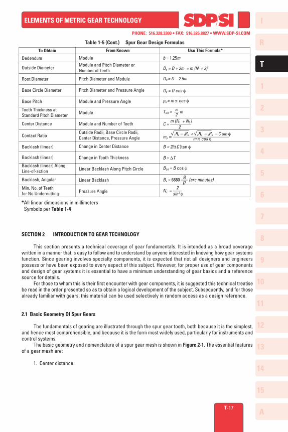
Table 1-5 (Cont.) Spur Gear Design Formulas
*All linear dimensions in millimeters Symbols per Table 1-4
SECTION 2 INTRODUCTION TO GEAR TECHNOLOGY
This section presents a technical coverage of gear fundamentals. It is intended as a broad coverage written in a manner that is easy to follow and to understand by anyone interested in knowing how gear systems function. Since gearing involves specialty components, it is expected that not all designers and engineers possess or have been exposed to every aspect of this subject. However, for proper use of gear components and design of gear systems it is essential to have a minimum understanding of gear basics and a reference source for details. For those to whom this is their first encounter with gear components, it is suggested this technical treatise be read in the order presented so as to obtain a logical development of the subject. Subsequently, and for those already familiar with gears, this material can be used selectively in random access as a design reference.
2.1 Basic Geometry Of Spur Gears
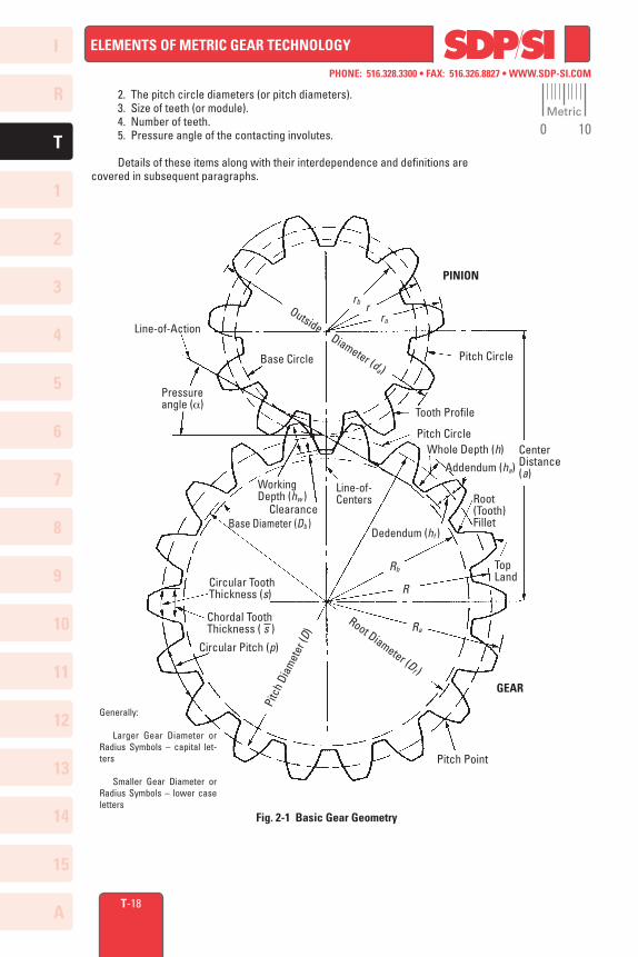
The fundamentals of gearing are illustrated through the spur gear tooth, both because it is the simplest, and hence most comprehensible, and because it is the form most widely used, particularly for instruments and control systems. The basic geometry and nomenclature of a spur gear mesh is shown in Figure 2-1. The essential features of a gear mesh are:
1. Center distance.
To Obtain
Dedendum
Outside Diameter
Root Diameter
Base Circle Diameter
Base Pitch
Tooth Thickness at Standard Pitch Diameter
Center Distance
Contact Ratio
Backlash (linear)
Backlash (linear)
Backlash (linear) Along Line-of-action
Backlash, Angular
Min. No. of Teeth for No Undercutting
Use This Formula*
b = 1.25m
Do = D + 2m = m (N + 2)
DR = D – 2.5m
Db = D cos f
pb = m p cos f
pTstd = –– m 2 m (N1 + N2 )C = ––––––––– 2 √1Ro – 1Rb + √2Ro – 2Rb – C sin fmp = –––––––––––––––––––––––– m p cos f
B = 2(DC )tan f
B = DT
BLA = B cos f
BBa = 6880 ––– (arc minutes) D 2Nc = –––– sin 2 f
From Known
ModuleModule and Pitch Diameter or Number of Teeth
Pitch Diameter and Module
Pitch Diameter and Pressure Angle
Module and Pressure Angle
Module
Module and Number of Teeth
Outside Radii, Base Circle Radii, Center Distance, Pressure Angle
Change in Center Distance
Change in Tooth Thickness
Linear Backlash Along Pitch Circle
Linear Backlash
Pressure Angle
I
R
1
2
3
4
5
6
7
8
9
10
11
12
13
T
14
15
A
PHONE: 516.328.3300 • FAX: 516.326.8827 • WWW.SDP-SI.COM
ELEMENTS OF METRIC GEAR TECHNOLOGY
T-18
Generally:
Larger Gear Diameter or Radius Symbols – capital let-ters
Smaller Gear Diameter or Radius Symbols – lower case letters
PINION
GEAR
Outside Diameter (da)
rb rra
Pitch Circle
Tooth Profile
Pitch CircleWhole Depth (h)
Addendum (ha)Center Distance (a)
Root(Tooth)Fillet
TopLand
Pitch Point
Rb
R
RaRoot Diameter (D
f )
Pitc
h Di
amet
er (D
)
Circular Pitch (p)
Chordal Tooth Thickness ( s )
Circular Tooth Thickness (s)
Base Diameter (Db )Clearance
Working Depth (hw )
Line-of-Centers
Dedendum (hf )
Pressure angle (a)
Line-of-Action
Base Circle
Fig. 2-1 Basic Gear Geometry
2. The pitch circle diameters (or pitch diameters). 3. Size of teeth (or module). 4. Number of teeth. 5. Pressure angle of the contacting involutes.
Details of these items along with their interdependence and definitions are covered in subsequent paragraphs.
Metric
0 10
I
R
1
2
3
4
5
6
7
8
9
10
11
12
13
T
14
15
A
PHONE: 516.328.3300 • FAX: 516.326.8827 • WWW.SDP-SI.COM
ELEMENTS OF METRIC GEAR TECHNOLOGY
T-19
2.2 The Law Of Gearing
A primary requirement of gears is the constancy of angular velocities or proportionality of position transmission. Precision instruments require positioning fidelity. High-speed and/or high-power gear trains also require transmission at constant angular velocities in order to avoid severe dynamic problems. Constant velocity (i.e., constant ratio) motion transmission is defined as "conjugate action" of the gear tooth profiles. A geometric relationship can be derived (2, 12)* for the form of the tooth profiles to provide conjugate action, which is summarized as the Law of Gearing as follows: "A common normal to the tooth profiles at their point of contact must, in all positions of the contacting teeth, pass through a fixed point on the line-of-centers called the pitch point." Any two curves or profiles engaging each other and satisfying the law of gearing are conjugate curves.
2.3 The Involute Curve
There is almost an infinite number of curves that can be developed to satisfy the law of gearing, and many different curve forms have been tried in the past. Modern gearing (except for clock gears) is based on involute teeth. This is due to three major advantages of the involute curve:
1. Conjugate action is independent of changes in center distance.2. The form of the basic rack tooth is straight-sided, and therefore is
relatively simple and can be accurately made; as a generating tool it imparts high accuracy to the cut gear tooth.
3. One cutter can generate all gear teeth numbers of the same pitch.
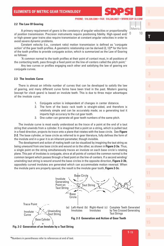
The involute curve is most easily understood as the trace of a point at the end of a taut string that unwinds from a cylinder. It is imagined that a point on a string, which is pulled taut in a fixed direction, projects its trace onto a plane that rotates with the base circle. See Figure 2-2. The base cylinder, or base circle as referred to in gear literature, fully defines the form of the involute and in a gear it is an inherent parameter, though invisible. The development and action of mating teeth can be visualized by imagining the taut string as being unwound from one base circle and wound on to the other, as shown in Figure 2-3a. Thus, a single point on the string simultaneously traces an involute on each base circle's rotating plane. This pair of involutes is conjugate, since at all points of contact the common normal is the common tangent which passes through a fixed point on the line-of-centers. If a second winding/unwinding taut string is wound around the base circles in the opposite direction, Figure 2-3b, oppositely curved involutes are generated which can accommodate motion reversal. When the involute pairs are properly spaced, the result is the involute gear tooth, Figure 2-3c.
Fig. 2-2 Generation of an Involute by a Taut String
Trace Point
Involute Curve
Base Cylinder
Unwinding Taut String
Involute Generating Point on Taut String
Base Circle
Base Circle
Taut String
(a) Left-Hand Involutes
(b) Right-Hand Involutes
(c) Complete Teeth Generated by Two Crossed Generating Taut Strings
*Numbers in parentheses refer to references at end of text.
Fig. 2-3 Generation and Action of Gear Teeth
Metric
0 10
I
R
1
2
3
4
5
6
7
8
9
10
11
12
13
T
14
15
A
PHONE: 516.328.3300 • FAX: 516.326.8827 • WWW.SDP-SI.COM
ELEMENTS OF METRIC GEAR TECHNOLOGY
T-20
2.4 Pitch Circles
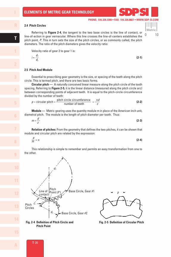
Referring to Figure 2-4, the tangent to the two base circles is the line of contact, or line-of-action in gear vernacular. Where this line crosses the line-of-centers establishes the pitch point, P. This in turn sets the size of the pitch circles, or as commonly called, the pitch diameters. The ratio of the pitch diameters gives the velocity ratio:
Velocity ratio of gear 2 to gear 1 is: d1 i = –– (2-1) d2
2.5 Pitch And Module
Essential to prescribing gear geometry is the size, or spacing of the teeth along the pitch circle. This is termed pitch, and there are two basic forms. Circular pitch — A naturally conceived linear measure along the pitch circle of the tooth spacing. Referring to Figure 2-5, it is the linear distance (measured along the pitch circle arc) between corresponding points of adjacent teeth. It is equal to the pitch-circle circumference divided by the number of teeth: pitch circle circumference pd p = circular pitch = –––––––––––––––––––––– = ––– (2-2) number of teeth z
Module –– Metric gearing uses the quantity module m in place of the American inch unit, diametral pitch. The module is the length of pitch diameter per tooth. Thus: d m = –– (2-3) z
Relation of pitches: From the geometry that defines the two pitches, it can be shown that module and circular pitch are related by the expression: p –– = p (2-4) m
This relationship is simple to remember and permits an easy transformation from one to the other.
Fig. 2-4 Definition of Pitch Circle and Pitch Point
d1
d2
PitchPoint (P ) Base Circle, Gear #1
Base Circle, Gear #2
Pitch Circles
Line of contact
p
Fig. 2-5 Definition of Circular Pitch
Metric
0 10
I
R
1
2
3
4
5
6
7
8
9
10
11
12
13
T
14
15
A
PHONE: 516.328.3300 • FAX: 516.326.8827 • WWW.SDP-SI.COM
ELEMENTS OF METRIC GEAR TECHNOLOGY
T-21
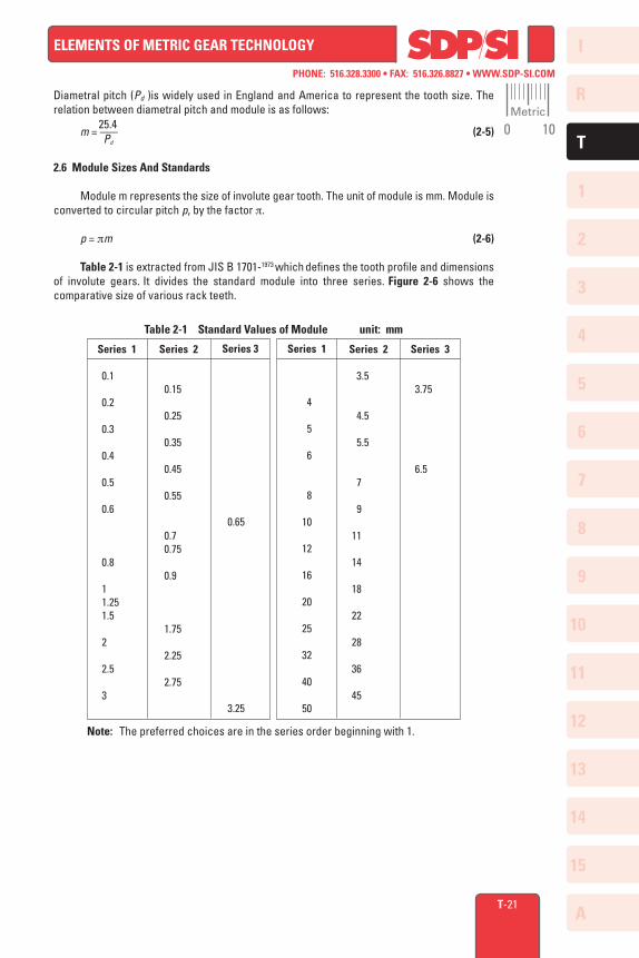
Diametral pitch (Pd )is widely used in England and America to represent the tooth size. The relation between diametral pitch and module is as follows: 25.4 m = ––– (2-5) Pd
2.6 Module Sizes And Standards
Module m represents the size of involute gear tooth. The unit of module is mm. Module is converted to circular pitch p, by the factor p.
p = pm (2-6)
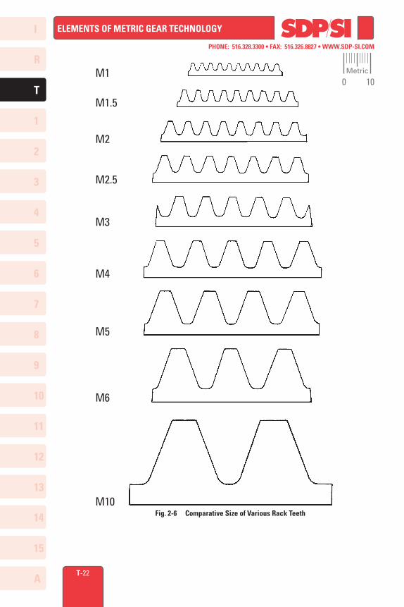
Table 2-1 is extracted from JIS B 1701-1973 which defines the tooth profile and dimensions of involute gears. It divides the standard module into three series. Figure 2-6 shows the comparative size of various rack teeth.
Series 1
0.1
0.2
0.3
0.4
0.5
0.6
0.8
1 1.25 1.5
2
2.5
3
Table 2-1 Standard Values of Module unit: mm
Series 3
0.65
3.25
Series 2
0.15
0.25
0.35
0.45
0.55
0.7 0.75
0.9
1.75
2.25
2.75
Series 1
4
5
6
8
10
12
16
20
25
32
40
50
Series 3
3.75
6.5
Series 2
3.5
4.5
5.5
7
9
11
14
18
22
28
36
45
Note: The preferred choices are in the series order beginning with 1.
Metric
0 10
I
R
1
2
3
4
5
6
7
8
9
10
11
12
13
T
14
15
A
PHONE: 516.328.3300 • FAX: 516.326.8827 • WWW.SDP-SI.COM
ELEMENTS OF METRIC GEAR TECHNOLOGY
T-22
Fig. 2-6 Comparative Size of Various Rack Teeth
M1
M1.5
M2
M2.5
M3
M4
M5
M6
M10
Metric
0 10
I
R
1
2
3
4
5
6
7
8
9
10
11
12
13
T
14
15
A
PHONE: 516.328.3300 • FAX: 516.326.8827 • WWW.SDP-SI.COM
ELEMENTS OF METRIC GEAR TECHNOLOGY
T-23
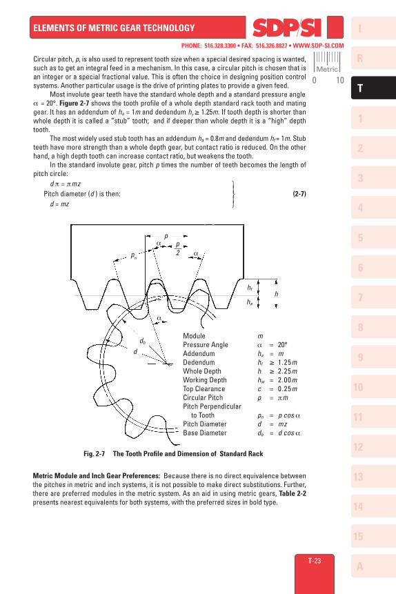
Circular pitch, p, is also used to represent tooth size when a special desired spacing is wanted, such as to get an integral feed in a mechanism. In this case, a circular pitch is chosen that is an integer or a special fractional value. This is often the choice in designing position control systems. Another particular usage is the drive of printing plates to provide a given feed. Most involute gear teeth have the standard whole depth and a standard pressure angle a = 20°. Figure 2-7 shows the tooth profile of a whole depth standard rack tooth and mating gear. It has an addendum of ha = 1m and dedendum hf ≥ 1.25m. If tooth depth is shorter than whole depth it is called a “stub” tooth; and if deeper than whole depth it is a “high” depth tooth. The most widely used stub tooth has an addendum ha = 0.8m and dedendum hf = 1m. Stub teeth have more strength than a whole depth gear, but contact ratio is reduced. On the other hand, a high depth tooth can increase contact ratio, but weakens the tooth. In the standard involute gear, pitch p times the number of teeth becomes the length of pitch circle: d p = pmz Pitch diameter (d ) is then: (2-7) d = mz
Fig. 2-7 The Tooth Profile and Dimension of Standard Rack
p
pn
aa
a
p––2
db
hf
d
ha
h
Module mPressure Angle a = 20°Addendum ha = mDedendum hf ≥ 1.25mWhole Depth h ≥ 2.25mWorking Depth hw = 2.00mTop Clearance c = 0.25mCircular Pitch p = pmPitch Perpendicular to Tooth pn = p cos aPitch Diameter d = mzBase Diameter db = d cos a
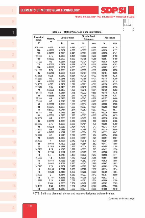
Metric Module and Inch Gear Preferences: Because there is no direct equivalence between the pitches in metric and inch systems, it is not possible to make direct substitutions. Further, there are preferred modules in the metric system. As an aid in using metric gears, Table 2-2 presents nearest equivalents for both systems, with the preferred sizes in bold type.
Metric
0 10
I
R
1
2
3
4
5
6
7
8
9
10
11
12
13
T
14
15
A
PHONE: 516.328.3300 • FAX: 516.326.8827 • WWW.SDP-SI.COM
ELEMENTS OF METRIC GEAR TECHNOLOGY
T-24
203.2000200180
169.333150
127.000125120
101.60096
92.363684.6667
8078.153872.5714
7267.733
6463.50050.800
504844
42.33340
36.285736
33.866732
31.750030
28.222228
25.40002422
20.32002018
16.93331615
14.51431413
12.700012
11.288911
10.160010
0.01550.01570.01750.01860.02090.02470.02510.02620.03090.03270.03400.03710.03930.04020.04330.04360.04640.04910.04950.06180.06280.06550.07140.07420.07850.08660.08730.09280.09820.09890.10470.11130.11220.12370.13090.14280.15460.15710.17450.18550.19630.20940.21640.22440.24170.24740.26180.27830.28560.30920.3142
0.1250.127000.14111
0.150.16933
0.20.203200.21167
0.250.264580.2750.3
0.317500.3250.35
0.352780.375
0.396880.40.5
0.508000.529170.57727
0.60.63500
0.70.70556
0.750.79375
0.80.84667
0.90.90714
11.05831.15451.25
1.27001.4111
1.51.58751.69331.75
1.81431.9538
22.11672.25
2.30912.50
2.5400
0.3930.3990.4430.4710.5320.6280.6380.6650.7850.8310.8640.9420.9971.0211.1001.1081.1781.2471.2571.5711.5961.6621.8141.8851.9952.1992.2172.3562.4942.5132.6602.8272.8503.1423.3253.6273.9273.9904.4334.7124.9875.3205.4985.7006.1386.2836.6507.0697.2547.8547.980
0.00770.00790.00870.00930.01050.01240.01260.01310.01550.01640.01700.01860.01960.02010.02160.02180.02320.02450.02470.03090.03140.03270.03570.03710.03930.04330.04360.04640.04910.04950.05240.05570.05610.06180.06540.07140.07730.07850.08730.09280.09820.10470.10820.11220.12080.12370.13090.13910.14280.15460.1571
0.1960.1990.2220.2360.2660.3140.3190.3320.3930.4160.4320.4710.4990.5110.5500.5540.5890.6230.6280.7850.7980.8310.9070.9420.9971.1001.1081.1781.2471.2571.3301.4141.4251.5711.6621.8131.9631.9952.2172.3562.4942.6602.7492.8503.0693.1423.3253.5343.6273.9273.990
0.00490.00500.00560.00590.00670.00790.00800.00830.00980.01040.01080.01180.01250.01280.01380.01390.01480.01560.01570.01970.02000.02080.02270.02360.02500.02760.02780.02950.03130.03150.03330.03540.03570.03940.04170.04550.04920.05000.05560.05910.06250.06670.06890.07140.07690.07870.08330.08860.09090.09840.1000
0.1250.1270.1410.1500.1690.2000.2030.2120.2500.2650.2750.3000.3180.3250.3500.3530.3750.3970.4000.5000.5080.5290.5770.6000.6350.7000.7060.7500.7940.8000.8470.9000.9071.0001.0581.1551.2501.2701.4111.5001.5881.6931.7501.8141.9542.0002.1172.2502.3092.5002.540
DiametralPitch,
P
Module,m
Circular PitchCircular Tooth
Thickness Addendum
in mm in mm in mm
Table 2-2 Metric/American Gear Equivalents
NOTE: Bold face diametral pitches and modules designate preferred values.
Continued on the next page
Metric
0 10
I
R
1
2
3
4
5
6
7
8
9
10
11
12
13
T
14
15
A
PHONE: 516.328.3300 • FAX: 516.326.8827 • WWW.SDP-SI.COM
ELEMENTS OF METRIC GEAR TECHNOLOGY
T-25
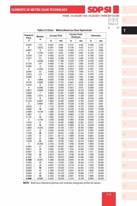
Table 2-2 (Cont.) Metric/American Gear Equivalents
NOTE: Bold face diametral pitches and modules designate preferred values.
9.23649
8.46678
7.81547.2571
76.77336.3500
65.64445.34745.0800
54.61824.2333
43.90773.62863.50003.17503.1416
32.82222.54002.50002.30912.1167
21.81431.58751.50001.41111.27001.15451.05831.0160
10.94070.90710.84670.79380.76970.75000.70560.65130.63500.60480.56440.50800.5000
0.34010.34910.37110.39270.40200.43290.44880.46380.49470.52360.55660.58750.61840.62830.68030.74210.78540.80400.86580.89760.98951.00001.04721.11321.23681.25661.36051.48421.57081.73161.97902.09442.22632.47372.72112.96843.09213.14163.33953.46323.71053.95794.08164.18884.45274.82374.94745.19485.56586.18426.2832
2.752.8222
33.17503.253.5
3.62863.75
44.2333
4.54.75
55.08005.5000
66.35006.5000
77.2571
88.08518.4667
910
10.1601112
12.7001416
16.9331820222425
25.4002728303233
33.867363940424550
50.800
8.6398.8669.4259.975
10.21010.99611.40011.78112.56613.29914.13714.92315.70815.95917.27918.85019.94920.42021.99122.79925.13325.40026.59928.27431.41631.91934.55837.69939.89843.98250.26553.19856.54962.83269.11575.39878.54079.79684.82387.96594.248100.531103.673106.395113.097122.522125.664131.947141.372157.080159.593
0.17010.17450.18550.19630.20100.21640.22440.23190.24740.26180.27830.29380.30920.31420.34010.37110.39270.40200.43290.44880.49470.50000.52360.55660.61840.62830.68030.74210.78540.86580.98951.04721.11321.23681.36051.48421.54611.57081.66971.73161.85531.97902.04082.09442.22632.41192.47372.59742.78293.09213.1416
4.3204.4334.7124.9875.1055.4985.7005.8906.2836.6507.0697.4617.8547.9808.6399.4259.975
10.21010.99611.39912.56612.70013.29914.13715.70815.95917.27918.85019.94921.99125.13326.59928.27431.41634.55837.69939.27039.89842.41243.98247.12450.26551.83653.19856.54961.26162.83265.97370.68678.54079.796
0.10830.11110.11810.12500.12800.13780.14290.14760.15750.16670.17720.18700.19690.20000.21650.23620.25000.25590.27560.28570.31500.31830.33330.35430.39370.40000.43310.47240.50000.55120.62990.66670.70870.78740.86610.94490.98431.00001.06301.10241.18111.25981.29921.33331.41731.53541.57481.65351.77171.96852.0000
2.7502.8223.0003.1753.2503.5003.6293.7504.0004.2334.5004.7505.0005.0805.5006.0006.3506.5007.0007.2578.0008.0858.4679.00010.00010.16011.00012.00012.70014.00016.00016.93318.00020.00022.00024.00025.00025.40027.00028.00030.00032.00033.00033.86736.00039.00040.00042.00045.00050.00050.800
DiametralPitch,
P
Module,m
Circular PitchCircular Tooth
ThicknessAddendum
in mm in mm in mm
Metric
0 10
I
R
1
2
3
4
5
6
7
8
9
10
11
12
13
T
14
15
A
PHONE: 516.328.3300 • FAX: 516.326.8827 • WWW.SDP-SI.COM
ELEMENTS OF METRIC GEAR TECHNOLOGY
T-26
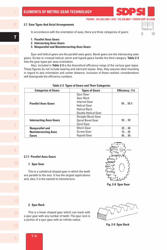
2.7 Gear Types And Axial Arrangements
In accordance with the orientation of axes, there are three categories of gears:
1. Parallel Axes Gears 2. Intersecting Axes Gears 3. Nonparallel and Nonintersecting Axes Gears
Spur and helical gears are the parallel axes gears. Bevel gears are the intersecting axes gears. Screw or crossed helical, worm and hypoid gears handle the third category. Table 2-3 lists the gear types per axes orientation. Also, included in Table 2-3 is the theoretical efficiency range of the various gear types. These figures do not include bearing and lubricant losses. Also, they assume ideal mounting in regard to axis orientation and center distance. Inclusion of these realistic considerations will downgrade the efficiency numbers.
Table 2-3 Types of Gears and Their Categories
98 ... 99.5
98 ... 99
30 ... 9070 ... 9596 ... 98
Parallel Axes Gears
Intersecting Axes Gears
Nonparallel and Nonintersecting Axes Gears
Spur GearSpur RackInternal GearHelical GearHelical RackDouble Helical GearStraight Bevel GearSpiral Bevel GearZerol GearWorm GearScrew GearHypoid Gear
Categories of Gears Types of Gears Efficiency (%)
2.7.1 Parallel Axes Gears
1. Spur Gear This is a cylindrical shaped gear in which the teeth are parallel to the axis. It has the largest applications and, also, it is the easiest to manufacture.
2. Spur Rack This is a linear shaped gear which can mesh with a spur gear with any number of teeth. The spur rack is a portion of a spur gear with an infinite radius.
Fig. 2-8 Spur Gear
Fig. 2-9 Spur Rack
Metric
0 10
I
R
1
2
3
4
5
6
7
8
9
10
11
12
13
T
14
15
A
PHONE: 516.328.3300 • FAX: 516.326.8827 • WWW.SDP-SI.COM
ELEMENTS OF METRIC GEAR TECHNOLOGY
T-27
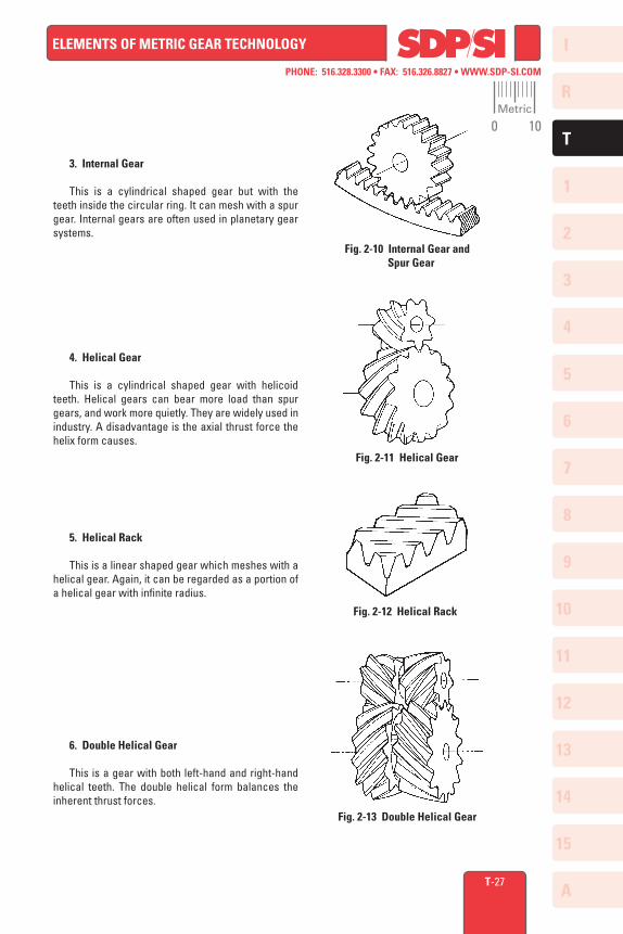
3. Internal Gear
This is a cylindrical shaped gear but with the teeth inside the circular ring. It can mesh with a spur gear. Internal gears are often used in planetary gear systems.
4. Helical Gear
This is a cylindrical shaped gear with helicoid teeth. Helical gears can bear more load than spur gears, and work more quietly. They are widely used in industry. A disadvantage is the axial thrust force the helix form causes.
5. Helical Rack
This is a linear shaped gear which meshes with a helical gear. Again, it can be regarded as a portion of a helical gear with infinite radius.
6. Double Helical Gear
This is a gear with both left-hand and right-hand helical teeth. The double helical form balances the inherent thrust forces.
Fig. 2-10 Internal Gear and Spur Gear
Fig. 2-11 Helical Gear
Fig. 2-12 Helical Rack
Fig. 2-13 Double Helical Gear
Metric
0 10
I
R
1
2
3
4
5
6
7
8
9
10
11
12
13
T
14
15
A
PHONE: 516.328.3300 • FAX: 516.326.8827 • WWW.SDP-SI.COM
ELEMENTS OF METRIC GEAR TECHNOLOGY
T-28
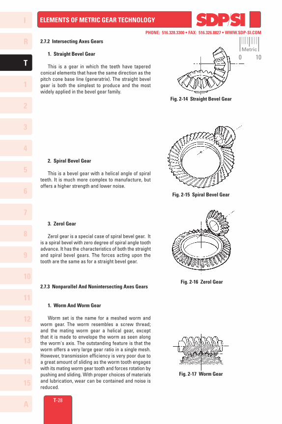
2.7.2 Intersecting Axes Gears
1. Straight Bevel Gear
This is a gear in which the teeth have tapered conical elements that have the same direction as the pitch cone base line (generatrix). The straight bevel gear is both the simplest to produce and the most widely applied in the bevel gear family.
2. Spiral Bevel Gear
This is a bevel gear with a helical angle of spiral teeth. It is much more complex to manufacture, but offers a higher strength and lower noise.
3. Zerol Gear
Zerol gear is a special case of spiral bevel gear. It is a spiral bevel with zero degree of spiral angle tooth advance. It has the characteristics of both the straight and spiral bevel gears. The forces acting upon the tooth are the same as for a straight bevel gear.
2.7.3 Nonparallel And Nonintersecting Axes Gears
1. Worm And Worm Gear
Worm set is the name for a meshed worm and worm gear. The worm resembles a screw thread; and the mating worm gear a helical gear, except that it is made to envelope the worm as seen along the worm's axis. The outstanding feature is that the worm offers a very large gear ratio in a single mesh. However, transmission efficiency is very poor due to a great amount of sliding as the worm tooth engages with its mating worm gear tooth and forces rotation by pushing and sliding. With proper choices of materials and lubrication, wear can be contained and noise is reduced.
Fig. 2-14 Straight Bevel Gear
Fig. 2-15 Spiral Bevel Gear
Fig. 2-16 Zerol Gear
Fig. 2-17 Worm Gear
Metric
0 10
I
R
1
2
3
4
5
6
7
8
9
10
11
12
13
T
14
15
A
PHONE: 516.328.3300 • FAX: 516.326.8827 • WWW.SDP-SI.COM
ELEMENTS OF METRIC GEAR TECHNOLOGY
T-29
2. Screw Gear (Crossed Helical Gear)
Two helical gears of opposite helix angle will mesh if their axes are crossed. As separate gear components, they are merely conventional helical gears. Installation on crossed axes converts them to screw gears. They offer a simple means of gearing skew axes at any angle. Because they have point contact, their load carrying capacity is very limited.
2.7.4 Other Special Gears
1. Face Gear
This is a pseudobevel gear that is limited to 90O intersecting axes. The face gear is a circular disc with a ring of teeth cut in its side face; hence the name face gear. Tooth elements are tapered towards its center. The mate is an ordinary spur gear. It offers no advantages over the standard bevel gear, except that it can be fabricated on an ordinary shaper gear generating machine.
2. Double Enveloping Worm Gear
This worm set uses a special worm shape in that it partially envelops the worm gear as viewed in the direction of the worm gear axis. Its big advantage over the standard worm is much higher load capacity. However, the worm gear is very complicated to design and produce, and sources for manufacture are few.
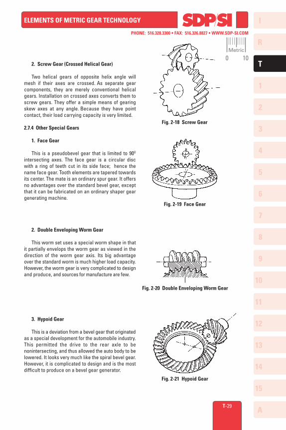
3. Hypoid Gear
This is a deviation from a bevel gear that originated as a special development for the automobile industry. This permitted the drive to the rear axle to be nonintersecting, and thus allowed the auto body to be lowered. It looks very much like the spiral bevel gear. However, it is complicated to design and is the most difficult to produce on a bevel gear generator.
Fig. 2-18 Screw Gear
Fig. 2-19 Face Gear
Fig. 2-20 Double Enveloping Worm Gear
Fig. 2-21 Hypoid Gear
Metric
0 10